1
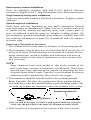
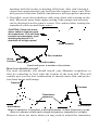
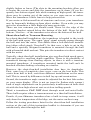
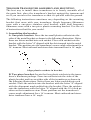
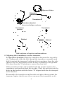
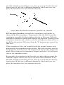
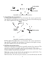
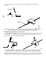
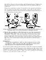
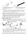
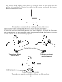
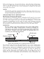
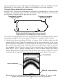
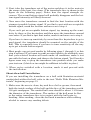
Pub. 988-0147-582 Installation Instructions for Skimmer Transducers Single- or Dual-Frequency This instruction booklet will help you install your Skimmer transducer on a transom, on a trolling motor or inside a hull. These instructions cover both single- and dual-frequency Skimmer transducers. Read these instructions carefully before attempting the installation. Determine which of the mounting positions is right for your boat. Use extreme care if mounting the transducer inside the hull, because once it is epoxied into position, the transducer usually cannot be removed. Remember, the transducer location and installation is the most critical part of a sonar installation! The smaller single-frequency Skimmers typically use a one-piece, stainless steel mounting bracket. The larger dual-frequency Skimmers typically use a two-piece, plastic mounting bracket. The trolling motor mount uses a one-piece plastic bracket with an adjustable strap. These are all "kick-up" mounting brackets. They help prevent damage if the transducer strikes an object while the boat is moving. If the transducer does "kick-up," the bracket can easily be pushed back into place without tools. Depending on your sonar unit's connectors, your transducer cable may also have the sonar unit's power cable attached to it. If that is the case, be sure to install the transducer first, before connecting the power cable to a power source. See the instructions in your sonar unit's manual for connecting the power cable to a battery or other power supply. (Lost your manual? Most current product manuals are available for free download from the manufacturers' web sites. See the back page for web links.) Recommended Tools and supplies If you prefer the option of routing the cable through the transom, you will need either a 1" drill bit or a 5/8" drill bit depending on the type of cable connector (see figure at top of page 11). Each transom mount requires use of a high quality, marine grade above- or below-waterline sealant/adhesive compound. The following installation types also call for these recommended tools and required supplies (supplies are not included): Single-frequency transom installations Tools include: two adjustable wrenches, drill, #29 (0.136") drill bit, flathead screwdriver. Supplies: none. 1 Dual-frequency transom installations Tools: two adjustable wrenches, drill, #20 (0.161") drill bit, flat-head screwdriver. Supplies: four, 1" long, #12 stainless steel slotted wood screws. Single-frequency trolling motor installations Tools: two adjustable wrenches, flat-head screwdriver. Supplies: plastic cable ties. Shoot-through hull installations Tools: these will vary depending on your hull's composition. Consult your boat dealer or manufacturer. Other tools are a wooden craft stick or similar tool for stirring and applying epoxy, and a paper plate or piece of cardboard to mix the epoxy on. Supplies: rubbing alcohol, 100 grit sandpaper, specially formulated epoxy adhesive available from LEI (see ordering information on page 20). A sandwich hull also requires polyester resin. Selecting a Transducer Location 1. The location must be in the water at all times, at all operating speeds. 2. The transducer must be placed in a location that has a smooth flow of water at all times. If the transducer is not placed in a smooth flow of water, interference caused by bubbles and turbulence will show on the sonar's display in the form of random lines or dots whenever the boat is moving. NOTE: Some aluminum boats with strakes or ribs on the outside of the hull create large amounts of turbulence at high speed. These boats typically have large outboard motors capable of propelling the boat at speeds faster than 35 mph. Typically, a good transom location on aluminum boats is between the ribs closest to the engine. 3. The transducer should be installed with its face pointing straight down, if possible. For shoot-thru applications: Many popular fishing boat hulls have a flat keel pad that offers a good mounting surface. On vee hulls, try to place the transducer where the deadrise is 10° or less. Deadrise less than 10° Strakes Pad Left, vee pad hull; right, vee hull. A pod style transducer is shown here, but the principle is the same for Skimmers inside a hull. 4. If the transducer is mounted on the transom, make sure it doesn't 2 interfere with the trailer or hauling of the boat. Also, don't mount it closer than approximately one foot from the engine's lower unit. This will prevent cavitation (bubble) interference with propeller operation. 5. If possible, route the transducer cable away from other wiring on the boat. Electrical noise from engine wiring, bilge pumps and aerators can be displayed on the sonar's screen. Use caution when routing the transducer cable around these wires. CAUTION: Clamp the transducer cable to transom near the transducer. This will help prevent the transducer from entering the boat if it is knocked off at high speed. Good location Poor location Good location Good location Poor angle Good and poor transducer locations. How low should you go? For most situations, you should install your Skimmer transducer so that its centerline is level with the bottom of the boat hull. This will usually give you the best combination of smooth water flow and protection from bangs and bumps. Transom Transom Transducer centerline Hull bottom Hull bottom Align transducer centerline with hull bottom. A dual frequency transducer is shown at left and a single frequency transducer at right. However, there are times when you may need to adjust the transducer 3 slightly higher or lower. (The slots in the mounting brackets allow you to loosen the screws and slide the transducer up or down.) If you frequently lose bottom signal lock while running at high speed, the transducer may be coming out of the water as you cross waves or wakes. Move the transducer a little lower to help prevent this. If you cruise or fish around lots of structure and cover, your transducer may be frequently kicking up from object strikes. If you wish, you may move the transducer a little higher for more protection. There are two extremes you should avoid. Never let the edge of the mounting bracket extend below the bottom of the hull. Never let the bottom – the face – of the transducer rise above the bottom of the hull. Shoot-thru-hull vs. Transom Mounting In a shoot-thru-hull installation, the transducer is bonded to the inside of the hull with epoxy. The sonar "ping" signal actually passes through the hull and into the water. This differs from a bolt-thru-hull installation (often called simply "thru-hull"). In that case, a hole is cut in the hull and a specially designed transducer is mounted through the hull with a threaded shaft and nut. This puts the transducer in direct contact with the water. Typically, shoot-thru-hull installations give excellent high speed operation and good to excellent depth capability. There is no possibility of transducer damage from floating objects, as there is with a transommounted transducer. A transducer mounted inside the hull can't be knocked off when docking or loading on a trailer. However, the shoot-thru-hull installation does have its drawbacks. First, some loss of sensitivity does occur, even on the best hulls. This varies from hull to hull, even from different installations on the same hull. This is caused by differences in hull lay-up and construction. Second, the transducer angle cannot be adjusted for the best fish arches on your sonar display. (This is not an issue for flasher-style sonars.) Lack of angle adjustment can be particularly troublesome on hulls that sit with the bow high when at rest or at slow trolling speeds. Third, a transducer CAN NOT shoot through wood and metal hulls. Those hulls require either a transom mount or a thru-hull installation. Fourth, if your Skimmer transducer has a built in temp sensor, it will only show the temperature of the bilge, not the water surface temp. Follow the testing procedures listed in the shoot-thru-hull installation section at the end of this instruction booklet to determine if you can satisfactorily shoot through the hull. 4 TRANSOM TRANSDUCER ASSEMBLY AND MOUNTING The best way to install these transducers is to loosely assemble all of the parts first, place the transducer's bracket against the transom and see if you can move the transducer so that it's parallel with the ground. The following instructions sometimes vary depending on the mounting bracket that came with your transducer. Single frequency Skimmers come with a one-piece stainless steel bracket, while dual frequency Skimmers come with a two-piece plastic mounting bracket. Use the set of instructions that fits your model. 1. Assembling the bracket. A. One-piece bracket: Press the two small plastic ratchets into the sides of the metal bracket as shown in the following illustration. Notice there are letters molded into each ratchet. Place each ratchet into the bracket with the letter "A" aligned with the dot stamped into the metal bracket. This position sets the transducer's coarse angle adjustment for a 14° transom. Most outboard and stern-drive transoms have a 14° angle. Dot Align plastic ratchets in bracket. B. Two-piece bracket: Locate the four plastic ratchets in the transducer's hardware package. Press two ratchets into the sides of the plastic bracket and two on either side of the transducer as shown in the following illustrations. Notice there are letters molded into each ratchet. Place the ratchets into the bracket with the letter "A" aligned with the alignment mark molded into the bracket. Place the ratchets onto the transducer with the letter "A" aligned with the 12 o'clock position on the transducer stem. These positions set the transducer's coarse angle adjustment for a 14° transom. Most outboard and sterndrive transoms have a 14° angle. 5 Alignment letters Alignment positions Transducer Transducer bracket Insert and align ratchets. Transducer bracket Transducer Ratchet Ratchet Add ratchets to bracket and transducer. 2. Aligning the transducer on the transom. A. One-piece bracket: Slide the transducer between the two ratchets. Temporarily slide the bolt though the transducer assembly and hold it against the transom. Looking at the transducer from the side, check to see if it will adjust so that its face is parallel to the ground. If it does, then the "A" position is correct for your hull. If the transducer's face isn't parallel with the ground, remove the transducer and ratchets from the bracket. Place the ratchets into the holes in the bracket with the letter "B" aligned with the dot stamped in the bracket. Reassemble the transducer and bracket and place them against the transom. Again, check to see if you can move the transducer so it's 6 parallel with the ground. If you can, then go to step 3A. If it doesn't, repeat step 2A, but use a different alignment letter until you can place the transducer on the transom correctly. Ratchets Insert bolt and check transducer position on transom. B. Two-piece bracket: Assemble the transducer and bracket as shown in the following figure. Temporarily slide the bolt though the transducer assembly but don't tighten the nut at this time. Hold the assembled transducer and bracket against the transom. Looking at the transducer from the side, check to see if it will adjust so that its face is parallel to the ground. If it does, then the "A" positions are correct for your hull. If the transducer's face isn't parallel with the ground, remove and disassemble the transducer and ratchets. Place the ratchets into the bracket holes with the letter "B" aligned with the bracket alignment mark. Place them on the transducer aligned with the 12 o'clock position on the transducer stem. Reassemble the transducer and bracket and place them against the transom. Again, check to see if you can move the transducer so it's parallel with the ground. If you can, then go to step 3B. If it doesn't, repeat step 2B, but use a different alignment letter until you can place the transducer on the transom correctly. 7 Lock washer Bolt Nut Flat washer Flat washer Assemble transducer and bracket. 3. Assembling the transducer. A. One-piece bracket: Once you determine the correct position for the ratchets, assemble the transducer as shown in the following figure. Don't tighten the lock nut at this time. Nut Metal washer Rubber washers Metal washer Bolt Assemble transducer and bracket. B. Two-piece bracket: Once you determine the correct position for the ratchets, assemble the transducer as shown in the figure in step 2B. Don't tighten the lock nut at this time. 4. Drilling mounting holes. Hold the transducer and bracket assembly against the transom. The transducer should be roughly parallel to the ground. The transducer's centerline should be in line with the bottom of the hull. Don't let the bracket extend below the hull! Mark the center of each slot for the mounting screw pilot holes. You will drill one hole in the center of each slot. Drill the holes. For the one-piece bracket, use the #29 bit (for the #10 8 screws). For the two-piece bracket, use the #20 bit (for the #12 screws). Transom Transom Position transducer mount on transom and mark mounting holes. Side view shown at left and seen from above at right. 5. Attaching transducer to transom. A. One-piece bracket: Remove the transducer from the bracket and re-assemble it with the cable passing through the bracket over the bolt as shown in the following figures. For single frequency Skimmer, route cable over bolt and through bracket. Side view shown at left and seen from above at right. Both bracket types: Attach the transducer to the transom. Slide the transducer up or down until it's aligned properly with the bottom of 9 the hull as shown in the preceding and following figures. Tighten the bracket's mounting screws, sealing them with the sealant/adhesive compound. Adjust the transducer so that it's parallel to the ground and tighten the nut until it touches the outer washer, then add 1/4 turn. Don't over tighten the lock nut! If you do, the transducer won't "kick-up" if it strikes an object in the water. Bottom of hull Flat-bottom hull Deep-"vee" hull Align transducer centerline with hull bottom and attach transducer to transom. Rear view of dual frequency Skimmer shown. 6. Route the transducer cable through or over the transom to the sonar unit. Make sure to leave some slack in the cable at the transducer. If possible, route the transducer cable away from other wiring on the boat. Electrical noise from the engine's wiring, bilge pumps, VHF radio wires and cables, and aerators can be picked up by the sonar. Use caution when routing the transducer cable around these wires. WARNING: Clamp the transducer cable to the transom close to the transducer. This can prevent the transducer from entering the boat if it is knocked off at high speed. If you need to drill a hole in the transom to pass the connector through, the required hole size will depend on the connector on the end of your transducer's cable. If the transducer has a manual locking collar connector, you will need to drill a 1" hole. If it has a push-on self-sealing connector, you will need to drill a 5/8" hole. 10 Manual locking collar connector requires a 1" hole. Push-on self-sealing connector requires a 5/8" hole. Caution: If you drill a hole in the transom for the cable, make sure it is located above the waterline. After installation, be sure to seal the hole with the same marine grade above- or below-waterline sealant/adhesive used for the mounting screws. 7. Make a test run to determine the results. If the bottom is lost at high speed, or if noise appears on the display, try sliding the transducer bracket down. This puts the transducer deeper into the water, hopefully below the turbulence causing the noise. Don't allow the transducer bracket to go below the bottom of the hull! TROLLING MOTOR BRACKET INSTALLATION (single-frequency only) 1. Attach the TMB-S bracket to the transducer as shown in the following figure, using the hardware supplied with the transducer. (Note: The internal tooth washer is supplied with the TMB-S.) Internal tooth washer Bolt TMB-S bracket Nut Flat washer Attach motor mounting bracket to transducer. 2. Slide the adjustable strap supplied with the TMB-S through the slot in the transducer bracket and wrap it around the trolling motor. Position the transducer to aim straight down when the motor is in the water. Tighten the strap securely. 3. Route the transducer cable alongside the trolling motor shaft. Use plastic ties (not included) to attach the transducer cable to the troll11 ing motor shaft. Make sure there is enough slack in the cable for the motor to turn freely. Route the cable to the sonar unit and the transducer is ready for use. Transducer mounted on trolling motor, side view. TRANSDUCER ORIENTATION AND FISH ARCHES If you do not get good fish arches on your display, it could be because the transducer is not parallel with the ground when the boat is at rest in the water or at slow trolling speeds. Partial fish arches Transducer aimed too far back Transducer aimed too far forward Full fish arch Proper transducer angle Transducer angles and their effects on fish arches. 12 If the arch slopes up – but not back down – then the front of the transducer is too high and needs to be lowered. If only the back half of the arch is printed, then the nose of the transducer is angled too far down and needs to be raised. NOTE: Periodically wash the transducer's face with soap and water to remove any oil film. Oil and dirt on the face will reduce the sensitivity or may even prevent operation. SHOOT-THRU-HULL PREPARATION Hulls With Floatation Materials The transducer installation inside a fiberglass hull must be in an area that does not have air bubbles in the resin or separated fiberglass layers. The sonar signal must pass through solid fiberglass. A successful transducer installation can be made on hulls with flotation materials (such as plywood, balsa wood or foam) between layers of fiberglass if the material is removed from the chosen area. See the figure below. WARNING: Do not remove any material from your inner hull unless you know the hull's composition. Careless grinding or cutting on your hull can result in damage that could sink your boat. Contact your boat dealer or manufacturer to confirm your hull specifications. Fill with resin Fill with resin Inner hull Flotation material Epoxy to hull first Outer hull Epoxy the transducer to a solid portion of the hull. For example, some (but not all) manufacturers use a layer of fiberglass, then a core of balsa wood, finishing with an outer layer of fiberglass. Removing the inner layer of fiberglass and the balsa wood core exposes the outer layer of fiberglass. The transducer can then be epoxied directly to the outer layer of fiberglass. After the epoxy cures for 24 hours, fill the remaining space with polyester resin. When the job is finished, the hull is watertight and structurally sound. Remember, the 13 sonar signal must pass through solid fiberglass. Any air bubbles in the fiberglass or the epoxy will reduce or eliminate the sonar signals. Testing Determines Best Location Ideally, the shoot-thru transducer should be installed as close to the transom as possible, close to the centerline. This will give you the best performance during high speed maneuvers. Transducer location (high speed) Transducer location (trolling speed) Shoot-thru-hull transducer locations for high speed or trolling speed operation. To choose the proper location for shoot-thru-hull mounting, follow these testing procedures: (You may need a helper to complete these steps.) 1. Anchor the boat in about 30 feet of water. Add a little water to the sump of the boat. Plug the transducer into the sonar unit, turn it on, then hold the transducer over the side of the boat in the water. Adjust the sensitivity and range controls until a second bottom echo is seen on the display. (You'll need to turn off Auto Sensitivity, Auto Depth Range and ASP. Try a range setting that is two to three times the water depth. The harder (more rocky) the bottom, the easier it will be to get a second bottom signal.) Don't touch the controls once they've been set. True bottom Second bottom Manual range setting Example of a second bottom signal. Unit is in 30 feet of water, with range set at 80 feet and sensitivity set at 87 percent. 14 2. Next, take the transducer out of the water and place it in the water in the sump of the boat, face down. (The transducer face is shown in the figure on the following page.) Notice how the signal strength decreases. The second bottom signal will probably disappear and the bottom signal intensity will likely decrease. 3. Now move the transducer around to find the best location with the strongest possible bottom signal. If you find a spot with an acceptable bottom signal, mark the location and move on to step 4. If you can't get an acceptable bottom signal, try turning up the sensitivity by three or five keystrokes and then move the transducer around once more. If you find a spot that works, mark it and move on to step 4. If you have to turn up sensitivity by more than five keystrokes to get a good signal, the transducer should be mounted on the outside of the hull. This is especially true if you have to turn sensitivity all the way up to get a decent bottom signal. 4. Most people can get good results by following steps 1 through 3, so this step is optional. If you want to make an extra effort to be absolutely sure that your selected location will work under all conditions, make a test run with the boat on plane and observe the bottom signal. You'll need to figure some way to prop the transducer into position while you make your test run. (A brick or two might be sufficient to hold it in place.) 5. When you're satisfied with a location, mark it and proceed with the installation. Shoot-thru-hull Installation If you are installing the transducer on a hull with floatation material sandwiched within the hull, refer to the text "Hulls With Flotation Materials" beginning on page 13. 1. Make sure the area is clean, dry and free of oil or grease, then sand both the inside surface of the hull and the face of the transducer with 100 grit sandpaper. The sanded hull area should be about 1-1/2 times the diameter of the transducer. The surface of the hull must be flat so the entire transducer face is in contact with the hull prior to bonding. After sanding, clean the hull and transducer with rubbing alcohol to remove any sanding debris. 15 Spread epoxy here Sand this surface (unit's face) Orient the Skimmer with the nose facing the bow of the boat. To bow Epoxy transducer to hull. WARNING: Use only the epoxy available from LEI. It has been formulated to work with these installation procedures. Other epoxy types may be too thin or may not cure to the right consistency for optimum transducer performance. 2. The epoxy consists of the epoxy itself and a hardener. Remove the two compounds from the package and place them on the paper plate. Thoroughly stir the two compounds together until the mixture has a uniform color and consistency. Do not mix too fast or bubbles will form in the epoxy. After mixing, you have 20 minutes to complete the installation before the epoxy becomes unworkable. Spread a thin layer of epoxy (about 1/16" or 1.5 mm thick) on the face of the transducer as shown in the previous figure. Make sure there are no air pockets in the epoxy layer! Then, apply the remaining epoxy to the sanded area on the hull. 3. Press the transducer into the epoxy, twisting and turning it to force any air bubbles out from under the transducer face. Stop pressing when you bottom out on the hull. When you're finished, the face of the transducer should be parallel with the hull, with a minimum amount of epoxy between the hull and transducer. 4. Apply a weight, such as a brick, to hold the transducer in place while the epoxy cures. Be careful not to bump the transducer while the ep16 oxy is wet. Leave the weight in place for a minimum of three hours. Allow the epoxy to cure for 24 hours before moving the boat. 5. After the epoxy has cured, route the cable to the sonar unit and it's ready to use. 17 Notes 18 LEI EXTRAS FULL ONE-YEAR WARRANTY "We," "our," or "us" refers to LEI EXTRAS, INC., the manufacturer of this product. "You" or "your" refers to the first person who purchases this product as a consumer item for personal, family, or household use. We warrant this product against defects or malfunctions in materials and workmanship, and against failure to conform to this product's written specifications, all for one (1) year from the date of original purchase by you. WE MAKE NO OTHER EXPRESS WARRANTY OR REPRESENTATION OF ANY KIND WHATSOEVER CONCERNING THIS PRODUCT. Your remedies under this warranty will be available so long as you can show in a reasonable manner that any defect or malfunction in materials or workmanship, or any non-conformity with the product's written specifications, occurred within one year from the date of your original purchase, which must be substantiated by a dated sales receipt or sales slip. Any such defect, malfunction, or non-conformity which occurs within one year from your original purchase date will either be repaired without charge or be replaced with a new product identical or reasonably equivalent to this product, at our option, within a reasonable time after our receipt of the product. If such defect, malfunction, or non-conformity remains after a reasonable number of attempts to repair by us, you may elect to obtain without charge a replacement of the product or a refund for the product. THIS REPAIR, OR REPLACEMENT OR REFUND (AS JUST DESCRIBED) IS THE EXCLUSIVE REMEDY AVAILABLE TO YOU AGAINST US FOR ANY DEFECT, MALFUNCTION, OR NON-CONFORMITY CONCERNING THE PRODUCT OR FOR ANY LOSS OR DAMAGE RESULTING FROM ANY OTHER CAUSE WHATSOEVER. WE WILL NOT UNDER ANY CIRCUMSTANCES BE LIABLE TO ANYONE FOR ANY SPECIAL, CONSEQUENTIAL, INCIDENTAL, OR OTHER INDIRECT DAMAGE OF ANY KIND. Some states do not allow the exclusion or limitation of incidental or consequential damages, so the above limitations or exclusions may not apply to you. This warranty does NOT apply in the following circumstances: (1) when the product has been serviced or repaired by anyone other than us; (2) when the product has been connected, installed, combined, altered, adjusted, or handled in a manner other than according to the instructions furnished with the product; (3) when any serial number has been effaced, altered, or removed; or (4) when any defect, problem, loss, or damage has resulted from any accident, misuse, negligence, or carelessness, or from any failure to provide reasonable and necessary maintenance in accordance with the instructions of the owner's manual for the product. We reserve the right to make changes or improvements in our products from time to time without incurring the obligation to install such improvements or changes on equipment or items previously manufactured. This warranty gives you specific legal rights and you may also have other rights which may vary from state to state. REMINDER: You must retain the sales slip or sales receipt proving the date of your original purchase in case warranty service is ever required. LEI EXTRAS PO BOX 129, CATOOSA, OK 74015 19 How to Obtain Service… …in the USA: Contact the Factory Customer Service Department. Call toll-free: For Lowrance: 800-324-1356. For Eagle: 800-324-1354 8 a.m. to 5 p.m. Central Standard Time, M-F Lowrance Electronics and Eagle Electronics may find it necessary to change or end their shipping policies, regulations and special offers at any time. They reserve the right to do so without notice. …in Canada: Contact the Factory Customer Service Department. Call toll-free: 800-661-3983 905-629-1614 (not toll-free) 8 a.m. to 5 p.m. Eastern Standard Time, M-F …outside Canada and the USA: Contact the dealer in the country where you purchased your unit. To locate a dealer near you, see the instructions in paragraph number 1 below. Accessory Ordering Information LEI Extras, Inc. is the accessory source for sonar and GPS products manufactured by Lowrance Electronics and Eagle Electronics. To order Lowrance or Eagle accessories, please contact: 1) Your local marine dealer or consumer electronics store. To locate a Lowrance dealer, visit the web site, www.lowrance.com, and look for the Dealer Locator. To locate an Eagle dealer, visit the web site, www.eaglesonar.com, and look for the Dealer Locator. Or, consult your telephone directory for listings. 2) U.S. customers: LEI Extras Inc., PO Box 129, Catoosa, OK 74015-0129 Call toll free in the U.S., 800-324-0045, 8 a.m. to 5 p.m. Central Standard Time, M-F, or visit our web site www.lei-extras.com. 3) Canadian customers: Lowrance/Eagle Canada, 919 Matheson Blvd. E. Mississauga, Ontario L4W2R7 or fax 905-629-3118. Call toll free in Canada, 800-661-3983, or dial 905 629-1614 (not toll free), 8 a.m. to 5 p.m. Eastern Standard Time, M-F. For Lowrance and Eagle Products Pub. 988-0147-582 © Copyright 2003 All Rights Reserved LEI Extras, Inc. Printed in USA 041703 20