1
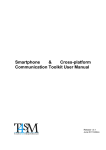
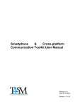
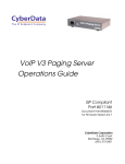
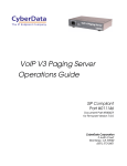
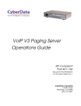
Configuring CyberData
Paging and Intercom
Systems for Use with
RingCentral
Document Part #930335A
CyberData Corporation
2555 Garden Road
Monterey, CA 93940
(831) 373-2601
www.CyberData.net
i
Contents
1.0 Introduction ............................................................................................................................................1
2.0 What are the products? .........................................................................................................................2
2.1 V2 Ceiling Speaker .........................................................................................................................2
2.2 Outdoor Intercom ..........................................................................................................................3
2.3 V2 Paging Amplifier ......................................................................................................................4
2.4 Paging Server ..................................................................................................................................5
3.0 System Architecture ...............................................................................................................................6
3.1 One-zone System Using your Existing Speakers ......................................................................6
3.2 A One-speaker System Using a New Speaker ...........................................................................7
3.3 A Multi-speaker System Using New IP Speakers .....................................................................8
3.4 A Multi-speaker System Using some New IP Speakers and some Analog Speakers ..........9
3.5 Adding an Intercom ..................................................................................................................... 10
4.0 Configuring your RingCentral Account ........................................................................................... 11
5.0 Configuring the Components .............................................................................................................14
5.1 V2 Ceiling Speaker ....................................................................................................................... 14
5.2 Paging Server ................................................................................................................................ 16
5.3 Intercom ......................................................................................................................................... 17
5.4 Paging Amplifier .......................................................................................................................... 19
Server Procedure
930335A
CyberData Corporation
1
1.0 Introduction
RingCentral does not presently offer native support for Intercom and paging systems. There are,
however, third-party VoIP/SIP based Intercom and paging systems that can work with the
RingCentral service as a third-party device. RingCentral cannot provide full support for these
devices, but we have documented the basic configuration of one such system sold by CyberData.
You can get more information on the CyberData system, including where to buy, here:
http://www.cyberdata.net/products/voip/digitalanalog/index.html. The website includes
product videos and other information to help you learn about the system’s capabilities.
The CyberData products are highly capable and configurable, and can meet almost any paging and
Intercom need in a variety of ways. The complete configuration scope for these products is well
beyond the scope of this document. In this document we discuss configuring for basic use cases, and
how to connect it to your RingCentral account. For more complex configuration, please review the
CyberData documentation or contact them and their authorized vendors for additional assistance.
The following products are covered in this document:
• Ceiling Speaker v2
•
Configuration would be nearly identical for the wall mount speaker with clock
•
There is a new ceiling speaker scheduled for release that includes two-way talkback – the
configuration will likely be very similar
• Outdoor Intercom
•
Configuration would be nearly identical for the indoor Intercom and emergency indoor
Intercom
• Paging amplifier v2
•
Configuration would be nearly identical for the Loudspeaker amplifier
• Paging server
Server Procedure
930335A
CyberData Corporation
2
What are the products?
2.0 What are the products?
2.1 V2 Ceiling Speaker
• V2 Ceiling Speaker– This ceiling-mount speaker can broadcast announcements in a large room.
Server Procedure
•
It can serve as its own extension, or you can aggregate several together using multicast with
the VoIP paging server. If you need more than 1 speaker, you will save on purchasing
additional VoIP lines by using the VoIP paging server to aggregate your speakers or
connecting standard analog speakers off of this speaker.
•
It is configured via a web interface.
•
Runs using PoE-enabled Ethernet. PoE is a standard for routing power over a network
cable. You’ll need a PoE-capable switch to power the device. See our article on
recommended switches.
•
Allows you to connect up to 1 additional analog speaker to it, to use to extend the range at
lower cost. Cyberdata offers such a speaker, or an appropriate third-party speaker could be
used. This additional speaker will only broadcast the same thing as the main speaker it is
connected to. See CyberData website for specifications of the wire gauge and speaker. There
is a wire connection on the back of the ceiling speaker for this hookup.
•
Allows you to connect a line-level output to an amplifier and run to any number of
additional speakers. These additional speakers will only broadcast the same thing as the
main speaker they are connected to. There is a wire connection on the back of the ceiling
speaker for this hookup.
930335A
CyberData Corporation
3
What are the products?
2.2 Outdoor Intercom
• Outdoor Intercom – the outdoor Intercom essentially serves the same role as a phone in the
system, except that it dials a fixed number. So a visitor can press the button, which will call the
extension of your choice (a receptionist for example). The person who answers the phone can
then speak with the visitor.
Server Procedure
•
It is configured via a web interface.
•
Runs using PoE-enabled Ethernet. PoE is a standard for routing power over a network
cable. You’ll need a PoE-capable switch to power the device. See our article on
recommended switches.
•
It is possible to integrate it with a door buzzer/opener system.
•
The Intercom can also be called from another extension and will automatically pickup and
initiate a two-way conversation.
•
Requires its own extension on the system (cannot be used with multicast).
930335A
CyberData Corporation
4
What are the products?
2.3 V2 Paging Amplifier
• V2 Paging Amplifier– serves as an interface from the SIP system to external speakers; external
speakers are connected with standard speaker wire, generally through a standard amplifier
Server Procedure
•
It can serve as its own extension, or you can aggregate several together using the VoIP
paging server.
•
It is configured via a web interface.
•
Runs using PoE-enabled Ethernet. PoE is a standard for routing power over a network
cable. You’ll need a PoE-capable switch to power the device. See our article on
recommended switches.
•
Allows you to connect a small number of standard speakers to it directly, or an unlimited
number by using a separate amplifier, to use to extend the range at lower cost. Cyberdata
offers such a speaker, or an appropriate third-party speaker could be used. All speakers
connected to the device will always announce the same thing. See CyberData website for
specifications of the wire gauge and speaker.
930335A
CyberData Corporation
5
What are the products?
2.4 Paging Server
• Paging Server – the paging server can aggregate several independent sets of VoIP enabled
speakers (ceiling speakers or paging amplifiers) into one extension on the system. In this way
you can use one RingCentral extension/line for paging, and this device can control which other
speakers are activated when you dial the paging extension. If you need more than 1 paging
zone, or want multiple speakers in one zone but you are not using analog speakers, you should
purchase this device to minimize your monthly line costs.
Server Procedure
•
It is configured via a web interface.
•
Runs using PoE-enabled Ethernet. PoE is a standard for routing power over a network
cable. You’ll need a PoE-capable switch to power the device. See our article on
recommended switches.
•
Can support multiple paging zones – when you dial the paging extension the paging server
can answer and you then press a keypad number for the pager zone you want to page.
930335A
CyberData Corporation
6
System Architecture
3.0 System Architecture
The system is extremely flexible and allows for a variety of configurations, using your existing
speakers, new speakers, or a combination. The system can be segregated into various zones or
treated as one zone. You can also use the Intercom devices for specialized needs such as entry doors.
Most speakers are one-way announce-only but the Intercom devices as well as special talkback or
two-way speakers allow a speakerphone type conversation. Following are several common
configuration scenarios. However, the options are many and you may wish to consult with a
CyberData installation professional for more complicated setups. In this case, the CyberData
installation professional could use this document to understand how to interface the CyberData
system with your RingCentral account.
3.1 One-zone System Using your Existing Speakers
Figure 1. One-zone System Using your Existing Speakers
Server Procedure
930335A
CyberData Corporation
7
System Architecture
3.2 A One-speaker System Using a New Speaker
Figure 2. A One-speaker System Using a New Speaker
One RC user required
Internet
Your phones and devices
Your local network
Ethernet
IP
Speaker
Server Procedure
930335A
CyberData Corporation
8
System Architecture
3.3 A Multi-speaker System Using New IP Speakers
Figure 3. A Multi-speaker System Using New IP Speakers
One RC user required
Internet
Your phones and devices
Ethernet
Your local network
IP
Speaker
Ethernet
Ethernet
Ethernet
Paging
Server
Server Procedure
930335A
IP
Speaker
IP
Speaker
CyberData Corporation
9
System Architecture
3.4 A Multi-speaker System Using some New IP Speakers and some Analog
Speakers
Figure 4. A Multi-speaker System Using some New IP Speakers and some Analog Speakers
Server Procedure
930335A
CyberData Corporation
10
System Architecture
3.5 Adding an Intercom
Figure 5. Adding an Intercom
Two RC users required
Internet
Your phones and devices
Ethernet
Your local network
IP
Speaker
Ethernet
Ethernet
Intercom
Server Procedure
Ethernet
Ethernet
Paging
Server
930335A
IP
Speaker
IP
Speaker
CyberData Corporation
11
Configuring your RingCentral Account
4.0 Configuring your RingCentral Account
You’ll need a RingCentral account with one available line for each paging device you need to
register. Generally this would be only 1 line needed. If you need only 1 paging speaker, you use a
single ceiling or wall speaker. If you need multiple paging speakers you can use a Paging Server or
amplifier, or the auxiliary connection from the ceiling speaker. In this way you can use multiple
speakers with one RingCentral line. If you are also using an Intercom you’ll need a separate line for
each Intercom.
4.1 Set up your RingCentral account:
4.1.1 If you don’t have a RingCentral account, set up your account here. Add an additional line
for the paging extension and select No Device as your phone.
4.1.2 If you already have an account, use your existing lines or add a new line from the
RingCentral service site using Add DigitalLines as shown in Figure 6. Select No Device
when prompted to choose a phone.
Figure 6. Adding DigitalLines:
Server Procedure
930335A
CyberData Corporation
12
Configuring your RingCentral Account
4.2 Record configuration information from RingCentral:
4.2.1 After purchasing your line(s), log in as an administrator and go to My Settings >
DigitalLines. You will see a list of the lines you purchased.
4.2.2 Locate each line you wish to use for your paging system. Make sure the E911 column
displays the word Edit. Otherwise, click Failed and provide the e911 data.
4.2.3 Click Setup Instructions for each line you wish to provision. Copy each of the five fields
shown in Figure 7 to use in configuring your speakers.
Figure 7. Copy these five fields:
4.3 Setup the paging extension(s) to remove usual answering rules.
4.3.1 By default, RingCentral extensions have various answering rules and voicemail enabled,
but these options are not logical for a paging extension so they can be disabled in your
RingCentral account.
4.3.2 Login as an administrator at service.ringcentral.com.
4.3.3 Go to the Company Settings tab, and click on Extensions.
Server Procedure
930335A
CyberData Corporation
13
Configuring your RingCentral Account
4.3.4 Click on Edit in the row of the extension you are using for paging to enter the
configuration for that extension.
4.3.4.1
Click Edit in the Business Hours row.
4.3.4.2
Switch ‘Play Introductory Greeting’ to No.
4.3.4.3
Switch ‘Enable Call Screening’ to No.
4.3.4.4
Switch ‘Play Connect Prompt’ to No.
4.3.4.5
Uncheck ‘Notify my Call Controller and wait’.
4.3.4.6 Make sure ‘Forward my calls’ is checked, and select from the list below the phone
number of the paging extension.
4.3.4.7
The maximum number of rings setting is not relevant as the speaker will answer
immediately.
4.3.4.8
Click Edit in the row of the phone number for the extension. In the dialog that
pops up set ‘Prompt me before connecting’ to off and click SUBMIT.
4.3.4.9
In section 3 for Take my messages select No.
4.3.4.10 Click SUBMIT.
4.3.5 The paging device on your network will have a phone number. If you wish to only allow
paging from internal extensions, or only from certain numbers, you can configure this in
the Allowed and Blocked functionality for the extension. As above, click on Edit in the
Extensions section of Company Settings.
4.3.5.1
Click on ‘Blocked/Allowed Numbers’ on the left-hand menu.
4.3.5.2
Click on ‘Block All Calls’.
4.3.5.3
Add numbers into the ‘Allowed’ section to allow calls to the paging device from
your internal numbers.
4.3.6 Remove the extension from the company directory.
4.3.6.1
If you’ve configured a company directory, which is accessible to external callers,
you’ll wish to remove the paging extension from the directory.
4.3.6.2
Click on Company Settings.
4.3.6.3
In the default extensions screen, between the Rules and My Settings columns,
there is a ‘Company Directory’ column. Click in the row for your paging
extension on the word ‘Yes’ to switch it to ‘No’.
4.3.6.4 If this column is not visible then you have not enabled company directory and can
skip this step.
Server Procedure
930335A
CyberData Corporation
14
Configuring the Components
5.0 Configuring the Components
5.1 V2 Ceiling Speaker
Install the ceiling speaker in the appropriate location following the instructions, and connect a PoEenabled Ethernet network cable to the device and plug it into your voice or main network. The
Status light should be green. Now use a paperclip or similar device to press and briefly hold the
RTFM button on the front of the speaker. The speaker will read aloud the IP address of the device. If
it does not do so then it is not properly plugged into a network with DHCP using a PoE-enabled
switch and cable.
5.1.1 On a computer connected to the same network, open a web browser and go to the address
that was read aloud by the speaker.
5.1.2 You should be prompted for a password. The default username and password are both
admin.
5.1.3 If you wish you can change the password on the initial screen.
5.1.4 There are tabs on the left for the various device configuration options:
• Device Config – controls various optional behavior aspects of the speaker. Most are
self-explanatory or see the user manual for further info. These settings can be left
defaulted for basic operations.
• Networking – control how the device connects to the network. For most users this can
be left as defaulted for DHCP. If desired the network settings can be changed.
• Sip Config – configures how the speaker should connect to a SIP account. If you are
using this speaker as a unit with the paging server, you must:
Server Procedure
5.1.4.1
Uncheck the ‘Enable SIP operation’ box and press Save at the bottom.
5.1.4.2
Press the Reboot button.
Note
If you are using this speaker as a standalone extension, connecting to your
RingCentral account without using the paging server, then you will input your
SIP account settings here.
5.1.4.3
In the ‘SIP Server’ field enter the value from your RC account labeled ‘SIP
Domain’ but leave off the ‘:5060’, so it should be ‘sip.ringcentral.com’.
5.1.4.4
In the ‘Remote SIP Port’ field enter 5060.
5.1.4.5
In the ‘Local SIP Port’ field enter 5060.
5.1.4.6
In the ‘Outbound Proxy’ field enter the value from your RC account labeled
‘Outbound Proxy’ but leave off the ‘:5090’ part, so just ‘sip.ringcentral.com’.
5.1.4.7
In the ‘Outbound Proxy Port’ field enter 5090.
5.1.4.8
In the ‘SIP User ID’ field enter the value from your RC account labeled ‘User
Name’.
5.1.4.9
In the ‘Authenticate ID’ field enter the value from your RC account labeled
930335A
CyberData Corporation
15
Configuring the Components
‘Authorization ID’.
5.1.4.10 In the ‘Authenticate Password’ field enter the value from your RC account
labeled ‘Password’.
5.1.4.11 Be sure that the ‘Register with a SIP Server’ box is checked.
5.1.4.12 Leave all other settings at default values.
5.1.4.13 Select Save.
5.1.4.14 Select Reboot.
5.1.4.15 After reboot your speaker should be configured. You can now dial it using the
extension or direct-dial number. The speaker should answer and you can
announce over the speaker.
• Multicast Config – configures how the speaker should respond to multi-cast packets.
This option is for using the speaker as a member of a group using the Paging Server. If
you are not using the paging server, leave this section at defaults. If you are using the
paging server, configure it as follows:
5.1.4.16 Check the box next to ‘Enable Multicast operation’.
5.1.4.17 The system has the capability to have multiple addresses it is listening on and at
different priorities. For the purposes of this configuration overview we will
assume you are only using one and we will put it on priority 8.
5.1.4.18 In the row next to 8, enter the multi-cast address you setup in your paging server
into the address field. By default it would be 224.224.224.224.
5.1.4.19 In the same row, enter the port you setup in your paging server into the port field.
By default it would be 9876.
5.1.4.20 You can fill in the group name or leave defaulted.
5.1.4.21 Press Save.
5.1.4.22 Press Reboot.
• Audio Config – all options can be left at default. Allows you to customize audio tones
played by the device in various situations.
• Clock Config – not applicable to this device. The wall Intercom with clock will enable
this section to set the clock time.
• Event Config – all options can be left at default. Allows you to have the device notify a
logging event server of various activities.
• Autoprovisioning – all options should be left at default.
• Update Firmware – allows you to update the firmware on the device. See CyberData
manual for updating firmware if necessary.
Server Procedure
930335A
CyberData Corporation
16
Configuring the Components
5.2 Paging Server
Connect the paging server to your network. It does not need to be physically connected to the
speakers so it can reside anywhere.
5.2.1 On a computer connected to the same network, open a web browser and go to the address of
the paging server.
• By default the paging server address is 192.168.3.10.
• If your computer is not on the 192.168.3.x subnet, you will need to change the ip address
on your computer to, for example 192.168.3.2, then go to the paging server configuration
on 192.168.3.10, and change it to match your network environment. When you have
changed it you can then change your computer back to the normal address. We suggest
you use static addresses for the paging server so you will know how to get to it in the
future and make a note of the IP address.
5.2.2 You should be prompted for a password. The default username and password are both admin.
5.2.3 If you wish you can change the password by pressing the ‘Admin Settings’ button at the
bottom.
5.2.4 There are tabs on the bottom for the various device configuration options:
• Network setup – allows you to configure how the paging server connects to your
network. We suggest static IP addressing. Change these settings to match your
network.
• Admin Settings – sets the password for the administration of the device
• SIP Setup - configures how the paging server should connect to a SIP account. Your
paging server will connect as an extension on your RingCentral account. You will input
your RingCentral SIP account settings (see above for obtaining these settings) here.
5.2.4.1 In the ‘SIP Server’ field enter the value from your RC account labeled ‘SIP Domain’
but leave off the ‘:5060’, so it should be ‘sip.ringcentral.com’.
5.2.4.2 In the ‘Remote SIP Port’ field enter 5060.
5.2.4.3 In the ‘Local SIP Port’ field enter 5060.
5.2.4.4 In the ‘SIP User ID’ field enter the value from your RC account labeled ‘User Name’.
5.2.4.5 In the ‘Authenticate ID’ field enter the value from your RC account labeled
‘Authorization ID’.
5.2.4.6 In the ‘Authenticate Password’ field enter the value from your RC account labeled
‘Password’.
5.2.4.7 Leave all other settings at default values.
5.2.4.8 Select Save Settings.
Server Procedure
930335A
CyberData Corporation
17
Configuring the Components
• PGROUPS Setup – configures how the paging server will talk to the various paging
speakers. You can configure a number of paging groups – you just place a call to the
extension of the paging server, enter a paging group number on your keypad, and it
gets sent to that group. For the simple purpose of this document, we will assume you
are only using 1 paging group.
5.2.4.9 Click on the PGROUPS Setup button at the bottom of the screen.
5.2.4.10 Click to enable ‘Bypass DTMF’.
Note
This will cause the paging server to automatically forward to paging group 0. If
you want to use multiple paging groups, do not enable this option.
5.2.4.11 You can enter a zone name next to zone 0. If necessary, change the multicast address
and port and take note of them, but you can generally leave them defaulted. Each
speaker that needs to be part of the paging group will need to have this information
entered (see the section on configuring the speakers and amplifiers).
• Upgrade Firmware – this is to upgrade the firmware of the device; see the instruction
manual for further details.
5.3 Intercom
Install the Intercom in the appropriate location following the instructions, and connect a PoEenabled Ethernet network cable to the device (plug is inside it) and plug it into your voice or main
network. Now briefly close the JP11 jumper on the back of the circuit board (inside the box). The
speaker will read aloud the IP address of the device. If it does not do so then it is not properly
plugged into a network with DHCP using a PoE-enabled switch and cable.
5.3.1 On a computer connected to the same network, open a web browser and go to the address
of the Intercom.
5.3.2 You should be prompted for a password. The default username and password are both
admin.
5.3.3 If you wish you can change the password immediately on the homepage.
5.3.4 There are tabs on the left for the various device configuration options:
• Device config – controls various optional behavior aspects of the speaker. Most are
self-explanatory or see the user manual for further info. These settings can be left
defaulted for basic operations.
• Networking – control how the device connects to the network. For most users this can
be left as defaulted for DHCP. If desired the network settings can be changed.
• Sip Config – configures how the speaker should connect to a SIP account.
Server Procedure
5.3.4.1
In the ‘SIP Server’ field enter the value from your RC account labeled ‘SIP
Domain’ but leave off the ‘:5060’, so it should be ‘sip.ringcentral.com’.
5.3.4.2
In the ‘Remote SIP Port’ field enter 5060.
5.3.4.3
In the ‘Local SIP Port’ field enter 5060.
5.3.4.4
In the ‘Outbound Proxy’ field enter the value from your RC account labeled
‘Outbound Proxy’ but leave off the ‘:5090’ part, so just ‘sip.ringcentral.com’.
930335A
CyberData Corporation
18
Configuring the Components
5.3.4.5
In the ‘Outbound Proxy Port’ field enter 5090.
5.3.4.6
In the ‘SIP User ID’ field enter the value from your RC account labeled ‘User
Name’.
5.3.4.7
In the ‘Authenticate ID’ field enter the value from your RC account labeled
‘Authorization ID’.
5.3.4.8
In the ‘Authenticate Password’ field enter the value from your RC account
labeled ‘Password’.
5.3.4.9
Be sure that the ‘Register with a SIP Server’ box is checked.
5.3.4.10 Leave all other settings at default values.
5.3.4.11 In the Dial-Out Settings section you can set what the Intercom should dial when
someone presses the Call button. Generally this would be another extension in
the system – for example the extension of your receptionist.
• Enter the extension or number the device should dial in the ‘Dial out
Extension’ field.
• Enter the extension number of the Intercom itself in the ‘Extension ID’
field.
5.3.4.12 Select Save.
5.3.4.13 Select Reboot.
5.3.4.14 After reboot your Intercom should be configured. You can now dial it using the
extension or direct-dial number. The Intercom should answer and you can
announce over the speaker. You can also press the Call button on the Intercom to
have it call the other extension you set in the dial-out section.
• Sensor Config – door and intrusion sensor detection – leave defaulted unless
performing advanced configuration.
• Audio Config – all options can be left at default. Allows you to customize audio tones
played by the device in various situations.
• Update firmware – allows you to update the firmware on the device. See CyberData
manual for updating firmware if necessary.
Server Procedure
930335A
CyberData Corporation
19
Configuring the Components
5.4 Paging Amplifier
Connect the amplifier to your network using a PoE-enabled Ethernet network cable to the device
and plug it into your voice or main network. You can connect a small number/size of speakers
directly to the device via the ‘Spkr Out’ outputs or connect a larger number through an amplifier
using the ‘Line-Out’ outputs. With at least one speaker connected, use a paperclip or similar device
to press and briefly hold the RTFM button on the front of the amplifier. The speaker will read aloud
the IP address of the device. You may need to adjust the volume in order to hear it. If it does not do
so then it is not properly plugged into a network with DHCP using a PoE-enabled switch and cable
or the speaker is not properly connected.
5.4.1 On a computer connected to the same network, open a web browser and go to the address
that was read aloud by the speaker.
5.4.2 You should be prompted for a password. The default username and password are both
admin.
5.4.3 If you wish you can change the password on the initial screen.
5.4.4 There are tabs on the left for the various device configuration options:
• Device Config – controls various optional behavior aspects of the amplifier. Most are
self-explanatory or see the user manual for further info. These settings can be left
defaulted for basic operations.
• Networking – control how the device connects to the network. For most users this can
be left as defaulted for DHCP. If desired the network settings can be changed.
• Sip Config – configures how the amplifier should connect to a SIP account. If you are
using this amplifier as a unit with the paging server, you must:
5.4.4.1
Uncheck the ‘Enable SIP operation’ box and press Save at the bottom.
5.4.4.2
Press the Reboot button.
5.4.4.3
If you are using this amplifier as a standalone extension, connecting to your
RingCentral account without using the paging server, then you will input your
SIP account settings here.
5.4.4.4
In the ‘SIP Server’ field enter the value from your RC account labeled ‘SIP
Domain’ but leave off the ‘:5060’, so it should be ‘sip.ringcentral.com’.
5.4.4.5
In the ‘Remote SIP Port’ field enter 5060.
5.4.4.6
In the ‘Local SIP Port’ field enter 5060.
5.4.4.7
In the ‘Outbound Proxy’ field enter the value from your RC account labeled
‘Outbound Proxy’ but leave off the ‘:5090’ part, so just ‘sip.ringcentral.com’.
5.4.4.8
In the ‘Outbound Proxy Port’ field enter 5090.
5.4.4.9
In the ‘SIP User ID’ field enter the value from your RC account labeled ‘User
Name’.
5.4.4.10 In the ‘Authenticate ID’ field enter the value from your RC account labeled
‘Authorization ID’.
Server Procedure
930335A
CyberData Corporation
20
Configuring the Components
5.4.4.11 In the ‘Authenticate Password’ field enter the value from your RC account
labeled ‘Password’.
5.4.4.12 Be sure that the ‘Register with a SIP Server’ box is checked.
5.4.4.13 Leave all other settings at default values.
5.4.4.14 Select Save.
5.4.4.15 Select Reboot.
5.4.4.16 After reboot your amplifier should be configured. You can now dial it using the
extension or direct-dial number. The amplifier should answer and you can
announce over the speaker.
• Sensor Config – The sensor can be used to trigger certain events but is beyond the
scope of this document.
• Multicast Config – configures how the amplifier should respond to multi-cast packets.
This option is for using the amplifier as a member of a group using the Paging Server. If
you are not using the paging server, leave this section at defaults. If you are using the
paging server, configure it as follows:
5.4.4.17 Check the box next to ‘Enable Multicast operation’.
5.4.4.18 The system has the capability to have multiple addresses it is listening on and on
different priorities. For the purposes of this configuration overview we will
assume you are only using one and we will put it on priority 8.
5.4.4.19 In the row next to 8, enter the multi-cast address you setup in your paging server
into the address field. By default it would be 224.224.224.224.
5.4.4.20 In the same row, enter the port you setup in your paging server into the port field.
By default it would be 9876.
5.4.4.21 You can fill in the group name or leave defaulted.
5.4.4.22 Press Save.
5.4.4.23 Press Reboot.
• Audio Config – all options can be left at default. Allows you to customize audio tones
played by the device in various situations.
• Clock Config – not applicable to this device. The Speaker with Clock will enable this
section to set the clock time.
• Event Config – all options can be left at default. Allows you to have the device notify a
logging event server of various activities.
• Update Firmware – allows you to update the firmware on the device. See CyberData
manual for updating firmware if necessary.
Server Procedure
930335A
CyberData Corporation