1
Save This Manual
For Future Reference
owners
miii
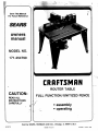
MODEL NO.
171.254790
iIffl
ROUTER TABLE
CAUTION:
READ ALL
NSTRUCTONS
CAREFULLY
FULL FUNCTION/UNITIZED. FENCE
Sold by SEARS, ROEBUCK AND CO., Chicago, DL 60684 U.S.A.
6107 1
MADE IN U.S.A.
Prhted in U.S.A. 4-92
WARNING: FAILURE TO HEED ALL SAFETY AND OPERATING INSTRUCTIONS AND WARNINGS REGARDING USE
OF THIS PRODUCT CAN RESULT IN SERIOUS BODILY INJURY.
GENERAL SAFETY INSTRUCTIONS FOR POWER TOOLS
1. KNOW YOUR POWER TOOL
Read the owner's manual carefully. Learn its application and limitations as well as the specific potential
hazards peculiar to this tool.
2. GROUND ALL TOOLS (UNLESS
DOUBLE INSULATED)
If tool is equipped with an approved 3-conductor cord
and a 3-prong grounding type plug, it should be plugged
into a three hole electrical receptacle. If adapter is used
to accommodate a two-prong receptacle, the adapter
wire must be attached to known ground, (usually the
screw securing receptacle cover plate). Never remove
third prong. Never connect green ground wire to a
terminal.
3. KEEP GUARDS IN PLACE
in working order, and in proper adjustment and
alignment.
12. USE SAFETY GOGGLES (Head Protection)
Wear Safety goggles (must comply with ANS Z871)
at all times. Also, use face or dust mask if cutting
operation is dusty, and ear protectors (plugs or muffs)
during extended periods of operation.
13. SECURE WORK
-
Use clamps or a vise to hold work when practical.
It's safer than using your hand, frees both hands to
operate tool.
14. DON'T OVERREACH
Keep proper footing and balance at all times.
15. MAINTAIN TOOLS WITH CARE
Keeps tools sharp and clean for best and safest performance. Follow instructions for lubricating and
changing accessories.
16. DISCONNECT TOOLS
4. REMOVE ADJUSTING KEYS
AND WRENCHES
Form habit of checking to see that keys and adjusting wrenches are removed from tool before turning
it on.
5. KEEP WORK AREA CLEAN
Cluttered areas and benches invite accidents. Floor
must not be slippery due to wax or sawdust.
6. AVOID DANGEROUS ENVIRONMENT
Don't use power tools in damp or wet locations or
expose them to rain. Keep work area well lighted.
Provide adequate surrounding work space.
7. KEEP CHILDREN AWAY
All visitors should be kept a safe distance from work
area.
8. MAKE WORKSHOP KID-PROOF
- with padlocks, master switches, or by removing
starter keys.
9. DON'T FORCE TOOL
It will do the job better and safer at the rate for which
it was designed.
10. USE RIGHT TOOL
Don't force tool or attachment to do a job it was not
designed for.
11. WEAR RIGHT APPAREL
Do not wear loose clothing, gloves, neckties or jewelry
(rings, wrist watches) to get caught in moving parts.
Nonslip footwear is recommended. Wear protective
hair covering to contain long hair. Roll long sleeves
above the elbow.
before servicing; when changinq accessories such as
blades, bits, cutters, etc.
17. AVOID ACCIDENTAL STARTING
Make sure switch is in OFF" position before plugging in.
18. USE RECOMMENDED ACCESSORIES
Consult the owner's manual for recommended accessories. Follow the instructions that accompany
the accessories. The use of improper accessories
may cause hazards.
19. NEVER STAND ON TOOL
Serious -injury could occur if the tool is tipped or if
the cutting tool is accidentally contacted.
Do not store materials above or near the tool such
that it is necessary to stand on the tool to reach them.
20. CHECK DAMAGED PARTS
Before further use of the tool, a guard or other part
that is damaged should be carefully checked to ensure that it will operate properly and perform its
intended function. Check for alignment of moving
parts, binding of moving parts, breakage of parts,
mounting, and any other conditions that may affect
its operation. A guard or other part that is damaged
should be properly repaired or replaced.
21. DIRECTION OF FEED
Feed work into a t,Iade or cuttor against the direction
of rotation of the blade or cutter only.
22. NEVER LEAVE TOOL RUNNING
UNATTENDED
Turn. power off. Don't leave tool until it comes to a
complete stop.
GENERAL SAFETY INSTRUCTIONS FOR THE ROUTER TABLE
WITH UNITIZED FENCE.
1. ALWAYS USE EYE PROTECTION
The operation of any power tool can result in foreign objects being thrown into the eyes, which can
result in severe eye damage. Always wear safety
goggles before commencing power.tool operation.
Safety goggles are available at Sears retail or catalog stores.
2. KEEP HANDS CLEAR OF BITS, AND WORKING
AREA
3. MAKE AND USE A PUSH STICK TO MOVE
SMALL WORKPIECES ACROSS THE CUTTING
AREA.
4. KEEP ROUTER CLEAN
AFTER EVERY USE, CLEAN SAW DUST OFF
THE ROUTER. (ALSO BLOW OUT INSIDE).
5. YOUR ROUTER TABLE IS PROVIDED WITH A
DUST COLLECTING ATTACHMENT. ALWAYS
USE SHOP VAC. FOR ALL ROUTING OPERATIONS REQUIRING USE OF FRONT SIDE OF
UNITIZED FENCE. (FRONT SIDE IS THE SIDE
WITH THE CRAFTSMAN LABEL).
NOTE: Motors used on wood-working tools are
particularly susceptible to the accumulation of sawdust and wood chips, and
should be blown out, or "vacuumed", frequently to prevent interference with normal motor ventilation.
6. CHECK FUNCTION OF GUARD BEFORE EACH
USE. REMOVE ALL DUST AND CHIPS FROM
GUARD AREA AS NEEDED TO MAINTAIN
GUARD FUNCTION.
7. NEVER PUT YOUR FINGERS UNDER THE
GUARD WHEN THE ROUTER IS PLUGGED IN.
8. ALWAYS USE THE ROUTER TABLEFENCE TO
GUIDE THE WORK. DO NOT WORK FREE
-HAND.
When using pilot type bits, keep the fences as close
to the pilot as possible to provide additional backup
and additional guidance and to avoid chances of
an accident and possible personal injury.
9. ALWAYS FEED AGAINST THE ROTATION OF
THE CUTTER WHEN ROUTING ON THE
ROUTER TABLE. FEED WORKPIECES IN THE
DIRECTION OF THE ARROW AS SHOWN ON
THE LABEL ON THE SIDE OF THE FENCE
BEING USED (WHEN FACING THE TABLE
FRONT).
10. FOR ALL EDGE CUTTING AND END CUTTING
OPERATIONS, USE FRONT SIDE OF UNITIZED
FENCE. USE BACK SIDE OF FENCE ONLY FOR
ROUTING OPERATIONS AWAYFROM EDGE
ON THE UNDERSIDE OF WORKPIECE SUCH AS
GROOVING; FLUTING; VEINING; CROWN
MOLDJNG ETC.
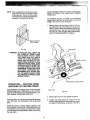
11. WHEN END CUTTING ON WORKPIECES 4"
WIDE OR LESS, CLAMP AND HOLD AND FEED
THE WORKPIECE WITH THE PUSH BLOCK
USING BOTH HANDS AS SHOWN IN FIG. #27.
KEEP FINGERS CLEAR OF BIT WHEN MOVING
WORKPIECE ACROSS THE CUTTING AREA.
NEVER PLACE YOUR HANDS LOWER THAN
THE TOP OF RETRACTABLE GUARD.
12. ROUTER BITS ARE EXTREMELY SHARP.
Be extra careful when working around them.
13. SOME ROUTERS WHEN USED IN AN UPSIDE
DOWN POSITION (SUCH AS ON A ROUTER
TABLE) WILL FALL (OR DROP) OUT OF THE
ROUTER BASE WHEN THE BASE CLAMP IS
LOOSENED. IT IS THEREFORE ABSOLUTELY
NECESSARY TO SUPPORT THE ROUTER
MOTOR FROM BELOW WHEN THE BASE
CLAMP IS LOOSENED TO MAKE ADJUSTMENTS, OR FOR ANY OTHER REASON.
14. ALWAYS LOOK UNDER THE TABLE AT THE
SWITCH WHEN TURNING THE ROUTE.R
ON/OFF AND TOUCH NOTHING BUT THE
SWITCH. NEVER REACH UNDER THE TABLE
WHEN ROUTER IS RUNNING FOR ANY OTHER
REASON.
NOTE: It is far more safe and convenient to use
a "Sears Craftsman 25182 Router Table
Switch Package". This switch provides a
key operated ON/OFF button which allows
very fast and easy access when and if it
becomes necessary to turn the router
"OFF" quickly. The key can be removed
to render the switch inoperable to unauthorized people.
15. ONCE BOTH GUARDS ARE INSTALLED FOR
ROUTING, DO NOT REMOVE THEM FOR ANY
REASON.
16. MOUNT ROUTER TABLE FIRMLY AND
SECURELY TO A WORK SURFACE BEFORE
USE. FAILURE TO DO SO COULD CAUSE
TABLE TO TIP OVER OR SLIDE DURING OPERATION RESULTING IN PROPERTY DAMAGE
AND/OR SERIOUS BODILY INJURY.
17.WARNING:
BEFORE MAKING ANY CUT, UNPLUG ROUTER
AND RETRACT GUARD TO MAKE ABSOLUTELY SURE THAT RETRACTABLE GUARD
CLEARS THE ROUTER BIT, AND THE GUARD
IS FUNCTIONING NORMALLY. SEE FIG. #19.
18. WARNING:
ROUTER VIBRATIONS SOMETIMES CAN
CAUSE FASTENERS FOR THE TABLE, THE
ROUTER AND ThE UNITIZED FENCE TO QET
LOOSEI PERIODICALLY CHECK FASTENERS
TO MAKE SURE THEY ARE TIGHT AND
SECURE.
INTRODUCTION
How often have you needed a large guiding surface on
a router table? Your Sears Craftsman Router Table with
Unitized Fence comes with:
A unique 4" high unitized fence designed to assist
for end grain routing for making tenons, sliding
dovetails and tongue and groove-joints along with
most edge and face cutting operations.
a.
b.
A specially designed push bloek with quick clamp
for back up and clamping boards up to 4" width for
end grain routing.
c.
An accurate and quick adjusting jointing fence
adjustable to proper jointing depth of cut.
d.
Reversing feature of unitized fence designed to
enable routing operations like grooving; fluting;
veining; crown molding etc. up to 2 1/2" away from
the edge towards the middle of the board.
e
Two guards for operation on either side of the unitized fence.
f.
Dust collecting attachment for most shop vac. hook
ups.
If order to facilitate handling and minimize any damage
that might occur during shipment, your new routertable
is packaged unassembled. We know you are anxious
to see what your new tool will do, but a few minutes
spent now carefully reading the following instructions,
will result in less frustration and more enjoyable operation later.
Start by checking and acôounting for all the loose parts.
If any parts are missing, contact your local Sears retail
or catalog outlet for replacement.
UNPACKING AND
CHECKING CONTENTS
Refer to Parts List on Page 16
WARNING
YOU MUST READ AND UNDERSTAND ALL THE INSTRUCTIONS COMPLETELY BEFORE ATTTING TO
ASSEMBLE AND OPERATE YOUR ROUTER! ROUTER TABLE.
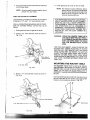
ASSEMBLY OF TABLE
6. Turn the table right side up and tighten all 16
screws and nuts with a screwdriver and wrench or
pliers.
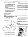
1. Turn the table upside down.
2. Place one of the table legs in one corner of the table
as shown in Fig. #1.
Leg
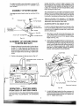
MOUNTING ROUTER TO TABLE
ALWAYS UNPLUG ROUTER BEFORE MOUNTING
(The table will accept Sears routers with bases up to
6" in diameter).
ATTACHING SEARS ROUTERS WITH THREE HOLE
BASE PLATES.
Table Top
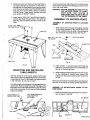
1. Remove the router base plate (back plate) from the
router.
2. While holding the router upside down, position it
to the underside within the center ring of the table
top as shown in Fig. #2.
#10-32 x 5/8"
Pan Head Screw
#10-32 Hex Nut
#10 Lock Washer
Fig. #1
3. Insert the 10-32 x 5/8 machine screws through the
table top and leg.
4. Lightly tighten the nuts and lock washers on each
screw. The lock washers should be against the
inside of the leg.
Center Ring
5. Repeat for the remaining three legs.
3. Rotate the router until the three mounting holes in
the router base line up with three of the holes in
the table top. (It will be helpful if you orient the router
such that you can easily reach the ON/OFF switch
from the front of the table. Sears Craftsman
25182 Router Table Switch Package provides
easy access to ON/OFF button).
To remove the insert, place the point of a small screwdriver into the slot (with the small tang) and pry the insert
out of the router table.
WARNING: BEFORE ASSEMBLING AND ATTACHING UNITIZED FENCE TO TABLE,
MAKE SURE THAT ROUTER IS
UNPLUGGED AND THE BIT IS BELOW
THE TOP SURFACE OF THE TABLE.
4. Insert three #10-32 x 3/8" long flat head machine
screws (provided) throUgh holes in the table top
(See Fig. #3) and tighten securely into the router
base.
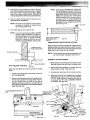
ASSEMBLY OF UNITIZED FENCE
ASSEMBLY OF JOINTING FENCE TO UNITIZED
FENCE
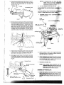
1. Slide jointing fence through rectangular opening
in the cavity provided on the unitized fence (ribs
on the unitized fence will slide in the grooves on
the underside of jointing fence). See Fig. #5.
9/32"I.D.x3/4" O.D.
- 1/4-20 Knob (small)
rii vvasnr
Unitized Fenc
Fig. #5
2. Insert 1/4-20 x 1" long flex head bolt through the
hole in the unitized fence (fron the underside) and
the slot in the jointing fence.
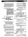
SELECTING AND INSTALLING
TABLE INSERTS
3. While holding the head of the bolt in the hex recess
on the underside of unitized fence, place a flat
washer over the bolt and screw small 1/4-20 knob
on bolt.
With the desired bit in the router, select a table insert
which has a center hole slightly larger than the diameter
of the router bit. Note: For bits larger than approximately
1 3/8" diameter, do not use an insert.
When knob is loosened, the jointing fence can slide back
and forth in the cavity for proper jointing adjustment.
The table inserts were designed to be snapped into the
router table. Slide the large tang under the edge of the
large hole in the router table as shown in Fig. #4. Using
your thumb, press down on the insert until the small tang
snaps into position.
ASSEMBLY OF RETRACTABLE GUARD TO UNITIED FENCE
1. Place the unitized fence upside down on a flat surface as shown in Fig. #6.
Use Thumbs Pressure to
Snap TaIeinsert
Into Position
Use Screwdriver to
Remove Table Insert
.iLA
Hex Recess
-
-
,--
',.
riy,
NOTE: If the guard does not retract o
loosen screw just enough unt]
es
retract out freely and snaps bc normal forward position by itself.
6. Turn the unitized fence right side up.
2. Orient the retractable guard as shown in Fig. #7.
Position and hold the spring over its hub such that
formed end of spring wraps over the guard as
shown in Fig. #7.
Straight Leg
Spring
Retractable Guard
ATTACHMENT OF UNITIZED FENCE ASSEYTO
TABLE
ALWAYS UNPLUG ROUTER BEFORE A1TACNG
FENCE TO AND REMOVING FROM TABLE
1. Assemble unitized fence assembly t
shown in Fig. #10.
e as
1/4-20
Large Knob
3. While holding the spring over the hub and formed
end over the guard, position and press the straight
leg of spring against surface 'X' to align hole in hub
over boss on unitized fence (see Fig. #8). Slip the
guard over the boss. Spring will now be trapped
between the guard and the fence. (Spring diameter
is bigger than the hub diameter. You will need to
use both hands to hold spring in proper position).
9/32" l.D. x 3/4" O.D.
Flat Washer-...
Slot
Straight Leg of Spring
. Surface 'X'
Router
Fig. #10
Fig. #8
4. Tightly secure retractable guard in place using self
threading #8-10 x 9/16" long pan head plasform
screw and a flat washer as shown in Fig. #9.
2.. Insert one of the 1/4-20 x 1 3/4" long hex headbolts
through the hole in the table top (from the underside) and the slot in the fence.
5. Swing 9uard a few times in the direction of arrow
to see that it retracts out freely by itself and returns
to its normal position over the router table hole. See
Fig. #9.
3. While holding the head of the bolt in the hex recess
on the underside of the tabletop, place a flat washer
over the bolt and install a large 1/4-20 knob onto
the bolt to loosely secure the fence.
Unitized Fence
4. Repeat for, the other slot.
NOTE: The unitized fence assembly can be
attathed to table with either side facing the
front To use other side, just remove the
kacbs and turn the fence around.
ASSEMY OF P13S14 BLOCK
Screw tie srraU end of clamp rod into threaded
ap rate until the plate bottoms on its
(make sure clamp plate is oriented such
tteC' is facing outwards as shown in Fig.
3/16" l.D. x 1/2" O.D.
Flat Washer
6
2. Tightly secure clamp plate to clamp rod using 1/4"
helical lock washer and a hex nut.
3. Insert the opposite threaded end of clamp rod
through hole in push block and install a flat washer
and a wing nut on to it. See H. #11.
5/16-18" Wing Nut
NOTE: a.
Remove dust and chips from sliding surfaces of push block and unitized fence as
needed to maintain good sliding motion.
b.
Occasional application of furniture spray
wax on sliding surfaces of PUSH BLOCK
ONLY will greatly improve the sliding
motion.
FOR ROUTING ON ENDS (TENONS, SLIDING DOVETAILS, ETC.) WORKPIECE IS HELD AGAINST FACE
OF UNITIZED FENCE AND CLAMPED BETWEEN
CLAMP PLATE AND SURFACE '5' OF PUSH BLOCK.
SEE FIG. #12a.
1/4" Helical Lock Washer
Small End
Shoulder
Clamp Plate
Fig. #11
1/4-28 Hex Nut
WARNING: ROUTER VIBRATIONS SOMETIMES CAN CAUSE 1/4-28 HEX
NUT AND CLAMP PLATE TO GET
LOOSE! PERIODICALLY CHECK
FASTENERS AND CLAMP PLATE
TO MAKE SURE THEY ARE TIGHT
AND SECURE.
Clamp Plate
MOUNTING PUSH BLOCK ASSEMBLY ON UNITIZED
FENCE
/1
Clamp plate when free, tries to swing in the direction
of arrow (See Fig. #12a) due to its weight.
Face of Unitized Fence
Fig. #12b
ASSEMBLY OF GUARD TO UNITIZED FENCE
1. Assemble guard to unitized fence as shown in Fig.
#13.
2. While holding the guard at a slight.angle as shown,
insert tab on one side of guard into hole inside the
slot on fence.
3. Hold the guard against this slot, straighten it into
a vertical position and; insert the opposite tab into
the mating slot. See Fig. #13.
Fig. #12a
1. Mount push block assembly on the unitized fence
by supporting clamp plate against the face of the
fence (Fig. #1 2b) and aligning retaining rib on push
block with the groove in the face of unitized fence.
See figures #12a and #12b.
2. Slide push block assembly back and forth along
entire length of unitized fence to see that it slides
freely.
7
4. Pivot guard back and forth a few times to make sure
that it moves freely.
NOTE: Once the guard has been installed, do not
remove it for any reason.
_4.
guard and let it rest on the vac hose.
NOTE: For maximum suction efficiency, stick a
piece of tape or use a piece of scrap wood
to cover up the opening in the rear of the
fence as shown in Figures 14a and 14b.
Uncover opening after use.
DUST COLLECTING ATTACHMENT
Unitized fence is provided with a hookup for most Sears
Craftsman 2 1/2" and 1 1/4" hose diameter vacs.
FOR ALL OPERATIONS REQUIRING USE OF FRONTSIDE OF UNITIZED FENCE, connect shop vac as
follows:
1. Raise guard and lean it against the fence.
2. Attach 2 1/2" hose diameter nozzle as shown in
Fig. #14a.
FOR OPERATIONS REQUIRING USE OF BACKSIDE OF UNITIZED FENCE, DO NOT CONNECT
SHOP VAC. AS IT WILL HINDER OPERATION.
• THE BACKSIDE OF FENCE IS ONLY FOR CUTTING OPERATIONS ON THE UNDERSIDE OF
WORKPIECE. THE WORKPIECE DURING SUCH
OPERATIONS COMPLETELY COVERS THE
ROUTER BIT AND THE DUST CANNOT BE
VACUUMED.
WARNING: OPERATING ROUTER TABLE WITHOUT USE OF SHOP VAC. MAY RESULT
IN EXCESSIVE COLLECTION OF SAW
DUST AND CHtPS UNDER THE FENCE
AND THE RETRACTABLE GUARD
AREA.
FOR YOUR OWN SAFETY, ALWAYS UNPLUG THE
ROUTER AND CHECK FUNCTION OF GUARD
BEFORE EACH USE. REMOVE DUST AND CHIPS
FROM GUARD AREA AS NEEDED TO MAINTAIN
GUARD FUNCTION. KEEP WORK AREA CLEAN.
REMOVE UNITIZED FENCE FROM TABLE (MAKE
SURE ROUTER IS UNPLUGGED) TO CLEAR DUST
AND CHIPS TRAPPED BETWEEN FENCE AND
TABLE TOP.
Tape
Fig. #14a
3. Attach 1 1/4" hose diameter nozzle as shown in
Fig. #14b.
MOUNTING THE ROUTER TABLE
THE ROUTER TABLE MUST ALWAYS BE FIRMLY
AND SECURELY MOUNTED TO A WORK SURFACE
BEFORE USE. FAILURE TO DO SO COULD CAUSE
TABLE TO TIP OVER OR SLIDE RESULTING IN
PROPERTY DAMAGE AND/OR SERIOUS PERSONAL
INJURY.
Each leg has (2) holes at the bottom for mounting. Firmly
secure router table to work surface using appropriate
fasteners (not provided) as shown in Fig. #15.
WHEN ROUTING, ALWAYS FEED AGAINST THE
ROTATION OF THE CUTTER. FEED WORKPIECE IN
THE DIRECTION OF ARROW AS SHOWN ON THE
LABEL ON THE SIDE OF THE FENCE BEING USED
(when facing the table front).
For added versatility, secure the table to a piece of 1/2"
or thicker plywood which can be "C" clamped to your
vork surface.
ASSEMBLY OF M1ER GAUGE
The unitized fence on your table is provided as a guide
against which the workpiece should be held for accuracy
in rQuting. Free hand routing (not holding work against
the fence) is hazardous and should be strictly avoided.
Assenije protractor head to miter bar as shown in Fig.
#16.
Shop vac. with either 2 1/2" diameter or 1 1/2" diameter
hose nozzle should be connected to the dust collection
attachment when using the router table.
ADJUSTING DEPTH AND HEIGHT OF CUT
In order to retract the guard and have full access to the
router bit for making adjustments, select a board that
is smooth with its edges and ends true to each other
and its surfaces and:
-
3/16" Dia.x518"
Grooved Pin
(Assembled)
1. Mark lines 'A' and 'B' on the end of this board. Line
'A' for desired depth of cut (amount of material you
want to remove) and line 'B' for desired cutting
height. See Fig. #18,
Fig. #16
2. Clamp this board against the face of the fence with
edge resting on table top and end marked with lines
'A' and 'B' close to the bit. See Fig. #18 (This will
retract guard inside fence and provide access to
the bit for making adjustments. MAKE SURE
ROUTER IS UNPLUGGED WHEN CLAMPING
BOARD AND MAKING ADJUSTMENTS).
ALIGNMENT OF UNITIZED FENCE
TO MITER BAR SLOT
1. Measure distance from each end of unitized fence
to edge 'E' of miter bar slot on the table as shown
in. Fig. #17. If both distances are the same, the
fence is parallel to miter bar slot. If not, loosen large
knobs and adjust fence accordingly. Tighten both
knobs.
Large Knobs
2. PoSition miter gauge on table as shown in Fig. #17.
(Retractable Guard not Shown for
Clarity).
Scale
Outermost Cutting Ec
Fig. #17
Fig. #18
OPERATION - ROUTING USING
FRONTSIDE OF UNITIZED FENCE
3. Loosen both large knobs that allow movement of
fence and move fence forward and backward until
outermost cutting edge of router bit is aligned with
line 'A'. Tighten both knobs.
ALWAYS UNPLUG THE ROUTER BEFORE MAKING
ANY SETTING, ADJUSTMENTS, OR CHANGING
BITS.
9
described before. (MAKE SU
UNPLUGGED WHEN MAKING
4. Raise or lower the router until top cutting edge of
bit is aligned with line 'B'. (Refer to your router's
owner's manual for adjusting your router properly)..
AFTER MAKING THIS ADJUSTMENT, BE SURE
ROUTER IS SECURELY TIGHTENED IN THE
ROUTER BASETHE BIT IS SECURELY TIGHTENED IN THE ROUTER CHUCK, AND ROUTER
BASE IS TIGHTLY SECURED TO TABLE TOP.
3. Check your adjustments byturnL:iand feeding a piece of scrap woc: a
beyond router bit. Then stop and t-
4. Loosen knob on jointing fence and movelt out,
flush against the finished edge of scrap wood.
Retighten the knob. See Fig. #20.
(Retractable Guard not
Clarity)
Small Knob on
Jointing Fence
Fig. #20
' Finished Edge
5. Repeat the test cut on the scrap wood.
Fig. #19
NOTE: For best jointing results, take very shallow
cuts - 1/32" or less.
USING ROUTER TABLE FOR EDGE CUTTING WITH
NON-PILOTED BITS
USING ROUTER TABLE AS JOINTER (FULL EDGE
CUTTING)
1. Position the jointing fence such that its face is flush
with the face of unitized fence. Tighten small knob
on jointing fence. See Fig. #21.
For maximum strength and accuracy, boards to be
jointed together should be smooth and true. The edges
should be true to the workpiece surface. You can true
the edges on your router table using a straight bit.
NOTE: The jointing fence provides a continuous
support for the workpiece, as it is fed
beyond the router bit. It compensates for
the gap created by the removal of material by the router bit.
Table Front
6. The router table is now ready for use.
NOTE: The procedure described above is
intended to provide a way of retracting and
holding the guard to have full access to the
router bit for making adjustments. Workpiece to be routed could be substituted for
the scrap board for making adjustments.
1. Check to see if face of jointing fence is flush with
the face of unitized fence. If not, loosen small knob
on jointing fence and push jointing fence inside the
cavity in unitized fence. Tighten knob on jointing
fence.
-3N'
NOTE: Feed work in the direction of awn
on label on the frontside of unittze
ce
(when facing table front).
5. Remove the board from the fence.
WARNING: WHEN ADJUSTING HEIGHT OF
ROUTER BIT FOR ANY DESIRED
CUT, MAKE ABSOLUTELY CERTAIN THAT TOP OF BIT IS BELOW
THE INSIDE SURFACE OF
RETRACTABLE GUARD AS
SHOWN IN FIG. #19. CHECK TO
SEE THAT GUARD RETRACTS
FREELY IN AND OUT OF FENCE TO
ITS NORMAL POSITION OVER THE
ROUTER TABLE HOLE. DO NOT
OPERATE ROUTER IF ANY PART
OF THE BIT CONTACTS THE
GUARD.
IS
T.TS).
Small
Jointing Fence
Flush with
Unitized Fence.
2. Adjust depth of cut (material you want to remove)
and router bit height as described before for Fig.
#18. Tightly secure the fence and the router as
t
10
Retractable Guard
Fig. #21
Table Front
NOTE: If you have purchased RAIL AND STILE
CUTTERS (Sears Craftsman 21 257) for
making cabinet door frames on your router
table, MAKE SURE THAT FRAME THICKNESS is not more than 3/4". If frame thickness is more than 3/4", the top of the bit,
as shown in Fig. 'A' of Rail and Stile Cutters instructions, will interfere with retractable guard on your unitized fence. See Fig.
#24 and Fig. #19.
2. Adjust depth of cut (material you want to remove)
and router bit height as described before. Tighten
both large knobs to lock fence on table. Tightly
secure the router. (MAKE SURE ROUTER IS
UNPLUGGED WHEN MAKING ADJUSTMENTS).
3. Test cut a piece of scrap wood to make sure your
adjustments are satisfactory.
NOTE: Feed work in the direction of arrow shown
on label on frontside of unitized fence
(when facing table front).
- Top of Bit
4. The router table is now ready for use.
NOTE: If you have purchased a MOLD MAKER
BIT SET (Sears Craftsman 21 255) for
making moldings on your router table, set
the unitized fence in EDGE CUTTING
MODE for making the first cut on your
workpiece using Bit #25527. See Fig. #22.
Door Frame Thickness
Must Not Be More
than 3/4"
Fig. #24
U
USING ROUTER TABLE FOR END CUTTING
When routing on ends of workpiece for making tenons,
sliding dovetails and tongue and groove joints, the workpiece must be made smooth with both edges and ends
made true to each other and its surfaces.
NOTE: The push block and clamp plate assembly will
not accommodate workpiece wider than 4".
EXAMPLE: CUTTING TENONS
1. Make certain that jointing fence is locked in position with its face flush with that of unitized fence.
WITH PILOTED TYPE BITS
Fig. #22
2. Mount push block assembly on unitized fence as
shown before in Figs. #12a and #12b.
When bits with pilots are used to control the cutting
depth:
3. Install proper table insert into the table top hole.
1. Position the jointing fence in the same manner as
with non-piloted bits.
4. Mark lines 'A' and 'B' on the edge of the workpiece
close to the end to be out. Line 'A' for FULL DEPTH
OF CUT (total amount of. material you want to
remove) and line 'B' for FULL DESIRED HEIGHT
OF TENON. See Fig. #25.
2. Move the unitized fence back only enough to permit the pilot to control the cutting depth. Positioning the unitized fence as close to the pilot as
possible will serve as a back-up, and will help prevent chances of an accident, and possible personal
injury. See Fig. #23.
Wing Nut
Workpiece Side Flush
Against Face of
Unitized Fence
Fig. #23
Table Front 11
Fig. #25
Push Block
Outermost
Cutting Edge
Max. Width 4"
'Edge of Table Top Hole
egh to clamp
ZVERTlGHTEN5iding in the
:zhich in turn
Y-s dxsteps in the
-acut See Fig.
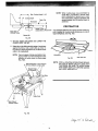
WARNING: DO NOT SET DEPTH OF CUT
MORE THAN 3/8" (FIG. #26). IF
DEPTH OF CUT IS MORE THAN
3/8", THE EDGE 'E' OF WORKPIECE WHEN SLIDING ACROSS
WILL INTERFERE WITH PORTION
'P' OF GUARD. THE GUARD THEN
WILL NOT RETRACT INSIDE
FENCE AND HENCE YOU WILL
NOT BE ABLE TO SLIDE WORKPIECE ACROSS THE BIT TO MAKE
THE CUT. SEE FIG. #27.
'k
aust unitized
fean
a cied with line
with line
'A' and top cti:
cc
B'.SeeFig.#25.Ti-i. saceandthe
roderasdescbedbec-J3T\3 DEPTH
AND HEIGHT OF CUT.
7. Slidepushbckandtherefore.c:cebackto
let guard swing out to its normai poion as shown
in Fig. #27.
8. Turn router and shop vac 'ON'. While holding push
block and GUIDING WORKPIECE AGAINST
FENCE with both hands (Fig. #27) and FINGERS
AT SAFE DISTANCE ABOVE GUARD AND SPINNING BIT, feed workpiece across the bit to make
FULL DEPTH OF CUT IN ONE PASS. (DO NOT
STOP FEED UNTIL WORKPIECE IS FAR
ENOUGH BEYOND SPINNING BIT TO ALLOW
GUARD TO RETRACT OUT FULLY TO ITS NORMAL POSITION).
Fig. #26
NOTE: Clamp and test cut a piece of scrap wood
to check your adjustments before making
your finished cut.
9. Turn router and shop vac 'OFF'. Unclamp workpiece, and slide push block back.
10. Position and clamp the opposite side of workpiece
in the same manner as described in Step #5 (make
sure the wing nut is tight just enough to clamp workpiece in position and end to be cut is resting on the
edge of table top hole). Repeat steps #7, #8, and
#9.
11. To cut ends of the tenon., position and clamp workpiece in the same manner as in step #5 above
except edge of workpiece should be held flush
against face of fence and end to be cut should be
resting on edge of table top hole. See Fig. #28.
Repeat steps #7, #8, #9, and #10.
Edge of Workpiece Flush Against
Face of Unitized Fence
5. Position workpiece between clamp plate and push
block such that its side is held flush against face
of the unitized fence, the end to be cut is resting
on the edge of the table top hole and edge marked
with lines 'A' and 'B' is facing the router bit. Clamp
workpiece in this position by snugly tightening the
wing nut on clamp rod while making sure that
clamp plate stays oriented on workpiece as shown
in Fig. #25. (This will retract guard inside the fence
and provide access to the bit for making adjustments. MAKE SURE ROUTER IS UNPLUGGED
WHEN POSITIONING AND CLAMPING WORKPIECE AND MAKING ADJUSTMENTS).
12
Edge of Table Top Hole
DO NOT CONNECT SHOP VAC. WHEN USING BACKSIDE OF FENCE. THE HOSE WILL HINDER
OPERATION.
NOTE: When cuffing tenons, always clamp workpiece with end to be cut resting on edge
of table top hole. This will minimize steps
in finished tenon surface (Fig. #29) due to
variations in the table top flatness.
For maximum accuracy, one edge of your workpiece
(edge sliding against the fence) must be true and
straight. Set up your fence as follows:
1. Remove both large knobs and 1/4-20 x 1 3/4" 1g.
hex head bolts, turn the unitized fence around and
attach it back to table with backside of fence facing the table front. See Fig. #30. (MAKE SURE
ROUTER IS UNPLUGGED WHEN REMOVING
AND ATTACHING FENCE TO TABLE).
Steps in Finished
Tenon Surface
Fig. #29
WARNING: ALWAYS CUT FULL DEPTH ON
ALL 4 SIDES OF TENON IN ONE
PASS ACROSS THE BIT. ONCE
THE SIDES ARE CUT AND IF
STEPS OR OTHER IMPERFECTIONS ARE NOTICED ON FINISHED TENON SURFACE, CLEAN
THEM WITH WOOD CHISEL, SAND
PAPER OR FILE, ETC. DO NOT TRY
TO CLEAN THEM BY RE-SETTING
WORKPIECE ON ROUTER TABLE
AND FENCE. WORKPIECE MAY
INTERFERE WITH GUARD (SEE
FIGS #27 ABOVE) WHICH IN TURN
WILL PREVENT IT FROM SLIDING
ACROSS THE BIT.
OPERATION - ROUTING USING
BACKSIDE OF UNITIZED FENCE
USE BACKSIDE OF FENCE ONLY FOR ROUTING
OPERATIONS AWAY FROM EDGE ON THE UNDERSIDE OF WORKPIECE SUCH AS GROOVING; FLUTING; VEINING; CROWN MOLDING, ETC.
Table Front
Fig. #30
2. Raise guard and let it lean against the fence.
ALWAYS UNPLUG THE ROUTER BEFORE MAKING
ANY SETTING, ADJUSTMENTS, OR CHANGING
BITS.
3. Position the fence behind the router bit for the
desired cutting depth (the distance of the cut from
the edge of the workpiece, as shown in Fig..#31)
WHEN ROUTING ALWAYS FEED AGAINST THE
ROTATION OF THE CUTTER. FEED WORKPIECE IN
THE DIRECTION OF ARROW AS SHOWN ON LABEL
ON THE SIDE OF FENCE BEING USED (when facing
the table front).
13
NOTE: When routing deep cuts (controlled by
router bit) in a workpiece, remove material in increments to prevent your router
from overloading. Repeat operation with
several passes until the desired depth is
achieved.
Max. Cutting Depth 2 1/2"
Table Top
PROTRACTOR
Depth of Cut
(Controlled by Router Bit)
Back Side of
Unitized Fence
Your protractor wilt serve as a handy aid when extra support is needed for routing small workpieces or ends of
large workpieces. See Fig. #33.
Router Bit
Fig. #31
4. Securely tighten both knobs and LOWER THE
GUARD OVER THE BIT.
5. Make the cut by sliding straight edge of workpiece
against the fence. Use a push stick as shown in
Fig. #32. (For each successive cut, the fence would
need to be readjusted).
NOTE: Test cut a piece of scrap wood before making your finish cut. Feed workpiece in the
direction of arrow shown on fence label
(Fig. #32).
Fig. #33
Miter Bar Slot
NOTE: FOR ALL ROUTING OPERATIONS REQUIR ING USE OF MITER GAUGE ALONG WITH
THE FENCE, BE SURE TO ALIGN FENCE
WITH MITER BAR SLOT BEFORE MAKING
ANY CUTS. SEE FIG. #17.
Feed Workpiece in the Direction
of Arrow Shown o this Label
Fig. #32
14
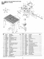
PARTS UST FOR CRAFTSMAN ROUTER TABLE
OOEL NO. 171.254790
8
39.
22
Key
No.
Part No.
Key
No.
Quan.
Description
Part No.
Description
Quan.
1
21
29L-648
Push Block
- 1
4
22
29L-651
Clamp Rod
1
Flat Washer 9/32 ID x 3/400
3
23
291-652
Clamp Plate
1
F29A-489 3
He r*øölt 1r4-2o
g
2
24
F 29A 246-12
Hex Hd Bolt 1/420 x 1
5 '
F29A 2422
-1ex Mach Screw Nut #1O.2
17
25
29L 654
Spring
1
6
31L 559
MIter Bar
1
26
F 29A 252-8
Wing Nut 5/16-18
1
1
1
'31L-431
Router Table Top
2
31L-429
Table Leg
3
F29A306-14
4
.
Ig
1
7
31L 438
Pointer
1
27
F 29A 306-27
5/16 FIat Washer
8
F29A 264-8
Pan Hd Mach Screw #10-32 x 5/16
1
28
29A 264-7
Pan Hd Mac'i Screw #10 32 x 5/8 Ig
16
1/4 Lock Wasber {Helical)
1
1
9
29L 183
Grooved Pin 3/16 dia x 5/8 type D
1
29
F 29A 3273
10
29L 293
Protractor Head
1
30
F 29A 306-26
#8 Flat Washer 316 I 0 x 1/2 0 D
11
31L 560
Knob
1
31
F 29A-653
#8-10 x 9/16 Lg Pan Hd Plasform Screw
.12
29L 202
Plastic Insert
5
32
29L 660
1/420 Knob (large)
2
1
*13
14
29A-298-13
Flat Hd. Mach. Screw #10-32 x 3/8
3
33
29L-659
1/4-20 Knob,(small)
29A509-1
#10 Lock Wasfier
16
34
45A 289
Label (Self Adhesive)
1
15
29A 306 15
#10 Flat Washer
1
35
45A 290
Label (Self Adhesive)
2
16
29A 310-5
Carriage Bolt #10-24 x 3/4 Ig
1
36
45A 297
Label (Self Adhesive)
1
17
29L-646' '
Unitized Fence
1
37
29L-65&
VacUum Hose Reducer
1
18,
29L-650-
Guard
1
38'
F29A-242-8
Hex Nut 1/4-28
1
19
29L-647
Guard (Retractable)
1
39
45A 292
Label (Self Adhesive)
1
20
291 649
Jointing Fence
1
-.
'
.
.
.
___________________________________________________ ____________
* Hardware item - may be purchased Ipcally.
16
WARNING: FAILURE TO HEED ALL &SSEMLY, SAFETY, AND OPERATININSTRUCTIONS AND WARNINGS REGARDING THE
USE OF THIS PRODUCT, ALONG WITH THOSE OPERATING INSTRUCTIONS AND WARNINGS IN'THE ROUTER AND THE ROUTER
TABLE OWNER'S MANUALS, CAN RESULT IN SERIOUS BODILY INJURY.
iAR / CRRFTMAK
GENERAL: The Router Table Extensions are used with
• the 25443, 25444, 25475 and 25479, Router Table. The
extensions increase the length of-the router table resulting in a larger work surface, allowing convenient additional support when routing lorigworkpieces.
The extensions CANNOT be used with the 25457 and
25473, Router Tables.
Eight screws, nuts, and lockwashers are packaged with
this product which are necessary when assembling the
extensions to the -25475, Router Table.
• They are NOT used with• the 25443, 25444, and 25479
Router -Tables because those Router Tables come with a
sufficient quantity of fasteners to permit the assembly of
- the extensions to those Router Tables while the 25475
does not.
-.
NOTE: If your Router Table has not been assembled yet,
proceed to the following section, ASSEMBLING THE
EXTENSIONS TO THE ROUTER TABLE. If your Router
Table has already been assembled and used proceed as
follows:
• a..
SQNECT THE POWER CORD TO THE ROUTER
•FROM.THE ELECTRICAL OUTLET.
- b. Remove any router bit that is now in the router.
c. -Lower the rQuterso the router bit chucking nut is below
the top surface of the table.
- d. Remove all accessories, such as guards, miter gauge,
and fences from table.
. e. Place the table,- top side down, on a flat surface and
disassemble the four legs from the table by removing
- the screws, nuts, and WaSbersthat hold the legs in
• place, f. Proceed to the following section.
ROUTER TABLE
EXTENSIONS
NOm 25211
2. MAKE SURE ALL SCREWS AND NUTS ARE
SECURELY TIGHTENED
3. Turn the tble top side up and check to see that the
extensions are even with or slightly below the table top.
'IN NO 'CASE SHOULD THE EXTENSIONS BE
HIGHER THAN THE TOP OF THE TABLE OR ELSE
THEY MAY INTERFERE WITH THE WORKPIECES
DURING -ROUTING CAUSING A CONDITION THAT
CAN RESULT IN POSSIBLE SERIOUS INJURY.
4. If the extensions are-hkgher than the top o the table,
loosen the screws holding the extensions afld reposition them so they are even with or slightly lower than
the top of the -table. SECURELY TIGHTEN ALL
SCREWS AND NUTS ONCE AGAIN. -5. To double check, slide a flat piece of wood along the
top of the table in both directions. Make sure that the
end of the wood moves freely without contacting the
edge of the extension next to the table.
6. Continue with assembly of the Router Table as described in the Owner's Manual or reassemble the accessories and guards previously removed.
WARNING: DO NOT PLACE HEAVY OBJECTS OR
PRESS HEAVILY ON THE EXTENSIONS OR ELSE
THEY MAY BE DAMAGED CAUSING A CONDITION
THAT CAN RESULT IN POSSIBLE SERIOUS BODILY
INJURY DURING ROUTING.
ASSEMBLING TETENSONS TO THE ROUTER
Rifr to the'section in your Router Table Owner's Manual
concerning the assembly of the legs to the table.
1. To assemble the Table Extensions to the Router Table,
place the table, top side'down, on a smooth, flat surface, and position the Table Extensions relative to the
table as show. Now follow the procedure for assembling the legs to the table, in the .Owner's Manual,
making sure to tighten tPie Screws marked "A" first
followed by the screws-marked "B". The screws, that
normally just hold the legs to the table, will now also
hold the extensions on the table.
I
Sold by SEARS, ROEBUCK AND CO.,
60923
Chicago, IL 60684 U.S.A.
MADE IN U.S.A.
4-92