1
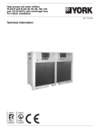
Heat pumps and water chillers,
YLCC-H and YLCC-42, 62, 82, 102,
122 and152 (R-407C)
condensed by air, with centrifugal fans
For indoor installation
Ref.: N-27362 0208
Technical Information
� � � � � � � �
������������
���������
��������
���������������������
����������
Johnson Controls Manufacturing España, S.L. is participating in the EUROVENT Certification
Program.
Products are as listed in the EUROVENT Directory of Certified Products, in the program AC1,
AC2, AC3, LCP and FC.
The LCP program covers air condensed water chillers and heat pumps of up to 600 kW.
Index
Page
General description
3
- Nomenclature
- General characteristics
3
3
Technical specifications
3
- Mechanical specifications
3-4
- Controls
4
- Accessories
4-5
- Physical data and electrical characteristics
6-7
- Limits of use
8
- Limits of use, YLCC
8
- Limits of use, YLCC-H
8
- Test conditions
8
- Nominal flows, cool only
8
- Nominal flows, heat pump
8
- Electrical characteristics
8
- Cooling capacities
9 - 12
- Heating capacities13 - 14
- Hydraulic circuit flow/pressure
characteristics of YLCC and YLCC-H units15 - 16
- Fan performances17
- Correcting factors18
- Factors with water and glycol18
Installation instructions19
- General information19
- Inspection19
- Enviromental protection19
- Warning signs19
- Transportation19
- Clearances
20
- Drainage
20
- Locating and securing the unit
20
- Hydraulic connections
21
- Hydro kits GH
22
- Circulation pump
22
- Flow switch
22
- Application on YLCC/YLCC-H units
22
- Wiring
23
- Wiring diagrams
23
Operating instructions decription of
YLCC and YLCC-H 42 to 102 control system
- Standard components
- General wiring diagram
- Display symbols
- Functions of keyboard
- Location of controls
- Table of parameters
- Table of alarms
24
24
25
26
26
27
27 - 35
36
Page
- Alarm reset
- Forced defrost (heat pump)
- Clearing hour counters
- Pump operation
- Calibration of probes
- Remote ON/OFF
- Remote HEAT/COOL
36
36
36
36
36
36
36
Description of YLCC and YLCC-H 122 to
152 control system
37
- Standard components
- General wiring diagram
- Display symbols
- Function of keyboard
- Location of controls
- Table of parameters
- Table of alarms
- Alarm reset
- Forced defrost (heat pump)
- Clearing hour counters
- Pump operation
- Calibration of probes
- Remote ON/OFF
- Remote HEAT/COOL
Accessories
37
38
39
39
40
40 - 48
49
49
49
49
49
49
49
49
50
- Remote terminal
- Wall mounting
- Electrical connections
- Installation
- Info mode
- RS485 serial line connection
- Assembly - Programmable key
- Download of unit program to the key
- Upload of key program to the unit
- LED messages
Operation
50
50
50 - 51
51
51
52
52
53
53
53
53
- Summer cycle YLCC
- Cooling cycle YLCC-H
- Heating cycle YLCC-H
54
54
54 - 55
General dimensions
56 - 60
Wiring diagrmas
61 - 80
Table of parameters, symbols and alarms
Temperature tables
54
81
82 - 83
General description
The YLCC water chillers and YLCC-H heat pumps are supplied factory-assembled and with all refrigerant piping and interconnecting wiring ready for installation at the job site. After
assembly, the water chillers go through a water test. Possible
leaks are also checked once the refrigerant is charged.
The units are made of galvanized steel with anticorrosive nuts
and bolts. The panels can be removed for access to internal
components. The outer galvanized steel parts are painted
with oven-dried enamel (RAL 9002).
Throughout the entire manufacturing process, all our products follow a quality control process in accordance with the
ISO 9001 standard, which is also demanded of the acquired
components. The DEP pressure equipment directive is also
applied.
The water chillers or air-water type heat pumps are designed
to be installed in air conditioning systems or industrial processes that require cold (or hot) water, or water and glycol.
Designed for indoor installation.
Nomenclature
ROCA unit
Liquid chiller
Centrifugal fan
Heat pump
Model
Vertical air discharge
- Two independent circuits (2 stages up to 102) (4 stages
122 and 152).
- Scroll compressors.
- Centrifugal fan (horizontal or vertical air discharge).
- Coaxial exchanger.
- R-407C refrigerant.
- Hydro kit (option).
The accessibility of all components and control system allows quick installation and start-up, as well as trouble-free
maintenance.
Technical specifications
Mechanical specifications
Casing
Made of zinc-coated aluminium steel sheeting, finished
with oven-polymerised powdered paint, colour RAL 9002.
Its extraordinary protection against corrosion, along with its
heavy duty internal structure, make up an extremely robust
and resistant unit.
Compressor
The hermetic Scroll type compressor is protected internally.
Starting will be direct on line. With electronic control. The
sump heater is activated when the compressor is inoperative.
Mounted on anti-vibratory supports.
Reversible indoor exchanger
Coaxial type exchanger, of a large transmission surface,
made of finned tubing. Insulated externally.
Maximum operating pressure is 25 bar on the refrigerant
side, and 10 bar on the water side.
Outdoor exchanger
Of a large surface. Made of copper tubing in staggered
rows, mechanically expanded within high performance aluminium fins. Maximum operating pressure of the coil is 28
bar (standard unit).
Control of refrigerant to the exchangers
Refrigerant feed is carried out by means of an expansion
valve with external pressure equalizer (reversible on heat
pump models).
Refrigerant
The units are supplied with an optimum R-407C refrigerant
charge for correct operation and maximum output under different working conditions.
Y LC C H 42 V
General characteristics
The main characteristics of these units are:
- Operating test at factory.
- Ready for job site installation.
- Designed for indoor installation with ducts.
- Electronic control of water temperature.
Cooling circuit
Made of welded copper tubing and equipped with 1/4" SAE
connections on the high and low pressure sides.
This product has been designed, manufactured and tested
in compliance with the strictest European safety regulations.
Includes the following components:
- Suction accumulator (pump only).
- Filter-dryer.
- Expansion valve.
- 4-way valve (pump only).
- Liquid sight glass.
- Liquid accumulator (pump only).
- Automatic high and low pressure switches.
- Water differential pressure switch.
Electric and control panel
The electric and control components are factory-installed,
connected and tested. The electric box has a door with a
blocking mechanism and contains the compressor and fan
contactors, phase control relay, and automatic switches. Also
equipped with IP44 protection.
Compatible with the following units:
GH140 for size 42
GH200 for size 42
GH260 for sizes 62 and 82
GH600S
for sizes 102 and 122
GH600P
for size 152
Phase control relay
The unit circuit board introduces a sequence and phase
failure detector. If it detects a phase sequence other than
R-S-T, or once the unit is turned on one of the phases fails,
the detector, by means of an internal volt-free contact, will
disconnect power supply to the main board of the unit. The
unit is then inoperative.
Centrifugal fans
Transmission is by belts and removable core pulleys. The
motors are mounted on tensing bases fastened directly to
the fan casing.
Two versions are available: with horizontal or vertical air
discharge.
Controls
�
�
�
�
Accessories
���
����
�����
���
���� �����
To achieve maximum energy savings, perfect operation of
the equipment and prolong the useful life of same, the YLCC
water chillers or heat pump units are equipped with the following controls:
- Electronic thermostat that controls cold water return temperature.
- Electronic antifreeze thermostat.
- High pressure switch, 31 bar.
- Low pressure switch, 2 bar.
- High pressure switch, 24 bar (YLCC-H).
- Low pressure switch, 0.5 bar (YLCC-H).
- Discharge temperature protection.
- Stage rotation (included in the thermostat).
- Remote control unit (optional).
- Timed start.
- Remote control.
Hydro kit GH
Includes: Buffer tank, automatic air purger, pressure gauge,
automatic 1.5-bar filling valve, expansion vessel, pump,
flow switch, drain valve, safety valve and electric board for
interconnection. Available in 140, 200, 260 and 600 litre
capacities.
There are two versions of GH600: GH600S and GH600P.
DI buffer tanks
Cylindrical shape and vertical position. Available in 200, 260
and 600 litre capacities.
Low ambient kit (factory-mounted, optional)
This accessory allows operation of the unit when the condensing outdoor air temperature is below 10° C.
General information
This accessory controls condensing pressure in the summer
cycle by varying air flow through the outdoor coils. This flow
variation keeps condensing pressure constant when outdoor
temperatures are low.
Operation
By means of the pressure detected by the analogical pressure switches installed in the cooling circuit, and carrying
out the appropriate calculations as programmed, this control
generates an analogical signal that opens the dampers to
maintain the condensing pressure previously programmed
as the set point.
Anti-vibratory supports (optional accessory)
Whenever a maximum reduction of vibration and noise generated by the unit is required, a set of steel spring anti-vibratory
supports can be used. These should be installed between
the supporting frame of the unit and the base or floor where
same is to be located. This base should be solid and sized
in accordance with the weight to be supported. 12MA bolts
are use to secure the supports to the base of the frame. This
anti-vibratory support accessory for YLCC-42/62 includes
4 springs, whereas for YLCC-82/102/122/152 it includes 6.
These spring supports should be distributed and secured by
means of the corresponding holes drilled in the chiller base,
the location of which is detailed in General Dimensions.
Remote control unit with relays (optional accessory)
For system access and control by means of the corresponding keys and LEDs. Allows selecting cool, heat or OFF functions and indicates any failure by means of a red LED.
Can be installed at a maximum distance of 50 m. The remote
control module should be connected to the machine by means
of a 7 x 0.35 mm2 cable.
����������
��������
�����
Flow switch (optional accessory)
Flow switch
Switch with a 1" MPT thread, adequate for a Design Operating Pressure of 10 bar hand so as to protect the equipment
against water flow drops. This switch, or an equivalent, should
be supplied for the site installation of each unit (obligatory).
Remote terminal (optional accessory)
For full system access and control by means of the display,
keys and LEDs. Allows selecting cool, heat and OFF functions. Operating parameters can also be changed and the
system supervised. Can be installed at a maximum distance
of 1040 m.
�
�
�
�
���
���
�����
����
���
���������������
Physical data and electrical characteristics
Cool only
Model
Cooling capacity
kW
YLCC
42/42V
YLCC
62/62V
YLCC
82/82V
40.2
64
71
2
YLCC
102/102V
YLCC
122/122V
YLCC
152/152V
96.1116137
Amount
2
2
Type
Scroll
Scroll
Nominal power (a)
Compressor
Power supply
Comp. consump. in cool
A16.2 (x2)
Start consumption
A130135175
Oil charge
Oil typePolyolester ISO 32
Amount
Total nom. air flow
Fan size
Centrifugal
fan
Power (a)
W1 280 (x2)
Fan consumption
A
Start consumption
A17
Power supply
Motor r.p.m.1 4201 4301 4201 4201 4251 425
Available pressure (b)
Pa
50
50
50
50
50
50
Amount
2
2
2
2
2
2
Outdoor
coil
Pipes. depth x height
4 x 42
5 x 42
4 x 48
4 x 48
5 x 48
Front surface
Piping diameter
kW
Scroll
Scroll
8.3 (x2)11.7 (x2)13.7 (x2)19.1 (x2)
V.ph.Hz
l
2
3.25
2
m /h13 268
3
21.3 (x2)
3.3
2
20 122
2
2
Tandem-Scroll Tandem-Scroll
27.6 (x2)
27.9 (x2)
47.6 (x2)
50.9 (x2)
400.3.50
26.3 (x2)
34 (x2)
215135175
6.6
8
2
23 304
6.6
6.6
2
2
2
28 834
33 247
38 312
mm12-1215-1515-1518-1818-1818-18
2.9 (x2)
2 407 (x2)
2 648 (x2)
5 (x2)
6.4 (x2)
35
3 549 (x2)
60
V.ph.Hz
5 520 (x2)
6 360 (x2)
6.9 (x2)10.31 (x2)11.5 (x2)
60
75
75
400.3.50
4 x 48
Fins per inch141416161616
m21.02 (x2)1.02 (x2)1.56 (x2)1.56 (x2)1.77 (x2)1.77 (x2)
3/8"
Indoor
Type
Coaxial
Max.
operating
presexchanger
bar101010101010
sure on water side
Nominal water flow
l/h
6 76011 02012 28516 42419 404
22 948
Water connections. female G
2"
2"
21/2"
21/2"
3"
3"
Water filter
2"
2"
21/2"
21/2"
3"
3"
Refrigerant charge R-407C
kg
7.3 (x2)
7.8 (x2)11.2 (x2)11.4 (x2)12 (x2)16 (x2)
Sound power level
dB(A)
79
81
82
84
86
90
Sound power level at 5 m.
dB(A)
57
59
60
62
64
70
Sound power level at 10 m.
dB(A)
51
53
54
56
58
62
Height
Dimensions
Width
with packing
mm1 7701 7701 9941 9941 9941 994
mm
Depth
mm
2 340
2 340
2 991
3 300
3 300
8831 0291 1501 1501 4001 400
IP
44
44
44
Approximate
weight
44
44
44
Nett
kg
695
816
9621 1331 3891 522
Gross
kg
712
834
9811 1531 4111 544
a) Consumption under nominal conditions.
b) Pressure under nominal conditions. See table on page 17 for other flows.
2 991
Physical data and electrical characteristics
Heat pump
Model
YLCC-H
42/42V
YLCC-H
62/62V
YLCC-H
82/82V
YLCC-H
102/102V
YLCC-H
122/122V
YLCC-H
152/152V
Cooling capacity
kW
42.2
59.5
71
96108130
Heating capacity
kW
45.2
64.2
81.5
87112122
Amount
2
2
2
Type
Scroll
Scroll
Nominal power (cool) (a)
kW
8.2 (x2)12.3 (x2)13.9 (x2)19.5 (x2)
24 (x2)
29.7 (x2)
Nominal power (heat) (a)
kW
8.7 (x2)12.6 (x2)14.3 (x2)19.9 (x2)
25.3 (x2)
28.4 (x2)
Compressor
Power supply
Compres. consump. in heat A16.7 (x2)
Start consumption
Oil charge
Oil typePolyolester ISO32
Amount
Total nom. air flow
Fan size
Fan
Power (a)
W1 420 (x2)
Fan consumption
A
Start consumption
A17
Power supply
Motor r.p.m.1 4201 4301 4201 4201 4251 425
Available pressure (b)
Scroll
V.ph.Hz
Compres. consump. in cool
A15.9 (x2)
2
Scroll
3.25
2
m /h13 268
3
2
Tandem scroll Tandem scroll
400.3.50
22 (x2)
26.5 (x2)
34.4 (x2)
41.5 (x2)
54 (x2)
22.8 (x2)
27.1 (x2)
35 (x2)
43.5 (x2)
52.2 (x2)
A130135175
l
2
3.3
2
20 122
215135175
6.6
8
2
23 304
6.6
6.6
2
2
2
28 834
37 403
37 403
mm12-12 15-1515-1518-1818-1818-18
3.1 (x2)
2 507 (x2)
2 824 (x2)
4.9 (x2)
6.6 (x2)
35
60
V.ph.Hz
Pa
50
50
3 988 (x2)
Amount
2
2
Pipes, depth x height
4 x 42
5 x 42
Front surface
Piping diameter
5 856 (x2)
7.4 (x2)10.4 (x2)10.8 (x2)
60
75
75
400.3.50
50
Coil
5 505 (x2)
2
4 x 48
50
50
50
2
2
2
5 x 48
5 x 48
5 x 48
Fins per inch141416161616
m21.02 (x2)1.02 (x2)1.56 (x2)1.56 (x2)1.77 (x2)1.77 (x2)
3/8"
Indoor
Type
Coaxial
Max. operating presexchanger
sure on water side
bar101010101010
Nominal cold/hot water flow
l/h 7107 / 682910041 / 1004512211 / 1362916165 / 1610317 977/18 889 22 085/20 801
Water connections, female G
2"
2"
21/2"
21/2"
3"
3"
Water filter
2"
2"
21/2"
21/2"
3"
3"
Refrigerant charge R-407C
kg
7.5 (x2)
8.6 (x2)12.1 (x2)13.8 (x2)14.5 (x2)
20 (x2)
Sound power level
dB(A)
79
81
82
84
86
90
Sound power level at 5 m.
dB(A)
57
59
60
62
64
70
Sound power level at 10 m.
dB(A)
51
53
54
56
58
62
Height
Dimensions
with packing
Width
mm1 7701 7701 9941 9941 9941 994
mm
Depth
mm
2 340
2 340
2 991
2 991
3 300
3 300
8831 0291 1501 1501 4001 400
IP
44
44
44
44
44
44
Approximate
weight
9871 1461 5141 568
Nett
kg
715
857
Gross
kg
732
8751 0061 1661 5361 590
a) Consumption under nominal conditions.
b) Pressure under nominal conditions. See table on page 17 for other flows.
Limits of use
Voltage limits
Model
DB air intake temperature to coil
Water outlet temperature
Operating cycle
Operating cycle
Nominal at 400 V
Máximo °C
Minimum °C
Minimum
Máximo
Cool
Minimum °C
Heat
Cool
Heat
Cool
Temperature differential between water
discharge and intake
Máximo °C
Heat
Cool
Heat
Minimum
°C
Máximo
°C
YLCC
342
43610
-
46
-
5*
-15
-
3
7
YLCC-H
342
43610
-10
46
20
5*
3015
50
3
7
* At water temperatures below the nominal limits, it is always necessary to use glycol-type antifreeze mixtures.
Limits of use, YLCC (cool only unit)
Water discharge temperature: +6° C to +15° C.
Brine discharge temperature: -5° C to +6° C.
Temperature difference in heat exchanger: 3 to 7° C.
Maximum air intake temperature: +46° C.
Minimum ambient temperature: +10° C (standard), -18° C
low ambient temperature kit (optional).
Cool mode
Water discharge temperature: +6° C to +15° C.
Brine discharge temperature: -5° C to +6° C.
Temperature difference in heat exchanger: 3 to 7° C.
Maximum air intake temperature: +46° C.
Minimum ambient temperature: +10° C (standard), -18° C
low ambient temperature kit (optional).
Heat mode
Water discharge temperature: +30° C to +50° C.
Ambient temperature: -10° C to +20° C.
Temperature difference in heat exchanger: 3 to 7° C.
Minimum air intake temperature: 0° C with maximum discharge water temperature of 50° C.
Minimum air intake temperature: -5° C with maximum discharge water temperature of 45° C.
Test conditions
Outdoor air
temperature °C
The cooling capacities on the corresponding tables are valid
for the following nominal flows:
Nominal
water
flow l/h
Model
YLCC-42
Limits of use, YLCC-H (heat pump unit)
Voltage
400 V
Nominal flows, cool only
Water
discharge
temp. °C
Water
intake temperature °C
Pressure
drop
Kpa
Nominal
air flow
m2/s
6 76016.113 268
Available
pressure,
fan, Pa
50
YLCC-6211 020
43.5
20 122
50
YLCC-8212 285
57
23 304
50
YLCC-10216 424
94
28 834
50
YLCC-122
19 404
20.4
33 247
50
YLCC-152
22 948
45.6
38 312
50
Nominal flows, heat pump
The capacities on the corresponding tables are valid for the
following nominal flows:
Nominal water
flow l/h
Model
Frío
YLCC-H-42
Calor
7 107
Pressure
drop
Kpa
Nominal
air flow
m2/s
6 82916.413 268
Available
pressure,
fan, Pa
50
YLCC-H-6210 04110 045
36.6
20 122
50
YLCC-H-8212 21113 629
56.6
23 304
50
YLCC-H-10216 16516 103
91
28 834
50
DB
WB
Summer
35
2412
7
YLCC-H-12217 97718 88917.5
37 403
50
Winter
7
6
45
YLCC-H-152 22 085
37 403
50
40
20 801
42.3
Electrical characteristics
Model
YLCC-42 /
YLCC-H-42
YLCC-62 /
YLCC-H-62
YLCC-82 /
YLCC-H-82
YLCC-102 /
YLCC-H-102
YLCC-122 /
YLCC-H-122
YLCC-152
/YLCC-H-152
Power
supply
Compressor
Operating
nom. intensity
Start
intensity
Outdoor fan motor
kW
Nominal
amps
Total nominal
kW
Automatic
switch
(K curve),
amps
Total
nominal
intensity
(unit)
Total max.
intensity
(unit)
38
47
5016
Minimum
section of
cables mm2
400.3.50 16 (x2)1301.5
400.3.50 22 (x2)135
3
4.6 (x2)
29
53
69
80
25
400.3.50 27 (x2)175
4
6.4 (x2)
33
66
83100
35
400.3.50 35 (x2)
4
7.4 (x2)
46
84115125
50
400.3.50 24 (x2)135
5.510.3 (x2)
66116135160
70
400.3.50 27 (x2)175
5.511 (x2)
71130163
95
215
3 (x2)18
200
Cooling capacities
DB air temperature at condenser intake °C
Model
Evap.
leaving
water
temp.
°C
25
Capacity
W
30
Consumption
kW
35
Capacity
Consumption
Capacity
W
kW
W
45
40
Consumption
kW
Capacity
W
Consumption
kW
Capacity
W
Consumption
kW
5
44 26016.55
40 84317.11
37 86817.48
34 25018.04
31 11517.95
6
45 78816.93
42 29017.48
38 99418.04
35 73818.41
32 36118.97
7
47 31517.11
43 81817.86
40 20018.60
36 98418.97
33 72819.53
8
48 92317.48
45 38618.23
41 92918.97
38 43119.34
34 97419.90
9
50 49117.86
46 95418.60
43 41619.34
39 87819.90
36 381
20.46
10
52 22018.23
48 56218.97
44 94419.72
41 205
20.27
37 627
21.02
11
53 90818.60
50 12919.34
46 471
20.09
42 773
20.38
38 914
21.39
12
55 55618.97
51 77819.72
48 039
24.46
44 260
21.20
41 366
21.95
5
70 464
24.56
65 024
25.39
60 288
25.94
54 528
26.77
49 536
26.63
6
72 896
25.12
67 328
25.94
62 080
26.77
56 896
27.32
51 520
28.15
7
75 328
25.39
69 760
26.50
64 000
27.60
58 880
28.15
53 696
28.98
8
77 888
25.94
72 256
27.05
66 752
28.15
61 184
28.70
55 680
29.53
9
80 384
26.50
74 752
27.60
69 120
28.70
63 488
29.53
57 920
30.36
10
83 136
27.05
77 312
28.15
71 552
29.26
65 600
30.08
59 904
31.19
11
85 824
27.60
79 808
28.70
73 984
29.81
68 096
30.91
61 952
31.74
12
88 448
28.15
82 432
29.26
76 480
30.36
70 464
31.46
65 856
32.57
5
78 171
28.84
72 136
29.81
66 882
30.46
60 492
31.43
54 954
31.27
6
80 869
29.48
74 692
30.46
68 870
31.43
63 119
32.08
57 155
33.05
7
83 567
29.81
77 390
31.10
71 000
32.40
65 320
33.05
59 569
34.02
8
86 407
30.46
80 159
31.75
74 053
33.05
67 876
33.70
61 770
34.67
9
89 176
31.10
82 928
32.40
76 680
33.70
70 432
34.67
64 255
35.64
10
92 229
31.75
85 768
33.05
79 378
34.34
72 775
35.32
66 456
36.61
11
95 211
32.40
88 537
33.70
82 076
34.99
75 544
36.29
68 728
37.26
12
98 122
33.05
91 448
34.34
84 845
35.64
78 171
36.94
73 059
38.23
YLCC-42
YLCC-62
YLCC-82
Note: The cooling and heating capacities on the tables are in accordance with a liquid temperature increase, in the indoor exchanger, of
5° C (∆t = 5° C). DB = Dry bulb. RH = Relative humidity.
Cooling capacities
DB air temperature at condenser intake °C
Model
Evap.
leaving
water
temp.
°C
25
Capacity
W
30
Consumption
kW
Capacity
35
Consumption
Capacity
W
kW
W
45
40
Consumption
kW
Capacity
W
Consumption
kW
Capacity
W
Consumption
kW
5
105 806
40.76
97 638
42.14
90 526
43.05
81 877
44.43
74 381
44.20
6
109 458
41.68101 097
43.05
93 217
44.43
85 433
45.34
77 361
46.72
7
113 110
42.14104 749
43.97
96 100
45.80
88 412
46.72
80 628
48.09
8
116 954
43.05108 497
44.88100 232
46.72
91 872
47.63
83 607
49.01
9
120 702
43.97112 245
45.80103 788
47.63
95 331
49.01
86 971
50.38
10
124 834
44.88116 089
46.72107 440
48.55
98 503
49.92
89 950
51.75
11
128 870
45.80119 837
47.63111 092
49.46102 250
51.30
93 025
52.67
12
132 810
46.72123 777
48.55114 840
50.38105 806
52.21
98 887
54.04
5
127 716
57.21117 856
59.14109 272
60.42
98 832
62.35
89 784
62.03
6
132 124
58.49122 032
60.42112 520
62.35103 124
63.64
93 380
65.57
7
136 532
59.14126 440
61.71116 000
64.28106 720
65.57
97 324
67.49
8
141 172
60.42130 964
62.99120 988
65.57110 896
66.85100 920
68.78
9
145 696
61.71135 488
64.28125 280
66.85115 072
68.78104 980
70.71
10
150 684
62.99140 128
65.57129 688
68.14118 900
70.07108 576
72.64
11
155 556
64.28144 652
66.85134 096
69.42123 424
71.99112 288
73.92
12
160 312
65.57149 408
68.14138 620
70.71127 716
73.28119 364
75.85
5
160 746
60.14148 336
62.16137 532
63.52124 392
65.54113 004
65.21
6
166 294
61.49153 592
63.52141 620
65.54129 794
66.89117 530
68.92
7
171 842
62. 16159 140
64.87146 000
67.57134 320
68.92122 494
70.95
8
177 682
63.52164 834
66.22152 278
68.92139 576
70.27127 020
72.30
9
183 376
64.87170 528
67.57157 680
70.27144 832
72.30132 130
74.33
10
189 654
66.22176 368
68.92163 228
71.62149 650
73.65136 656
76.35
11
195 786
67.57182 062
70.27168 776
72.98155 344
75.68141 328
77.71
12
201 772
68.92188 048
71.62174 470
74.33160 746
77.03150 234
79.73
YLCC-102
YLCC-122
YLCC-152
Note: The cooling and heating capacities on the tables are in accordance with a liquid temperature increase, in the indoor exchanger, of
5° C (∆t = 5° C). DB = Dry bulb. RH = Relative humidity.
10
Cooling capacities
DB air temperature at condenser intake °C
Model
Evap.
leaving
water
temp.
°C
25
Capacity
W
30
Consumption
kW
Capacity
W
35
Consumption
kW
Capacity
W
45
40
Consumption
kW
Capacity
W
Consumption
kW
Capacity
W
Consumption
kW
5
46 46216.11
42 87516.65
39 75217.01
35 95417.56
32 66317.47
6
48 06616.47
44 39417.01
40 93417.56
37 51617.92
33 97118.46
7
49 66916.65
45 99817.38
42 20018.10
38 82418.46
35 40619.01
8
51 35717.01
47 64417.74
44 01518.46
40 34318.82
36 71419.37
9
53 00317.38
49 29018.10
45 57618.82
41 86219.37
38 19119.91
10
54 81817.74
50 97818.46
47 18019.19
43 25519.73
39 499
20.45
11
56 59018.10
52 62318.82
48 78319.55
44 901
20.27
40 850
20.82
12
58 32018.46
54 35419.19
50 42919.91
46 462
20.63
43 424
21.36
5
65 510
25.81
60 452
26.68
56 049
27.26
50 694
28.13
46 053
27.99
6
67 771
26.39
62 594
27.26
57 715
28.13
52 896
28.71
47 898
29.58
7
70 032
26.68
64 855
27.84
59 500
29.00
54 740
29.58
49 921
30.45
8
72 412
27.26
67 176
28.42
62 059
29.58
56 882
30.16
51 765
31.03
9
74 732
27.84
69 496
29.00
64 260
30.16
59 024
31.03
53 848
31.90
10
77 291
28.42
71 876
29.58
66 521
30.74
60 988
31.61
55 692
32.77
11
79 790
29.00
74 197
30.16
68 782
31.32
63 308
32.48
57 596
33.35
12
82 229
29.58
76 636
30.74
71 103
31.90
65 510
33.06
61 226
34.22
5
78 171
29.28
72 136
30.27
66 882
30.93
60 492
31.91
54 954
31.75
6
80 869
29.94
74 692
30.93
68 870
31.91
63 119
32.57
57 155
33.56
7
83 567
30.27
77 390
31.58
71 000
32.90
65 320
33.56
59 569
34.55
8
86 407
30.93
80 159
32.24
74 053
33.56
67 876
34.22
61 770
35.20
9
89 176
31.58
82 928
32.90
76 680
34.22
70 432
35.20
64 255
36.19
10
92 229
32.24
85 768
33.56
79 378
34.87
72 775
35.86
66 456
37.18
11
95 211
32.90
88 537
34.22
82 076
35.53
75 544
36.85
68 728
37.84
12
98 122
33.56
91 448
34.87
84 845
36.19
78 171
37.51
73 059
38.82
YLCC-H-42
YLCC-H-62
YLCC-H-82
Note: The cooling and heating capacities on the tables are in accordance with a liquid temperature increase, in the indoor exchanger, of
5° C (∆t = 5° C). DB = Dry bulb. RH = Relative humidity.
11
Cooling capacities
DB air temperature at condenser intake °C
Model
YLCC-H
102
YLCC-H
122
YLCC-H
152
Evap.
leaving
water
temp.
°C
25
30
35
40
45
Capacity
Consumption
Capacity
Consumption
Capacity
Consumption
Capacity
Consumption
Capacity
Consumption
W
kW
W
kW
W
kW
W
kW
W
kW
5
105 696
41.03
97 536
42.41
90 432
43.33
81 792
44.72
74 304
44.49
6
109 344
41.95
100 992
43.33
93 120
44.72
85 344
45.64
77 280
47.02
7
112 992
42.41
104 640
44.26
96 000
46.10
88 320
47.02
80 544
48.41
8
116 832
43.33
108 834
45.18
100 128
47.02
91 776
47.94
83 520
49.33
9
120 576
44.26
112 128
46.10
103 680
47.94
95 232
49.33
86 880
50.71
10
124 704
45.18
115 968
47.02
107 328
48.87
98 400
50.25
89 856
52.09
11
128 736
46.10
119 712
47.94
110 976
49.79
102 144
51.63
92 928
53.02
12
132 672
47.02
123 648
48.87
114 720
50.71
105 696
52.55
98 784
54.40
5
118 911
50.94
109 730
52.66
101 720
53.81
92 018
55.52
83 594
55.24
6
123 015
52.09
113 620
53.81
104 763
55.52
96 015
56.67
86 942
58.38
7
127 120
52.66
117 723
54.95
108 000
57.24
99 363
58.38
90 615
60.10
8
131 440
53.81
121 935
56.10
112 647
58.38
103 251
59.53
93 963
61.25
9
135 652
54.95
126 148
57.24
116 643
59.53
107 140
61.25
97 743
62.96
10
140 296
56.10
130 467
58.38
120 750
60.67
110 703
62.39
101 090
64.68
11
144 832
57.24
134 680
59.53
124 850
61.82
114 915
64.11
104 547
65.83
12
149 260
58.38
139 108
60.67
129 070
62.96
118 911
65.25
111 135
67.54
5
143 134
61.46
132 084
63.54
122 464
64.92
110 763
66.99
100 623
66.64
6
148 075
62.84
136 764
64.92
126 105
66.99
115 574
68.37
104 653
70.44
7
153 015
63.54
141 704
66.30
130 000
69.06
119 604
70.44
109 073
72.51
8
158 215
64.92
146 775
67.68
135 595
70.44
124 284
71.82
113 103
73.89
9
163 285
66.30
151 845
69.06
140 404
71.82
128 965
73.89
117 654
75.97
10
168 875
67.68
157 045
70.44
145 344
73.20
133 254
75.28
121 685
78.04
11
174 335
69.06
162 115
71.82
150 285
74.58
138 324
77.35
125 845
79.42
12
179 670
70.44
167 445
73.20
155 355
75.97
143 134
78.73
133 774
81.49
Note: The cooling and heating capacities on the tables are in accordance with a liquid temperature increase, in the indoor exchanger, of 5° C
(∆t = 5° C). DB = Dry bulb. RH = Relative humidity.
12
Heating capacities
Water temperature at condenser outlet °C
Model
DB outdoor
ambient
temperature °C
(80% RH)
40
W
45
Comp. kW
W
50
Comp. kW
W
Comp. kW
-10
28 47614.55
26 66815.13
24 86015.71
-5
33 90015.91
31 64016.68
29 83217.27
0
38 42016.88
36 61217.46
34 35218.43
5
45 65218.04
42 48819.01
41 13219.98
7
47 91218.43
45 20019.4
42 940
20.37
10
51 07619.01
48 81619.98
46 556
21.15
15
59 664
20.18
57 856
21.34
55 144
22.89
20
73 676
21.15
68 252
22.7
64 636
23.86
-10
40 446
22.28
37 878
23.17
35 310
24.06
-5
48 150
24.35
44 940
25.54
42 372
26.43
0
54 570
25.84
52 002
26.73
48 792
28.22
5
64 842
27.62
60 348
29.11
58 422
30.59
7
68 052
28.22
64 200
29.7
60 990
31.19
10
72 546
29.11
69 336
30.59
66 126
32.37
15
84 744
30.89
82 176
32.67
78 324
35.05
20
104 646
32.37
96 942
34.75
91 806
36.53
-10
51 345
25.5
48 085
26.52
44 825
27.54
-5
61 125
27.88
57 050
29.24
53 790
30.26
0
69 275
29.58
66 015
30.6
61 940
32.30
5
82 315
31.62
76 610
33.32
74 165
35.02
7
86 390
32.3
81 500
34.00
77 425
35.70
10
92 095
33.32
88 020
35.02
83 945
37.06
15
107 580
35.36104 320
37.40
99 430
40.12
20
132 845
37.06123 065
39.78116 545
41.82
YLCC-H-42
YLCC-H-62
YLCC-H-82
13
Heating capacities
Water temperature at condenser outlet °C
Model
DB outdoor
ambient
temperature °C
(80% RH)
25
30
35
W
Comp. kW
W
Comp. kW
W
Comp. kW
-10
54 810
33.51
51 330
34.85
47 850
36.19
-5
62 250
36.64
60 900
38.42
57 420
39.77
0
73 950
38.87
70 470
40.21
66 120
42.45
5
87 870
41.55
81 780
43.79
79 170
46.02
7
92 220
42.45
87 000
44.68
82 650
46.91
10
98 310
43.79
93 960
46.02
89 610
48.70
15
114 840
46.47
111 360
49.15
106 140
52.72
20
141 810
48.70
131 370
52.28
124 410
54.96
-10
70 560
44.84
66 080
46.64
61 600
48.43
-5
84 000
49.03
78 400
51.42
73 920
53.21
0
95 200
52.02
90 720
53.81
85 120
56.8
5
113 120
55.6
105 280
58.59
101 920
61.58
7
118 720
56.8
112 000
59.79
106 400
62.78
10
126 560
58.59
120 960
61.58
115 360
65.17
15
147 840
62.18
143 360
65.77
136 640
70.55
20
182 560
65.17
169 120
69.95
160 160
73.54
-10
76 860
25.5
71 981
26.52
67 100
27.54
-5
91 500
27.88
85 400
29.24
8 053
30.26
0
103 700
29.58
98 821
30.6
92 720
32.30
5
123 220
31.62
114 685
33.32
111 022
35.02
7
129 320
32.3
122 000
34.00
115 901
35.70
10
137 860
33.32
131 760
35.02
125 665
37.06
15
161 045
35.36
156 165
37.40
148 840
40.12
20
198 862
37.06
184 222
39.78
174 462
41.82
YLCC-H-102
YLCC-H-122
YLCC-H-152
14
Hydraulic circuit flow/pressure characteristics of YLCC and YLCC-H
YLCC/YLCC-H 42
YLCC/YLCC-H 62
���
���
���
�������������������
���
���
���
���
���
�����
�����
�����
��������������
��������������
�����
�����
����
����
����
���� ���� ����� ����� ����� ����� ����� ����� ����� ����� ����� ����� ����� ����� ����� ����� ����� ����� ����� �����
����������
YLCC/YLCC-H 82 and 102
YLCC/YLCC-H 122
���
���
���
�������������������
���
���
���
���
���
�����
��������������������
�����
�����
���������������
�����
�����
����
����
����
���� ���� ����� ����� ����� ����� ����� ����� ����� ����� ����� ����� ����� ����� ����� ����� ����� ����� ����� �����
����������
15
Hydraulic circuit flow/pressure characteristics of YLCC and YLCC-H
YLCC/YLCC-H 152
���
���
���
���
�������������������
���
���
���
���
�����
�����
���������������
�����
�����
�����
����
����
����
���� ���� ����� ����� ����� ����� ����� ����� ����� ����� ����� ����� ����� ����� ����� ����� ����� ����� ����� �����
����������
16
Fan performances
Standard unit
Standard unit
Available static
pressure
Model
mm WG
YLCC
YLCC-H
42/42V
YLCC
YLCC-H
62/62V
YLCC
YLCC-H
82/82V
Pa
Absorbed
power
Air flow
m3/h
m3/s
W
Available static
pressure
Model
Absorbed
power
Air flow
mm WG
Pa
m3/h
m3/s
W
0
014 452
4.01
3 100
0
0
30 694
8.53
8 990
2
2014 006
3.89
2 990
2
20
29 964
8.32
8 720
4
3913 544
3.76
2 880
4
39
29 231
8.12
8 480
5.1
5013 268
3.68
2 835
5.1
50
28 834
8.01
8 300
6
5913 054
3.63
2 790
6
59
28 500
7.92
8 100
8
7812 562
3.49
2 660
27 794
7.72
7 840
10
9812 078
3.35
2 550
27 121
7.53
7 620
1211811 550
3.21
2 440
8
78
YLCC
YLCC-H 10
98
102/102V
12118
26 360
7.32
7 410
1413711 050
3.07
2 325
14137
25 820
7.17
7 200
16157
25 160
6.98
6 980
1615710 580
2.94
2 210
18176
24 410
6.78
6 765
1817610 090
2.80
2 100
20196
23 755
6.59
6 550
20196
9 600
2.661 990
0
0
34 951
9.7110 550
0
0
21 406
5.94
5 530
2
20
34 282
9.5110 317
2
20
20 937
5.81
5 370
4
39
33 613
9.3310 084
4
39
20 434
5.67
5 225
5.1
50
33 247
9.23
9 955
5.1
50
20 122
5.59
5 140
6
59
32 618
9.06
9 799
6
5919 874
5.52
5 055
8
78
32 287
8.97
9 455
8
7819 297
5.36
4 860
31 586
8.77
9 172
10
9818 702
5.19
4 690
10
98
YLCC
122/122V 12118
30 885
8.58
8 890
1211818 163
5.04
4 580
14137
30 188
8.38
8 607
1413717 450
4.85
4 460
16157
29 491
8.19
8 325
1615716 880
4.68
4 340
18176
28 785
7.99
8 042
1817616 250
4.51
4 215
20196
28 080
7.81
7 760
2019615 600
4.33
4 090
4
39
37 75110.4813 575
0
0
24 828
6.89
6 610
5.1
50
37 40310.2913 310
2
20
24 226
6.73
6 409
36 42710.1212 790
4
39
23 646
6.57
6 219
5.1
50
23 304
6.47
6 110
8
78
YLCC-H
122/122V 12118
152/152V
16157
6
59
23 032
6.39
6 040
8
78
22 405
6.22
5 820
10
98
21 761
6.04
5 625
12118
21 090
5.86
5 515
14137
20 410
5.67
5 395
1615719 825
5.51
5 270
1817619 190
5.33
5 145
5.13
5 035
2019618 480
35 108
9.7512 090
33 707
9.3611 415
20196
32 256
8.9610 672
24
235
30 683
8.52
4
39
38 70010.7514 169
5.1
50
38 31210.6413 990
8
78
37 32410.3713 470
YLCC
12118
152/152V
16157
9 985
35 896
9.9712 747
34 463
9.5712 062
20196
32 968
9.1611 320
24
31 282
8.6910 570
235
17
Correcting factors
Foul factors
Evaporator
Foul factor m²,
°C/kW
Absorbed power
factor, comp.
Capacity factor
0.0441.0001.000
0.088
0.987
0.995
0.176
0.964
0.985
0.352
0.926
0.962
Recommended glycol concentration
Altitude factors
Altitude (m)
Absorbed power
factor, comp.
Capacity factor
01.0001.000
600
A mixture of glycol and water has a freezing point below that
of pure water. Depending upon the concentration of glycol in
this solution, an even lower freezing point can be achieved
and this protects the circuit when the unit is off and ambient
temperature is low (below 0° C). This table indicates freezing
point in accordance with glycol concentration. This concentration appears in % per weight.
TAS °C
Glycol % per weight
6°C > TAS > 0°C
20
0°C > TAS > -5°C
30
The glycol concentration in the water should be checked
regularly to ensure adequate protection of the chiller.
Correcting factors
0.9871.010
1 200
0.9731.020
1 800
0.9581.029
0.9431.038
2 400
Ethylene
glycol
percentage
by weight
(%)
Correcting factors for real temperature of coil air intake
at flows other than nominal
Flow %
70
80
90100110120130
Correction in °C on real
temperature
of coil intake
5
31.5
0
-1
-2
Glycol can be used for antifreeze protection, or as brine for
operation at low temperatures. We recommend the use of water and glycol when the discharge water temperature is below
+6° C. The "Solution with glycol/freezing point" table gives the
freezing point of water with glycol, and the "Recommended
glycol concentration" table shows the glycol concentration
needed, depending upon application.
Glycol contains anticorrosive and antifoam components that
favour circuit protection.
30
Solution with glycol/freezing point
Freezing point °C
0
0
10
-4
20
-10
30
-17
35
-20
40
-25
50
-37
18
Air temperature at
condenser intake (°C DB)
25
35
45
51.045
0.902
0.754
41.004
0.866
0.726
3
0.962
0.83
0.697
2
0.921
0.794
0.669
1
0.879
0.758
0.64
0
0.838
0.722
0.612
-1
0.795
0.681
0.574
-2
0.764
0.652
0.545
-3
0.734
0.623
0.515
-4
0.703
0.594
0.486
-5
0.673
0.565
0.457
20
-2.5
Factors with water and glycol
Glycol % per weight
Evaporator
discharge
water
temperature
(°C)
Nominal capacity
correcting factors
Water flow correcting factors for ethylene glycol solutions
Ethylene glycol
percentage
by weight (%)
Correcting factors
Water flow
Pressure drop
201.0351.16
301.0751.27
Installation instructions
General information
The YLCC water chillers and YLCC-H heat pumps are packaged, factory-charged and factory-tested units.
Attention: Do not touch hot surfaces.
Inspection
Upon reception, inspect the goods and notify the carrier and
the insurance company, in writing, of any possible damage
during transportation.
Environmental protection
Packing
Packing is made of recyclable material. Its elimination should
be carried out in accordance with local regulations on selective collection of residual material.
Attention: The unit is equipped with remote
control and can start automatically. Two minutes prior to having access to the interior,
disconnect the power supply so as to avoid
any contact with the fan turbine in motion.
Elimination of the unit
Upon disassembly of the unit after a long service life, the
components should be recuperated ecologically. The cooling
circuit is full of refrigerant, which should be recuperated and
returned to the gas manufacturer for recycling.
Oil will remain in the hermetic compressor and, therefore,
must be returned with its circuit sealed.
The air conditioning unit will be deposited in an area determined by the local authorities, for its selective recuperation.
Attention: Lifting point.
Warning signs
The following signs indicate the existence of potentially dangerous conditions for users or servicing personnel.
Whenever found on the unit itself, take the meaning of each
one into account.
This symbol indicates an electrical danger
or risk.
Transportation
The units should always be transported in vertical position so
as to avoid oil leaking out of the compressor. If, for any reason,
this position need be changed sporadically, they will remain
in that position a strictly necessary period of time only.
To move the units to their final location, the four rectangular
openings in the bed frame can be used with a forklift truck,
or the four cylindrical holes at the ends of the bed frame for
elevation.
YLCC
YLCC-H
Attention: It is obligatory to read the instructions prior to any handling.
Attention: Fan in operation.
19
Clearances
the temperature is below the set point.
When installing each unit, clearances should be left for:
1- Air intake to the coil.
2- Water, drain and power supply connections.
3- Maintenance servicing.
Note: See minimum clearances indicated on the general
dimensions diagrams.
Drainage
The unit has two connections for draining condensed water
accumulated in the coil during operation in the winter cycle,
or for fully emptying the unit. The outer diameter of these
connections is 28 mm. At outdoor temperatures below 0°
C, condensed water can freeze and obstruct the drain. It is
advisable to take this into account and, when considered
necessary, install a flexible electric heater. This heater can
be connected by means of an ambient thermostat set to 3°
C, for example. This thermostat activates the heater when
Locating and securing the unit
These units are designed to be installed indoors. With air
discharge and return ducts, if necessary. Before opening
the packing, make sure you have received the appropriate
product by checking the specifications described on the
outside of same.
The unit should be placed on a perfectly horizontal plane,
making sure the base can support the weight of the unit.
If vibration-free operation is required, the unit can be placed
on a cork or similar anti-vibratory base, or fastened to the
base with anti-vibratory plates or supports (optional accessory).
If the unit is to be placed on the floor, a concrete base should
be prepared so as to distribute weight evenly.
The following illustration shows the spaces and fastening
points that correspond to the location of each model.
Location dimensions
�
�
�
�
�
�
�
�
���������
���������
Model
A
B
42
2 240
774
2001 840
55
66416.5 (4)
62
2 240
929
2001 840
55
81916.5 (4)
82
2 8911 000
2001 245.5 (x 2)
55
89016.5 (6)
102
2 8911 000
2001 245.5 (x 2)
55
89016.5 (6)
122
3 2001 300
2001 400 (x 2)
551 19016.5 (6)
152
3 2001 300
2001 400 (x 2)
551 19016.5 (6)
20
C
D
E
F
ØG
Hydraulic connections
The hydraulic connections of the water intake and outlet of
the chiller should be carried out respecting the intake and
outlet directions indicated on the front of the unit.
An iron (not galvanised) or copper tubing can be used, with
dimensions no lower than those indicated, and keeping in
mind the pressure drops of the indoor exchanger and of the
installation.
Pump dimensioning should be carried out considering a
nominal flow that allows the ∆t of the project within the limits
of the unit: min. 3° C and max. 7° C. The head pressure of the
pump chosen must cover the pressure drops of the installation plus the pressure drops of the chiller.
It is convenient that the tubing connection be carried out by
means of anti-vibratory couplings.
In all cases, a flow switch should be installed so as to avoid
the possibility of operation without water circulation, as well
as a water filter (obligatory for warrantee application).
In the water return tubing, an expansion vessel adequate to
the total volume of the water in the installation should also
be installed.
Chiller water volume is as follows:
Size
Litres
42
25
62
28
82
38.2
102
38.2
122
78.5
152
73.5
During the winter season, with outdoor temperatures below
0° C, precautions should be taken to avoid water freezing in
the tubing networks and inside the chiller exchanger.
The following solutions are usually applied:
a) Drain the circuit.
b) Fill the circuit with an antifreeze solution (glycol).
c) Keep the circulator in constant operation.
Note: See hydraulic connections diagram.
Hydraulic connections diagram
����
������
���������
�������
��������
���������������
������
������������������
���������������
�����������
�����������
����
�����������
���������
������
�����
�����������
�����������
������
��������
�����
���������������
�����������
��������������
������
�����
21
Hydro kits GH
To avoid the discomfort caused by a water temperature drop
in the defrost cycle, or tripping of the antifreeze thermostat in
small volume installations, it is necessary to use an accumulator tank to increase the thermal inertia of the installation.
Water volumes of the GH kits and their compatibility with the
YLCC/YLCC-H units are as follows:
YLCC / YLCC-H
42
62
82
102
122
152
Litres
200
260
260
600 S
600 S
600 P
Nevertheless, the minimum volume needed for the installation
should be checked in each case.
Circulation pump
For satisfactory operation of the units, it is essential to select
an adequate pump to supply sufficient flow and pressure to the
hydraulic circuit. Use the following table for this purpose.
Approximate
Minimum pressure
Unit
pump flow ∆t 5° C
supplied by the pump
YLCC/
YLCC-H
l/h
l/s
m WG
kPa
42
6 7001.8615147
6210 100
2.815147
8213 500
3.7515147
10217 200
4.7715147
12219 900
5.5315147
152
25 800
7.1615147
Flow switch
The hydraulic circuit to which the unit is to be connected
will be equipped with a flow switch that avoids operation of
the air conditioner without sufficient water flow. The installation of this switch is absolutely indispensable, as well as
checking correct setting and operation during installation
commissioning.
Application to YLCC/YLCC-H units
These flow switches can be used on water or glycol circulation
tubing. They are designed for locking; that is to say, protection
against a lack of liquid circulation. The switch is to be mounted
on horizontal tubing, in a section having a straight run of at
least five times the tubing diameter on each side of the flow
switch. Do not install near valves, elbows or openings. Installation should be such that terminals are accessible for easy
connection. The switch is marked with the flow direction. For
1" tubing, mount the switch on a standard 1" x 1" x 1" T-joint.
Use a reducer T on larger size tubing to keep the flow switch
set to same and achieve an adequate length of the tab in the
flow current. Example: use a 2" x 2" x 1" T for 2" tubing. If a
standard T is used, install a buffer or sleeve at the top of the
opening. Adjust the tab length to the tubing size. For 1", 2"
or 3" tubing, use the tab segments supplied. For example:
for 2" tubing remove the 3" tab; for 1 1/2" tubing, cut the tab
to the tubing size or use the 1" tab.
L/min. flow values needed for switch operation
No part of the tab should touch the tubing or narrowing points
of same. Screw flow switch on in a position in which the plane
of the tab is in right angle to the flow. The arrow appearing on
the side of the box should point in the flow direction.
Setting
This switch is factory-set approximately to the minimum flow
value (see "Flow values table"). To achieve a higher flow
value, turn the adjusting screw on the scale clockwise.
Flows
This table shows adjustable flows based on real test data,
using 1", 2" and 3" vanes for 1-6" tubing. The differential
(difference between ON and OFF) depends upon flow conditions. (Flows for "flow increase" that appear in parenthesis
are predetermined values.)
Adjustable flow (litres/minute)
Tubing
dia.
Min.
Vane
dia.
Flow
decrease
Max.
Flow
increase
Flow
decrease
Flow
increase
1"118
(21)
45
(50)
1 1/4"1
43
(46)100
(102)
1 1/2"1
63
(68)140
(145)
2"1105
(120)
250
(255)
2 1/2"1195
(200)
565
(570)
3"1
360
(370)
850
(880)
2"
50
(50)150
(155)
2 1/2"
2105
(120)
355
(360)
3"
2170
(180)
480
(490)
2
Note: Flow decrease: Flow at which the switch is activated when flow
decreases.
Flow increase: Flow at which the switch is activated when flow
increases.
22
Wiring
Each unit is supplied with a control box to which the power
supply will be connected through an automatic switch or a
fused main switch.
Wiring should be carried out in accordance with the corresponding wiring diagram of the unit, taking into account
general characteristics and limits of use (see corresponding
table).
Wiring should always be carried out in accordance with applicable national regulations.
Do not connect power supply to the unit, nor turn it on, until all tubing
and wiring is connected.
Check correct power supply connection to the units, in accordance
with the wiring diagrams.
Loose cables can cause overheating of terminals or incorrect operation of the unit. Fire hazards may also exist. Therefore, make sure all
cables are connected firmly.
Wiring diagrams
Power and operating connections
YLCC/YLCC-H 42, 62, 82, 102, 122 and 152
������������
�
�� ��
��
�
�
�
�
�
�
�
�
�����������������
������������������
�����������������
������������
���������
������
����
������
Remote control connection with relays (optional)
YLCC/YLCC-H 42, 62, 82, 102, 122 and 152
�����
����
�
������������
�����
�
�
�
������
�
�
����
������
������
�
�
���������
�
�
������
�
�
�����
������
�����
�
�����
�
������
�����
23
Operating and start-up instructions
Description of YLCC and YLCC-H 42 to 102
control system
This is a multipurpose controller especially programmed
for use with water chillers and air-water heat pump units
equipped with two compressors, two power stages and two
cooling circuits.
Main functions
- Controls water temperature (at intake or outlet. See parameter r6).
- Manages defrost cycle.
- Manages system operation and safety.
- Manages alarms.
- Monitoring and tele-assistance connection (RS485 serial
connection accessory).
Devices controlled
- Compressors
- Fans
- 4-way valve
- Water pump
- Alarm device
Standard components
- System and first circuit control base plate. This is the
central nucleus that processes the signals coming from the
probes and protection elements of the entire system to control
its active elements: compressor 1, fan, 4-way valve, water
circulation pump and alarm relay. 24 Vac power supply.
Can also be used for accessing and controlling the system
by means of the display, keys and LEDs available. Allows
selecting cool, heat and off functions. Also allows changing
operating parameters, as well as monitoring the system.
- Second circuit expansion and control module. This is
an expansion of the base plate and can be connected by
means of two cables. Controls operation of compressor 2,
fan and 4-way valve.
24
- Fan ON/OFF control module. Used on heat pump units
with centrifugal fans and three-phase motor with no speed
control. These modules should be connected to the base
and expansion plates respectively. They act directly upon
the fan contactor.
- NTC probes. 5 NTC probes are used to read system temperatures. One is located at the common water intake of the
two evaporating units, another two at each water outlet of
said units, and the remaining two at the coil to control defrost
cycles. (On cooling units, 3 NTC probes are used: one at
water intake and two at water discharge).
Parameters
The set of parameters that makes up the operating program of
the unit is divided into four levels (Factory, Super User, User
and Direct), depending upon the function of each parameter
and the access level for the user.
All parameters of each individual level, as well as those of
all lower levels, can be modified.
Factory level
Accessible by using the password Factory. Allows setting of
all unit parameters.
Super User level
Accessible by using the password Super User. Allows setting
of all Super User, User and Direct parameters.
User level
Accessible by using the password 22. Allows access to the
usual parameters to be set by the user.
Direct level
Accessible without a password. Allows reading out values
detected by the probes, as well as other system values. Can
be used by the user without affecting unit operation.
General information
Modification of parameters that affect the basic configuration
of the unit should be made with the controller in Standby
position.
�����������������
��������������
�
���������
�����������
�
���
��� ��� �� ��� ���
�
�������
������
�����
������
���
���
���
��
��
��
��
����������
���
����������������������
�������������������������������������������������
������������������������������������������
�����������������������������������������������
���������������������������
�������������������������������������
������������
���
���
�
�������
�
���
��� ��� ��� ����
��
��� ���� ���� ����
��
��
��
��
��������������
������������
���
�������������
���
������
�����
�
�����������������
���������
�����������
�
�
���
��� ��� �� ��� ���
�
���
��
���
����
��� �� ��
��� ��� ��� ����
����������
�
�
��� ���� ���� ����
�������
�����
�����
���
���
������������������������������
�����������������������������������������������
�������������������������������������������
�����������������������������������������������
�������������������������������������
�������
������
�����
������
���
���� ���
��
��
��
��
����������������������
���
�
���
�
�
��
�����
General diagram
25
�����
�����
���
����
���
���
Display symbols
decimal point. It also displays the symbols of the selected
functions in amber (the alarm symbol is red).
The display has three green figures plus the symbol and a
Colour
Symbol
1;2;3;4
Meaning
With LED on permanently
With LED flashing
Compressor 1, 2, 3, 4 on
Start timed
Compressors in demand
-
Water pump on
-
Fans on
-
Defrost active
-
Alarm active
-
Cooling cycle
-
Heating cycle
-
Amber
Red
Amber
����������
������������������
�������
�����
�������
���������������
���
����
�����
���
���� �����
�
�
�
�
����������
��������������
��������
����������
�����
��������
���
��������������
��������
����������
�������
����
Functions of keyboard
KEY
Prg/mute
Sel
Prg+Sel
+
SEL +
26
MACHINE STATUS
PRESS MODE
Loads values by default.
Power on with key pressed.
Return of higher subgroup within programming field to output of
same (saving changes in E2PROM).
Press once.
Access to Direct parameters.
Press for 5 seconds
Selects a Direct parameter and displays its value / Confirms parameter changes.
Press once.
Programming parameters with a password.
Press for 5 seconds
Selects higher parameter within programming field.
Press once or hold
Increase value.
Press once or hold
Selects heat function from standby position and vice versa (P6=1).
Press for 5 seconds
Selects lower parameter within programming field.
Press once or hold
Decrease value.
Press once or hold
Selects cool function from standby position and vice versa (P6=1).
Press for 5 seconds
Manual reset of alarms
Press for 5 seconds
Clearing hour counters (within programming field).
Press for 5 seconds
Forced manual defrost
Press for 5 seconds
Location of controls
�����
�����
����
������
��� �����������������
�������
��� �����������������
�������
���������
������������
�������
�������
�����������
�������
�����������
���������
������������
�������
������
�����������
������
��������
������
��������
������
�����������
�����
�������
�������������
���������
�����
�������
������������
�������
���������
��������
������������
�����
������
�����
���
��������
��������
����
����
��������
�������
���������
��������
������������
������������������
������������������
Note: (1) Used on heat pump models.
Table of parameters
The following tables show the parameters and their values
divided into groups.
S = Super User
F = Factory
Letters of the parameter levels
D = Direct
U = User
Monitoring variable (VS)
R/W = Read/write parameter
R = Read out only parameter
27
Parameters related to probes
Display
Description
VS
Max.
Level
Unit
NTC B1 probe (water intake). 0 = absent (function not avai/01lable). 1 = present
NTC B2 probe (water outlet 1). 0 = absent (function not
/02available). 1 = present
/03NTC B3 probe (liquid 1). 0 = absent, 1 = present
B4, B8 type probe, 0 = absent, 1 = ON/OFF, 2 = NTC, 3 =
/04/08
5 Vdc ratiometric
B5 type probe. 0 = absent (function not available).
/05
1 = present
Min.
Value
Pump
Cool
F1 (R/W)
-1
0
1
1
F
-1
0
1
1
F14 (R/W)
-
2
0
1
0
15 (R/W)
F
17 (R/W)
-
3
0
1
0
F
3 (R/W)
-1
0
0
0
4 (R/W)
-1
0
1
0
2 (R/W)
/06NTC B6 probe (water outlet 2). 0 = absent, 1 = present F
/07NTC B7 probe (liquid 2). 0 = absent, 1 = present
F16 (R/W)
-
2
0
1
0
/09
Minimum supply voltage
F18 (R/W)
0.01 Vdc
/10
0
50
50
/10
Maximum supply voltage
F19 (R/W)
0.01 Vdc
500
/09
450
450
/11
Minimum pressure
F1 (R/W)
bar
/12
0
34.5
34.5
/12
Maximum pressure
F
2 (R/W)
bar
99.9
/11
350
350
/13
B1 probe calibration
F
3 (R/W)
°C12
-12
0
0
/14
B2 probe calibration
F
4 (R/W)
°C12
-12
0
0
/15
B3 probe calibration
F
5 (R/W)
°C12
-12
0
0
/17/18
B5, B6 probe calibration
F
6 (R/W)
°C12
-12
0
0
/19
B7 probe calibration
F
9 (R/W)
°C12
-12
0
0
/16/20
B4, B8 probe calibration
F10 (R/W)
bar12
-12
0
0
/21
Digital filter
U
20 (R/W)
-151
4
4
/22
Intake limitation U
21 (R/W)
-151
8
8
/23
Unit of measurement 0 = C; 1 = F
U
5 (R/W)
-1
0
0
0
b00
Display read out probe (B1)
U
24 (R/W)
-
7
0
0
0
b01
Value read by probe B1, common water intake
D
70 (R)
°C
-
-
-
b02
Value read by probe B2, water outlet circuit 1
D
71 (R)
°C
-
-
-
b03
Value read by probe B3, liquid circuit 1
D
72 (R)
°C
-
-
-
b04/05/08
Value read by probe B4
D
73 (R)
°C/bar
-
-
-
b06
Value read by probe B7, water outlet circuit 2
D
76 (R)
°C
-
-
-
b07
Value read by probe B8, liquid circuit 2
D
77 (R)
bar
-
-
-
Unit
Max.
Min.
Parameters related to the compressor
Display
Description
Level
VS Value
Pump
Cool
c01
Minimum ON time
U
25 (R/W)
Sec.
999
0
5
5
c02
Minimum OFF time
U
26 (R/W)
Sec.
999
0
10
10
c03
Time between starts of the same compressor U
27 (R/W)
Sec.
999
0
360
360
c04
c05
c06
c07
c08
c10/11
c11/12
c14
Time between starts of two compressors
Time between stops of two compressors
ON timing
Compressor start delay with regard to the pump
Pump OFF delay with regard to the compressor
ON hour counter, compressors 1 and 2
ON hour counter, compressors 3 and 4
ON hour counter for compressor maintenance
U
U
U
U
U
D
D
U
28 (R/W)
29 (R/W)
30 (R/W)
31 (R/W)
32 (R/W)
90 (R)
91 (R)
34 (R/W)
Sec.
999
Sec.
999
Sec.
999
Sec.150
Min.150
Hours
800
Hours
800
Hours100
0
0
0
0
0
0
0
0
10
10
10
20
20
-
-
0
10
10
10
20
20
-
0
Hours
c15
ON hour counter, pump
D
94 (R/W)
800
0
-
-
c17
Minimum time between pump starts
U
35 (R/W)
Min.150
0
15
15
c18
Minimum pump ON time
U
36 (R/W)
Min.15
0
3
3
28
Minimum operating time of a compressor
��
������
���
�
��
����������
���
�
��
Minimum operating time of a compressor
��
������
���
�
��
����������
�
��
���
Minimum time between starts of a compressor
��
������
���
�
��
����������
��
�
���
Minimum time between starts of two compressors
��������
��������
������������
������������
��
29
Time between off cycles of two compressors
��������
��������
������������
������������
��
Compressor/pump off delay
��
����������
���
�
��
����
�
��
���
Compressor/pump start delay
��
����
���
�
��
����������
��
30
�
���
Parameters related to the fans
Display
Description
Level
VS
Unit
Max.
Min.
Value
Pump
Cool
F01Outlet, fans. 0 = absent, 1 = present
F10 (R/W)1
0
1
0
U
48 (R/W)
3
0
1
1
Operating mode.
0 = always ON (function not available)
1 = In parallel with compressor
F02
2 = ON/OFF operation (function not available)
3 = In parallel with compressor and speed control (function
not available)
F03
Minimum triac voltage
F
49 (R/W)
step
F04
0
0
0
F04
Maximum triac voltage
F
50 (R/W)
step100
F03
100
100
F05Temperature minimum speed cooling cycle
F
80
-40
35
35
F06Temperature differential maximum speed cooling cycle
F
50
0
10
10
F07Differential fan OFF cooling cycle
F
F08
Temperature minimum speed heating cycle
F09
50
0
15
15
F
°C
24 (R/W)
bar
°C
26 (R/W)
bar
°C
28 (R/W)
bar
°C
30 (R/W)
bar
80
-40
35
35
Differential maximum speed heating cycle
F
°C
32 (R/W)
bar
50
0
5
5
F10
Differential for fan heating cycle
F
°C
34 (R/W)
bar
F08
0
5
5
F11
Start time of fans
F
51 (R/W)
Sec.120
0
0
0
F12
Duration triac impulse
F
52 (R/W)
Sec.10
0
0
0
F
53 (R/W)
0
0
0
Fan control in defrost mode.
0 = fan deactivated
1 = fan activated in cooling cycle mode
F13
2 = fan deactivated until defrost final temperature is reached
and start at maximum speed for d16
2
31
Parameters related to defrost
Display
Description
Level
VS
Unit
Max.
Min.
Value
Pump
Cool
d01Execution of defrost 0 = no; 1 = yes
U
7 (R/W)
-1
0
1
1
Defrost based on time or temperature
d020 = time (function not available)
1 = temperature
U
8 (R/W)
-1
0
1
1
d03
Defrost start temperature
U19 (R/W)
°C
d04
-40
-1
-1
d04
Defrost end temperature
U
21 (R/W)
°C
80
d03
5
5
d05
Minimum time for defrost start
U
37 (R/W)
Sec15010
60
60
d06
Minimum duration of defrost
U
38 (R/W)
Sec150
0
0
0
d07
Maximum duration of defrost
U
39 (R/W)
Min.151
10
10
d08
Time between two defrost cycles
U
40 (R/W)
Min.15010
30
30
d09
Defrost delay between the two circuits
U
41 (R/W)
Min.150
0
10
10
d10
External contact defrost
F
42 (R/W)
-
3
0
2
0
Activation of heaters in defrost
d110 = no
1 = yes
U
9 (R/W)
-
01
0
0
d12
Compressor OFF prior to defrost
F
43 (R/W)
Min.
3
0
0
0
d13
Compressor OFF after defrost
F
44 (R/W)
Min.
3
0
Forced ventilation time at the end of defrost
d16(only if F13 = 2).
F
47 (R/W)
Sec
360
0
0
0
�����������
�������������
�����������������
�����������
�������������������
�����������
�
������������������
�������������
������������
32
�������������
����������������
Parameters related to the antifreeze control
Display
A01
Antifreeze control set point temperature
U11 (R/W)
A02
Antifreeze reset differential
U12 (R/W)
A03
Antifreeze alarm bypass temperature
U
A04
Antifreeze heater activation temperature
U13 (R/W)
°C
A05
Antifreeze heater activation differential
U14 (R/W)
°K
Backup heater control probe
A060 = control probe
1 = antifreeze probe
F
A07
U15 (R/W)
°C
A08Heater activation set point temperature in heating
U16 (R/W)
A09Heater deactivation set point differential temperature in
heating
U17 (R/W)
Automatic start for antifreeze alarm
0 = function deactivated
A101 = water pump starts
2 = pump and compressor start in heating cycle (heat
pump only)
3 = heater in operation
Description
Level
Antifreeze control set point temperature, minimum limit
�������������
����������������
U
Unit
VS
22 (R/W)
6 (R/W)
Value
Pump
Cool
Max.
Min.
°C
-
A07
5
5
°K
50
0.3
3
3
0
0
0
r16
A01
5
5
50
0.3
1
1
0
0
0
79
-40
0
0
°C
r15
A01
25
25
°C
50
0.3
3
3
3
0
2
2
Max.
Min.
Sec.150
-1
23 (R/W)
�������������������������
�����������������
�������
��
����������������
��
�
��������������������
����������������
�����������������
����������������������
����
Parameters related to the unit configuration
Display
Description
Level
VS
Unit
Value
Pump
Cool
Unit model. 2 = air-water chiller (YLCC)
H01
3 = air-water pump (YLCC-H)
F
54 (R/W)
3
2
H02Number of vent circuits (do not change this parameter)
F12 (R/W)
1
1
F13 (R/W)
1
1
Number of evaporating units present (do not change this
H03parameter)
Number of compressors per circuit (do not change this
H04parameter)
0 = absent
H05
1 = always operative
2 = ON upon demand of the control
3 = ON upon demand and time
55 (R/W)
3
3
F
56 (R/W)
3
0
1
1
U14 (R/W)1
0
1
1
U15 (R/W)1
0
1
1
F
3
0
2
2
U16 (R/W)1
0
1
1
2001
1
1
3
1
Pump operation
F
Digital intake COOL/HEAT
H06
0 = absent. 1 = present
Digital intake ON/OFF
H07
0 = absent. 1 = present
Network configuration (do not change this
H08
parameter)
Keyboard lock
H09
0 = disabled. 1 = enabled
Signal address for monitoring
H10
0 = future use as a terminal
H11
Output configuration (no selectable)
57 (R/W)
U
58 (R/W)
F
59 (R/W)
3
0
33
Parameters related to the unit configuration
Display
Description
Level
VS
Unit
Max.
Min.
Value
Pump
Cool
H124-way valve function logic. Activated in cool cycle (do not
change this parameter)
F
60 (R/W)
3
0
1
1
H21
F
62 (R/W)
4
0
0
0
Disconnect. Loads parameters by default.
H22
1 = Disconnect. 0 = Connect
F18 (R/W)1
0
0
0
Operation second pump (do not change this parameter)
Parameters related to the alarm configuration
Display
Description
Level
VS
Unit
Max.
Min.
Value
Pump
Cool
P01Alarm delay by flow switch at start-up.
U
63 (R/W)
Sec.150
0
20
20
P02Alarm delay by flow switch with unit in operation. U
64 (R/W)
Sec.120
0
5
5
P03Alarm delay by low pressure switch at start-up.
U
65 (R/W)
Sec.
0
120
120
F
67 (R/W)
0
0
0
1
1
Alarm reset
P050 = High and low pressure switch, antifreeze control and
thermal protector OFF cycles are reset manually.
Cool and heat cycle symbols
P061 = «Sun» heat cycle, «Snow flake» cool cycle.
0 = «Sun» cool cycle, «Snow flake» heat cycle.
200
F19 (R/W)1
P08Digital input 1 for Cool/Heat remote selection. Do not modify
this parameter.
F
69 (R/W)
2
2
P09Digital input 2 for thermal protection function, compressor
1. Do not modify this parameter.
F
70 (R/W)
5
5
Digital input 6 for thermal protection function, compressor.
P10
Do not modify this parameter.
9
9
P11
F
7
7
P12Digital input 10 for general protector function. Do not modify
this parameter.
F
0
0
p13
Digital input for end defrost cicuit 1
F
74 (R/W)
15
0
p14
Digital input for end defrost circuit 2
F
75 (R/W)
16
0
Low pressure alarm selection.
P150 = Inoperative with compressor OFF.
1 = Operative with compressor OFF.
F
76 (R/W)1
0
0
0
P16
Return water high temperature alarm.
U
38 (R/W)
°C
80
-40
50
50
P17
High temperature delay at start-up.
U
77 (R/W)
Sec.
250
0
30
30
P18High pressure alarm by transducer.
0 = Function disabled.
F
39 (R/W)
bar
99.9
0.1
20
20
P19
U
40 (R/W)
°C
80
-40
10
10
Enables water high and low temperature alarms at startP20up.
1 = Function enabled.
0 = Function disabled.
U
20 (R/W)1
0
0
0
34
Digital input 7 for flow switch function.
Return water low temperature alarm.
Parameters related to the controller
Display
Description
Level
VS
Unit
Max.
Min.
Value
Pump
Cool
r01
Cool cycle temperature set point
U
41 (R/W)
°C
r14
r13
12
12
r02
Cool temperature set point differential
U
42 (R/W)
°C
50
0.3
3
3
r03
Heat cycle temperature set point
U
43 (R/W)
°C
r16
r15
40
40
r04
Heat cycle temperature differential
U
44 (R/W)
°C
50
0.3
3
3
F
78 (R/W)
2
0
2
2
Control type
0 = Proportional. Intake temperature
1 = Proportional + neutral zone. Intake temperature
r062 = Proportional. Output temperature
3 = Proportional + neutral zone. Output temperature
4 = By time + dead zone. Output temperature (on chillers
only)
F
79 (R/W)
4
0
0
0
r07
F
45 (R/W)
°C
50
0
1
1
(Only if r06 = 4) Maximum activation time. Output temr08
perature
F
80 (R/W)
Sec.
999
r09
120
120
r09(Only if r06 = 4) Minimum activation time. Output temperature
F
81 (R/W)
Sec.
999
c04
100
100
r10(Only if r06 = 4) Maximum deactivation time. Output temperature
F
82 (R/W)
Sec.
999
r11
120
120
(Only if r06 = 4) Minimum deactivation time. Output temr11
perature
F
83 (R/W)
Sec.
999
c05
100
100
r12
(Only if r06 = 4) Compressor deactivation differential
F
46 (R/W)
°C
50
0
1
1
r13
Cool cycle minimum set point temperature
U
47 (R/W)
°C
r14
-40
8
8
r14
Cool cycle maximum set point temperature
U
48 (R/W)
°C
80
r13
30
30
r15
Heat cycle minimum set point temperature
U
49 (R/W)
°C
r16
-40
15
15
r16
Heat cycle minimum set point temperature
U
50 (R/W)
°C
80
r15
50
50
Compressor rotation
r050 = Disabled
1 = FIFO type
2 = By run hours
Neutral zone differential
��������������
�����
�����
�����������������
����������������
�����
������������������
�������������������������������������
��������������
�����
�����
�����������������
�����
����������������
������������������
�������������������������������������
35
Table of alarms
Display
Type of alarm
Reset
A1/A2
Antifreeze alarm
Manual
AHt
High temperature at start up (If, P20=1 is activated)
Automatic
ALt
Low temperature at start up (If, P20=1 is activated)
Automatic
d1-2
Defrost in operation
dF1-2
-
Defrost failure
Automatic
E1
Probe B1
Automatic
E2
Probe B2
Automatic
E3
Probe B3
Automatic
E6
Probe B6
Automatic
E7
Probe B7
Automatic
ELS
Low supply voltage
Automatic
EHS
High supply voltage
Automatic
EPr
Eprom error. Unit in operation
Automatic
EPb
Eprom error. At start up
Automatic
FL
Hc1/Hc2
Compressor maintenance alarm (If C14 is activated)
HP1/HP2
High pressure or discharge protection
Manual
LP1/LP2
Low pressure
Manual
tC1/tC2
Fan or compressor module thermal protection
Manual
TP
General system protection
Manual
Flow switch
Alarm reset
Pressing the UP and DOWN keys for over 5 seconds will
cancel alarms present in the memory. The alarm message
will also disappear from the display and the alarm relay will
be deactivated.
Forces defrost (heat pumps)
Pressing the SEL and UP keys simultaneously for over 5
seconds activates the forced defrost cycle of the unit.
Clearing hour counters
When displaying compressor or heat pump operating hours
(parameters c10, c11 and c15), the counter can be cleared
by pressing the UP and DOWN keys simultaneously.
Pump operation
Manual
Automatic
Remote ON/OFF
A remote ON/OFF intake can be connected between terminals ID5 and B on the connecting strip. To activate this
intake, give value 1 to parameter H07 (H07 = 1). When this
intake is open, the unit remains in OFF mode. When closed,
the unit remains in ON mode. This option does not disable
the ON/OFF function of the keyboard.
Remote COOL/HEAT
A remote COOL/HEAT intake can be connected between
terminals ID6 and B on the connecting strip. To activate this
intake, give value 1 to parameter H06 (H06 = 1). When this
intake is open, the unit remains in HEAT mode. When closed,
the unit remains in COOL mode. This option does not disable
the HEAT/COOL function of the keyboard.
Four operating modes of the water pump can be selected in
accordance with the value give to the H5 parameter. H5=0
(pump not enabled), H5=1 (pump always on), H5=2 (pump on
controlled by the regulator or in parallel with the compressor),
H5=3 (pump goes off and on at regular intervals, independent
of compressor operation [parameters c17 and c18]).
Description of YLCC and YLCC-H 122 and 152
control system
Probe calibration
Main functions
- Controls water temperature (at intake or outlet. See parameter r6).
If necessary, the probes can be calibrated by using the /13, /14,
/15, /16, /19 and /20 parameters. See Probe set parameters.
36
This is a multipurpose controller especially programmed
for use with water chillers and air-water heat pump units
equipped with two tandem compressors, four power stages
and two cooling circuits.
- Manages defrost cycle.
- Manages system operation and safety.
- Manages alarms.
- Monitoring and tele-assistance connection (RS485 serial
connection accessory).
Devices controlled
- Compressors
- Fans
- 4-way valve
- Water pump
- Alarm device
Standard components
- System and first circuit control base plate. This is the
central nucleus that processes the signals coming from
the probes and protection elements of the entire system to
control its active elements: compressors 1 and 2, fan, 4-way
valve, water circulation pump and alarm relay. 24 Vac power
supply.
Can also be used for accessing and controlling the system
by means of the display, keys and LEDs available. Allows
selecting cool, heat and off functions. Also allows changing
operating parameters, as well as monitoring the system.
- Second circuit expansion and control module. This is
an expansion of the base plate and can be connected by
means of two cables. Controls operation of compressors 3
and 4, fan and 4-way valve.
- Fan ON/OFF control module. Used on heat pump units
with centrifugal fans and three-phase motor with no speed
control. These modules should be connected to the base
and expansion plates respectively. They act directly upon
the fan contactor.
- NTC probes. 5 NTC probes are used to read system
temperatures. One is located at the common water intake of
the two evaporating units, another two at each water outlet
of said units, and the remaining two at each coil to control
defrost cycles. (On cooling units, 3 NTC probes are used:
one at water intake and two at water discharge).
Parameters
The set of parameters that makes up the operating program of
the unit is divided into four levels (Factory, Super User, User
and Direct), depending upon the function of each parameter
and the access level for the user.
All parameters of each individual level, as well as those of
all lower levels, can be modified.
Factory level
Accessible by using the password Factory. Allows setting of
all unit parameters.
Super User level
Accessible by using the password Super User. Allows setting
of all Super User, User and Direct parameters.
User level
Accessible by using the password 22. Allows access to the
usual parameters to be set by the user.
Direct level
Accessible without a password. Allows reading out values
detected by the probes, as well as other system values. Can
be used by the user without affecting unit operation.
General information
Modification of parameters that affect the basic configuration
of the unit should be made with the controller in Standby
position.
37
�
������������
��������������
��������������
����������������������
���������������������������������������������������
������������������������������������������
�����������������������������������������������
���������������������������
�������������������������������������
����������
������������
�
������
�����
�������
������
���
��� ��� �� ��� ���
�
���
���
���
���
���
��
�������
���
��
����
���
��
��
����������
���
�
�������
�
���
��� ��� ��� ����
��
��� ���� ���� ����
��
�
��������������
������������
���
�
�����
�������������
���
������
��
�
�
���������������
����������
������������
�
�
���
��� ��� �� ��� ���
�
���
��
���
����
��� �� ��
��� ��� ��� ����
����������
�
�
��� ���� ���� ����
�������
���
������������������������������
������������������������������������������������
�������������������������������������������
�����������������������������������������������
�������������������������������������
������
�����
�������
������
���
���� ���
��
��
��
��
����������������������
���
��
��
�������
���
�����
�����
���
�����
�����
���
38
��
�����
General diagram
Display symbols
decimal point. It also displays the symbols of the selected
functions in amber (the alarm symbol is red).
The display has three green figures plus the symbol and a
Colour
Symbol
1;2;3;4
Meaning
With LED on permanently
With LED flashing
Compressor 1, 2, 3, 4 on
Start timed
Compressors in demand
-
Water pump on
-
Fans on
-
Defrost active
-
Alarm active
-
Cooling cycle
-
Heating cycle
-
Amber
Red
Amber
����������
������������������
�������
�����
�������
���������������
���
����
�����
���
���� �����
�
�
�
�
����������
��������������
��������
����������
�����
��������
���
��������������
��������
����������
�������
����
Functions of keyboard
KEY
Prg/mute
Sel
Prg+Sel
+
SEL +
MACHINE STATUS
PRESS MODE
Loads values by default.
Power on with key pressed.
Return of higher subgroup within programming field to output of
same (saving changes in E2PROM).
Press once.
Access to Direct parameters.
Press for 5 seconds
Selects a Direct parameter and displays its value / Confirms parameter changes.
Press once.
Programming parameters with a password.
Press for 5 seconds
Selects higher parameter within programming field.
Press once or hold
Increase value.
Press once or hold
Selects heat function from standby position and vice versa (P6=1).
Press for 5 seconds
Selects lower parameter within programming field.
Press once or hold
Decrease value.
Press once or hold
Selects cool function from standby position and vice versa (P6=1).
Press for 5 seconds
Manual reset of alarms
Press for 5 seconds
Clearing hour counters (within programming field).
Press for 5 seconds
Forced manual defrost
Press for 5 seconds
39
Location of controls
�����
�����
����
������
��� �����������������
�������
��� �����������������
�������
���������
������������
�������
�������
�����������
�������
�����������
���������
������������
�������
������
�����������
������
��������
������
��������
������
�����������
�����
�������
�������������
���������
���������
��������
�����
�������
������������
�������
�����
������
�����
���
��������
��������
������������
����
��������
�������
������������
���������
��������
����
������������
������������
������������������������
������������������������
Note: (1) Used on heat pump models.
Table of parameters
The following tables show the parameters and their values
divided into groups.
S = Super User
F = Factory
Letters of the parameter levels
D = Direct
U = User
Monitoring variable (VS)
R/W = Read/write parameter
R = Read out only parameter
40
Parameters related to probes
Display
Description
VS
Max.
Level
Unit
NTC B1 probe (water intake). 0 = absent (function not avai/01lable). 1 = present
NTC B2 probe (water outlet 1). 0 = absent (function not
/02available). 1 = present
/03NTC B3 probe (liquid 1). 0 = absent, 1 = present
B4, B8 type probe, 0 = absent, 1 = ON/OFF, 2 = NTC, 3 =
/04/08
5 Vdc ratiometric
B5 type probe. 0 = absent (function not available).
/05
1 = present
Min.
Value
Pump
Cool
F1 (R/W)
-1
0
1
1
F
-1
0
1
1
F14 (R/W)
-
2
0
1
0
15 (R/W)
F
17 (R/W)
-
3
0
1
0
F
3 (R/W)
-1
0
0
0
4 (R/W)
-1
0
1
0
2 (R/W)
/06NTC B6 probe (water outlet 2). 0 = absent, 1 = present F
/07NTC B7 probe (liquid 2). 0 = absent, 1 = present
F16 (R/W)
-
2
0
1
0
/09
Minimum supply voltage
F18 (R/W)
0.01 Vdc
/10
0
50
50
/10
Maximum supply voltage
F19 (R/W)
0.01 Vdc
500
/09
450
450
/11
Minimum pressure
F1 (R/W)
bar
/12
0
0
0
/12
Maximum pressure
F
2 (R/W)
bar
99.9
/11
34.5
34.5
/13
B1 probe calibration
F
3 (R/W)
°C12
-12
0
0
/14
B2 probe calibration
F
4 (R/W)
°C12
-12
0
0
/15
B3 probe calibration
F
5 (R/W)
°C12
-12
0
0
/17/18
B5, B6 probe calibration
F
6 (R/W)
°C12
-12
0
0
/19
B7 probe calibration
F
9 (R/W)
°C12
-12
0
0
/16/20
B4, B8 probe calibration
F10 (R/W)
bar12
-12
0
0
/21
Digital filter
U
20 (R/W)
-151
4
4
/22
Intake limitation U
21 (R/W)
-151
8
8
/23
Unit of measurement 0 = C; 1 = F
U
5 (R/W)
-1
0
0
0
b00
Display read out probe (B1)
U
24 (R/W)
-
7
0
0
0
b01
Value read by probe B1, common water intake
D
70 (R)
°C
-
-
-
b02
Value read by probe B2, water outlet circuit 1
D
71 (R)
°C
-
-
-
b03
Value read by probe B3, liquid circuit 1
D
72 (R)
°C
-
-
-
b04/05/08
Value read by probe B4
D
73 (R)
°C/bar
-
-
-
b06
Value read by probe B7, water outlet circuit 2
D
76 (R)
°C
-
-
-
b07
Value read by probe B8, liquid circuit 2
D
77 (R)
bar
-
-
-
Unit
Max.
Min.
Parameters related to the compressor
Display
Description
Level
VS Value
Pump
Cool
5
5
c01
Minimum ON time
U
25 (R/W)
Sec.
999
0
c02
Minimum OFF time
U
26 (R/W)
Sec.
999
0
10
10
c03
Time between starts of the same compressor U
27 (R/W)
Sec.
999
0
360
360
c04
c05
c06
c07
c08
c10/11
c11/12
c14
Time between starts of two compressors
Time between stops of two compressors
ON timing
Compressor start delay with regard to the pump
Pump OFF delay with regard to the compressor
ON hour counter, compressors 1 and 2
ON hour counter, compressors 3 and 4
ON hour counter for compressor maintenance
U
U
U
U
U
D
D
U
28 (R/W)
29 (R/W)
30 (R/W)
31 (R/W)
32 (R/W)
90 (R)
91 (R)
34 (R/W)
Sec.
999
Sec.
999
Sec.
999
Sec.150
Min.150
Hours
800
Hours
800
Hours100
0
0
0
0
0
0
0
0
10
10
10
20
20
-
-
0
10
10
10
20
20
-
0
Hours
c15
ON hour counter, pump
D
94 (R/W)
800
0
-
-
c17
Minimum time between pump starts
U
35 (R/W)
Min.150
0
15
15
c18
Minimum pump ON time
U
36 (R/W)
Min.15
0
3
3
41
Minimum operating time of a compressor
��
������
���
�
��
����������
���
�
��
Minimum operating time of a compressor
��
������
���
�
��
����������
�
��
���
Minimum time between starts of a compressor
��
������
���
�
��
����������
��
Time between starts of two compressors
��������
��������
������������
������������
��
42
�
���
Time between off cycles of two compressors
��������
��������
������������
������������
��
Compressor/pump off delay
��
����������
���
�
��
����
��
�
���
Compressor/pump start delay
��
����
���
�
��
����������
��
�
���
43
Parameters related to the fans
Display
Description
Level
VS
Unit
Max.
Min.
Value
Pump
Cool
F01Outlet, fans. 0 = absent, 1 = present
F10 (R/W)1
0
1
0
U
48 (R/W)
3
0
1
1
Operating mode.
0 = always ON (function not available)
1 = In parallel with compressor
F02
2 = ON/OFF operation (function not available)
3 = In parallel with compressor and speed control (function
not available)
F03
Minimum triac voltage
F
49 (R/W)
step
F04
0
0
0
F04
Maximum triac voltage
F
50 (R/W)
step100
F03
100
100
F05Temperature minimum speed cooling cycle
F
80
-40
35
35
F06Temperature differential maximum speed cooling cycle
F
50
0
10
10
F07Differential fan OFF cooling cycle
F
50
0
15
15
F08
Temperature minimum speed heating cycle
F
80
-40
35
35
F09
Differential maximum speed heating cycle
F
50
0
5
5
F10
Differential for fan heating cycle
F
F08
0
5
5
F11
Start time of fans
F
51 (R/W)
Sec.120
0
0
0
F12
Duration triac impulse
F
52 (R/W)
Sec.10
0
0
0
F
53 (R/W)
0
0
0
°C
24 (R/W)
bar
°C
26 (R/W)
bar
°C
28 (R/W)
bar
°C
30 (R/W)
bar
°C
32 (R/W)
bar
°C
34 (R/W)
bar
44
Fan control in defrost mode.
0 = fan deactivated
F131 = fan activated in cooling cycle mode
2 = fan deactivated until defrost final temperature is reached
and start at maximum speed for d16
2
Parameters related to defrost
Display
Description
Level
VS
Unit
Max.
Min.
Value
Pump
Cool
d01Execution of defrost 0 = no; 1 = yes
U
7 (R/W)
-1
0
1
1
Defrost based on time or temperature
d020 = time (function not available)
1 = temperature
U
8 (R/W)
-1
0
1
1
d03
Defrost start temperature
U19 (R/W)
°C
d04
-40
-1
-1
d04
Defrost end temperature
U
21 (R/W)
°C
80
d03
5
5
d05
Minimum time for defrost start
U
37 (R/W)
Sec15010
60
60
d06
Minimum duration of defrost
U
38 (R/W)
Sec150
0
0
0
d07
Maximum duration of defrost
U
39 (R/W)
Min.151
10
10
d08
Time between two defrost cycles
U
40 (R/W)
Min.15010
30
30
d09
Defrost delay between the two circuits
U
41 (R/W)
Min.150
0
10
10
d10
External contact defrost
F
42 (R/W)
-
3
0
2
0
Activation of heaters in defrost
d110 = no
1 = yes
U
9 (R/W)
-
01
0
0
d12
Compressor OFF prior to defrost
F
43 (R/W)
Min.
3
0
0
0
d13
Compressor OFF after defrost
F
44 (R/W)
Min.
3
0
0
0
Forced ventilation time at the end of defrost
d16(only if F13 = 2).
F
47 (R/W)
Sec
360
0
0
0
�����������
�������������
�����������������
�����������
�������������������
�����������
�
������������������
�������������
������������
�������������
����������������
45
Parameters related to the antifreeze control
Display
Description
Level
A01
Antifreeze control set point temperature
A02
VS
Value
Pump
Cool
Unit
Max.
Min.
U11 (R/W)
°C
-
A07
5
5
Antifreeze reset differential
U12 (R/W)
°K
50
0.3
3
3
A03
Antifreeze alarm bypass temperature
U
0
0
0
A04
Antifreeze heater activation temperature
U13 (R/W)
°C
r16
A01
5
5
A05
Antifreeze heater activation differential
U14 (R/W)
°K
50
0.3
1
1
Backup heater control probe
A060 = control probe
1 = antifreeze probe
F
0
0
0
A07
U15 (R/W)
°C
79
-40
0
0
A08Heater activation set point temperature in heating
U16 (R/W)
°C
r15
A01
25
25
Heater deactivation set point differential temperature in
A09
heating
U17 (R/W)
°C
50
0.3
3
3
Automatic start for antifreeze alarm
0 = function deactivated
A101 = water pump starts
2 = pump and compressor start in heating cycle (heat
pump only)
3 = heater in operation
U
3
0
2
2
Max.
Min.
Antifreeze control set point temperature, minimum limit
�������������
����������������
22 (R/W)
6 (R/W)
Sec.150
-1
23 (R/W)
�������������������������
�����������������
�������
��
����������������
��
�
��������������������
����������������
�����������������
����������������������
����
Parameters related to the unit configuration
Display
Description
Level
VS
Unit
Value
Pump
Cool
H01Unit model. 2 = air-water chiller (YLCC)
3 = air-water pump (YLCC-H)
F
54 (R/W)
3
2
H02Number of vent circuits (do not change this parameter)
F12 (R/W)
1
1
F13 (R/W)
1
1
Number of evaporating units present (do not change this
H03
parameter)
Number of compressors per circuit (do not change this
H04
parameter)
46
55 (R/W)
2
2
F
56 (R/W)
3
0
1
1
U14 (R/W)1
0
0
0
U15 (R/W)1
0
0
0
F
3
0
2
2
U16 (R/W)1
0
1
1
2001
1
1
0
0
Pump operation
0 = absent
H05
1 = always operative
2 = ON upon demand of the control
3 = ON upon demand and time
F
H06Digital intake COOL/HEAT
0 = absent. 1 = present
Digital
intake ON/OFF
H07
0 = absent. 1 = present
H08Network configuration (do not change this
parameter)
H09Keyboard lock
0 = disabled. 1 = enabled
H10Signal address for monitoring
0 = future use as a terminal
H11
Output configuration (no selectable)
57 (R/W)
U
58 (R/W)
F
59 (R/W)
3
0
Parameters related to the unit configuration
Display
Description
Level
VS
Unit
Max.
Min.
Value
Pump
Cool
H124-way valve function logic. Activated in cool cycle (do not
change this parameter)
F
60 (R/W)
3
0
1
1
H21
F
62 (R/W)
4
0
0
0
Disconnect. Loads parameters by default.
H22
1 = Disconnect. 0 = Connect
F18 (R/W)1
0
0
0
Operation second pump (do not change this parameter)
Parameters related to the alarm configuration
Display
Description
Level
VS
Unit
Max.
Min.
Value
Pump
Cool
P01Alarm delay by flow switch at start-up.
U
63 (R/W)
Sec.150
0
20
20
P02Alarm delay by flow switch with unit in operation. U
64 (R/W)
Sec.120
0
5
5
P03Alarm delay by low pressure switch at start-up.
U
65 (R/W)
Sec.
0
120
120
F
67 (R/W)
0
0
0
1
1
Alarm reset
P050 = High and low pressure switch, antifreeze control and
thermal protector OFF cycles are reset manually.
Cool and heat cycle symbols
P061 = «Sun» heat cycle, «Snow flake» cool cycle.
0 = «Sun» cool cycle, «Snow flake» heat cycle.
200
F19 (R/W)1
P08Digital input 1 for Cool/Heat remote selection. Do not modify
this parameter.
F
69 (R/W)
2
2
Digital input 2 for thermal protection function, compressor
P09
1. Do not modify this parameter.
F
70 (R/W)
5
5
Digital input 6 for thermal protection function, compressor.
P10
Do not modify this parameter.
9
9
P11
F
7
7
Digital input 10 for general protector function. Do not modify
P12
this parameter.
F
0
0
P13
Digital input for end defrost cicuit 1
F
74 (R/W)
15
0
P14
Digital input for end defrost circuit 2
F
75 (R/W)
16
0
Low pressure alarm selection.
P150 = Inoperative with compressor OFF.
1 = Operative with compressor OFF.
F
76 (R/W)1
0
0
0
P16
Return water high temperature alarm.
U
38 (R/W)
°C
80
-40
50
50
P17
High temperature delay at start-up.
U
77 (R/W)
Sec.
250
0
30
30
P18High pressure alarm by transducer.
0 = Function disabled.
F
39 (R/W)
bar
99.9
0.1
20
20
P19
U
40 (R/W)
°C
80
-40
10
10
Enables water high and low temperature alarms at startup.
P201 = Function enabled.
0 = Function disabled.
U
20 (R/W)1
0
0
0
Digital input 7 for flow switch function.
Return water low temperature alarm.
47
Parameters related to the controller
Display
Description
Level
VS
Unit
Max.
Min.
Value
Pump
Cool
r01
Cool cycle temperature set point
U
41 (R/W)
°C
r14
r13
12
12
r02
Cool temperature set point differential
U
42 (R/W)
°C
50
0.3
3
3
r03
Heat cycle temperature set point
U
43 (R/W)
°C
r16
r15
40
40
r04
Heat cycle temperature differential
U
44 (R/W)
°C
50
0.3
3
3
F
78 (R/W)
2
0
2
2
Control type
0 = Proportional. Intake temperature
1 = Proportional + neutral zone. Intake temperature
r062 = Proportional. Output temperature
3 = Proportional + neutral zone. Output temperature
4 = By time + dead zone. Output temperature (on chillers
only)
F
79 (R/W)
4
0
0
0
r07
F
45 (R/W)
°C
50
0
1
1
(Only if r06 = 4) Maximum activation time. Output temr08
perature
F
80 (R/W)
Sec.
999
r09
120
120
r09(Only if r06 = 4) Minimum activation time. Output temperature
F
81 (R/W)
Sec.
999
c04
100
100
r10(Only if r06 = 4) Maximum deactivation time. Output temperature
F
82 (R/W)
Sec.
999
r11
120
120
(Only if r06 = 4) Minimum deactivation time. Output temr11
perature
F
83 (R/W)
Sec.
999
c05
100
100
r12
(Only if r06 = 4) Compressor deactivation differential
F
46 (R/W)
°C
50
0
1
1
r13
Cool cycle minimum set point temperature
U
47 (R/W)
°C
r14
-40
8
8
r14
Cool cycle maximum set point temperature
U
48 (R/W)
°C
80
r13
30
30
r15
Heat cycle minimum set point temperature
U
49 (R/W)
°C
r16
-40
15
15
r16
Heat cycle minimum set point temperature
U
50 (R/W)
°C
80
r15
50
50
Compressor rotation
r050 = Disabled
1 = FIFO type
2 = By run hours
Neutral zone differential
��������������
�����
�����
�����������������
����������������
�����
������������������
�������������������������������������
��������������
�����
�����
�����������������
�����
����������������
������������������
48
�������������������������������������
Table of alarms
Display
Type of alarm
Reset
A1/A2
Antifreeze alarm
Manual
AHt
High temperature at start up (If, P20=1 is activated)
Automatic
ALt
Low temperature at start up (If, P20=1 is activated)
Automatic
d1-2
Defrost in operation
dF1-2
-
Defrost failure
Automatic
E1
Probe B1
Automatic
E2
Probe B2
Automatic
E3
Probe B3
Automatic
E6
Probe B6
Automatic
E7
Probe B7
Automatic
ELS
Low supply voltage
Automatic
EHS
High supply voltage
Automatic
EPr
Eprom error. Unit in operation
Automatic
EPb
Eprom error. At start up
Automatic
FL
Hc1/Hc2
Compressor maintenance alarm (If C14 is activated)
HP1/HP2
High pressure or discharge protection
Manual
LP1/LP2
Low pressure
Manual
tC1/tC2
Fan or compressor module thermal protection
Manual
TP
General system protection
Manual
Flow switch
Alarm reset
Pressing the UP and DOWN keys for over 5 seconds will
cancel alarms present in the memory. The alarm message
will also disappear from the display and the alarm relay will
be deactivated.
Forces defrost (heat pumps)
Pressing the SEL and UP keys simultaneously for over 5
seconds activates the forced defrost cycle of the unit.
Clearing hour counters
When displaying compressor or heat pump operating hours
(parameters c10, c11 and c15), the counter can be cleared
by pressing the UP and DOWN keys simultaneously.
Pump operation
Four operating modes of the water pump can be selected in
accordance with the value give to the H5 parameter. H5=0
(pump not enabled), H5=1 (pump always on), H5=2 (pump on
controlled by the regulator or in parallel with the compressor),
H5=3 (pump goes off and on at regular intervals, independent
Manual
Automatic
of compressor operation [parameters c17 and c18]).
Probe calibration
If necessary, the probes can be calibrated by using the
/13, /14, /15, /16, /19 and /20 parameters. See Probe set
parameters.
Remote ON/OFF
A remote ON/OFF intake can be connected between terminals ID5 and B on the connecting strip. To activate this
intake, give value 1 to parameter H07 (H07 = 1). When this
intake is open, the unit remains in OFF mode. When closed,
the unit remains in ON mode. This option does not disable
the ON/OFF function of the keyboard.
Remote COOL/HEAT
A remote COOL/HEAT intake can be connected between
terminals ID6 and B on the connecting strip. To activate this
intake, give value 1 to parameter H06 (H06 = 1). When this
intake is open, the unit remains in HEAT mode. When closed,
the unit remains in COOL mode. This option does not disable
the HEAT/COOL function of the keyboard.
49
Accessories
Remote terminal
This accessory allows remote controlling and monitoring
of the unit (up to 1040 m.). Functions are the same as the
standard keyboard of the control panel. The remote terminal
is compatible with said keyboard of the control panel, and the
unit can be accessed from both devices. For application, it
must be interconnected to the system by means of the RS485
serial line connection accessory.
�
�
�
�
���
���
�����
����
���
��
���
���������������
Wall mounting
For wall mounting it is necessary to fasten the rear support
(A) to a standard three-switch modular box.
- Fasten the rear of the casing to the box with the two roundheaded screws.
- Connect the telephone cable.
- Rest the control unit on the rear casing and fasten with
the two flat-headed screws (B).
- Fasten the front panel by pressing lightly.
�
�
Electrical connections
Connect the RS485 serial device (separate accessory) to
the RJ12 power supply outlet (included with the remote terminal) and to the monitoring connection of the electric panel
keyboard, using screened cable. Power terminals G-G0 by
means of a transformer and a 250 mAT fuse, following the
enclosed diagram. Connect the RJ12 power supply and
the remote terminal with the included telephone cable (80
50
cm.). This cable can be replaced by a longer one of up to a
maximum of 40 m.
Attention:
- Use only safety transformers (3 VA, class 2).
- For safety purposes, a 250 mA slow fuse should be inserted
in series with terminal G.
- Do not ground the transformer secondary.
Max. distance to the RS485
1 km. (insert a 120 ohm 1/4W resistor in the RS485)
Speed
19.200 bauds
Cable characteristics
2 twisted cables with shielding
Cable section
AWG22 (0.35 mm²)
Capacity per metre
>90 pF/m (for example, BELDEN 8761-8762 cable)
����
�����
���
���
���
���� �����
���
���
�����
����
���������������
�����
���������
�����
�������������
�����
��� �����
��
�����
�
�
����� �����������������
����
������������
���������������
��������������������������������
�
�����������������
�������������������
��������������������������������
������������������������
�����������������
�
����
������
����
��
����
�������
�
�
Installation
No configuration is necessary for the remote terminal to be
operative as it operates independent of the control serial
direction (can be selected by means of parameter H10).
When starting up, the display will show the control version.
After 4 seconds, all symbols are displayed. Should the RS485
connection be incorrect, or if the control unit is off, offline will
Line 1
Terminal version
Line 2
Control version
Line 3
Control monitoring direction
Line 4
Error percentage between terminal and control unit
appear on screen.
Info mode
Pressing the UP, DOWN and SEL keys simultaneously for
over 6 seconds displays on screen four line with system
information and its communication.
51
RS485 serial line connection
This accessory allows connecting the air conditioning unit
to a monitoring network by means of an RS485 serial line
connection. This connection is also necessary to install the
remote terminal accessory.
right bottom angle of the display and keyboard module.
Use the 4-cable connector included. Connect to the monitoring system as shown in the following diagram.
The series should end by connecting a 120 ohm 1/4 W resistance between terminals TxRx+ and TtxRx-.
Assembly
��
Connect the accessory to the four-pole socket base at the
��
��
����������
�������
���
��
��
��
�
��
�
��
������������
���������������
�����������
���������������
������
���
��
��
�
�����
����
���
��
��
�
Attention:
- Fasten this device inside the electric panel to avoid accidental disconnection.
- Disconnect power supply before carrying out interconnec-
52
tions.
- Keep the serial connection cables away from the power
cables.
Max. distance 1.000 m. (insert a 120 ohm 1/4W resistor in the last RS485 connection)
Speed
19.200 bauds
Cable characteristics
2 twisted cables with shielding
Cable section
AWG22 (0.35 mm²)
Programmable key
the key has internal batteries (three 1.5 V, 190 mA Duracell
D357H batteries, or equivalent).
Allows uploading and downloading the unit operating program. This operation can be carried out with the unit off, as
����
����������������
���������
����������
���������
������������
�������������
Download of unit program to the key
- Remove the key cover and set the two dip-switches to the
OFF position. Replace the cover.
- Insert the key (four-pole socket connector) in the plug
connector at the bottom right of the display and keyboard
module.
- Press the key button. The LED will turn on in red. Once
this download is completed, it will turn green. Once this
sequence is completed, release the button and remove
the key from the module.
LED messages
LED SIGNALS
Upload of unit program to the key
- Remove the key cover and set the two dip-switches as follows: dip-switch 1 to OFF, dip-switch 2 to ON. Replace the
cover.
- Insert the key (four-pole socket connector) in the plug
connector at the bottom right of the display and keyboard
module.
- Press the key button. The LED will turn on in red. Once this
upload is completed, it will turn green. Once this sequence
is completed, release the button and remove the key from
the module.
ERROR
Red led flashing
Batteries low when starting download
Green led flashing
Batteries low at end of download
MEANING & SOLUTION
Change batteries
Change batteries
Red/green leds flashing (orange signal)
Instrument not compatible
Red and green leds on
Copy error
Red led always on
Transmitting error
Can happen only when downloading the program.
Check key program.
Repeat the operation. If this error persists, check
batteries and key connection.
Repeat the operation. If this error persists, check
batteries and key connection.
Leds off
Batteries disconnected
Check batteries.
53
Operation
Summer cycle diagram for YLCC
����������
���������
�����������
���
������
����������
���������
�����
������������
�����
�����
The units are made up of two circuits, with common water connections.
Summer cycle YLCC
The heat exchanger for water acts as an evaporating unit,
while the finned coil acts as a condensing unit. The summer
cycle diagram indicates the circuit followed by the refrigerant.
Heat exchange takes place between the heat transmitting
liquid (water or water and glycol) and the refrigerant in the
coaxial heat exchanger. The water is cooled and evaporates,
and the refrigerant is reheated. Then the Scroll type compressor condenses the refrigerant (gas) until the condensing
pressure is reached, which then goes on to the air cooled
condensing unit. In the air cooled condensing unit, heat exchange takes place between the air and the refrigerant. The
air is heated and removed from the chiller (heat rejection). The
refrigerant is condensed and subcooled. Then the refrigerant
(liquid) goes on to the expansion valve where it is expanded
until the evaporating pressure is reached, and then goes on
to evaporating unit to begin a new cooling cycle.
Cooling cycle YLCC-H
The 4-way valve is not activated. Heat exchange takes place
between the heat transmitting liquid (water or water and
glycol) and the refrigerant in the coaxial heat exchanger.
54
The water is cooled and evaporates, and the refrigerant is
reheated. Then the Scroll type compressor condenses the
refrigerant (gas) until the condensing pressure is reached,
which then goes on to the air cooled condensing unit. In the air
cooled condensing unit, heat exchange takes place between
the air and the refrigerant. The air is heated and removed
from the chiller (heat rejection). The refrigerant is condensed
and subcooled. Then the refrigerant (liquid) goes on to the
expansion valve where it is expanded until the evaporating
pressure is reached, and then goes on to evaporating unit
to begin a new cooling cycle.
Heating cycle YLCC-H
This cycle is inverted in heating mode. The 4-way valve is
activated. The condensing unit becomes the evaporating unit,
and the evaporating unit becomes the condensing unit. The
water is heated in the coaxial heat exchanger.
Defrost
When the probe detects a temperature below 0.5° C (factoryset freezing point), this cycle is inverted. The defrost cycle is
activated for a maximum of 4 minutes. If, during this period of
time, the temperature rises to over +6° C, the defrost cycle
is deactivated.
Summer cycle diagram for YLCC-H
����������
���������
�����������
���
�����������
�������
�����������
����������
����������
���������
�����
������������
�����
�����
������
�����������
Winter cycle diagram for YLCC-H
����������
���������
�����������
���
�����������
�������
�����������
����������
����������
���������
�����
������������
�����
�����
������
�����������
The units are made up of two circuits, with common water connections.
55
General dimensions mm.
YLCC and YLCC-H 42
�������
���������
����
�������
���������
����
����
���
��
������
���
���
��
����
��
����
�������
���������
���
���������������������
����������������������������
���
���
���
���
�������
�������������
���
�� ���
��
���
���������
�����������
�����������������
��
����
���
���
���
������������
��
���
������������
���������������
��������������
����������
����
�������
���������
����
���
YLCC and YLCC-H 62
�������
���������
�������
���������
�������
���������
�������������
�����������
�����������������
����
����
����
���
���
��
����������������������������
������
���
�������
���������
���
���
���
��
����
����
���������������������
��
���
���
���
�� ���
��
���
��
����
���
���
������������
���
������������
��
���
���������������
��������������
����������
����
�������
���������
����
���
56
General dimensions mm.
YLCC and YLCC-H 82 and 102
�������
���������
�������
���������
����
����
���������������������
�����������������������
���
����
����������������������������
��
����
��
������
���
��
���
���
��
���
�������
���������
���
����
����
���������������������
���
���
�� ���
��
����
�������
�������������
��
����
���
���
������������
���
������������
��
���
���������������
��������������
����������
����
�������
���������
����
YLCC and YLCC-H 122 and 152
����
�������
���������
����
�������
���������
���������
�����������
�����������������
����
����
���
���
����������������������������
��
����
���
��
����
�������
���������
���
������
���
��
���
��
����
���
���
������������
���
������������
��
���
���������������
��������������
����������
�������
���������
����
����
��
���
����
�� ���
��
���
�������
�������������
���������������������
����
����
57
General dimensions mm.
YLCC and YLCC-H 42V
�������
���������
����
���������
�����������
�����������������
��
���������������������
����������������������������
���
��� ��
����
�������
���������
���
������
���
��
���
����
���
��
�������
���������
����
��
���
���
������������
������������
���
���
���
�������
���������
����
����
���
�����������������
��������������
�������������
���
��
����
���
���
��
���
���
YLCC and YLCC-H 62V
���������
�����������
�����������������
�������
���������
����
������
���
��� ��
����
�������
���������
���
��
���
������������
���
������������
����
���
���
�������
���������
����
���
���
���������������
��������������
����������
���
��
����
���
���
���
���
���
58
���������������������
����������������������������
��
���
����
���
��
��
���
�������
���������
����
General dimensions mm.
YLCC and YLCC-H 82V
�������
���������
����
��
���
��� ��
����
�������
���������
���
������
���
���������������������
��������������������� ����������������������������
���������������������
��
���
����
���
��
�������
���������
����
��
����
���
���
���
������������
������������
��
���
���
���
���
�������
���������
����
����
���
���
���������������
��������������
����������
���
���
����
YLCC and YLCC-H 102V
�������
���������
����
��
���������������������
����������������������������
��
���
�������
���������
���
������
���
���������������������
���������������������
���
��� ��
����
��
���
������������
������������
��
���
���
�������
���������
����
����
���
���������������
��������������
����������
���
���
����
���
���
���
����
���
��
�������
���������
����
���
���
����
59
General dimensions mm.
YLCC and YLCC-H 122 and 152V
�������
���������
����
���������
�����������
�����������������
��
������
���
���
��� ��
����
�������
���������
���
��
���
������������
���
������������
����
���
���
�������
���������
����
���
���
���������������
��������������
����������
���
��
����
���
���
���
���
����
60
���������������������
����������������������������
��
���
����
���
��
�������
���������
����
�������
������
��
����
�� �� ��
����
��
�
�
�
���
�
�
�
�
�
�
�
�
�
�
��
�� �� �� � �� ������
��
������������
����
���
��
��
��������������������
����
�
�
�
�
�
���
�
�
�
�
�
�
�
�
��
��
������������
����
���
��
����
��
���
��
��
����
�������
�������
����
��
��
��
���
���
���
����
���
��
�
�
��
�
�
��
� ��
�
�
��
�������
�����
�
���
�
�
�
�
�
�
�
�
��
��
����
���
��
�
���
�
�
�
�
�
��
�
�
��
� ��
�
�
��
�������
�����
�
�
�
�
�
��
��
��
��
���
���
�
�
��
��
�������� ��������
��������������������������������������������������������������
�������������������������
����
�
�
�
������
�
������
�
��
��
��
�
���
����
���
����
�������������
������������������
��������������
��������
��
��
��
�
�
�
�
Wiring diagram, YLCC-42 and 62, 400.3.50 (1 of 2)
�������������
61
62
��
����
������
��
��
���
���
���
�����
���
���
�
�
�
�
�
������ ��
�
��
����
���
�
�
�
��
���
�
���
����
��
����
��
��
�
��
��
���
�
������������
���������������
�
�
�
��
������
�����������������
�
���
��
�������
���
��
���
�
��
��
��
���
�
��
��
�
�
�
��
��
�
�
�
�
�
��
���
��
�
�
�
��
����
�� �
��
�
��
��
�
��
��
���
���
��
��
��
��
��
����
��
�
�
��
��
����
�
��
�
�
��
��
�� ����
��
��
�
�
�
��
�
���
�
����
�
���
��
��
��� ���� ��� ���� ��� ��� ���� ��� ��
���
��
����
��
�
��
����
���
��
��
�
��
�
�
�
��
�
��
�
��
��
���
�
�
��
��
���
�
��
��
��
�
�
����
������
��
����
�
��
�
��
����
�
��
��
��
�����
�
�
�
�
��
���
�
����
����
��� ��
���
�
������
���
���
�
���
��������
�
��
���
�
��
��
������������
�����
�
��
������������
�������
�
������
��
�
�
��
���
�
��
����
��
��
���
��
��
��
��
��
���
�
�������
��
�
�
�
��
��
����
��
�
�
�
���
�
��
�
�
����
�
��
��� ��
��
�
����
��
��
��
�
�
��
�
�
�
��
����
�
�
�
��
��
���
��
��
���
��
�����������
�������������
������������
��������
�������������
��������
���������
������������
��������������
�����������������
������������
����������
������
�����������
�����������
�������������
������������
��������
�������������
��������
���������
������������
����
�� �
������������������
��������������
��������
�
�
�
��
��
��� �� ��� ���� ��� ���� ���� ���
�
������
��
������������
�������
�
�
�
Wiring diagram, YLCC-42 and 62, 400.3.50 (2 of 2)
�������
������
��
����
�� �� ��
����
��
�
���
�
�
�
��
��
��
������������
�
��
���
��
����
�������
����
���
��
�
�
�
�
�
�
�
�
����
�
�
���
�
�
��
��
�������
�����
�
��
� ��
�
�
��
��
����
���
��
�
���
�
�
�
�
�
��
��
��
���
�
�
��
� ��
�
�
��
�������
�����
�
�
�
�
�
��������������������������������������������������������������
�������������������������
����
��������������������������������������������������������������
�
���
�
�
�
� �
��������������������������
����
�
�
�
�
���
��
�
�
�
�
�
�
�
����
�
�
�
�� �� �� � �� ������
��
������������
����
���
��
��
��������������������
����
��
��
���
��
��
���
�
�
��
��
�������� ��������
�
�
�
������
�
������
�
��
��
��
�
���
����
���
����
�������������
������������������
�������
��������
��
��
��
�
�
�
�
Wiring diagram, YLCC-82, 400.3.50 (1 of 2)
�������������
63
64
��
����
������
��
���
���
�����
���
���
�
�
�
�
�
������ ��
�
��
����
���
�
�
�
��
���
�
���
����
��
����
��
��
� ��
�
��
�
��
��
�
�
�
�
�
���
��
�������
���
��
���
�
��
��
��
���
�
��
��
���
��
�
�
�
��
��
�
�
�
�
�
��
���
��
�
�
�
��
����
�� �
��
��
�
��
��
�
��
��
��
���
���
��
��
��
��
��
����
��
�
�
��
��
����
�
��
�
�
��
�� ����
��
��
�
�
�
��
�
���
�
����
�
���
��
��
��� ���� ��� ���� ��� ��� ���� ��� ��
���
��
����
��
�
��
����
���
��
��
�
��
�
�
�
��
�
��
�
��
��
���
�
�
��
��
���
�
��
��
��
�
�
����
������
��
����
�
��
�
��
����
�
��
��
��
��
�����
�
�
�
�
��
���
�
����
����
��� ��
���
�
������
���
���
�
���
��������
�
��
���
�
�
��
������������
�����
��
���
��
������������
�������
�
������
��
�
�
��
���
�
��
����
��
��
��
�
�������
� ��
��
��
��
��
��
���
�
���
��
�
�
�
��
��
����
�
�
�
���
�
��
��
�
�
����
�
��
��� ��
��
�
����
��
��
��
�
�
��
�
�
�
��
����
�
�
�
��
��
���
��
��
���
��
�����������
�������������
����������
������������
������������
��������
�������������
��������
���������
������������
��������������
�����������������
������������
����������
������
������
�����������������
������������
���������������
�����������
�����������
�������������
����������
������������
������������
��������
�������������
��������
���������
������������
�� �
����
������������������
�������
��������
�
�
�
��
��
��� �� ��� ���� ��� ���� ���� ���
�
������
��
������������
�������
�
�
�
Wiring diagram, YLCC-82, 400.3.50 (2 of 2)
�������
������
��
����
�� �� ��
����
�
�
�
���
�
�
�
�
�
�
�
�
�
�
��
��
������������
����
���
��
��
�
�
�
�
���
�
�
�
�
�
�
�
�
��
��
������������
����
���
��
����
�
��
�� �� �� � �� ������
��������������������
����
��������
����
��
��
���
����
��
��
���
���
����
���
��
�
�
��
�
�
��
� ��
�
�
��
�������
�����
�
���
�
�
�
�
�
�
�
�
��
��
����
���
��
�
���
�
�
�
�
�
��
�
�
� ��
�
�
��
��
�������
�����
�
�
�
�
�
��
��
��
��
���
�
�
��
��
�������� ��������
��������������������������������������������������������������
�������������������������
����
�
�
�
������
�
������
��
��
��
�
���
����
��
��
��
�
���
����
��
��
�
��
�
�
��
����
��
��
�
�
����������
��������
��
��
����
������������������
��������
��������
��
��
�
�
�
Wiring diagram, YLCC-102, 400.3.50 (1 of 2)
����������
��������
�������������
�������������
65
66
��
����
������
��
��
���
���
���
�����
���
���
�
�
�
�
�
������ ��
�
��
����
���
�
�
�
��
���
�
���
����
��
���
���
����
��
��
��
��
�
��
��
���
�
������������
���������������
�
�
�
��
������
�����������������
�
���
��
�������
���
��
���
�
��
��
��
���
�
��
��
�
�
�
��
��
�
�
�
�
�
��
���
��
�
�
�
��
�� �
����
��
�
����
��
��
�
��
��
���
���
��
��
��
��
��
����
��
�
�
��
��
����
�
��
�
�
��
��
�� ����
��
��
�
�
�
��
�
���
�
�
���
��
��
��� ���� ��� ���� ��� ��� ���� ��� ��
���
��
����
��
�
��
����
���
��
��
�
��
�
�
�
��
�
��
�
��
��
���
�
�
��
��
���
�
��
��
��
�
�
����
������
��
����
�
��
�
��
����
�
��
��
��
�����
�
�
�
�
��
���
�
����
����
��� ��
���
�
������
���
���
�
���
��������
�
��
���
�
��
��
������������
�����
�
��
������������
�������
�
������
��
�
�
��
���
�
��
��
�
�������
��
��
��
��
��
��
���
���
���
����
��
��
���
��
�
�
�
��
��
����
�
�
�
���
�
��
��
�
�
����
�
��
��� ��
��
�
����
��
��
��
�
�
��
�
�
�
��
����
�
�
�
��
��
���
��
��
���
��
�����������
�������������
����������
������������
������������
��������
�������������
��������
���������
������������
��������������
�����������������
������������
����������
������
�����������
�����������
�������������
����������
������������
������������
��������
�������������
��������
���������
������������
����
���
��������
��������
������������������
�
�
�
��
��
��� �� ��� ���� ��� ���� ���� ���
�
������
��
������������
�������
�
�
�
Wiring diagram, YLCC-102, 400.3.50 (2 of 2)
�������
������
��
����
�� �� ��
����
�
�
�
���
�
�
�
�
�
�
�
�
�
�
��
�
�
�
�
�
���
�
�
�
�
�
�
�
��
��
������������
����
���
��
�
��
����
�� �� �� � �� ������
��
������������
����
���
��
��
��������������������
����
�
�
�
�
�
���
�
�
�
�
�
�
�
�
��
��
������������
����
���
��
����
�
�
�
�
�
���
�
�
�
�
�
�
�
�
��
��
������������
����
���
��
����
����
���
��
�
�
��
�
�
��
� ��
�
�
��
�������
�����
�
���
�
�
�
�
�
�
��
��
����
���
��
��
��������
�
�
�����
���
����
����
�
���
�
�
�
�
�
��
�
�
��
� ��
�
�
����
��
��
��
��
����
��
��
�������� ��������
��
�������
�����
�
�
�
�
�
��
�����
���
����
�
�
�
�
�
������
�
������
��
��
��
�
���
����
��
��
��
�
���
����
��
��
��
�
���
����
���
����
�������������
���������
��������
��������
��
��
��
�
�
�
Wiring diagram, YLCC-122, 400.3.50 (1 of 2)
�������������
�������������
�������������
67
68
��
����
������
��
�
��
����
�����
���
���
�
�
�
�
�
������ ��
���
�
���
�
�
�
����
��
�
��
��
�
�
�
�
�
���
�
�
�
��
��
�
�
�
�
�
��
��
�
�
�
��
��
�
�
�
��
��
���������
������������
�
�
�
��
��
������
�����������������
������������
���������������
�����������
�����������
�������������
������������
��������
�������������
��������
����
�� �
����
����
�� �
����
���
��
��
��
�
��
��
�
��
��
���
���
��
��
��
��
��
����
��
�
�
��
��
����
�
��
�
�
��
��
�� ����
��
��
�
�
�
��
�
���
�
����
�
���
��
��
��� ���� ��� ���� ��� ��� ���� ��� ��
���
��
����
��
��
�
��
����
���
��
��
�
���
��
�
�
�
��
�
��
�
��
���
����
��
��
�
�
��
��
���
�
��
�
��
��
��
��
��
���
���
����
�
���
����
��
������
��
��
�������
���
��
���
�
��
��
��
��
��
���
���
��
�
����
��
�
���
��
����
���
�
��
�
��
����
�
��
��
��
��
�����
�
�
�
�
��
���
�
����
����
��� ��
���
�
������
���
���
�
���
��������
�
��
���
�
��
������������
�����
��
���
��
������������
�������
�
������
��
�
�
��
���
�
��
����
��
��
���
��
��
��
��
�
�
�
��
���
����
��
��
���
�
�������
��
����
�
�
�
���
�
��
��
�
�
����
�
��
��� ��
��
�
����
��
��
��
�
�
��
�
�
�
��
����
��
�
�
�
��
��
�
�
�
��
��
�
�
�
��
��
����
���
���������
��������
��������
����
����
�� �
����
���
��
�
�
�
��
��
��
���
��
��
��
��
���
����
���
��
��
��
��
��� �� ��� ���� ��� ���� ���� ���
�
������
��
������������
�������
�
�
�
Wiring diagram, YLCC-122, 400.3.50 (2 of 2)
�����������
�������������
������������
��������
�������������
��������
���������
������������
��������������
�����������������
������������
����������
������
�
�
�
�
�
��
�
�
�
�
��
������������
����
�
�
�
��
�
���
��
��
������������
�
�
�
�
�
�
���
�
�
�
�
�
�
�� �� �� � �� ������
��
����
�
���
����
���
��
��
��������������������
����
�
�
�
�
�
���
�
�
�
�
�
�
�
�
��
��
������������
����
���
��
����
�
�
�
�
�
���
�
�
�
�
�
�
�
�
��
����
���
��
��
������������
����
���
��
����
�
�
��
�
�
��
� ��
�
�
��
�������
�����
�
���
�
�
�
�
�
�
��
��
����
���
��
��
��������
�
�
�����
���
����
����
�
���
�
�
�
�
�
��
�
�
��
� ��
�
�
����
��
��
��
��
����
��
��
�������� ��������
��
�������
�����
�
�
�
�
�
��
�����
���
����
�
�
�
�
�
������
�
������
��
��
��
�
���
����
��
��
��
�
���
����
��
��
��
�
���
����
���
����
���������
��������
��������
��
��
��
�
�������������
�������
������
��
����
�� �� ��
����
�
�
Wiring diagram, YLCC-152, 400.3.50 (1 of 2)
�������������
�������������
�������������
69
70
��
����
������
��
������
���
���
�����
���
���
�
�
�
������ ��
�
��
����
���
�
�
�
��
���
�
���
����
��
����
��
�
�
�
�
��
��
�
��
��
�
�
�
������������
���������������
���
�
�
�
�
��
���
����
��
������
�����������������
�
���
��
�������
���
��
���
�
��
��
��
��
���
�
��
��
�
�
�
�
����
�
��
���
�� ����
�
�
����
�
��
���
�� ����
�
�
�
��
��
�
�
�
��
��
���
��
��
��
�
��
��
�
��
��
��
���
���
�
��
��
����
�
��
�
�
��
��
�� ����
��
��
�
��
�����
�
�
�
�
��
���
�
����
����
��� ��
���
�
������
���
���
�
���
��
��
��
����
��
��
�
�
�
�
��
���
�
����
�
���
��
��
��� ���� ��� ���� ��� ��� ���� ��� ��
���
��
����
��
��
��
�
��
����
���
��
��
�
���
��
�
�
�
��
�
��
�
��
���
����
��
��
��
��
��
���
�
�
��
��
���
�
��
��
��
�
�
����
������
��
����
�
��
�
��
����
�
��
��
��
��������
�
��
���
�
�
��
������������
�����
��
���
��
������������
�������
�
������
��
�
�
��
���
�
��
����
��
��
��
�
��
�
�
�
��
��
��
�
�
�
��
�� ����
��
��
���
�������
���
�
���
��
����
�
�
�
���
�
��
��
�
�
����
�
��
��� ��
��
�
����
��
��
��
�
�
��
�
�
�
��
����
������������
��������
�������������
��������
���������
������������
�
�
�
��
��
�
�
�
��
��
��
���
��
��
��
��
���
����
���
��
��
��
��
�����������
�������������
������������
��������
����������
������������������
�������������
��������
���������
������������
��������������
�����������������
������������
����������
������
�����������
�����������
�������������
����������
������������������
���������
��������
��������
�
�
����
�
��
���
�� ����
�
�
����
�
��
���
�� ����
���
��
��
��� �� ��� ���� ��� ���� ���� ���
�
������
��
������������
�������
�
�
�
Wiring diagram, YLCC-152, 400.3.50 (2 of 2)
�
�
�
���
�
�
�
�
�
�
�
�
�
�
��
��
������������
����
���
��
��
��
�� �� �� � �� ������
��������������������
����
�
�
�
�
�
���
�
�
�
�
�
�
�
�
��
��
������������
����
���
��
����
��
��
���������
���������
��
���
����
����
��
��
��
���
����
���
��
�
�
��
�
�
��
� ��
�
�
��
�������
�����
�
���
�
�
�
�
�
�
�
�
��
��
����
�
�
�
�
�
�
���
�
�
�
�
�
��
�
�
��
� ��
�
�
��
�������
�����
���
��
��
��
���
���
��
��
���
���
�
�
��
��
�������� ��������
��������������������������������������������������������������
�������������������������
����
�
�
�
������
�
������
�
��
��
��
�
���
����
���
����
������������������
����������������
��������
��
��
��
�
�������������
�������
������
��
����
�� �� ��
����
�
�
�
Wiring diagram, YLCC-H - 42 and 62, 400.3.50 (1 of 2)
�������������
71
72
������
��
�����
�
�
���
�
�����
��
����
����
�����
�
�������
�
�
��
�
�
����
��
��
��
���
�
��
��
��
���
�
�
�
�
�
���
�
�
���
��
�������
�
�
����
�
��
����
��
����
�
�
�
��
���
��
�
�
�
�
�
��
����
���
��
�
���
�
�
�
��
��
���
���
��
��
��
��
��
����
��
�
�
��
��
����
�
��
��
��
��
��
���
��
��
�� ����
��
����
��
��
�
��
���
�
�� ����
��
��
�
�
�
�����
���
���
������
�
���
���
�
��
��
�
��
��� ���� ��� ���� ��� ��� ���� ��� ��
�
����
�
���
��
��
�
���
��
� �
��
�
��
����
���
�
��
��
�
�
��
�
������
����
��
�
��
���
�
�
�
����
�
��
�
�
�
��
��
���
��
��
��
���
��
��
��
�����
����
������
���
�
�
��
��
���
�
��
�
��
�����
������
������
���
�
������ ��
���
�
����
��
���
��
�
��
��
����
���
�
��
����
������
��
��������
������
�
��
���
��
��
��
������������
�����
�
�
�
��
������������
�������
�
�����
�
������
��
��������������
�
��
����
��
�
�
�����
�
�����
�
�������
�
�
����
����
�
�
�
�
�
��
��
��
��
��
��
��
���
�
�������
����
��
���
��
��
��
��
���
��
����
����
��
�����
�
������
��� ��
���
�
�
�
��
���
�
������
��
�
��
�
�
�
�
��
��
�
�
����
�
��
����
��
����
�
�
�
��
���
��
�
�
��
�
����
�
��
��
�
�
��
�
�
�
��
��
���
����
�
���
�
��� ���� ��� ���� ���� ���
�
��
��� ��
�
��
�
����
��
��
���
��
� �
������
����
�
�
��
��
�
����
�
���
��� ��
�
��
��
��
������
��
������������
�������
��
����
�
��
��
��
�������������
����������
�
��
�������������
����������
��
���
�
������
��
��������������
�
�
�
�������������
�����������
�������������
������������
����������
������������
��������
�������������
��������
���������
������������
��������������
�����������������
�������������
������
�����������������
������������
���������������
�����������
�����������
�������������
������������
����������
������������
��������
�������������
��������
���������
������������
��
���
��
��
��
���
�� ����
������������������
����������������
��������
��
��
����
��
��
��
Wiring diagram, YLCC-H - 42 and 62, 400.3.50 (2 of 2)
�
�
�
���
�
�
�
�
�
�
�
�
�
�
��
��
������������
����
���
��
��
��
�� �� �� � �� ������
��������������������
����
�
�
�
�
�
���
�
�
�
�
�
�
�
�
��
��
������������
����
���
��
����
��
���
��
����
���������
����
��
��
���
����
���
��
�
�
��
�
�
��
� ��
�
�
��
�������
�����
�
���
�
�
�
�
�
�
�
�
��
��
����
���
��
�
���
�
�
�
�
�
��
�
�
��
� ��
�
�
��
�������
�����
�
�
�
�
�
��
���
��
��
���
�
�
��
��
�������� ��������
��
��������������������������������������������������������������
�������������������������
����
�
�
�
������
�
������
�
��
��
��
�
���
����
���
����
������������������
���������
��������
��
��
��
�
�������������
�������
������
��
����
�� �� ��
����
�
�
�
Wiring diagram, YLCC-H - 82, 400.3.50 (1 of 2)
�������������
73
74
�
�����
�
��
����
����
�����
�
�������
�
�
��
�
�
����
��
��
��
�
�
��
�
�
�
�
�
���
��
���
�
��
��
��
���
�
�
���
��
�������
�
�
����
�
��
����
��
����
�
�
�
�
�
��
�
�
�
��
����
���
��
�
���
�
�
��
��
�
��
��
���
���
��
��
��
��
��
����
��
�
�
��
��
����
�
��
��
��
��
��
��
��
���
��
�� ����
����
��
��
�
��
���
�
�� ����
��
��
�
�
�
�����
���
���
�
�
������
�
�
�����
�
�����
�
�������
�
�
����
����
�
�
�
�
�
��
��
��
�
��
��
��
��
���
�
�������
��
��
�����������
�������������
�
����
��
���
��
��
��
��
���
��
����
����
��
�����
�
������
��� ��
���
�
�
��
���
�
������
��
���
���
�
����
�
���
��� ���� ��� ���� ��� ��� ���� ��� ��
���
��
�
��
�
��
����
���
��
�
��
�
���
��
� �
�
��
�
�
��
�
������
����
��
�
��
���
�
�
�
����
�
��
�
�
�
��
��
���
��
��
��
���
��
��
�����
����
������
�
�
�
��
��
���
�
��
�
��
��
�����
������
���
���
�
������
���
�
�����
���
���
������ ��
�
�
����
��
���
��
�
��
��
��
��
����
������
��
���
��
����
������
��
��������
�
������
��
��
��
�
�
�
��
�������������
����������
�
�����
�
������
��
�
�
�
�
��
��
����
�
��
�
��
�
�
��
�
��
�
��
�
����
�
��
��� ��
�
��
�
����
��
��
��
��
�
�
��
�
�
�
��
���
��
��
�
�
�
��
��
���
����
�
���
�
��� ���� ��� ���� ���� ���
�
�
����
�
��
����
��
����
� �
������
����
�
�
���
��� ��
�
���
��
��
������
��
������������
�������
�
��
����
��
��������������
��
����
�
��
��
�������������
����������
��
���
��
��
������������
�����
�
��
������������
�������
�
������
��
��������������
�
�
�������������
����������
������������
������������
����������
������������
��������
�������������
��������
��������������
�����������������
���������
������������
�������������
������
�����������������
������������
���������������
�����������
�������������
�����������
����������
������������
������������
����������
������������
��������
�������������
��������
���������
������������
������������������
���������
��������
��
��
����
��
��
��
�� ����
��
���
��
��
��
���
Wiring diagram, YLCC-H - 82, 400.3.50 (2 of 2)
�
�
�
���
�
�
�
�
�
�
�
�
�
�
��
��
������������
����
���
��
��
�
�
�
�
���
�
�
�
�
�
�
�
�
��
��
������������
����
���
��
����
�
��
�� �� �� � �� ������
��������������������
����
��
���
��
����
����������
��
��
���
����
���
���
����
���
��
�
�
��
�
�
��
� ��
�
�
��
�������
�����
�
���
�
�
�
�
�
�
�
�
��
��
����
���
��
�
���
�
�
�
�
�
��
�
�
��
� ��
�
�
��
�������
�����
�
�
�
�
�
��
��
��
��
�
�
��
��
�������� ��������
��������������������������������������������������������������
�������������������������
����
�
�
�
������
�
������
��
��
��
�
���
����
��
��
��
�
���
����
��
��
�
��
�
�
��
����
��
��
�
�
��
��
����
������������������
����������
��������
��
��
�
����������
��������
�������
������
��
����
�� �� ��
����
�
�
Wiring diagram, YLCC-H - 102, 400.3.50 (1 of 2)
����������
��������
�������������
�������������
75
76
������
�
�����
�
�
��
����
����
�����
�
�������
�
�
��
�
�
����
���
���
����
��
��
��
��
���
�
��
��
��
���
�
��
�
�
�
�
���
�
�
���
��
�������
�
�
����
�
��
����
��
����
�
�
����
��
��
�
��
��
���
���
��
��
��
��
��
����
��
�
�
�
�
��
�
�
�
��
����
���
��
�
���
�
�
�
��
��
����
�
��
��
��
��
��
���
��
��
��
�� ����
��
����
��
�
��
���
�
�� ����
��
��
�
�
�
�����
���
���
�
������
���
���
�
�
���
��
��� ���� ��� ���� ��� ��� ���� ��� ��
��
�
�
�
��
�
���
��
� �
��
�
��
����
���
��
��
��
�
�
��
�
������
����
��
�
��
���
�
�
����
�
�
��
��
���
���
��
�
�
�
��
��
���
��
�
��
��
�����
����
������
���
�
�
��
��
���
�
��
��
�
��
��
��
��
�����
������
������
���
�
���
�
�����
���
���
������ ��
�
�
��
���
������
��
����
������
��
���
��
����
��
��������
�
��
����
��
�
��
�������������
����������
�
�
�
��
�
�
�����
���
�
�
�
��
���
�
������
��
�
�����
�
�������
�
�
����
����
��
��
��
���
��
����
����
�
�
�
�
�
���
���
����
��
��
��
��
�������
��
��
��
��
��
��
���
�
���
��
�����
�
������
��� ��
��
�
��
�
�
�
�
��
��
�
�
����
�
��
����
��
����
�
�
�
��
��
�
�
��
�
����
�
��
��
�
�
��
�
�
�
��
��
���
�������������
�����������
�������������
����������
������������
������������
����������
������������
��������
�������������
��������
���������
������������
��������������
�����������������
�������������
������
�����������������
������������
���������������
�����������
�������������
�����������
����������
������������
������������
����������
������������
��������
�������������
��������
���������
������������
��
��
��
����
��
������������������
����������
��������
����
�
���
�
��� ���� ��� ���� ���� ���
�
��
��� ��
�
��
�
����
��
��
���
��
� �
������
����
�
�
��
��
�
����
�
���
��� ��
�
��
���
��
��
������
��
������������
�������
�
�����
�
������
��
��������������
��
�
��
������������
�����
��
���
�� ��
����
��
��
�������������
����������
�
��
������������
�������
�
������
��
��������������
�
�
�� ����
��
���
��
��
��
���
��
Wiring diagram, YLCC-H - 102, 400.3.50 (2 of 2)
�
�
�
���
�
�
�
�
�
�
�
�
�
�
��
�
�
�
�
�
���
�
�
�
�
�
�
�
��
��
������������
����
���
��
�
��
����
�� �� �� � �� ������
��
������������
����
���
��
��
��������������������
����
�
�
�
�
�
���
�
�
�
�
�
�
�
�
��
��
������������
����
���
��
����
�
�
�
�
�
���
�
�
�
�
�
�
�
�
��
��
������������
����
���
��
����
����
�
�
�
��
�
�
��
� ��
�
��
�������
�����
�
���
�
�
�
�
�
�
�
�
��
��
��
����������
���
��
�����
���
����
����
����
���
��
��
�����
���
�
���
�
�
�
�
�
��
����
�
�
��
� ��
�
�
��
�������
�����
�
�
�
�
�
����
��
��
��
��
��
��
�������� ��������
����
�
�
�
�
�
������
�
������
��
��
��
�
���
����
��
��
��
�
���
����
��
��
��
�
���
����
���
����
���������
����������
��������
��
��
��
�
�������������
�������
������
��
����
�� �� ��
����
�
�
Wiring diagram, YLCC-H - 122, 400.3.50 (1 of 2)
�������������
�������������
�������������
77
78
��
����
������
�
�����
�
�
���
�
�����
��
����
����
�����
�
�������
�
�
��
�
�
����
��
����
��
��
���
�
��
��
��
���
�
�
�
�
�
���
�
�
��
�
�
�
��
��
�
�
����
�
��
����
��
����
�
�
�
��
�
�
�
��
�
�
�
��
�
�
�
��
��
���
��
�
�
����
�
��
��
���
���
��
��
��
��
��
����
��
�
��
���������
������������
������
�����������������
������������
���������������
�����������
�������������
�����������
������������
����������
������������
��������
�������������
��������
���
����
���
����
���
��
�
���
�
��
�
�
��
��
����
�
��
��
��
��
�
�� ����
��
��
�����
���
���
��
���
��
������
�
���
��
�
��
���
��
�� ����
��
����
��
�
�
�
���
�
��
��
�
��
��� ���� ��� ���� ��� ��� ���� ��� ��
�
�
���
��
��
�
��
� �
������
����
��
�
��
����
���
�
��
��
�
�
�
�
��
��
���
���
��
�
�
�
��
���
���
����
�
���
��
��
�������
��
��
��
�����
����
������
���
�
�
��
��
���
�
��
�
��
�����
������
������
���
�
������ ��
���
�
��
��
�
��
��
����
���
�
���
������
��
��������
������
��
���
��
����
��
��
������������
�����
��
�
�
�
��
������������
�������
�
�����
�
������
��
��������������
�
��
����
��
�
�
�����
�
�����
�
�������
�
�
����
����
�
�
����
��
��
���
��
��
��
��
���
�
�������
��
�
�
��
�
��
��
��
��
���
��
����
����
��
�����
�
������
��� ��
���
�
�
�
��
���
�
������
��
�
��
�
�
�
�
��
��
�
�
����
�
��
����
��
����
�
�
�
��
�
�
�
��
��
�
�
��
�
����
�
��
��
�
�
��
��
�
�
�
��
�
�
�
��
���
����
���
����
���
��
�
���
�
��
��� ���� ��� ���� ���� ���
�
��
��� ��
�
��
�
����
��
��
���
��
� �
������
����
�
�
��
��
�
����
�
���
��� ��
�
��
���
��
��
������
��
������������
�������
��
�
��
��
�������������
����������
��
���
��
��
�������������
����������
�
�
������
��
��������������
�
�
�
��
�������������
���������
����������
��������
��
��
����
��
��
�� ����
��
���
��
��
��
���
Wiring diagram, YLCC-H - 122 , 400.3.50 (2 of 2)
�����������
�������������
������������
����������
������������
��������
�������������
��������
��������������
�����������������
���������
������������
�������������
�
�
�
���
�
�
�
�
�
�
�
�
�
�
��
�
�
�
�
�
���
�
�
�
�
�
�
�
��
��
������������
����
���
��
�
��
����
�� �� �� � �� ������
��
������������
����
���
��
��
��������������������
����
�
�
�
�
�
���
�
�
�
�
�
�
�
�
��
��
������������
����
���
��
����
�
�
�
�
�
���
�
�
�
�
�
�
�
�
��
��
������������
����
���
��
����
����
�
�
�
��
�
�
��
� ��
�
��
�������
�����
�
���
�
�
�
�
�
�
�
�
��
����������
���
��
�����
���
����
����
��
��
����
���
��
��
�����
���
�
���
�
�
�
�
�
��
����
�
�
��
� ��
�
�
��
�������
�����
�
�
�
�
�
����
��
��
��
��
�������� ��������
����
��
��
�
�
�
�
�
������
�
������
��
��
��
�
���
����
��
��
��
�
���
����
��
��
��
�
���
����
���
����
�
�
���������
����������
��������
��
��
��
�
�������������
�������
������
��
����
�� �� ��
����
Wiring diagram, YLCC-H - 152, 400.3.50 (1 of 2)
�������������
�������������
�������������
79
80
��
����
������
�
�����
�
���
�
�����
����
����
��
��
�����
�
�������
�
�
��
�
�
����
��
�
�
�
�
��
��
���
�
��
���
�
��
��
��
��
���
�
�
�
�
�
����
�
�� ����
��
����
�
�
�
��
�
�
�
��
�
�
�
��
�
�
�
��
��
�
�
��
��
���������
������������
�����������
�������������
�����������
����������
������������������
������������
����������
������������
��������
�������������
��������
���
����
���
����
���
��
�
���
�
��
�
����
�
��
��
�
��
��
���
���
��
��
��
��
��
�
����
��
�
��
��
����
�
��
��
��
��
��
�� ����
��
����
��
��
���
��
�� ����
��
��
�����
���
�
�����
�
�
����
����
�����
�
�������
�
�
�
����
��
��
�
�
�
�
��
��
��
��
��
��
��
���
�
�������
��
�
�
�
��
���
��
��
��
��
���
�
��
����
����
��
�����
�
������
��� ��
���
�
���
��
���
��
�
��
�
�
�
������
�
���
�
������
��
���
�
�
�
���
�
�
���
�
��
��� ���� ��� ���� ��� ��� ���� ��� ��
�
�
��
����
��
��
��
�
���
��
� �
�
���
��
��
�
�
��
�
������
����
��
�
��
���
�
�
�
����
��
�
���
��
�
�
�
��
��
���
������������
���������������
�
�
������
�����������������
�
���
��
��
��
��
�
���
��
��
�����
����
������
�
�
�
��
���
�
�������
������
��
�����
������
���
���
�
������
������ ��
���
�
��
��
��
����
���
�
����
��
��
��������
������
��
���
��
����
�
��
�
��
������������
�����
���
��
������������
�������
��
�
�
��
��������������
�
�����
�
������
��
�
��
�
�
�
����
�
�� ����
��
����
�
�
�
��
�
�
�
��
��
�
�
�
��
��
�
��
�
����
�
��
��
�
�
��
��
�
�
�
��
�
�
�
��
����
���
����
���
���
��
�
���
�
��
��� ���� ��� ���� ���� ���
�
�
��
��� ��
��
�
����
���
��
�
�
��
��
��
��
� �
������
����
�
��
���
��
�
����
�
���
��� ��
�
������
��
������������
�������
��
�
��
����
��
�������������
����������
��
���
��
��
��
�������������
����������
�
�
������
��
��������������
�
�
�
��
�������������
���������
����������
��������
��
��
����
��
��
���
��
��
��
���
�� ����
��
Wiring diagram, YLCC-H - 152, 400.3.50 (2 of 2)
�����������
�������������
����������
������������������
������������
����������
������������
��������
�������������
��������
��������������
�����������������
���������
������������
�������������
�����
�
���������
���
��������
���
������������������
�������������������
������������������
������������������
�������������������
�������������������
��������������
�����������������������������������������������������
������������
������������������������������������������������
��������������
�����������������������������������������������������
������������
����������������������
���������������������
�������������������
�������������������
������������������
�������������������������������������������������
�������������������������������������������������
�������������������
����������
�������������������
����������
�������������������������
����������
��������������������������������������
��������������������������������������������������
��������������������������
��������������������������
�����������������������������������������������������
�����������������������������������������
�����������������������
��������������
���������������������
��������������������������������������������������������������������������������������������������������
��������������������������������������������������������������������������������������������
����������������������������
�����
���
�����
������
�
�������������
�������������
�
�������������������������
�������
������
������
��
������
�������������������������������������������
�������
������
������������
�����������������������������������
�������
������
���������
�������
��������������������������������������������������
���������
�����������
��
�������
���������
������������������������
���������
���
���������
�������������������
���
������������������������������
���������
������������������
���
���
���������
��������
��
���������
��������
���������
��������
��
��
���������
���������
��������
���������������
�����
���������
��������
��������������������
����
���������
��
���������������������������������������������������
������
��
����������������������������������������������������
���
�
�����
�
��������������
����������������
�����
�
������
�
�
�
������������
�����������
�����������������
��������������������
�������������
�������
������������������������
�����������������������
���
�����
�������
���������������
����������
������
���������������
Tables of parameters, symbols and alarms
81
Temperature tables:
The following table indicates the ratio between the probe
temperature and resistance.
NTC probe (10 KOhm) water intake, water and liquid outlet.
Temperature
(° C)
Resistance
(Kohms)
Temperature
Resistance
(° C)
(Kohms)
-16
55.95
-15
53.99
-14
50.90
-13
48.66
-12
46.48
-11
44.41
-10
42.45
-50
329.20
-49
310.70
-48
293.30
-47
277.00
-9
40.56
-46
261.80
-8
38.76
-45
247.50
-7
37.05
-44
234.10
-6
35.48
-43
221.80
-5
33.89
-42
209.80
-4
32.43
-3
31.04
-41198.70
-2
29.72
-40188.40
-1
28.47
-39178.30
0
27.28
-38168.90
1
26.13
-37160.10
2
25.03
-36151.80
3
23.09
-35144.00
4
22.09
5
22.05
-34136.60
6
21.15
-33129.70
7
20.20
-32123.20
819.48
-31117.10
918.70
-30111.30
1017.98
-29106.70
-28100.40
-27
95.47
-26
90.80
-25
86.39
1614.12
-24
82.22
1713.57
-23
78.29
1813.08
-22
74.58
-21
71.07
-20
67.74
-19
64.54
-18
-17
82
1117.24
1216.55
1315.90
1415.28
1514.68
1912.58
2012.09
2111.83
2211.20
2310.78
61.62
2410.38
58.66
2510.00
Temperature
(° C)
Resistance
(Kohms)
Temperature
Resistance
(° C)
(Kohms)
26
9.63
68
2.36
27
9.28
69
2.29
28
8.94
70
2.22
29
8.82
71
2.16
30
8.31
72
2.10
31
6.01
73
2.04
32
7.72
741.98
33
7.45
751.92
34
7.19
761.87
35
6.94
771.81
36
6.69
781.76
37
6.46
791.71
38
6.24
801.66
811.62
39
6.03
40
5.82
821.57
41
5.63
831.53
42
5.43
841.49
43
5.24
851.45
44
5.08
861.41
45
4.91
871.37
46
4.74
881.33
47
4.59
891.30
48
4.44
901.26
49
4.30
911.23
50
4.16
921.20
51
4.02
931.16
52
3.80
941.13
53
3.77
951.10
54
3.65
961.06
55
3.53
971.05
56
3.42
981.02
57
3.31
99
0.99
58
3.21
100
0.97
59
3.11
101
0.94
60
3.02
102
0.92
61
2.92
103
0.90
62
2.83
104
0.87
63
2.75
105
0.85
64
2.66
106
0.83
65
2.58
107
0.81
0.79
0.77
66
2.51
108
67
2.43
109
Data and measurements are subject to change without prior notice.
83
84
www.johnsoncontrols.com