1
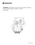
Models:
SA-Eliminator 48 S-100
SA-Eliminator 70 S-100
SA-Eliminator 90 S-100
S-100
Installation, Opeeration, and Maintenance Manual
MODEL:
SA-ELIMINATOR 48 S-100 Water Softener
o
o
Operating Temperature:
34 –120 F
Operating Pressure:
25–125 psi
Voltage:
110V 60 cycles
Rated Service Flow:
12.1 GPM @ 13 psi drop
Rated Softening Capacity:
31,200 @ 7.5; 41,900 @
(Grains / Pounds of Salt)
15.2; 47,600 @ 21.2
Max Flow Rate to Drain:
4.3 GPM
Amount of High Capacity Resin:
1.5 ft3
Rated Efficiency:
4,170 grains @ 7.5 lbs
MODEL:
SA-ELIMINATOR 70 S-100 Water Softener
o
o
Operating Temperature:
34 –120 F
Operating Pressure:
25–125 psi
Voltage:
110V 60 cycles
Rated Service Flow:
15.5 GPM @ 15 psi drop
Rated Softening Capacity:
48,000 @ 11.5; 64,400
(Grains / Pounds of Salt)
@ 23.3; 73,100 @ 32.5
Max Flow Rate to Drain:
4.6 GPM
Amount of High Capacity Resin:
2.3 ft3
Rated Efficiency:
4,170 grains @ 11.5 lbs
**Observe all state and local plumbing codes.
**The efficiency of the softener is valid only at the stated salt
dosage.
**This softener conforms to WQA S-100 for the specifically claimed
performance.
**Observe all state and local plumbing codes.
**The efficiency of the softener is valid only at the stated salt
dosage.
**This softener conforms to WQA S-100 for the specifically claimed
performance.
Manufactured By:
R&M Manufacturing
28 South 1550 West
Lindon UT 84042-1617
(801) 785-5557
Manufactured By:
R&M Manufacturing
28 South 1550 West
Lindon UT 84042-1617
(801) 785-5557
CAUTION: Do NOT use with water that
is microbiologically unsafe or of unknown
quality without adequate disinfection
before or after the system.
pn: LBL-ELIM-48-CERT
MODEL:
SA-ELIMINATOR 90 S-100 Water Softener
o
o
Operating Temperature:
34 –120 F
Operating Pressure:
25–125 psi
Voltage:
110V 60 cycles
Rated Service Flow:
18.0 GPM @ 15 psi drop
Rated Softening Capacity:
37,400 @ 8.8; 65,800
(Grains / Pounds of Salt)
@ 25.3; 74,700 @ 35.3
Max Flow Rate to Drain:
4.1 GPM
Amount of High Capacity Resin:
2.5 ft3
Rated Efficiency:
4,280 grains @ 8.8 lbs
**Observe all state and local plumbing codes.
**The efficiency of the softener is valid only at the stated salt
dosage.
**This softener conforms to WQA S-100 for the specifically claimed
performance.
Manufactured By:
R&M Manufacturing
28 South 1550 West
Lindon UT 84042-1617
(801) 785-5557
CAUTION: Do NOT use with water that
is microbiologically unsafe or of unknown
quality without adequate disinfection
before or after the system.
pn: LBL-ELIM-90-CERT
R&M Water Group
28 South 1550 West
Lindon, Utah 84042
P: (801) 785-5557
F: (801) 785-7823
© 2004 R&M Water Group All rights reserved.
ProFlow Eliminator is a registered trademark of R&M Water Group
pn: L-R-ProFlow-OM | rev: 02/04
CAUTION: Do NOT use with water that
is microbiologically unsafe or of unknown
quality without adequate disinfection
before or after the system.
pn: LBL-ELIM-70-CERT
Table of Contents
Installation. . . . . . . . . . . . . . . . . . . . . . . . . . . . . . . . . . . . . . . . . . . . . . . . . . . . . . . . . . . . . . . . . . . . . . . . 4
Location Selection
Water Line Connection
Drain Line Connection
Brine Line
Overflow Line Connection
Placing Conditioner into Operation. . . . . . . . . . . . . . . . . . . . . . . . . . . . . . . . . . . . . . . . . . . . . . . . . . 6
Electrical Connection
ProFlow 460i Series Control Seings . . . . . . . . . . . . . . . . . . . . . . . . . . . . . . . . . . . . . . . . . . . . . . . . 7
Programming
Time-of-Day Seing
Hardness Seing
Capacity Seing
Calendar Override Seing
Common Features. . . . . . . . . . . . . . . . . . . . . . . . . . . . . . . . . . . . . . . . . . . . . . . . . . . . . . . . . . . . . . . . . . 8
Salt Dial Adjustment
Guest Cycle
Manual Regeneration
Removing the Valve Assembly for Servicing . . . . . . . . . . . . . . . . . . . . . . . . . . . . . . . . . . . . . . . . 10
Controller Seing for Servicing . . . . . . . . . . . . . . . . . . . . . . . . . . . . . . . . . . . . . . . . . . . . . . . . . . . . 10
Preventive Maintenance . . . . . . . . . . . . . . . . . . . . . . . . . . . . . . . . . . . . . . . . . . . . . . . . . . . . . . . . . . . 11
Injector Screw and Injector
Water Meter
Specifications: Control Valve AUV-268-460i . . . . . . . . . . . . . . . . . . . . . . . . . . . . . . . . . . . . . . . . . 12
Pressure Graphs . . . . . . . . . . . . . . . . . . . . . . . . . . . . . . . . . . . . . . . . . . . . . . . . . . . . . . . . . . . . . . . . . . 13
Identification of Control Valving . . . . . . . . . . . . . . . . . . . . . . . . . . . . . . . . . . . . . . . . . . . . . . . . . . . 14
Valve Disc Principle of Operation . . . . . . . . . . . . . . . . . . . . . . . . . . . . . . . . . . . . . . . . . . . . . . . . . . 14
Flow Diagrams . . . . . . . . . . . . . . . . . . . . . . . . . . . . . . . . . . . . . . . . . . . . . . . . . . . . . . . . . . . . . . . . . . . 14
Replacement Parts AUV-1053832 . . . . . . . . . . . . . . . . . . . . . . . . . . . . . . . . . . . . . . . . . . . . . . . . . . . 16
Troubleshooting . . . . . . . . . . . . . . . . . . . . . . . . . . . . . . . . . . . . . . . . . . . . . . . . . . . . . . . . . . . . . . . . . . 19
Disinfection of Water Conditioners. . . . . . . . . . . . . . . . . . . . . . . . . . . . . . . . . . . . . . . . . . . . . . . . . 22
Sodium or Calcium Hypochlorite
ProFlow Eliminator | 3 |
Installation
All plumbing and electrical connections must conform to
local codes.
The most common bypass systems are the Autotrol Series 1265
bypass valve (1) and plumbed-in globe valves (2). Though both
are similar in function, the Autotrol Series 1265 bypass offers
simplicity and ease of operation.
Inspect unit carefully for carrier shortage or shipping
damage.
Not in Bypass
PA S S
4.
Do not install any unit closer to a water heater than a
total run of 10 feet (3 m) of piping between the outlet
of the conditioner and the inlet to the heater. Water
heaters can sometimes overheat to the extent they will
transmit heat back down the cold pipe into the unit
control valve.
Hot water can severely damage the conditioner. A 10foot (3-m) total pipe run, including bends, elbows, etc.,
is a reasonable distance to help prevent this possibility.
A positive way to prevent hot water flowing from heat
source to the conditioner, in the event of a negative
pressure situation, is to install a check valve in the so
water piping from the conditioner. If a check valve
is installed, make certain the water heating unit is
equipped with a properly rated temperature and
pressure safety relief valve. Also, be certain that
local codes are not violated.
5.
Do not locate unit where it or its connections
(including the drain and overflow lines) will ever be
subjected to room temperatures under 34oF (1oC) or
over 120oF (49oC).
6.
Do not install unit near acid or acid fumes.
7.
The use of resin cleaners in an unvented enclosure is
not recommended.
Water Conditioner
| 4 | ProFlow Eliminator
Water Conditioner
Figure 1: Autotrol Series 1265 bypass valve
Drain Line Connection
Note: Standard commercial practices are expressed
here. Local codes may require changes to the following
suggestions.
1.
Ideally located, the unit will be above and not
more than 20 feet (6.1 m) from the drain. For such
installations, using an appropriate adapter fiing,
connect 1/2-inch (1.3-cm) plastic tubing to the drain
line connection of the control valve.
2.
If the backwash flow rate exceeds 5 gpm
(22.7 Lpm) or if the unit is located more than 20 feet
(6.1 m) from drain, use 3/4-inch (1.9-cm) tubing for
runs up to 40 feet (12.2 m). Also, purchase appropriate
fiing to connect the 3/4-inch tubing to the 3/4-inch
NPT drain connection.
3.
If the unit is located where the drain line must be
elevated, you may elevate the line up to 6 feet
(1.8 m) providing the run does not exceed
15 feet (4.6 m) and water pressure at conditioner is
not less than 40 psi (2.76 bar). You may elevate an
additional 2 feet (61 cm) for each additional
10 psi (0.69 bar).
4.
Where the drain line is elevated but empties into a
drain below the level of the control valve, form a
7-inch (18-cm) loop at the far end of the line so that
Water Line Connection
The installation of a bypass valve system is recommended
to provide for occasions when the water conditioner must be
bypassed for hard water or for servicing.
BY
Since salt must be added periodically to the brine
tank, the location should be easily accessible.
Out
PA S S
3.
In
PA S S
If it is likely that supplementary water treatment
equipment will be required, make certain adequate
additional space is available.
Out
BY
2.
PA S S
The distance between the unit and a drain should be
as short as possible.
BY
Location Selection
1.
In Bypass
In
BY
This system is not intended to be used for treating water
that is microbiologically unsafe or of unknown quality
without adequate disinfection before or aer the system.
the boom of the loop is level with the drain line
connection. This will provide an adequate siphon trap.
5.
Where the drain empties into an overhead sewer line,
a sink-type trap must be used.
IMPORTANT: Never insert drain line into a drain, sewer
line or trap. Always allow an air gap between the drain
line and the wastewater to prevent the possibility of
sewage being back-siphoned into the conditioner.
Note: Standard commercial practices have been
expressed here. Local codes may require changes to these
suggestions.
Right Way
1” Air Gap
Overflow Line Connection
In the absence of a safety overflow and in the event of a
malfunction, the BRINE TANK OVERFLOW will direct
“overflow” to the drain instead of spilling on the floor
where it could cause considerable damage. This fiing
should be on the side of the cabinet or brine tank.
To connect overflow, locate hole on side of brine tank.
Insert overflow fiing (not supplied) into tank and tighten
with plastic thumb nut and gasket as shown (4). Aach
length of 1/2-inch (1.3-cm) I.D. tubing (not supplied) to
fiing and run to drain. Do not elevate overflow line
higher than 3 inches (7.6 cm) below boom of overflow
fiing. Do not tie into drain line of control unit. Overflow
line must be a direct, separate line from overflow fiing
to drain, sewer or tub. Allow an air gap as per drain line
instructions (2).
Overflow
Fitting Installed
Brine Tank
Figure 2: Drain line with air gap
Brine Line Connection
It will be necessary to install the brine line to the brine
fiing on the valve (3/8-inch NPT).
Connect 1/2-inch (1.3 cm)
Tubing or Hose and Run to Drain.
Figure 3: Overflow fiing
Be sure all fiings and connections are tight.
Drain Line
Incoming
To House
Overflow
Caution! Do NOT connect coverflow and
drainline. Brine tank overflow will occur.
1" Air Gap
Figure 4: Eliminator drain and overflow layout
ProFlow Eliminator | 5 |
Placing Conditioner into
Operation
Aer all previous steps have been completed, the unit
is ready to be placed into operation. Follow these steps
carefully.
1.
Remove control valve cover by first releasing the
plastic clip from the back of the cover. Pull back of
cover slightly outward and li up.
Note: The following steps will require turning the
indicator knob ( and ) to various positions. Manually
rotate the camsha COUNTERCLOCKWISE only
until indicator knob points to desired position. (See
manual regeneration sections for each control’s
manual operation.)
2.
Rotate indicator knob COUNTERCLOCKWISE until
it points directly to the word BACKWASH.
3.
Fill media tank with water.
a. With water supply off, place the bypass valve(s)
into the “not in bypass” position.
b. Open water supply valve very slowly to
approximately the 1/4 open position.
IMPORTANT: If opened too rapidly or too far, media
may be lost. In the 1/4 open position, you should hear air
escaping slowly from the drain line.
c. When all of the air has been purged from the tank
(water begins to flow steadily from the drain),
open the main supply valve all the way.
d. Allow water to run to drain until clear.
e. Turn off water supply and let the unit stand for
about five minutes. This will allow all trapped air
to escape from the tank.
4,
Add water to brine tank (initial fill).
With a bucket or hose, add approximately
4 gallons (15 liters) of water to brine tank. If the tank
has a salt platform above the boom of the tank, add
water until the level is approximately 1 inch (25 mm)
above the platform.
| 6 | ProFlow Eliminator
5
Place the conditioner into operation.
a. With the water supply valve completely
open, carefully advance the indicator knob
COUNTERCLOCKWISE to the center of the
BRINE REFILL position. Hold at this position
until water starts to flow through the brine line
into the brine tank. Do not run for more than one
or two minutes.
b. Advance the indicator knob
COUNTERCLOCKWISE until it points to the
center of the BRINE/SLOW RINSE position.
c. With the conditioner in this position, check to
see if water is being drawn from the brine tank.
The water level in the brine tank will recede
very slowly. Observe water level for at least three
minutes. If the water level does not recede, or if it
goes up, reference the Troubleshooting section.
d. Advance the indicator knob
COUNTERCLOCKWISE to the SERVICE
position and run water from a nearby faucet until
the water is clear and so.
Electrical Connection
100 VAC, 115 VAC, and 230 VAC units: Remove twist tie
from the power cord and extend cord to its full length.
Make sure power source matches the rating printed on
the control. Be certain a wall switch does not control the
outlet.
12 VAC: Connect the plug of the transformer (supplied)
secondary cable to the mating socket at the rear or boom
of the timer housing. Be certain the transformer is secure
and is plugged into a power source of correct voltage that
is not controlled by a wall switch.
Ion Exchange
Cation resin is used to create the ion-exchange process
wherein dissolved minerals are removed and replaced
with sodium ions.
Pro Flow 460i Series
Control Settings
ProFlow 460i Control
Water-Flow Indicator
Hour Time Display
PM Indicator
Access Door
Raised Tab
Jumper
Spare Jumper
Indicator Knob
Time-Set Button
Timer Locking Pin
Transformer Plug Receptable
Programming
Plug the wall-mount transformer into a functioning
electrical outlet that is not controlled by a switch. Plug the
transformer into the transformer plug receptacle on the
control.
Open the access door by pushing the raised tab on the
door toward the le while pulling the tab out (5).
Time-of-Day Setting
With the jumper on the set of pins next to the word TIME
(6), set the time of day to the closest hour by pressing the
black TIME SET buon. PM hours are indicated by a light
next to the leers PM on the display window.
Note: The use of a small needle-nose pliers will aid in
moving the jumper.
Note: The unit is factory set to regenerate at 2:00 a.m. If
you prefer to have the unit regenerate at an earlier or later
time, simply set the current time of day accordingly (e.g.,
to have the unit regenerate at
4:00 a.m.—two hours later—set the clock two hours earlier
than the actual time of day).
Note: The Timer Locking Pin should always be horizontal
(5) during operation.
ProFlow Eliminator | 7 |
Hardness Setting
Move the jumper to the set of pins next to the word
HARDNESS (8). Press the black TIME SET buon until the
hardness of the incoming water supply is displayed. The
hardness range is from 1 to 99 grains per gallon.
To change water hardness stated in parts per million
(PPM) to grains per gallon (GPG) use this formula:
ppm
17.1
4.
Depress the black TIME SET buon. The numbers will
roll from “0” to “15.” Release the switch at the desired
number of days for the calendar override. For example,
releasing the switch at “10” would program a 10-day
calendar override.
5.
Disconnect power.
6.
Place jumper back on TIME and reconnect power.
7.
The calendar override program is maintained during
power outages by the NOVRAM circuitry.
8.
To remove the calendar override, follow the same
steps above and program back to “0.”
= gpg
Figure 6
Figure 8
Figure 9
Capacity Setting
Move the jumper to the set of pins next to the word
CAPACITY (9). Press the black TIME SET buon until the
correct capacity value is displayed. The capacity range is 1
to 99 kilograins. Refer to the Suggested Salt Dial Seings
table (8).
Return the jumper to the top set of pins next to the word
TIME and replace the access door. The jumper must
NOT be le on any pins other than the top pair next to
the word TIME. Otherwise, the unit may show a blank
display.
Note: A spare jumper is located on the boom set of pins.
In the event that the hardness or capacity seing must be
changed, simply follow the appropriate steps described
above.
Calendar Override Setting
1.
Disconnect power.
2.
Place jumper on Pin A and reconnect power.
3.
Move jumper to Pin B. A zero will appear, indicating
zero days of calendar override. All controllers are
preprogrammed in this manner at the manufacturer.
Note: System comes pre-programmed with default
hardness, capacity and corresponding salt seings. Refer
to table 1 for default seings.
| 8 | ProFlow Eliminator
Common Features
Salt Dial Adjustment
These models may be adjusted to produce maximum to
minimum conditioning capacities by seing the salt dial,
which controls the amount of salt used per regeneration.
When desired, the minimum seing may be used on
installations if the frequency of regeneration is increased
to compensate for lower regenerated conditioning
capacity. The installing dealer will set the unit for proper
salt usage. Further adjustments are needed only if the
hardness of the water supply changes or if water use
changes dramatically. Capacity will need to be adjusted
accordingly.
To adjust salt dosage, insert a small screwdriver into the
white indicator knob and move pointer to proper salt
seing (Figure 10).
Note: To convert the salt seings from English to metric,
divide by 2.2 (e.g., 12 pounds ³ 2.2 = 5.5 kg of salt).
Indicator Knob
Figure 9: Indicator Knob
Model
48
70
90
Capacity
Default
Seing Salt Seing
31,200 gr
48,000 gr
37,400 gr
Model
7.5 lbs
48
70
11.5 lbs
90
8.8 lbs
Table 1: Default salt seing, by model
Max Flow Pressure Drop @
Rate
Max Flow
12.1 gpm
15.5 gpm
18.0 gpm
Exchange
Media
Max Flow to Drain
(Regeneration)
13.0 psi
1.5 3
2.5 gpm
15.0 psi
2.3 3
3.5 gpm
2.5 3
4.0 gpm
15.0 psi
Table 2: Flow rates and pressure loss
Efficiency Ratings
Model
Tot. Gr.
Recovr’d
Gr.
Recov’rd
p/ Salt lb
HighEff. Salt
Seing
Tot. Gr.
Recovr’d
Gr.
Recovr’d
p/ Salt lb
MidEff. Salt
Seing
Tot. Gr.
Recovr’d
Gr.
Recovr’d
p/ Salt lb
LowEff. Salt
Seing
48
31,200 gr
4,160.0 gr
7.5 lbs
41,900 gr
2,756.6 gr
15.2 lbs
47,600 gr
2,245.3 gr
21.2 lbs
70
48,000 gr
4,170.0 gr
11.5 lbs
64,400 gr
2,763.9 gr
23.3 lbs
73,100 gr
2,249.2 gr
32.5 lbs*
90
37,400 gr
4,200.0 gr
8.8 lbs
65,800 gr
2,600.8 gr
25.3 lbs
74,700 gr
2,116.1 gr
35.3 lbs*
Table 3: Efficiency salt seings
* Extra salt cam: divide the suggested seing by 2 to accomplish salt seing.
Note: Use any good grade rock salt (NaCl) to obtain rated capacities.
The amount of salt placed in the brine tank has nothing to
do with the amount of salt used during the regeneration
cycle. Water will dissolve and absorb salt only until
it becomes saturated. A given amount of brine (saltsaturated water) contains a specific amount of salt. The
salt dial controls the amount of brine used during the
regeneration cycle (e.g., when set at
15 pounds (6.8 kg) the amount of brine the conditioner
will use for each regeneration will contain 15 pounds
(6.8 kg) of salt, etc.)
Never let the amount of salt in the brine tank be lower
than the normal liquid level. Do not overload the brine
tank with salt.
Guest Cycle
When abnormally high water usage exhausts your
water conditioner’s capacity ahead of schedule, an extra
regeneration can be achieved. Depress the indicator
knob on the 440i (5) with a wide-blade screwdriver and
turn COUNTERCLOCKWISE to START to initiate a
regeneration. For the 460i, simply depress the indicator
knob (5). It will take a few minutes for regeneration to
start. A normal regeneration will take approximately two
hours.
Manual Regeneration
Electricity is used only to run the control and to
rotate the camsha. All other functions are operated
by water pressure. Therefore, in the event of a power
outage, all the regeneration positions may be dialed
manually by depressing the indicator knob and turning
COUNTERCLOCKWISE ( and ). The following cycle
times should be used for proper regeneration:
BACKWASH—14 minutes
BRINE/SLOW RINSE—52 minutes
FAST RINSE/REFILL—10 minutes
PURGE—6 minutes
Do not exceed 10 minutes for the FAST RINSE/REFILL
cycle as this will cause excessive salt usage during the next
regeneration and possibly a salt residue in the soened
water.
Soener conforms to WQA S-100 for the
specific performance claims as verified and
substantiated by test data.
ProFlow Eliminator | 9 |
Removing the Valve
Assembly for Servicing
1.
Unplug the power cord.
2.
Shut off water supply or put bypass valve(s) into
bypass position.
3.
Remove cover and with screwdriver, relieve tank
pressure by pushing open valve No. 7 (rear flapper)
on control as shown (Figure 11).
4.
When used with a globe valve bypass, loosen and
detach the inlet, outlet, brine and drain lines from the
valve. If using the bypass, loosen and remove valve
from bypass as well as loosening and removing the
brine and drain lines.
5.
Unscrew valve (counterclockwise) and remove valve
from tank.
6.
To replace the control valve, reverse the above
procedure.
Controller for Servicing
1.
Unplug the power cord.
2.
Remove cover.
3.
Align the indicator arrow on the rear of the camsha
with the top of the rear hoop of the top plate (Figure
12).
Indicator Arrow
Figure 12: Top-down view of valve
4.
Remove the camsha by carefully pushing the
securing tab, located at the rear of the camsha, away
from the camsha until the tab disengages from the
camsha. Push the back of the camsha down and out
to the inlet side of the valve (Figure 13).
Figure 11: Valve assembly
Figure 13: Removing the camsha
| 10 | ProFlow Eliminator
5.
Disengage the front of the camsha from the output
gear of the control.
6.
Remove the timer locking pin and li the control
straight up and off of the valve.
7.
To reinstall the camsha and control, reverse the
above procedures.
Preventive Maintenance
Injector Screen and Injector
Inspect and clean brine tank and screen filter on end of
brine pickup tube once a year or when sediment appears
in the boom of the brine tank.
Clean injector screen and injector once a year:
Water Meter Maintenance
Note: A water meter is used only with the 460i control.
If you are using the 440i control, this section does not
pertain to your conditioner.
The metering device used with the 460i demand control
may require simple maintenance. In rare instances,
the turbine wheel of the water meter can collect small
particles of oxidized iron, eventually preventing the wheel
from turning.
1.
Unplug the wall-mount transformer.
2.
Shut off water supply or put bypass valve(s) into
bypass position.
1.
Shut off the water supply or put the bypass valve(s)
into the bypass position.
3.
Relieve system pressure by opening valve No. 7
(at rear) with a screwdriver (Figure 11).
2.
4.
Using a screwdriver, remove injector screen and
injector cap (Figure 14).
Relieve pressure by opening the Backwash Drain
Valve (the seventh back from the control) with a
screwdriver (Figure 11).
3.
5.
Clean screen using a fine brush. Flush until clean.
Loosen and remove the pipe/tube adapters or 1265
bypass from the inlet and outlet of the valve body.
6.
Using a needle-nose pliers, pull injector straight out.
4.
7.
Flush water into the injector screen recess of the valve
body to flush debris out through the injector recess.
Using a needle-nose pliers, remove the turbine from
the outlet housing. Grasp one of the four vanes of the
outer gland and pull straight out to remove turbine
assembly from the outlet of the valve (Figure 14).
8.
Clean and flush the injector.
5.
9.
Lubricate the O-rings on the injector, injector cap and
injector screen with silicone lubricant only!
Carefully remove the turbine wheel from the housing.
Use a toothbrush to lightly scrub the iron off the
magnet. Iron buildup on the surfaces can be removed
by soaking the wheel in a mild sodium hydrosulfite
(such as RoVer*) solution for a few minutes. Flush
thoroughly with water.
6.
Carefully reinstall the turbine wheel into the turbine
cage housing. Make sure that the sha of the wheel
seats into the bearing of the cage. Reassemble the
turbine cage and check that the wheel rotates freely.
7.
Reinstall the turbine cage into the outlet of the valve.
8.
Reinstall the pipe/tube adapters or 1265 bypass to the
inlet and outlet of the valve.
9.
Turn on the water supply or put the bypass valve(s)
into the service position and purge the air out of the
system.
10. Reinstall the injector, injector cap and injector screen.
IMPORTANT: Do not overtighten the plastic cap. Seat
the cap lightly into position. Overtightening may cause
breakage of the plastic cap that may not be immediately
evident.
11. Plug the wall-mount transformer into outlet; reset
clock if necessary.
12. Slowly open water supply valve or return bypass
valve(s) to the “service” position.
To check for proper meter operation, open a downstream
faucet and observe the water flow indication on the
control display.
*RoVer is a trademark of Hach Chemical Company.
Figure 14: Removing injector screen and injector cap
ProFlow Eliminator | 11 |
Specifications: Control Valve AUV - 268-460i
Hydrostatic Test Pressure. . . . . . . . . . . . . . . . . . . . . . . . . . . . . . . . . . . . . . . . . . . . . . . . . . . . . . . . . . . . . . . . . . . . . . . . 300 psi (20.69 bar)
Working Pressure . . . . . . . . . . . . . . . . . . . . . . . . . . . . . . . . . . . . . . . . . . . . . . . . . . . . . . . . . . . . . . . . . . . . . . 20-125 psi (1.38 - 8.62 bar)
Standard Electrical Rating . . . . . . . . . . . . . . . . . . . . . . . . . . . . . . . . . . . . . . . . . . . . . . . . . . . . . . . . . . . . . . . . . . . . . . . . . . . . . 115V 60 Hz
Optional Electrical Rating . . . . . . . . . . . . . . . . . . . . . . . . . . . . . . . . . . . . . 115V 50 Hz, 230V 50 Hz, 200V 60 Hz, 24V 60 Hz, 24V 50 Hz,
100V 60 Hz, 100V 50 Hz, 12V 50 Hz/transformer, 12V 60 Hz/transformer
Electrical Cord (standard rating) . . . . . . . . . . . . . . . . . . . . . . . . . . . . . . . . . . . . . . . . . . . . . . . . . . . . . . . 60 inch (1.5 m) 3-wire with plug
Pressure Tank Thread. . . . . . . . . . . . . . . . . . . . . . . . . . . . . . . . . . . . . . . . . . . . . . . . . . . . . . . . . . . . . . . . . . . . . . . . . . . . 2 1/2 inch-8 male
Riser Pipe Diameter Required . . . . . . . . . . . . . . . . . . . . . . . . . . . . . . . . . . . . . . . . . . . . . . . . . . . . . . . . . . . . . . . . . 1.3 inch OD (26.7 mm)
Riser Pipe Length . . . . . . . . . . . . . . . . . . . . . . . . . . . . . . . . . . . . . . . . . 1-1/8 ±1/8 inches (31.8 mm) higher than the top of mineral tank
Standard Connection . . . . . . . . . . . . . . . . . . . . . . . . . . . . . . . . . . . . . . . . . . . . . . . . . . . . . . . . . 1-inch (25.4-mm) copper tube adapters
Optional Connections . . . . . . . . . . . . . . . . . . . . . . . . . . . . . . . . . . . . . . . . . . . . . . . 3/4-inch, 22-mm, and 28-mm copper tube adapters
1 1/4-inch copper
3/4-inch, 1-inch, 25-mm CPVC tube adapters
Brine Line Connection . . . . . . . . . . . . . . . . . . . . . . . . . . . . . . . . . . . . . . . . . . . . . . . . . . . . . . . . . . . . . . . . . . . . . . . . . . 3/8-inch NPT male
Drain Line Connection. . . . . . . . . . . . . . . . . . . . . . . . . . . . . . . . . . . . . . . . . . . . . . . . . . . . . . . . . . . . . . . . . . . . . . . . . . 3/4-inch NPT male
Optional Bypass Valve . . . . . . . . . . . . . . . . . . . . . . . . . . . . . . . . . . . . . . . . . . . . . . Rotating handles, full 1-inch porting, reinforced Noryl
Control Module, Tank Adapter . . . . . . . . . . . . . . . . . . . . . . . . . . . . . . . . . . . . . . . . . . . . . . . . . . . . . . . . . . . . . . . . . . . . Reinforced Noryl
Rubber Goods . . . . . . . . . . . . . . . . . . . . . . . . . . . . . . . . . . . . . . . . . . . . . . . . . . . . . . . . . . . . . . . . . . Compounded for cold water service
Program Clock (Timer). . . . . . . . . . . . . . . . . . . . . . . . . . . . . . . . . . . . . . . . . . . . . . . . . . . . . . . . . . . . . . . . . . . . . 460i: Available in English
Brine Refill Control . . . . . . . . . . . . . . . . . . . . . . . . . . . . . . . . . . . . 1 to 10 lbs (0.45 to 4.5 kg) of salt or 3 to 19 lbs (1.4 to 8.6 kg) of salt
Injector Size “A” White . . . . . . . . . . . . . . . . . . . . . . . . . . . . . . Nozzle 042-inch (1.1-mm) diameter, Throat .089-inch (2.3-mm) diameter
Injector Size “B” Blue. . . . . . . . . . . . . . . . . . . . . . . . . . . . . . . Nozzle .052-inch (1.3-mm) diameter, Throat .099-inch (2.5-mm) diameter
Injector Size “C” Red . . . . . . . . . . . . . . . . . . . . . . . . . . . . . . . Nozzle .059-inch (1.5-mm) diameter, Throat .099-inch (2.5-mm) diameter
Injector Size “D” Green . . . . . . . . . . . . . . . . . . . . . . . . . . . . . . Nozzle .071-inch (1.8-mm) diameter, Throat .147-inch (3.7-mm) diameter
Internal Backwash Controllers. . . . . . . . . . . . . . . . . . . . . . . . . . . . . . . 7- through 14-inch (17.8- though 35.6-cm) diameter media tanks
All sizes to flow 4.5 gpm/sq ft (183 L/m/m2) of bed area.
For tank sizes above 14 inches in diameter, use an external flow control.
| 12 | ProFlow Eliminator
Specifications: Control Valve AUV - 268-460i
Injector #1031363
Injector #1031364
"A" in a 268 Valve
"B" in a 268 Valve
1.00
0.30
0.20
Total
1.25
0.25
0.75
0.20
Rinse
0.05
0.00
0.50
Brine Draw
0.15
0.75
GPM
0.10
M3/hr
Rinse
GPM
M3/hr
0.15
Total
1.00
0.10
0.50
0.05
0.25
0.00
0.00
Brine Draw
0.25
0.00
20
40
60
400 600
PSI
80
100
120
20
800 1000 1200 1400 1600 1800
bar
40
400 600
1.25
0.20
0.10
0.05
M3/hr
Rinse
GPM
M3/hr
0.25
Total
1.00
0.75
0.05
0.25
0.00
0.15
0.10
Brine Draw
0.50
0.00
0.00
20
40
60
400 600
PSI
80
100
120
800 1000 1200 1400 1600 1800
bar
100
120
800 1000 1200 1400 1600 1800
bar
2.25
2.00
1.75
1.50
1.25
1.00
0.75
0.50
0.25
0.00
Total
Rinse
GPM
0.30
1.75
0.15
80
"D" in a 268 Valve
"C" in a 268 Valve
1.50
PSI
Injector #1030272
Injector #1031365
0.20
60
Brine Draw
20
40
400 600
60
PSI
80
100
120
800 1000 1200 1400 1600 1800
bar
Model
48
70
90
Backwash Number
10
12
12
Flow* (gpm)
2.5
3.5
3.5
Flow* (lpm)
9.5
13.2
* Approximate flow rates at 60 psi (4.14 bar).
13.2
ProFlow Eliminator | 13 |
Identification of
Control Valving
Valve Disc
Principle of Operation
Backwash Drain Valves (7)
Refill Valve (5)
Cam
Inlet Valve (3)
Valve Disc
Brine Valve (1)
Rinse Drain Valve (6)
Outlet Valve (4)
Bypass Valve (2)
Valve Seat
Valve Disc Closed
Flow Diagrams
Service Position
Valve Position
1
Closed
2
Closed
3
Open
4
Open
5
Closed
6
Closed
7
Closed
| 14 | ProFlow Eliminator
Backwash Position
Valve Position
1
Closed
2
Open
3
Closed
4
Open
5
Closed
6
Closed
7
Open
Valve Disc Open
Brining / Slow-Rinse Position
Valve Position
1
Closed
2
Closed
3
Open
4
Open
5
Open
6
Closed
7
Closed
Purge Position
Valve Position
1
Closed
2
Open
3
Open
4
Closed
5
Closed
6
Open
7
Closed
Brine Refine Position
Valve Position
1
Closed
2
Closed
3
Open
4
Open
5
Open
6
Closed
7
Closed
ProFlow Eliminator | 15 |
Replacement Parts AUV - 1053832
ProFlow: High-Flow Eliminator Series
6
19
14
3
8
12
Parts List
Code
1
Part #
Description
AUV-1053832
Control Valve (Complete)
Valve Assembly, w/o Flow Controls
(460i)
2a
Qty
Code
1
8
Camshaft: (all models)
1
1
2b
AVP-1035627
Extra Salt Cam (for model 90 only)
3
AVP-1031391
Timer Locking Pin
1
Drain Control Assembly
1
4
5
AVP-1000212
No. 10 (2.5 gpm; 9.5 Lpm)
AVP-1000213
No. 12 (3.5 gpm; 13.2 Lpm)
AVP-1030502
6
Part #
Ball, Flow Control
2
1
1 to 10 Pounds Salt
AVP-1034263
3 to 19 Pounds Salt
9
AVP-1002449
Drain Fitting Elbow (3/4” hose
barbed)
10
AVP-1000226
Screen/Cap Assembly
1
11
AVP-1010429
O-Ring
1
12
AVP-1035622
Tank Ring
1
14
AVP-1033444
AVP-1001580
Meter
1
Spring, Flapper Valve
1
“A” Injector - White
15
AVP-1032971
“B” Injector - Blue
*
AVP-1032972
“C” Injector - Red
AVP-1041174
Standard
AVP-1030272
“D” Injector - Green
AVP-1041175
Severe Service
Injector Cap Assembly
AVP-1000217
“A” Cap
AVP-1000218
“B” Cap
AVP-1000219
“C” Cap
AVP-1030303
“D” Cap
| 16 | ProFlow Eliminator
1
1
Plumbing Adapter Kits:
Turbine Assembly (460i only)
AVP-1032970
7
Qty
1
AVP-1034261
13
Injector Assembly:
Description
Brine Refill Control (460i)
Valve Disc Kit
AVP-1000062 I-Lid Cover
*
* Not Shown
** Soft water refill is not available with the extra salt cam.
1
Replacement Parts: Distributor Assembly
All Models (48, 70, and 90)
2
1
DST-2001: High-Flow
Upper Distributor
4,5
3
10
9
7
13
14
11
6
15
12
8
Code #6: DST-1021-E: High-Flow Distributor
SA-Eliminator 48, 70, and 90 (S-100)
Code #4: Eliminator
Cap Number
JKT-1220
Code
JKT-1165
JKT-1095
Eliminator 48
JKT-1115
Eliminator 70
JKT-1180
Eliminator 90
JKT-1233
Code #5: Eliminator Jacket Numbers
Part #
Description
48
Qty
70
Qty
90
Qty
1
AUV-1053832
268/460i Meter
1
1
1
2
AVP-1000062
I-Lid Cover, 255, 268
1
1
1
3
DST-2000
Top Dist. Bajonet
1
1
1
4
See options (left)
5
See options (left)
6
See drawing (upper left)
7
MDA-1000
78 lbs
119 lbs
130 lbs
8
BTC-1210
BT 1840 Blk
1
1
1
9
BTC-1000
2 PC Overflow Set
1
1
1
10
BTC-1114
Brine Well 4x36 Slot
1
1
1
11
BTC-1306
Cap 4"
2
2
2
HCR Cation Resin
12
BTC-1037
Air Check, 3/8"
1
1
1
13
BTC-1033
474 Brine Valve 3/8"
1
1
1
14
BTC-1036
474 Float
1
1
1
15
MTK-SP-1044
Tank: 10"x44"
1
—
—
MTK-SP-1248
Tank: 12"x48"
—
1
—
MTK-SP-1447
Tank: 14"x47"
—
—
1
*Note: Drawing above is based on model 48. Larger models (70 and
90) increase case size respectively as seen at left.
ProFlow Eliminator | 17 |
460i Control
BP-A-1040930
B Y PA S S
B Y PA S S
Code #2
Code #3: Bypass
Code
Part #
2
Description
Qty
Bypass Kit
460i Control
1
BP-A-1001606
3/4" Copper Tail Kit
3
AVP-1040930
1265 Bypass (see table at right)
1
BP-A-1001670
1" Copper Tail Kit
*
AVP-1000811
Transformer (460i):
1
BP-A-1001210
1 1/4" Copper Tail Kit
*
AVP-1000907
Transformer Extension Cord
15 feet (4.6 m)
1
BP-A-1001613
3/4" CPVC Tail Kit
BP-A-1001614
1" CPVC Tail Kit
Y-Splitter (run 2 units from 1
transformer)
1
*
AVP-1034264
*Not shown.
| 18 | ProFlow Eliminator
Troubleshooting
The technology upon which the control valve is based is
well established and proven in service over many years.
However, should a problem or question arise regarding
the operation of the system, the control can very easily be
serviced. For parts mentioned, refer to exploded views in
the Replacement Parts section of this manual.
IMPORTANT: Service procedures that require the water
pressure to be removed from the system are marked with
a “§ ” aer the possible cause. To remove water pressure
from the system, put the bypass valve or three-valve
bypass into the bypass position and open the backwash
drain valve (the seventh valve back from the control) with
a screwdriver. Restore system water pressure when the
service work is completed.
The problems outlined below are the most common
occurances of problems. If you are unable to solve your
problem with this manual, contact the manufacturer.
Valve Troubleshooting
Problem
Possible Cause
Solution
Control will not draw brine.
Low water pressure.
Set pump to maintain 30 psi at conditioner.
Restricted drain line.
Remove restriction.
Injector plugged§
Lean injector and screen.
Injector defective§
Replace injector.
Valve (2 and/or 4) not closed.
Remove foreign matter from disc and check
disc for closing by pushing in on stem. Replace
if needed.
Brine valve (1) being held open.
Manually operate valve stem to flush away
obstruction.
Uncontrolled brine refill flow rate§
Remove variable salt controller to clean.
Valve (3 or 4) not closed during brine draw
causing refill.
Flush out foreign matter by holding disc open
and manually operating valve stem.
Air leak in brine line.
Check all connections in brine line for leaks.
Refer to instructions.
Inaccurate setting.
Correct setting.
Foreign matter in controller causing incorrect
flow rates§
Remove variable salt controller and flush out
foreign matter. Manually position control to
brine draw to clean controller (after so doing,
position control to “purge” to remove brine
from tank).
Defective controller.
Replace controller.
Intermittent or irregular brine draw.
Low water pressure.
Set pump to maintain 30 psi at conditioner.
Defective injector§
Replace both injector and injector cap.
No conditioned water after regeneration.
Unit did not regenerate.
Check for power.
Brine tank overflow.
System using more or less salt than salt control
is set for.
No salt in brine tank.
Add salt.
Plugged injector§
Clean injector. Flush with water.
Control backwashes at excessively low or high
rate.
Incorrect backwash controller used.
Replace with correct size controller.
Foreign matter affecting controller operation§
Remove controller and ball. Flush with water.
Flowing or dripping water at drain or brine line
after regeneration.
Drain valve (5 or 6) or brine valve (1) held open
by foreign matter or particle.
Manually operate valve stem to flush away
obstruction.
Hard water leakage during service.
Valve stem return spring on top plate weak.
Replace spring.
Improper regeneration.
Repeat regeneration making certain that the
correct salt dosage is set.
Leaking of bypass valve§
Replace O-ring.
O-ring around riser tube
damaged§
Replace O-ring.
§ This procedure requires removal of water pressure from the system.
ProFlow Eliminator | 19 |
460i Control Troubleshooting
Problem
Possible Cause
Solution
Clock does not display time of day.
Transformer cord unplugged.
Connect power.
No electric power at outlet.
Repair outlet or use working outlet.
Clock does not display correct time of day.
Defective transformer.
Replace transformer.
Defective circuit board.
Replace timer.
Outlet operated by switch.
Use outlet not controlled by switch.
Incorrect voltage or frequency (Hz).
Replace timer with one of correct voltage and
frequency (Hz).
Power outages.
Reset clock.
Time display continues to advance.
Defective time set switch.
Replace timer.
Time display shows something other than time
of day.
Electrical interference.
Disconnect power to unit. Restore power and
reset time of day
Defective circuit board.
Replace timer.
No water flow display when water is flowing.
Control regenerates at wrong time of day.
Timer stalled in regeneration cycle.
Continuous regeneration. Camshaft does not
stop at the end of regeneration.
Bypass valve in bypass.
Shift bypass valve to not-in-bypass position.
Meter probe disconnected or not fully
connected to meter housing.
Fully insert probe into meter housing.
Restricted meter turbine rotation due to
foreign matter in meter.
Remove meter housing, free up turbine and
flush with clean water. Do not disassemble
turbine from meter housing. Turbine should
spin freely. If not, replace meter§
Defective meter probe.
Replace timer.
Defective circuit board.
Replace timer.
Power outages.
Reset clock to correct time of day.
Clock set incorrectly.
Reset clock to correct time of day.
Motor dead.
Replace timer.
Motor runs backward.
Replace timer.
No electric power at outlet.
Repair outlet or use working outlet.
Broken gear.
Replace timer.
Defective switch.
Replace timer.
Air leak in brine connections.
Check all junction points and make appropriate
corrections.
Binding of camshaft.
Remove foreign object obstruction from valve
discs or camshaft.
Water pressure greater than 125 psi during
regeneration.
Install pressure regulator§
Defective circuit board.
Replace timer.
Broken switch activator on gear.
Defective switch.
§ This procedure requires removal of water pressure from the system.
| 20 | ProFlow Eliminator
Replace timer.
Replace timer.
460i Control Troubleshooting (con't)
Problem
Possible Cause
Solution
Control will not regenerate automatically or
when button is pressed.
Electric cord unplugged.
Connect power.
No electric power at outlet.
Repair outlet or use working outlet.
Defective motor.
Replace timer.
Broken gear.
Replace timer.
Control will not regenerate automatically but
will regenerate when button is pressed.
Run out of soft water between regenerations.
Binding in gear train.
Replace timer.
Defective switch.
Replace timer.
If water flow display is not operative, refer to
Item 5
Same as Item 5.
Defective circuit board.
Replace timer.
Incorrect hardness and capacity settings.
Set to correct values. See Programming
section.
Improper regeneration.
Repeat regeneration, making certain that
correct salt dosage is used.
Fouled softener resin.
Use resin cleaner. See Note 1.
Incorrect salt setting.
Set salt control to proper level. See Salt Setting
chart.
Incorrect harness or capacity settings.
Set to correct values. See Programming
section.
Water hardness has increased.
Set hardness to new value. See Programming
section.
Restricted meter turbine rotation due to
foreign material in meter housing.
Remove meter housing, free us turbine and
flush with clean water. DO NOT DISASSEMBLE
TURBINE FROM METER HOUSING. Turbine
should spin freely, if not, replace meter§
Excessive water usage below 1/5 gallon per
minute.
§ This procedure requires removal of water pressure from the system.
Repair leaky plumbing and/or fixtures§
Note: 1: Use of resin cleaners in an unvented enclosure is not recommended.
ProFlow Eliminator | 21 |
Disinfection of Water
Conditioners
1. Dosage
a. Polystyrene resin: 1.2 fluid ounces per cubic foot.
b. Non-resinous exchangers: 0.8 fluid ounce per cubic
foot.
The materials of construction of the modern water
conditioner will not support bacterial growth, nor will
these materials contaminate a water supply. However,
the normal conditions existing during shipping, storage
and installation indicate the advisability of disinfecting
a conditioner aer installation, before the conditioner is
used to treat potable water. In addition, during normal
use, a conditioner may become fouled with organic maer
or in some cases with bacteria from the water supply.
2.
Thus every conditioner should be disinfected aer
installation, some will require periodic disinfection
during their normal life, and in a few cases disinfection
with every regeneration would be recommended.
Depending upon the conditions of use, the style
of conditioner, the type of ion exchanger, and the
disinfectant available, a choice can be made among the
following methods.
Calcium Hypochlorite
Calcium hypochlorite, 70% available chlorine, is available
in several forms including tablets and granules. These solid
materials may be used directly without dissolving before
use.
1.
Dosage
a. Two grains (approximately 0.1 ounce) per cubic
foot.
2.
Brine tank conditioners
a. Backwash the conditioner and add the required
amount of hypochlorite to the brine well of the
brine tank. (The brine tank should have water in it
to permit the chlorine solution to be carried into the
conditioner.)
b. Proceed with the normal regeneration. This will
flush and condition the unit for use.
Application
These materials are satisfactory for use with polystyrene
resins, synthetic gel zeolite, greensand and bentonites.
5.25% Sodium Hypochlorite
These solutions are available under trade names such
as Clorox Bleach*. If stronger solutions are used, such as
those sold for commercial laundries, adjust the dosage
accordingly.
Brine tank conditioners
a. Backwash the conditioner and add the required
amount of hypochlorite solution to the brine well of
the brine tank. (The brine tank should have water
in it to permit the solution to be carried into the
conditioner.)
b. Proceed with the normal regeneration. This will
flush and condition the unit for use.
*Clorox is a registered trademark of The Clorox Company.
Caution: Do NOT install on water that is microbiologically unsafe,
or of unknown quality without adequate disinfection before or aer the system.
| 22 | ProFlow Eliminator
Manufacturer’s Warranty
R&M Water Group
A Division of Water Technologies Inc.
To the original purchaser, the valve body, mineral container, cation resin, and salt tank
carry an unconditional, non-prorated lifetime guarantee, which may be replaced F.O.B.
R&M Service Center.
This water conditioner, manufactured by R&M Water Group, is unconditionally
guaranteed as to workmanship and materials at the original installation site for a
period of five years from the date of original purchase.
Should any part or parts except those listed above prove defective after
the initial five-year period, said part will be repaired, rebuilt, or replaced at
manufacturer’s option for a maximum charge of $75. You carry all responsibility to
pay expenses incurred in the delivery of the defective part to the manufacturer’s place
of business.
R&M Manufacturing will not be responsible for labor charges, loss, or damages caused
by a defective part.
This manufacturer’s warranty does not apply to units which have been installed
on water pressure less than 20 psi, water pressure greater than 120 psi, or water
temperature exceeding 120o (F). This warranty is void if the unit has been subjected
to misuse, neglect, alterations, accident, damage caused by fire, flood, acts of God, or
any other casualty.
This warranty gives you legal rights, and you may also have other and
additional rights which may vary from state to state by statutory provisions.
If you desire information concerning this warranty, please contact the
manufacturer directly.
R&M Water Group
28 South 1550 West
Lindon, Utah 84042
P: (801) 785-5557
F: (801) 785-7823
© 2004 R&M Water Group All rights reserved.
ProFlow Eliminator is a registered trademark of R&M Water Group
pn: L-R-ProFlow-OM | rev: 02/04