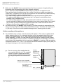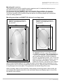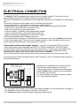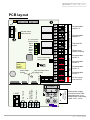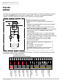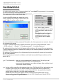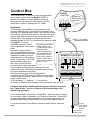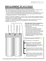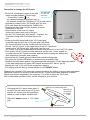
1
BANDIT 240PB Installation manual v.408
World leader in
active security
INSTALLATION MANUAL
BANDIT 240PB
UK 230 VAC
C
ONTENTS
Introduction ........................................................................................................page 01
Safety precautions ......................................................................................................03
Specifications ..............................................................................................................04
Mounting ......................................................................................................................05
Electrical connection......Main power.......................................................................... 08
PCB layout .........................................................................09
Inputs...................................................................................10
Outputs................................................................................22
Status communication ...Front LEDs...........................................................................32
Audio ...................................................................................35
Event-log ......................................................................................................................37
Passwords ...................................................................................................................38
Control Box ................................................................................................................39
HY3-pack replacement ...............................................................................................41
Maintenance.................................................................................................................43
First aid .......................................................................................................................44
Frequently asked questions & Schematic examples ...............................................45
BANDIT 240 PB v.408
INTRODUCTION
By selecting this device, you have acquired advanced active access-prevention technology.
With BANDIT we offer you an affordable system which guarantees operational reliability, top
performance and a discrete design.
More and more private and public buildings are being equipped with a protection system
against burglary. When armed, these systems detect a burglary attempt. The detection is
generally communicated by means of a siren and/or strobe or sometimes an automatic
phone call to an alarm control centre or police station. In real terms these notifications are
satisfying, but the subsequent human intervention often arrives more than 10 minutes
after the event! Burglars are aware of this and use this time to steal the most valuable
things and get away in time.
BANDIT offers a unique and active solution to this problem. For this system is totally capable
of filling a large office, store or other room, within a few seconds, with a non transparent fog.
This fog prevents persons from entering the room for at least 10 minutes after setting off the
alarm, since they cannot see a thing. The ejected fog has a soft mint smell (to avoid possible
fire interpretation by outsiders), it is colourless and leaves no traces. So the fog safely and
quickly disables the vision capabilities of unwanted visitors.
BANDIT is installed in those rooms that contain the most valuable objects; by doing so,
burglary damage is effectively limited to a strict minimum.
Advantages:
- Fills 1000 Ft³ (28 m³) of space per second of fog expulsion.
- Extremely compact and discrete design.
- A system free of maintenance with very high operational reliability (by lack of moving
components).
- The standard integrated “Power saver” and good thermal isolation, maintains a very
low energy consumption, between 30 and 40 W/h, depending on the adjusted fog
expulsion period.
- Continuous control of liquid level. When the level is too low to guarantee a full
expulsion period it will be shown by an LED and an electrical contact will occur. In this
case you’ll have to replace the internal HY-3 pack. The recognition and acceptance of
the new HY-3 pack (such as the resetting of the HY-3 shortage notification), occur
automatically. For recharging, the empty HY-3 pack has to be returned to your BANDIT
dealer.
- In case of interrupted power supply voltage (230 VAC), operation is guaranteed:
electronics ~24 hours, fog generator ~2 hours.
- The device is prepared through plug-in connectors, to be extended with a control box
and/or a wireless remote control.
- A powerful and flexible alarm central connection. With this the unit can be programmed
by means of a PC/laptop (Win95/98/2000/XP). This kind of programming facility offers
a comfortable and practically unlimited programming possibility.
- Includes a ‘real time clock’ and extended log for 1000 events, whereby every event is
documented with time and description of it. This electronic log is equipped with an
internal battery (10 years), in order to save all data in the event of a total power failure
occurs.
Introduction - p. 1
BANDIT 240 PB v.408
- The internal failure check system constantly controls the perfect operation of:
- the internal power fuses and heat fuses
- the power voltage of the 13,2 volt battery
- the communication with the HY-3 pack
- the status of the inputs and outputs
- the temperature of the heat exchanger, the HY-3 pack, and the PCB environment.
- the presence of power supply voltage.
- the internal tamper circuit (anti-sabotage circuit).
- By means of a connecting cable (communication link) between a IBM compatible PC or laptop,
you will be able to read out the unit (settings, log and/or internal values). The required CD with the
Bandit Software can be requested for free at your local BANDIT dealer, or can be downloaded from
our web site www.bandit.be. This program runs with Win95, 98, 2000 as well as with XP and offers
a friendly Windows like users program.
It is advised to perform a yearly fog generator test. See also Maintenance, page 43.
Standards:
- Complies with European CE and EMC Standards.
- Complies with International Standard: IEC 839-1-3
- Approved by the Belgian Ministry of Internal Affairs
- Complies with the British Standard: BS 7939 : 1999
- Complies with the Dutch Standard of the NCP: IOE 03301-M and IQA 06901-M
- Complies with the French Standard of the CNPP: test report n°AI 040006
approval n° 2004-0001
- Complies with the Danish Standard of the F&P: class 1, AIA 212
registration n° 10.212-00418
Industrial property:
- BANDIT is a registered trade mark.
- HY-3 is a registered trade mark.
- The BANDIT fog generator process is internationally protected by several patents.
Producer:
BANDIT nv./sa.
Nijverheidslaan 1547
B-3660 Opglabbeek
Belgium
C
H. R. Tongeren: 78.324
( : (32) 89 85 85 65
Fax : (32) 89 85 23 64
web : www.bandit.be
Text and drawings in this document are subjected to author protection.
Copyright: BANDIT NV, B-3660 Opglabbeek, Belgium.
p. 2 - Introduction
BANDIT 240 PB v.408
SAFETY PRECAUTIONS
Location:
- To prevent fire or shock hazard, do not expose this appliance to rain or moisture.
- Install the device in such a way to allow a good airflow.
- Only install the appliance as described, i.e. In vertical position, with the text on the
front panel being readable from the floor. The maximum angle of inclination is 15° to
the front and 10° in all other directions.
- System malfunction is possible at ambient temperatures above 50°C. Keep the appliance
away from heat sources such as radiators, heating elements, stoves or other heat
producing devices.
- The appliance is unexpectedly heavy, ~62 Lbs (28 Kg). It needs to be fixed on a sufficiently
solid surface. Use sufficiently strong fixing materials, preferably our 240 floor or wall
mounting, which are very solid and reliable supports for your unit.
Electrical connection:
- This appliance only operates on 230 VAC / 50 - 60Hz (210-240 VAC) supply voltage with
grounding. Always check the voltage on the rear cover of the device.
- This device has a max. Peak consumption of 3.5 A / 230 VAC. Use only power cable and
grounding of minimum 1.5 mm² (preferably flexible with end splices). Use the strain
relief which is ~0.5 In. beneath the entrance of the power supply input.
- If you detect a strange smell or smoke, the appliance has to be switched off immediately
by turning the main supply fuse to “off”.
- In case of doubt, immediately contact your BANDIT dealer or manufacturer, mentioned on
the back cover of this manual.
- There are no repairable components inside the appliance. Leave all repairs to authorised
persons and/or the manufacturer.
- The PCB contains a heat sink. On all parts and areas beneath and around this cooling
plate, there are uninsulated “dangerous voltage” points. This “dangerous voltage” can
cause electrical shocks.
- For further connection instructions, see page 8.
Cleaning:
- Do not use volatile fluids, such as alcohol, thinner, petrol or spirit to clean the outside
of the appliance. Use a clean, damp cloth.
- The black front textile has to be cleaned with a vacuum cleaner with soft brush mouth (dust
signs). The frequency of cleaning depends on the quantity of dust present in the room to be
secured.
Fog ejection control:
- The ejection nozzle is normally about 5°C warmer than the temperature of the environment,
so not warm enough to get burned by. However during fog ejection and the first two minutes
after, this nozzle can reach a temperature up to 120°C . Avoid direct contact with the nozzle
after a fog ejection to prevent skin burns.
- A fog ejection test only should be performed when:
a) All persons in the surrounding area and fire safety personnel have been notified, and
b) There is nobody in the immediate surroundings and/or direction of ejection.
- During a fog ejection test, it is prohibited to look towards the direction of the ejection nozzle
from a distance less than 25 Ft (8 metres).
Safety precautions - p. 3
BANDIT 240 PB v.408
SPECIFICATIONS
Descriptions:
- Dimensions:
- Weight:
- Max. Mains supply failure:
- Reaction time:
- Fog ejection image:
10.6 In. wide x 14.4 In. high x 10 In. deep.
62 Lbs (28 Kg).
Fog generator +2 hours and electronics +24 hours.
1 second between alarm signal and fog ejection.
Cone shaped straight ahead
(optional), or
60° wide coon
(R60 standard version)
Fog generator:
- Fog ejection capacity:
- Fog ejection pressure:
- Maximum fog ejection period:
- Warm-up time:
- Max./min. Environmental temp.:
- Maximum heat loss:
- Heat exchange capacity:
- Nominal ejected droplet size:
1000 Ft³ filling of space / second with 1 Ft. eye
object.
230 PSI (1.6 Mpa).
18 seconds.
50 minutes from cold condition.
maximum 50°C / 120°F and minimum 0°C / 30°F.
40 W/hour.
18 kW/hour.
section 0,000016 In. / 0.004 mm (full aerosol).
HY-3 pack:
- HY-3 fluid contents:
- Nominal working pressure:
- Maximum allowed internal pressure:
- Construction material:
- Build-in electronics:
1.4 litre (0.37 gal.).
230 PSI (1.6 Mpa).
870 PSI (6 Mpa).
rvs 304L and aluminum AlMgS1.
digital temperature sensor and analog/digital
E²prom memory level.
tamper switch and control LED.
integrated propellant-expulsion security
direct working 12 V NC valve.
Electrical:
- Min./max mains power supply:
- Nominal 12 V low voltage:
- Max peak current at 230 VAC:
- Average power consumption:
- Capacity heating element:
- Inputs:
- Outputs:
- Current back-up:
- Power control:
- Electronics:
p. 4 - Specifications
210 to 240 VAC at 50 to 60 Hz.
13.1 V DC from 0 tot max. 500mA load.
3.5 Amps.
40 W/hour.
750 W.
all inputs are insulated by an opto-coupler.
all outputs are potential free relais contacts
12 V / 2 Ah (sealed lead acid battery).
Pulse width modulator (PWM) through zero-cross triac.
Flash micro-controller, Platina Pt1000 sensor converter,
time/date clock with back-up battery and 64K E²prom.
On board communication with HY-3 pack
On board communication: 6-way connector for
connection to "Control Box" and 5-way plug for
wireless remote control.
Serial communication with communication link
BANDIT 240 PB v.408
The unit is packed in a cardboard box:
15.35 x 15.35 x 1.57 In. which contains:
- BANDIT 240 PB device.
- double sided warning sticker “Burglary...”
- this installation manual.
- "HY-3 grip" tool
MOUNTING
+ 2 In.
As a professional, you’ll have to consider properly, what would be the most effective place to
install the appliance. Here are some guidelines which can help you with your decision:
þ Logically, you’ll place the appliance so that the fog expulsion points in the direction of the
supposed burglary entrance or in the area which contains the most valuable objects.
Should this entrance provide a potential big air passage to outside (i.e. a garage door,
a glass frontage which is sensitive for break-in, etc.), You’ll have to prevent the ejection
nozzle being pointed in this direction to avoid the potential fog ejection to be blown
outside. In this case, you’ll have to point the nozzle towards a side wall to break the
ejection pressure. This way, the fog will “cloud out” and only a little amount of
fog will be blown directly to the outside.
þ Avoid the ejected fog forming a oneway trap. The ejected fog is supposed to form a
strong take-away reducing barrier. Burglars are not supposed to be caught.
Further, if there is a false alarm, the chance to catch innocent persons, is bigger than to
catch burglars in a real burglary!
þ Determine the place in such a way that the ejection nozzle does not point in the direction
of fragile objects. The powerful fog expulsion could blow down these objects.
þ There has to be a free passage area for the ejected fog, of at least 20 Ft. before it
bounces against a fog blocking obstacle, i.e. a front wall. The space of about 20 Ft. in
front of the ejection nozzle will be the first to be filled out with fog, and this within 2
seconds.
þ If there are already PIR-sensors installed in the
room to be guarded and you don’t want to take
any risks with false triggering because of fog
Ceiling
expulsion, you’ll have to replace these PIR’s
with combo-sensors (PIR/radar). If you have to
install a new installation, use combi-sensors for
volumetric detection in ereas where BANDIT is
installed. Radar never detects floating clouds,
Keep a minimum of
most PIR’s do sporadically.
1 Ft. of space at the
þ Make sure that no burglar can come near the
left hand side of the
unit,in order to open
unit without being detected first by a sensor.
the hatch to the
This sensor has to start a fog expulsion,
HY-3 pack.
independently of an eventual entrance delay.
Appliance slightly
inclined forward ~ 5°,
maximum 15°
Wall with
concealed
wiring or
groove
Mounting - p. 5
BANDIT 240 PB v.408
þ Make sure the BANDIT is firmly secured to wall or floor, to prevent a burglar with prior
knowledge from throwing the unit quickly through a window.
Use an optional available BANDIT wallmounting to install the unit against a wall:
There are two kinds of wallmounting: flat or swivel. Use the re-usable mounting help
“Handy boy” to install the unit, as this tool carries the unit and makes it possible that any
person can install the device easily by himself.
- For wallmounting against a solid brick wall, use plugs and screws supplied within
- For wallmounting against a double plaster wall, use special metal plaster-plugs
available in any hardware store.
- For wallmounting against a single layer plaster wall: install the unit only in an inner
corner and order in addition an optional plaster inner corner support plate. Don’t install
the unit with a normal wallmounting against these kind of walls to avoid the device
falling on the floor after a while, due to its weight.
þ For floor mounting, use BANDIT floor mounting. This floor mounting is screwed into the
floor or stuck to it with included double-sided adhesive tape. The device is installed at 2
In. (50 mm) off the floor to avoid possible damage due to cleaning tools or water.
Hidden mounting of the appliance
For installation into a closet, order the device with option /L. This unit is supplied with 4
rubber supports (feet), a 2 In. extended ejection nozzle (a standard closet door has a
thickness of approximately 3/4 In). and a heat resistant black door rosette (ejection
nozzle passage). This way you can hide the device and at the outside only the rosette
will be visible. Make sure you provide a ventilation grid above and beneath to avoid too
much rising of the temperature in the closet due to BANDIT ‘s heat loss. With an ambient
temperature above 50°C / 120°F, the unit will activate its technical output [Okout] and you
can expect damage on the internal lead battery.
F
Do not use any other rosette than the
one supplied with the unit. The supplied
rosette is made of a special heat and
steam resistant material. Fix the rosette
by using the special nut delivered with
it.
Rosette
assembly nut
M50 x s. 1.5
Cabinet door
þ
Black finish
rosette
Ejection nozzle, available
in R/60 or R/0 (straith) version
Hole drilled through
cabinet door
(hole saw dia. 2 In.)
Cabinet schelf
max. 1” (24 mm)
p. 6 - Mounting
4 rubber feet
BANDIT 240 PB v.408
Mounting aid: handy boy.
This optional tool is used to install the device against a wall. It is attached with two pins to
the wall mounting and so it makes a solid shelf.
On this temporary shelf, BANDIT is wired and adjusted. After installation, the two pins
are pulled out, releasing the handy boy, so it can be used again in the next installation.
You’ll save yourself a lot of trouble to keep the device at a working height while connection
works are being performed.
Mounting more than one BANDIT 240 devices in one large room.
Example of mounting in a shop of
6980 Ft². Fog image after 8 sec. of
fog expulsion.
Example of mounting in a shop of
1980 Ft². Fog image after 8 sec. of
fog expulsion.
60 Ft.
33 Ft
Fog flow
115 Ft
60 Ft
flo
F og w
The BANDIT 240 has a room filling capacity
of ~1000 Ft³ per second. This corresponds with
~100 Ft²/sec. The max. surface area which
can be secured with one device is equal to
the max. fog expulsion period = 18 s x 100 Ft²/s
which is 1800 Ft². For larger surfaces, such as:
large shops and office spaces, one has to
install more devices, one device each 1500 Ft²
with a normal ceiling height of 9 Ft. Install the units in such a way that the fog stream of one
device points next to, but not in the direction of the next unit. This way, there is a round stream
of fog throughout the entire place. This guarantees the fastest filling of the room.
While mounting, keep in mind to provide a free passage for the fog stream. After a while, the
store keeper has forgotten about the units and stacks boxes and displays right in front of the
fog ejector of the devices.
p. 7 - Mounting
BANDIT 240 PB v.206
ELECTRICAL CONNECTION
The BANDIT 240PB is equipped with simple and yet versatile interface. This version is only
programmable through PC or laptop using the communication link.
This unit is intended to be connected to an existing alarm system or be installed as a stand-alone
unit.
The build-in electronic system takes care of controlling and securing:
- the fog generator (3 x temperature + frequency control of valve).
- tamper switch of the rear cover, HY-3 pack hatch and optional connected "Control Box".
- control of front- and PCB LED, and internal siren.
- read out of inputs and jumper adjustments.
- control of tamper-, technical- and programmable outputs.
- control of internal battery, glass fuses and internal fan.
- digital and analogue communication with the HY-3 pack.
- serial communication with PC/laptop (com port)
The complete electrical system is accessible by removing the rear cover of BANDIT (unscrewing
4 x M4 cross head screw). The rear cover is tamper secured, so be sure that the unit is not in
guard mode and that the control room (optional) is warned.
Connection on the main power supply: on the left, beneath the PCB, you’ll find a
3 way terminal block with integrated main fuse. The PCB is marked with “230 VAC supply”.
Connect the left connector strip (N) to the mains neutral (blue or white wire), the middle one to
the green-yellow ground wire and the right connector (L) to the mains phase (black wire).
Switching phase and neutral has no effect to the function of BANDIT .
The unit is secured for mains failures and can be practically seen as an Ohmic power load.
Connect the power cable through the strain relief connector (~0.5 In. beneath the left entrance in
the metal back frame).
F1 4AT
Power supply glass fuse (5 x 20 mm)
F1 = 4 AT slow
N
230 VAC
Power supply
L
+
- Preferably use a separate fuse, directly coming
from the main power supply or connect to
existing power circuit of installed controlling alarm
system (BANDIT has a peak current consumption
of 3.5 Amps. for each unit).
- For easy installing, use flexible connection wires
3 x 1.5 mm² with end splices.
-
12 V
500 mA
Supply
- For complete PCB (printed circuit board) layout with description of connector strips, see page 9.
- For properties of the in and outputs, see page 10 through 31.
- For detailed description of LED functions, see page 32 through 34.
p. 8 - Connection to main power supply
BANDIT 240 PB v.408
+
Real Time
Clock
click-on
battery
+
-
red
JMP
F2
+
500mAT
+
-
Non-touchable mains
voltage zone
Yellow PWM
heating
Led
outputs: maximum 24 V / 1A.
Programmable
output n° 1
Technical OK
output
Tamper loop
output [Tmpout]
inputs: 12 V = / 10 mA.
-
Rear cover tamper
spring switch
+
-
c
Black
Yellow
Blue
Green
White
Red
Programmable
output n° 2
Programmable
input n° 4
Programmable
input n° 3
Programmable
input n° 2
Programmable
input n° 1
12 V =
c
6 x Control box
PCB connector
500 mA. X+ X- X+ X- X+ X- X+ X- Ta Tb com nc no com nc no com nc no
Supply
Xin3
Xin4 Tmpout
Xin1
Xin2
OKout
Xout1
Xout2
c
6.3AT
Remote control
PCB-connector
12 VDC supply
(max. 500 mA)
N
Mains power supply
connection block with
integrated fuse (4 AT)
Mains power connecting
cable, min 1.5 mm²
N
N
230 VAC
Power supply
L
Prim. transfo
Heater 750W
heatexchanger
1.25AT
Sec. Transfo
F1 4AT
F4
F3
PCB layout
p.9 - PCB layout
BANDIT 240 PB v.408
Inputs
All inputs are equipped with opto-couplers, which provide care of a perfect separation between
the internal BANDIT electronics and the “outside world”. This way, all unwanted disturbing
signals, caused by lightning, induction or R.F. tensions, are kept outside.
Scematic display of an input
Schmitt-input
Electrical properties of an input:
- polarised (+ and - signs beneath connectors on
PCB.
- secured for possible polarity reverse and equipped
with RC- and LC- filter.
- an input has to be stable for at least 0.2 seconds
before the new situation is accepted.
- the connected voltage can be either from an external
source or from the 12 V BANDIT supply source
itself [Supply].
- the input current with 12 V is ~ 10 mA each input.
- each input is equipped with a Schmitt-input, after
the opto-coupler. The trigger voltage is approximately
6 V with hysteresis of + and - 1V. This way,
unreliable input voltages are being avoided
as much as possible.
ground
Aircoil
opto
1K
-
+
11
15
1
5
After adjustments: check the voltage over
the inputs.
- Consider < 2 V as no volts.
- Consider > 9 V as 12 V .
Voltages between 2 and 9 V are not normal
and will cause problems sooner or later.
V=
The device, model 240PB , is equipped with 4 inputs. The function is determined by selecting
the desired function trough PC/laptop.
Programmable inputs
+
-
+
-
+
-
+
-
+
-
c
c
c
500 mA. X+ X- X+ X- X+ X- X+ X- Ta Tb com nc no com nc no com nc no
Supply
Xin3
Xin4 Tmpout
Xin1
Xin2
OKout
Xout1
Xout2
12 V =
outputs: maximum 24 V / 1A.
Programmable
output n° 2
Programmable
output n° 1
Technical OK
output
Tamperloop
output [Tampout]
Programmable
input °. 4
Programmable
input n° 3
Programmable
input n° 2
Programmable
input n° 1
12 VDC supply
(max. 500 mA)
P. 10 - Inputs
inputs: 12 V = / 10 mA.
BANDIT 240 PB
v.408
Possible software settings for the inputs.
On each of the four physical inputs [Xin1] to [Xin4], there can be assigned a function. To
simplify the human interpretation concerning the inputs while reading them out, each input
can be appointed with an alias (nickname) (e.g. [Xin2] = “PIR sensor entry”).
Following, you’ll find an overview of the possible settings, offered by the BS-software. In the
help-function of this BS-software, you’ll find more and detailed information for each function.
No function:
The input is totally ignored by the software.
F
Make a habit to assign a ‘no function’ to not connected inputs (floating).
This way you’ll make sure, this input is really ignored all the time.
Guard:
This function reports to BANDIT that the selected input has been assigned as guard input
[Grdin]
The guard input arms/disarms the unit . Only if BANDIT is in "guard mode" is it possible to
switch to “alarm mode” by activation of the alarm input(s).
Properties of the "guard mode":
4The red LED "Guard" on the front panel will be on as long as the unit is in “guard”
mode.
4Eventual LED-warnings on the front panel such as: failure, HY-3 and power? Will be off
under any circumstances. The green OK-LED on the front panel remains on. This way,
a unit which is switched in "guard mode", will never show to the outside world that it
might have a technical problem.
4The functional properties of a guard input are also determined by clicking on R the
optional settings, e.g. an alarm input (see next page). This way, a unit can refuse to
switch on to guard mode, because of an active alarm input at the moment of switching
into guard mode.
Activating the guard input [Grdin]:
This input can be activated by means of 12 VDC or no voltage over the input, as well as
by means of a pulse on/off activation through a negative
or a positive
edge.
F
If an optional remote control is connected, and channel 1 and/or 2 of this remote
control is set as guard input, the guard function cannot be set onto inputs [Xin1]
to [Xin4].
F
To avoid activation conflicts, only 1 input can be appointed with the guard function.
p. 11 - Inputs - Functions
BANDIT 240 PB
v.408
Alarm:
This function reports to BANDIT that the selected input has been assigned as alarm input
[Alin]
Only if BANDIT is in "guard mode" is it possible to switch into “alarm mode” by activating
the alarm input(s) (starts actual fog ejection).
Properties of the "alarm mode":
4The red LED "Alarm" on the front panel will be on the moment the "alarm mode" starts
and off as soon as the unit is switched to guard mode off (see page 11 "guard mode").
4The moment the "alarm mode" starts, there will be a fog expulsion (selected fog
ejection period). A running fog expulsion can only be interrupted by switching the unit
to guard mode off through the guard input. After a fog expulsion, there will be added 3
minutes as ‘dead period’ or auto-reset period. A new alarm pulse (edge) on an alarm
input after these 3 minutes, will start a new fog ejection period. See also page 19,
under temperature protection.
4With the alarm mode, also the integrated siren starts to sound. The volume as well as
the period of sounding can be set: - ; speaker - ; alarm siren
Activating the alarm input [Alin]:
Depending on the software settings, the alarm input can activate the alarm mode through
a negative
or a positive
edge.
F
If the optional remote control is connected, channel 1 and/or 2 can be set as
additional alarm input(s).
F
Using the software additional options can be assigned to the alarm input.
Possible options for an alarm input:
R The use of an input delay.
If an input delay is set, the clicking on (check mark in the box) of this option will
determine if this input delay is valid for this alarm input.
R The use of an output delay.
If an output delay is set, the clicking on of this option will determine if this output
delay is valid for this alarm input.
R Confirmation required.
If an input is set as confirmation input, the clicking on of this option will
determine whether this confirmation input has to be activated as a condition to
proceed as a valid alarm when there is an incoming alarm signal over this
alarm input.
R Can switch into guard mode while an alarm input is activated.
Clicking on of this option determines whether the unit can switch to guard mode
while this alarm input is activated.
R There can be also set an additional fog ejection period on each different input. A
magnet switch sensor on a garage door can require a longer fog ejection period
than a sensor on a relatively smaller back door.
p. 12 - Inputs - Functions
BANDIT 240 PB
v.408
Doorbell:
This function reports to BANDIT that the selected input is determined as a doorbell input.
As long as BANDIT is switched into "guard mode", this input has to be seen as a normal
alarm input.
However, as long as BANDIT is not switched into "guard mode", the activation of this unit
will only result in a sound generated by the unit (doorbell).
Properties of the "doorbell mode":
4While the unit is switched into guard mode:
The input behaves itself as a normal alarm input, with the same functionality and the
same optional settings.
4While the unit is not switched into guard mode:
The activation of this input starts a doorbell sound. The volume as well as the period of
this audio signal can be set - ; internal speaker - ; doorbell.
When an output is determined with the function of ‘doorbell output’, this output will be
active as long the doorbell audio signal is heard.
Activation of the door bell input:
4While the unit is switched into guard mode:
Depending on the software setting, this input can activate the alarm mode with a
negative
or a positive
edge.
4While the unit is not switched into guard mode:
Depending on the software setting, this input can activate the doorbell mode with a
negative
or a positive
edge, as well as through a level activation (0 or 12 volt
is active). The doorbell mode is activated as long as the input is activated.
F
This input function can save you a complete doorbell system. The same sensor
(conforming to normal security requirements) can be used as alarm sensor as
well as complete doorbell system.
F
The activation of the doorbell input while the unit is not switched into guard
mode, will not be written in the log.
p. 13 - Input - Functions
BANDIT 240 PB
v.408
Panic:
This function reports to BANDIT that the unit has to immediately perform a fog expulsion.
The panic mode can be activated independently of guard mode, delay settings or
confirmation requests. Normally, this input function is used to connect a panic switch to it.
Properties of the "panic mode”:
4 The red LED "Alarm" on the front panel will be blinking, as long as the unit is switched
into panic mode.
4The moment the "panic mode" is activated, there will be immediately a fog expulsion
(the fog ejection period can be set seperately). A running panic mode fog expulsion
can only be interrupted by switching off the panic mode itself.
4When a fog expulsion is finished and/or interrupted and a new panic mode is activated,
a new panic fog expulsion period will start. See also page 19, under temperature
protection.
4If an output is determined as “panic output”, this output will be active as long the panic
mode is activated.
4The moment the panic mode is activated, the internal siren of the unit will sound. The
volume as well as the sounding period of this panic siren can be set:
- ; speaker - ; panic siren.
Activation of the panic input:
Depending on the software settings this input can start or interrupt the panic mode.
F
Using the software additional options can be assigned to the panic input.
Possible options for a panic input:
R Can switch Panic ON.
An active edge (pulse) switches the panic mode on (
or
).
R Can switch Panic OFF.
An active edge (pulse) switches the panic mode off.
- A panic switch whereby both options are clicked on for this input, has the
possibility to either start (1st pulse) or stop (2nd pulse) a panic mode.
- A panic switch whereby only the option ‘Can switch panic on’ is clicked on for this
input, can only start a panic mode.
- A panic switch whereby only the option ‘Can switch panic off’ is clicked on for this
input, can only interrupt a running panic mode (e.g. key switch).
Silent panic:
If this ‘silent panic input’ is activated, the unit only reacts by activating the output which is
determined as ‘silent panic output’ during R 3 or R 60 seconds (mostly used for telereporting).
Of course this event will be saved in the log.
p. 14 - Inputs - Functions
BANDIT 240 PB
v.408
Activation of a silent panic input:
Depending on the software settings, this input can start the silent panic mode with a
negative
as well as with a positive
edge.
Warning:
This function reports to BANDIT that the selected input is determined with the function of
warning input.
When this input is activated while BANDIT is in "guard mode" , the unit will sound it’s
internal siren and the event is saved in the log. Normally this input function is used to
connect a sensor with it, pointed in an area where there is a major possibilty of accidental
staff movement, such as the entrance hall of a public office. Instead of the member of
staff causing a false alarm, he’s going to be warned loudly that the alarm system is still in
guard mode.
Properties of the "warning mode”:
4If the function of an output is determined as ‘warning output’, this output will be active
as long as the warning mode is activated.
4The moment the warning mode is activated, the unit will have it’s internal siren
hollowing. The volume of this temporary warning can be set. - ; speaker; warning siren.
Activation of this warning input:
Depending on the software setting, this input can start a warning mode with a
negative
or a positive
edge or a setted active voltage level (0 or 12 VDC).
p. 15 - Inputs - Functions
BANDIT 240 PB
v.408
Fire alarm on:
If applicable for the system, this type
of input is connected to a thermal fire
detector or with the output of a fire
detection central. In case of a fire,
not only will the fire detection system
notice the fire, but also the burglary
detection will probably switch into
alarm mode, this because of the
incorrect information received from
e.g. the PIR-sensor detecting the
moving heat from the fire or any
people entering the premisis.
In case of a fire, most probably there
will be also a fog expulsion. This
type of input will prevent this
awkward and unwanted situation.
i Thermal fire detector
Common used fire detectors can be stated in 3
major categories:
- Optical fire detector: is in fact a smoke detector.
Smoke changes the light reflection properties of
the air. This changement in light reflection will be
noticed by an opto-electronic transmitter-receiver
and reported as a smoke detection. Reacts on
fog expulsion and causes fals smoke alarms.
- Ionic fire detector: is in fact also a smoke detector.
Smoke contains chemical waste particles, which
are produced as a result of burning. A slightly
radio-active element notices this specific air
pollution and this will be reported as a smoke
detection. Reacts on fog expulsion and causes
false smoke alarms
- Thermal fire detector: Reacts only on a relatively
fast temperature change and an absolute
maximum temperature at the ceiling. Doesn’t
react on fog expulsion.
Properties of the ‘fire alarm on mode’:
4The unit will in any circumstances refuse to perform a fog expulsion. Even an eventual
panic input will be totally ignored.
4The moment the fire alarm mode is active, the unit will sound through its internal siren.
The volume of this temporary warning can be set.- ; speaker - ; fire siren.
4If a fire alarm mode output is set, this output will be active as long as the fire mode is
valid.
4If the “fire alarm on” input is selected with a voltage edge (pulse) operation, it is
necessary to select also an input as “fire alarm off” to be able to switch off the fire
alarm mode by p.e. key switch.
4The blocking of the fog expulsion will be only removed when the unit is subsequently
switched into guard mode.
Activation of the fire alarm on input:
Depending on the software settings, this input can start the fire alarm mode when:
- A negative
or a positive
voltage edge (pulse): an active puls will switch on the
fire mode. Following pulses have no influence. The software is going to force you to
select also a “fire alarm off input”. This input is described on next page (p17).
- An active voltage level (0 or 12 V): As long as the voltage is active, the fire mode will be
active. The setting of a “fire alarm out” input is not required. However, if there were
selected a ‘fire alarm out’ input, the status of this input would depend on the ‘off status’
of the fire alarm on mode. See next page (p 17)
F
See also next page: fire alarm off input
p. 16 - Inputs - Functions
BANDIT 240 PB
v.408
Fire alarm off:
If applicable for the installation, this input type will be connected to a fire alarm off switch
(usually a standarised switchbox that can be opened by fire brigade or other authorised
people to switch off the fire alarm) or to the output of a fire detection central.
Properties of the “fire alarm off” input:
4Has priority on the “fire alarm on” input. As long as the status of the “fire alarm off”
input is active, the unit cannot be switched onto the fire alarm mode and an eventual
active fire alarm mode will be interrupted.
4A “fire alarm off” input can only be selected when there is also a “fire alarm on” input
selected.
4The switching off of the fire alarm mode does not mean that the fog expulsion blocking
is switched off. The fog expulsion blocking will only be switched off, the next switching
into “guard mode” through the guard input or by activating a programmed panic input.
Activation of the fire alarm off input:
Only 12 volt voltage level control is possible. This means that 12V over this input will
reset the fire mode as a priority.
p. 17 - Inputs - Functions
BANDIT 240 PB
v.408
Confirmation:
This input reports to BANDIT that there is a permission to proceed to the “alarm mode”.
The meaning of this input function is as follows:
To postpone the transit to alarm mode, until a local zone detector confirms the burglary.
For example: the alarm system is in alarm because of detection of burglary at the back
door (confirmation input activated by means of the alarm system). BANDIT however, will
only switch to it’s “alarm mode” if the burglar enters the zone “private-office” , because
the PIR/radar detector on that location will transmit an active pulse to the alarm input on
which it is connected.
Properties of a confirmation input:
4Only if an alarm input and a confirmation input are simultaneously active + 0.3 s, while
the unit is in guard mode, BANDIT will switch to the alarm mode. Once in the alarm
mode, the status of the alarm input and/or the confirmation input have no influence
anymore on the sequence of the alarm cycle.
Activation of the confirmation input:
Only voltage level control is possible. Depending on the software settings, 0 V or 12 V
can be set as active.
F
F
Only one input can be determined with the function of confirmation input.
F
Each input which can start a fog expulsion (with exception of the panic input(s)),
has a clicking on option: R confirmation needed.
- If this option is not clicked on: the stated input can start the alarm mode.
- If this option is clicked on: the stated input will need a confirmation before the
alarm signal will be treated as a valid alarm signal.
If a confirmation input is activated while the unit is in guard mode, this event will
be saved in the log (the moment of activation as well as the moment of
desactivation).
Tamper input:
Alarm Tamper (no voltage
input input
= active)
Supply
This function places the input, as if it were a seperated
relay contact, in serial with the existing tamper-relay
circuit [Tmpout].
In high-risk installations, the fixed defined output [Tmpout] is
integrated in the tamper circuit of the existing alarm system.
If it is required that e.g. the BANDIT-related confirmation
sensor also has to be “tamper”-protected, an input can be
determined as tamper input.
The connection of the sensor will be wirde in such a way
that the input will not be active as long as the sensor
tamper contact is closed.
If this input becomes active, this will result in the switching
to ‘rest condition’ (COM and NO open) of the [Tmpout]
contact.
p. 18 - Inputs - Functions
Xin1
12 V =
+
-
Xin2
Xin3
Xin4
inputs: 12 V = / 10 mA.
+
-
-
+
+
-
+
Ta Tb
-
+ Alarm Tamper
Sensor
Tmpout
BANDIT 240 PB
v.408
Properties of the tamper input:
4As long as this input is active, the relay [Tmpout] will be switched onto rest situation
(contact Ta and Tb open).
Activation of the tamper input:
Only voltage level control is possible. 0 V is factory (fixed) set as active (tamper problem).
F
Only one input can be determined as tamper input.
Internal siren:
The unit 240PB comes with an integrated internal siren. This siren is automaticaly
activated with different modes (each mode has its own siren or beep sound). The
“internal siren”-function gives you the possibility to control this siren also from “outside”
through a selectable input.
Properties of the "internal siren” input:
Has the priority on all other siren sounds (with the exception of fire mode on).
4The volume of the internal siren can be set:
- ; speaker - ; internal siren.
4The internal siren sounds as long as the internal siren input is active, but the internal
Bandit-electronics will reduce the audio volume after 3 minutes of sounding, to 50%
(battery saving).
Activation of the internal siren input:
Only voltage level control is possible. Depending on the software settings, no voltage
(0 V) or 12 V can be set as active.
External alarm:
This special input function offers a fine solution for some special requests to the security
installer. It’s obvious a BANDIT-fog generator is installed in locations where “ram raid”
sensitive, high value goods should be protected. Sometimes, there is also the need to
overview and guard an external contact.
For example: a min/maximum temperature thermostat in a computer-server room,
whereby the over or under temperature limit exceeding has to be logged, mains tension
independent. As a warning, the siren has to sound and a contact has to report the
technical alarm.
The input function “external alarm” could offer a very cheap and fine solution for such a
problem.
p. 19 - Inputs - Functions
BANDIT 240 PB
v.408
Properties of the external alarm input:
As long as this input is active:
4The internal siren will sound.
4The time of activation as well as deactivation of this input will be logged.
4If an output is determined as “external alarm output”, the related relay will be active as
long as the external alarm input will be active. See p. 30
Activation of the external alarm input:
Only voltage level control is possible. Depending on the software settings, 0 V or 12 V
can be set as active.
F
Only one input can be determined as external alarm input.
p. 20 - Inputs - Functions
BANDIT 240 PB
v.408
On the back frame of the unit, you’ll find a female mini-jack connector mounted and
sunk-in. This extra protected, special input, has as feature to be the serial read-in and
read-out communication channel to a PC/laptop.
- Batteries included and
mounted ready to go.
- 2 spare batteries added
in the box.
The PC-communication link is a tool every
BANDIT-installer has to use to have a data connection
between BANDIT and a computer with a standard COM
port (RS-232 SubD connector). To perform the software
settings as well as to read-out the log of the 240PB, you’ll
need this “Communication link”. It has to be plugged-in,
on one side in the fog generator to be set and read-out,
and at the other side into the computer.
4 Fits to every PC/laptop (standard RS-232
/SubD9 connector).
Sunk-in
mini-jack connector
Communication Link
4 Is compatible with the “old” 220 BANDIT-model.
4 Safe, disturbance free and galvanic separation
between fog generator and PC or laptop
(+2.000 Volt secured opto-coupled data split).
4 BS-software CD included in box or upgradeable
through: www. bandit.be
Frontpannel Communication Link.
Laptop
BS-software
Green Led: Link on/off
This Led is on, the moment there is
communication, until 10 seconds after the
last communication signal.
If this Led blinks, both batteries have to be
replaced (Sony CR2430 or compatible).
Yellow Led: RS-232 communication-Led.
Blinks simultaneously with the
communication signals coming from the
PC/laptop. Blinks only when the chosen
COM-port of the PC/laptop is right set.
- 7 BS-software - ; option - ; comport
p.21 Inputs - Communication Link
BANDIT 240 PB
v.408
Outputs
The unit has a total of 5 outputs:
1. The 12 volt supply output [Supply1] (fixed defined). See further this page.
2. The tamper loop output [Tmpout] (fixed defined). See page 23.
3. The technical failure report output [OKout] (fixed defined). See page 24.
4 - 5. These are programmable outputs [Xout1 and Xout2]. Like the inputs, the
function of each of these outputs, depends on the set function selected through
PC/laptop.
Following, you’ll find a complete description of the properties of the different kind of
outputs.
Output: 12 VDC supply [Supply]:
Block scheme BANDIT low voltage circuit
230 V
50-60 Hz
F4
1.25 AT
16 V
1A
F3
6.3 AT
U = 13.3 V
I = cut 1.05 A
12 V / 2 Ah
line filter
F2
500 mAT
F1 - F2 - F3 - F4 :
Glass fuse 5 x 20 mm
12 V / 500 mA
[Supply]
MCU fusedetection
The [Supply] output can give a maximum of 500 mA (restricted by F2). In normal
conditions and with a full charged battery under charging current, the voltage is ~13 volt.
This voltage is practically ripple free (5mV ripple) and serves as supply for small
external current consumers, such as extra interior siren, Jumbo-LED and PIR-sensors,
and also as useful supply voltage for external relay contacts, to resend voltage signals
to the unit’s inputs.
The presence of this 12 V and good condition of F2 is continuously checked by the internal
BANDIT-electronics.
As a precaution make sure this [Supply] output isn’t loaded continuously with more
than ~450 mA.
It is very important never to connect BANDIT’s supply with the supply of a controlling
F alarm
system or any other device which have their own supply.
Even the grounds may not be connected to each other. This could result into
unexpected ground loops (high potential differences, especially with lightning and
similar over voltages) with all bad consequences following.
p. 22 - Outputs - 12 VDC output [Supply]
BANDIT 240 PB
v.408
Output: tamper loop [Tmpout]:
The terminals of [Tmpout] are connected with the COM and NO contact of a relay.
As long as this relay is active, both contacts will be closed. The status of this relay is also
determined through the MCU (Micro Controller Unit).
Block scheme BANDIT sabotage loop (tamper)
Internal
tamper
side hatch HY-3 pack
12 V
0V
0V
Relay
12 V /
1A
Max:
500 mA./
12 Volt
Ta Tb
Tmpout
Internal
tamper
back cover
MCU
0V
0V
N.O.
Tamper wire in cable
BANDIT 240 Control Box
1K
Programmable input
function: tamper input
H
Y3
OK
test
HY-3 pack level / niveau / livello
90
+
tech out
test
60
30
0%
-
X+ X-
The MCU has as tamper related inputs:
- 2 permanent inputs: a) Internal tamper from the side hatch of the HY-3 pack, and
b) the internal tamper spring on the back cover.
- 1 input from the tamper wire in the cable coming from an eventual connected ControlBox. This tamper cable will only be “seen” if a Control- Box is really connected and
the “Control Box = present” is set.
- 1 input from a programmable input eventual set as tamper input. See p. 18.
Based on the info of these different inputs, the MCU software will decide whether to activate
or not to activate the [Tmpout]-relay.
Properties of the tamper mode:
- The [Tmpout] relay is in rest position (Ta and Tb open).
- The moment a tamper mode starts or ends is kept in the log, together with which tamper
contact or tamper input has caused this tamper mode.
- Only if:
a) Only if the click on option’ R Tamper mode can start alarm mode’ is clicked on,
(7 BS-software - ; Settings - ; Tamper mode), and;
b) the tamper mode is being activated while the unit is in “guard mode”,
the tamper mode will also be able to switch the unit into alarm mode.
p. 23 - Outputs - Tamper loop [Tmpout]
BANDIT 240 PB
v.408
Application of the tamper circuit:
In a traditional installation the tamper output [Tmpout] is taken into the main tamper loop of
the existing alarm system (zone: tamper fog generator).
BS-software gives you the possibility to bridge the HY-3 pack side hatch tamper
F The
contact e.g. when opening this hatch to change the HY-3 pack without causing a tamper
alarm - 7 BS-software - ; HY-3 pack - R Software HY-3 pack side hatch switched off.
BS-software gives you a complete overview of the different tamper possibilities
F The
- 7 BS-software - ; Bandit - ; System check.
There is also a manual possibility to force the output [Tmpout] by mouse clicking on ¤, off ¤
or automatic ¤.
p. 24 - Outputs - Tamper loop [Tmpout]
BANDIT 240 PB
v.408
Output: Technical failure output [OKout]:
The 3 terminal connectors of the [OKout] are connected with the COM, NC and NO contact of a
relay. The MCU determines, following the incoming signals from the failure detection electronics,
the status of this relay.
Block scheme BANDIT Technical output (OKout)
Electronic circuits
for detection of
technical failures
12 V
0V
Relay
12 V /
1A
c
MCU
Max:
500 mA./
12 Volt
com nc no
OKout
Log page
Log page
Log page
Log; technical failures
As long as the internal BANDIT-electronics don’t detect an internal failure, this relay will be
activated (COM and NC open).
As long as there is detected a failure, the [OKout] contact will be in rest (COM and NO open).
Following, you’ll find an explanation of the different possible internal failures the BANDIT
electronics are able to detect:
4The glass fuse F2 (500 mA from [Supply]) is interrupted.
4The glass fuse F3 (6.3 A battery fuse) is interrupted.
4There is no battery or the voltage of the battery is too low.
4The ambient temperature of the mounted HY-3 pack exceeds 120°F.
4The heat exchanger can not reach its goal temperature. This can mean:
a) the internal over temperature fuse is interrupted
b) the heating element from the heat exchanger is faulty
4The internal fan doesn’t run properly.
4The unit is asking for more than 7 days to exchange its HY-3 pack. This item however is
not a real failure, but an abnormal situation whereby the reliability of the unit is endangered
because of to little amount of fog liquid in reserve. See also page 24, changing HY-3 pack.
4There is a lack of main power supply for more than 15 minutes (main power or main fuse
F1).
4The MCU measures unrealistic values through its sensor inputs.
OK
4Through a connected control box, an internal failure can be simulated techtestout .
p. 25 - Outputs - Technical failure output [Okout]
BANDIT 240 PB
v.408
H
A few examples:
- Through the software forced outputs [Xout], [Okout] or [Tmpout]
- Eventual invalid settings
- Fog ejection blocked because of.
- Red jumper not connected.
- Through software in ‘System control’ screen R, see p. 24.
- Through the “Control Box” switch
- Wrong or invalid HY-3 pack (e.g. : Demo HY-3 pack in a regular device).
- Tamper contact of the side hatch is bridged through the control box switch
through software ( R HY-3 pack screen).
Y3
An abnormal setting is valid for more than 3 hours. This setting is shown on the front led
‘Failure’ which will be blinking fast.
and/or
As soon as the internal failure is restored, the failure report will automatically disappear and
the normal situation returns: [OKout] active (COM and NO closed).
A common application for this handy [OKout] output is to connect it to a programmable input
of the controlling alarm system or auto dialer. This way it’s very easy to report to a control
room, by means of a phone dialer or an other communication system, the BANDIT might have
an eventual problem.
p. 26 - Technical failure output [Okout]
BANDIT 240 PB
v.408
Outputs: programmable outputs [Xout1 and Xout2 ]:
These 2 outputs are potential free contacts. This way a perfect separation is obtained between
the internal BANDIT electronics and the “outside world”.
Block scheme BANDIT programmable outputs
The function of each
programmable
output is determined trough
software settings.
12 V
0V
Relais
12 V /
1A
c
Max:
500 mA./
12 Volt
MCU
com nc no
Xout#
Electrical properties of a programmable output:
- potential free
- max load of 1 Amp. at max. 24 VDC.
- connect spark faders (varistors or free run diodes) over the contacts, if they have
to switch inductive charges (relay-coils, bells, etc.).
- if the internal 12 V supply should disappear (<8 V.) All output contacts will switch to
rest position (COM and NC closed).
No function:
The output is always in rest position and is totally ignored by the software.
F
Make a habit to assign a ‘no function’ to not connected outputs (floating).
This way you’ll make sure, this input is really ignored all the time and always really
in rest position (COM and NO open).
Guard:
The output will be activated (COM and NO closed) as long as BANDIT is in guard mode.
This way, BANDIT will show to the outside world, it is in “guard mode”.
A common application for this handy [Grdout] output is to connect it to an auto dialer (to
report the guard mode condition), or to switch directly a Jumbo-Led(s) or even to wire
connect the guard input of a following BANDIT (master-slave).
p. 27 - Outputs - Programmable outputs [Xout1 & Xout2]
BANDIT 240 PB
v.408
Jumbo-LED option
Real size
Jumbo-LED is a little waterproof box as big as a box of matches
with integrated 12 V LED of 3/4 In. diameter. Is used to warn
bypassers an alarm system is in guard mode. Cheap, free of
maintenance and as a preventive warning it is as efficient as
a visible outer siren. For the owner, it is a clear sign that
BANDIT is in guard mode.
Function: as long as BANDIT is in guard mode, this Jumbo-LED
will blink (~ 1 Hz). A maximum of three Jumbo-LED(s)
can be connected on [Grdout] .
Example of application whereby the jumboled is switched with 0 V.
Blue and black wire
form a closed loop,
which eventually can
be integrated into
the tamper loop.
Blue
Blac
k
e
whit
Red
40 Ft.
connection cable
delivered within.
Can be extended
to max. 300 Ft.
.
Xout1
+
-
+
-
+
-
+
-
+
-
c
c
c
set as
guard output
500 mA. X+ X- X+ X- X+ X- X+ X- Ta Tb com nc no com nc no com nc no
Supply
Xin3
Xin4 Tmpout
Xin1
Xin2
OKout
Xout1
Xout2
12 V =
inputs: 12 V = / 10 mA.
outputs: maximum 24 V / 1A.
Alarm:
The output is active (COM and NO closed) from the moment BANDIT is switched into
“alarm mode”. The switching of this output into rest status is determined by the clicking
on one of the radio buttons (option):
¤ switches off when guard mode is switched off: if the unit is switched into guard mode
off.
¤ switches off if auto-reset time is elapsed: when the auto-reset time has elapsed.
¤ switches off after alarm output
delay: as soon as the time on
the adjustable timer for the
“alarm output delay” has elapsed
or guard mode is switched off.
p. 28 - Outputs - Programmable outputs [Xout1 & 2]
BANDIT 240 PB
v.408
Doorbell:
If there is selected a doorbell input, it will be possible to select also a doorbell output.
As long as the unit is not in guard mode, this output will follow the status of the doorbell
input.
As long as the unit is in guard mode, this output is in rest (COM and NO open).
output is used to extend the doorbell audio signal to e.g. a workshop in the
F This
back (local bell). Attention: max. 1 Amp with max. 24 VDC, this means you’ll have
to use a relay in between to control the local bell (this one will have almost always
a higher voltage and/or power consumption).
Panic:
The output is active (COM and NO closed) the moment BANDIT is switched into “panic
mode”. The output will switch into rest as soon as the “panic mode” is interrupted.
Silent panic:
The output is active (COM and NO closed) the moment BANDIT is switched into “silent
panic mode”. The output will switch into rest as soon the “silent panic mode” is
interrupted.
Warning:
If there is selected a warning input (see page 15), it will be possible to select also a
warning output.
The output follows always the status of the warning mode.
output is used to extend the warning audio signal to a nearby premises
F This
(e.g. a concierge room or video-recording activation).
Attention: max. 1 Amp. with max. 24 VDC, this means you’ll have to use a relay in
between to control the local warning signal (this one will have almost always a
higher voltage and/or a higher power consumption).
p. 29 - Outputs - Programmable outputs [Xout1 & 2]
BANDIT 240 PB
v.408
Fire mode:
This output is active (COM and NO closed) as long as the unit is switched into fire mode.
External alarm:
This output is active (COM and NO closed) as long as the external alarm input is activated.
See p. 20, External-alarm input.
Internal siren:
This output is active (COM and NO closed) as long as the internal siren sounds in
conjuction with a clicked on audio message.
- 7 BS-software - ; Adjustments - ; Edit - ; Outputs - ; - Internal siren.
Examples:
- “Guard on beep” is
clicked on R and
“Guard off beep” is
not clicked on.
The output will be active
as long as the “guard
on beep” lasts, but will be
in rest when the “guard off
beep” sounds.
- Only “Doorbell sound” is clicked on. This output can only be activated (COM and NO
closed) when the door bell sound is transmitted through the unit, p.e. to activate a bell in
a backstore. Mind the maximum 1 Amp. Ohmic charge of the contact + sparkplugs. A
normal bell forms an inductive charge and mostly a relay in between is advised.
Power failure:
This output is active (COM and NO closed) as long as one or both possible supply failures
(mains voltage and/or battery) are detected.
To give the installer the opportunity to make a differentiation, a click on selection menu is
displayed:
- 7 BS-software - ; Adjustments - ; Edit - ; Outputs - ; - Power failure.
p. 30 - Outputs - Programmable outputs [Xout1 & 2]
BANDIT 240 PB
v.408
For the installer, the seperate
specification of a possible power
supply failure is a very important
function.
The solution for this eventual
power supply failure is
often the responsibility of the
enduser, while a battery problem
is the responsibility of the installer.
It is completely understandable
that some installers wish to have this kind of info before they intervene.
p. 31 - Outputs - Programmable outputs [Xout1 & 2]
BANDIT 240 PB
v.408
COMMUNICATION STATUS
The unit gives following visual and audio information to its immediate surroundings:
FRONT
LEDs:
Ejection nozzle
BANDIT
OK
Failure
Guard
HY-3
Alarm
Power ?
On the BANDIT-front
you’ll find six LEDs.
Through these LEDs
you can easily see
what mode (status) the
unit is in and if there
are any failures
reported.
N Available (OK)
4 If BANDIT is not in guard mode:
- This green LED is lit when:
a) there is no internal failure detected
b) the unit is on its required temperature (temperature high enough to be operational,
and to perform a fog ejection).
Practically, this means: as long as the green LED is on, the unit is ready.
- This green LED blinks if:
a) no internal failure is detected, and
b) the unit is warming up. As soon as it gets its required temperature, it will be ready to
perform a fog ejection. If the mains power supply is present, the unit needs
approximately 50 minutes (from cold condition) to reach its target temperature.
4 If BANDIT is in guard mode:
This green LED will be on. This way the unit will never reveal through its front panel the
possibility of not being ready.
F
One of the tasks of the integrated “Power Saver” is to take care that the temperature
of the heat exchanger will not raise higher than necessary to produce the adjusted fog
quantity. The temperature of the heat exchanger for a fog ejection adjustment of for
example 5 seconds, is 50°F lower than for an adjusted fog ejection of 15 seconds. So if
you change the fog ejection volume, automatically you’ll also change the temperature
of the heat exchanger. If there is enough difference between the ‘old and lower’ ejection
period and the ‘new and longer’ one, the green LED will start blinking to show that the
unit has not reached its new higher temperature yet.
p. 32 - Communication status - LEDs - Front LEDs
BANDIT 240 PB
v.408
N Guard
4 This red LED is on as long as BANDIT is in guard mode
4 As long as any adjusted outgoing delay is running, this LED will be blinking.
N Alarm
4 This red LED goes on from the moment BANDIT switches into alarm mode, until
the unit is switched to ‘guard mode off’ through the guard input or remote guard button.
4 This red LED starts blinking from the moment BANDIT switches into panic mode, until
the unit is switched to ‘panic mode off’ through the adjusted panic input.
N Internal failure
4 This red LED blinks (~ 1 Hz) as long as BANDIT detects one or more internal failures.
The unit practically checks continuously on possible internal failures.
Check list of possible internal failures:
- the glass fuse F2 (500 mA) which secures [Supply1] 12 V power supply is interrupted
- the glass fuse F3 (6.3 AT) which functions as battery fuse is interrupted, no or very low
battery is connected.
- the internal overtemperature fuse (not replaceable) or the heating element is interrupted.
If the main power supply is present and the MCU instructs the power electronics to heat
up the heat exchanger, and after a few times of trying, there isn’t a measured increase
of temperature, the unit will assume the overtemperature fuse or the heating cartridge
is interrupted (back to factory).
- the internal 12 V charging voltage (normally 13.1 - 13.2 V) is too low.
- If the main power supply is present, BANDIT will perform a battery condition test each
time the guard or back cover, side hatch cover tamper contact its status changes.
- The temperature in the BANDIT housing is higher than +50°C / 120°F.
- The MCU gets the report of one or more internal temperature sensors
measuring unrealistic values or value jumps.
4 This red LED blinks fast (~ 5 Hz) as long as:
H
Y3
- Fog ejection is disabled by the BS software or ‘Red jump” on the PCB isn’t inserted.
- A switch on an eventual connected “Control Box” is on:
or
.
- An illegal HY-3 pack is inserted (for example: demo type in a regular BANDIT device).
- A forced software setting is valid, like for example:
¶ the fog generator is disconnected (software “red jump”)
¶ one or more programmable outputs [Xout1,2 3] is not “auto” set.
- Incomplete or damaged adjustments are loaded from the programming computer.
This is only possible in case of following errors:
¶ a bad electrical (Communication Link plug) contact during the programming.
¶ a forced reset of the MCU during the programming.
The meaning of this fast blinking is to warn the installer and/or end user an abnormal
situation exists.
4 If BANDIT is in guard mode, this LED will never blink. This way BANDIT will never show
through its front panel, to its surroundings, there might be an internal failure.
p. 33 - Communication status - LEDs - Front LEDs
BANDIT 240 PB
v.408
N HY-3 pack (HY-3 pack liquid reserve)
With a new or refilled HY-3 pack on board, BANDIT disposes of 1.4 litre HY-3 liquid.
During a fog expulsion, approximately 28 ml of fluid is consumed each second. So basically,
there is a total of ~55 seconds of fog expulsion available.
At ~70% of consumption of the HY-3 liquid, the unit will show through this LED the HY-3 pack
needs to be refilled.
Theoretically the HY-3 pack has no expiration date. But it is good practice and advised to
replace (new or refill) the HY-3 pack every 4 years, this ensures maximum reliability.
If this red HY-3 LED blinks, the HY-3 pack has to be exchanged (refilled).
As long as BANDIT is in guard mode, this LED will be off. This way, the unit will never show
through its front panel, to its surroundings, there might be a shortage on fog liquid.
N No mains power supply (Power ?)
This red LED blinks as long the main power supply to BANDIT , or its main fuse F1 is
interrupted and the unit is not in guard mode.
If BANDIT gets no main power supply for more than 2 hours, the internal heat
F exchanger
will cool down too much to function properly. BANDIT will notice this fact
and will refuse to perform any fog expulsion. A fog expulsion attempt with a cold
heat exchanger is wet and can cause damage to the surroundings (greasy layer on
textile, documents, furniture, etc...). The moment the main power supply is available
again, the unit will heat its heat exchanger to performing temperature and recharge
its internal battery.
F
If one chooses to have a hidden mounted application (/L option), the front LEDs often
are not visible anymore. It is suggested to use and install a “Control Box” in this case.
For details of Control Box see p. 42
F
Through the BS software there is also a setting possibility which automatically turns off
the front LEDs, 4 minutes after the unit is put into guard mode.
- 7 BS-software - ; Settings - ; Edit - ; Frontpanel.
The front LEDs will regain their normal functionality from the moment the unit is put into
guard mode off.
Some installers prefer this setting. While set this way, the unit will not reveal its presence
in the dark because the green OK- and the red “Guard” LED will be turned off.
p. 34 - Communication status - LEDs - Front LEDs
BANDIT 240 PB
v.408
AUDIO
The unit 240PB has two build-in speakers. These are hidden behind the front panel and
are extra mechanically protected with a perforated metal plate.
Blok scheme audio circuit
12 VDC
power
Audio
data
MCU
Digivolume
control
Audio
signal
Volume
data
+
ch. A
ch. B
ch. A
ch. B
Audio
amplifier
Mute
0 ground
power
+
The available audio signals are compiled into the flash memory of the MCU. The preferred
audio frequency is presented through a high-low filter and a digital potentiometer (volume
controller) to the analogue 2 x 22 W audio amplifier.
This one controls the integrated speakers.
The meaning of the audio-part is to have the attention of the surroundings on some events.
An overview, the
setting of the volume
and sound test buttons
of the different audio
messages is shown on
the screen:
- 7 BS-software ; Settings ; Edit ; Internal speakers.
p. 35 - Audio
BANDIT 240 PB
v.408
When a unit is put into guard mode
(directly or throug a controlling alarm
system) and the unit sounds its siren
(instead of the normal one beep)
it means that the unit is refusing to switch
into the requested guard mode.
Usually this means that the moment the
unit is put into guard mode, one or more
alarm inputs were already activated. This
could result immediately into an unwanted
fog ejection. This refusing behaviour is a
standard factory setting. Through PC/laptop this setting can be changed to ‘status alarm input
has no influence on switching to guard mode’.
p. 36 - Communication status - Audio
BANDIT 240 PB
v.408
EVENT-LOG
The device 240PB is equipped with a complete log book. This resides within the electronic
components on the PCB: Serial Eeprom 64 Kb, independent supplied “Real time clock”
and the internal flash memory of the MCU.
Each relevant event is written in the log including date and time. The log works like a big
paper roll of approx. 1000 lines. Each event represents 1 line of text. The oldest event
is overwritten by the newest event. The newest event has the highest line number.
Reading out the log book takes place via the de BS-software; log-in and click on the menu
event-log. After entering the operator name the log book file shall automatically be
transmitted via the “Communication Link” to the connected PC/laptop. This one saves
the log book in PDF-format onto the hard disk in the directory: + /pb240 / events.
The file name of the saved file is generated automatically, for example:
2004_09_15__00_11_27.pdf. This name exists out of the date, time plus eventual
device alias (time is based on the PC/laptop clock).
ˆ
The time:
In order to have a good log, the correctness of the time source is highly important. The
internal device clock on the PCB is very reliable, but you can expect an error margin of
about one to two minutes a year. So it is very important that during the yearly
maintenance, you check the device time and eventually slightly adjust the clock.
- 7 BS-software - ; Bandit - ; Time ...
The time screen shows a standard Windows clock screen, wherein the actual device
time is shown and can be adjusted.
The internal device “Real Time clock” works always by the GMT-time. But
F however
the BS-software converts this GMT time automatically to the time zone
your PC/laptop is working in.
So the time is presented on your PC/laptop in your local time including
summertime and leap year modification.
p. 37 - Event log
BANDIT 240 PB
v.408
PASSWORDS
In order to get access via a “Communication Link” to a BANDIT fog generator it is necessary
to enter first the two required passwords.
The required Installer as well as the User password
are mentioned on the inner device label.
BANDIT
As soon the BS software is started the Log-in
button appears. By clicking on this button, the
small “Log-on” pop-up screen shows.
R
240 PB
Active security system
Serial number: 4071234
Manufact. date: 5/07/2004
Power: 210 - 240 VAC / 50 - 60 Hz.
Max. current: 3.5 Amp. / Cons. 40W/h
Installer password:
7854
User password:
2467
Inner device label location:
- Unscrew both M4 screws of the
HY-3 pack hatch and open the
hatch.
- The label is stuck on the shiny
backplate of the HY-3 pack
compartment (remove the
HY-3 pack to have a better
view).
As soon as first the Installer password followed by the User password are entered, there is
full access to all menus.
In order to change both factory default passwords go to the “change password” menu:
- 7 BS-software - ; Bandit - ; Change password - ; installer password.
By entering first the actual valid old password the software will request the new password.
The BS software controls in real-time the validity of the entered password (minimum 3 and
maximum 6 figures).
By entering a new password, the old password gets automatically erased and overwritten
by the new password.
Both passwords are located in a hidden coded and inaccessible Eeprom address of the
device MCU.
only unique passwords for each device. So don’t give all
F For full security: - use
installed devices the same set of passwords.
- never write the passwords on a piece of paper that could be found
in the inner device housing.
the unlikely event that the passwords are lost: Call Bandit UK Ltd. and explain your
F Insituation
(also inform the full serial number of the particular device). Maximum 3
working day’s and after a security control, Bandit UK Ltd. will present the installer
and/or user a new set of one-time spare passwords.
Bandit UK Ltd. has the full right to refuse to present spare passwords as long
the security control of the applying party is not 100% satisfying for Bandit UK Ltd.
and/or his legal direct representatives.
P. 38 - Passwords
BANDIT 240 PB
Control Box
v.408
BANDIT
Black
Yellow
Blue
Green
Red
White
main PCB
The "Control Box" is the most used and requested
option which comes with the BANDIT 240PB. It
permits the installer to easily perform unit tests
during the annual inspection and easily open the
side hatch in order to change the HY-3 pack
Control box
PCB 6 p plug-in
connector
H
Y3
4.5 In.
Installation:
The box has to be installed in an access secured
housing. Normally the "Control Box" is installed in the
housing of an existing alarm panel. The required screws
and nuts are delivered with the box. The box cannot be
opened, the inner electronics and connecting wire are
sealed within. The sealed in connecting wire has a
40 Ft. (12 meter)
standard length of 40 Ft. If it should be too short to reach
connecting cable
the BANDIT , it can be
If explicitly requested
extended maximum 300 Ft.
while ordering, the
using a standard 6 wire alarm
"Control Box" can be
cable.
delivered with
Normally connect color to
requested length of
color (best separately soldered)
the connecting wire
and insulated and finished with (max 300 Ft.) and
BANDIT 240 Control Box
a general insulation over the
wire colour (white or
complete wire. In the packing
brown). Each extra
of the “Control Box” you’ll find
meter wire is charged
the mounting screws and
with 1€ + VAT.
nuts, also a 6 way plug-in
connector with screw connection.
OK
tech out
First insert the connecting wire through the input
test
test
swivel of the unit. Then strip the strands and connect
HY-3 pack level / niveau / livello
to colours identified on the plug.
0%
30
90
60
Slide the male plug on to the 6 way female
connector on the PCB (see p 9, PCB lay-out to locate
control plug-in connector). Mark the box “Control Box
used” in the screen:
3.25 In.
7 BS-software - ; Settings - ; Control box).
The cable is supplied with a tamper wire secured through the unit.
1 In.
Consider well while installing that the person who has access to
the "Control Box", also is in control of the functioning of the
BANDIT fog generator.
If it is not possible to mount the "Control Box" within the inner housing
of an existing alarm installation, you’ll have to install the "Control Box"
in a key and tamper secured metal box, in a location which can’t be
reached without being detected from at least one burglary detector.
For exact functions of the different switches and LED-bar, see next
page.
nut M4
inner side of
alarm panel
housing
Side housing
alarm panel
P. 39 - Control Box mounting
v.408
BANDIT 240 Control Box
OK
Y3
Operation and function:
- Bistable switch:
With this switch the fog generator is
disconnected (so no fog ejection) Same
function as “Red Jump” on PCB.
With active switch:
- The internal electronics continue to
function as normal, but BANDIT will
always refuse to perform a fog ejection.
- The front LED "internal failure" blinks
fast (~2Hz).
- The red LED on the switch is on.
H
BANDIT 240 PB
Y3
H
test
test
HY-3 pack level / niveau / livello
This switch permits you to put the
controlling alarm system into an alarm
simulation, whereby the BANDIT is also
triggered, but without filling the room with
fog.
- Bistable switch:
tech out
90
0%
30
60
- Monostable switch (pulse switch)
If the side hatch (in order to replace the
As long as this switch is
HY-3 pack) is being opened, the unit will
pushed in, the technical output
interrupt the internal sabotage loop. If
[OKout] will be in rest (COM and
this opening is done while the unit is in
NO open), so an internal failure
Will be simulated. This way an
guard, the unit is going to perform a fog
ejection. With this switch, you can
OK internal failure signal by
tech out
BANDIT can be checked if it is
prevent this sabotage reaction
test
treated and transmitted
With active switch:
correctly.
- The tamper output stays closed, so no
sabotage notice or fog expulsion while
opening the side hatch.
- The green LED on the switch is on.
- The front LED "internal failure" blinks
fast (~2Hz).
- HY-3 pack level LEDbar (dot mode)
HY-3 pack level / niveau / livello
- Monostable switch (pulse switch)
This allows a fog ejection test, each
time this switch is pushed in, BANDIT
will perform a fog ejection for one
second.
test
If the volume of the ejected fog during
this one second is enough and normal,
you can be sure that it also will be OK
for longer adjusted fog ejection periods.
Before performing a fog ejection test,
see safety precautions on page 3.
P. 40 - Control Box operation
90
60
30
0%
This "LED bar" gives the actual usable
percentage of volume of HY-3 liquid in
the HY-3 pack.
As soon as the orange LED is lit, you’ll
have to replace the HY-3 pack. The unit
also will have its red HY-3 LED on the
front panel blinking.
If there is less than 30% of HY-3 liquid
in reserve (30% = ~15 sec. of fog
ejection time available), you’ll have to
replace the HY-3 pack with a filled one.
BANDIT 240 PB
v.408
REPLACEMENT OF HY-3 PACK
Mechanically, the inside of BANDIT consists out of 2 main components:
-The heat exchanger: this chrome-steel cilinder is filled with hot gassifying channels, which
take care of ‘steaming-up’ the injected HY-3 fluid to become a dry fog..
- The HY-3 pack with following integrated components: double HY-3 fluid reservoir,
NC valve, fluid filter, over pressure brake plate and electronics for memory data, temperature
measurement, expulsion registration and communication. The inside of the HY-3 pack
is constantly pressurised to ~ 220 PSI (1500 kPa).
red allen fixing bolt
M8 thread hole for
HY-3 pack grip tool
HY-3 hatch tamper pin
green HY-3 OK LED
red allen fixing bolt
A filled HY-3 pack has a capacity of 1.4 litre (0.37 gal.) HY-3 fluid. With a fog ejection, there is
approximately 28 ml of fluid consumption each second, which means approximately a total of
~55 seconds of fog expulsion available.
The MCU on the main PCB communicates continuously with the present HY-3 pack and
calculates, by means of the passed through parameters, how much fluid still is
available in the HY-3 pack .
If the level seems to have gone below the
adjusted minimum value (see page 22, HY-3
pack LED), the unit will request the
replacement of the HY-3 pack. This is shown
in different ways:
- HY-3 pack front LED blinks.
- The LED bar on the Control Box shows
continuously the measured fluid level.
- If the unit has been asking for replacement
of the HY-3 pack for more than 7 days, this
abnormal situation will be seen as a
technical failure and the [OKout] contacts
will be put in rest for reporting this situation
(COM and NO open).
Functions of green HY-3 OK LED:
4Continuously
on: everything OK
4Blinks:
The HY-3 pack isn’t accepted,
because e.g..: demo HY-3 pack, an
illegally filled or wrong type HY-3 fluid
(irritant or coloured fog) . The label has to
mention RF (Regular Fog).
4Blinks
fast (2 Hz): The HY-3 pack has to
be replaced, because there isn’t enough
HY-3 fluid left (beneath adjusted minimum
level).
4Stays
off: there is a fatal communication
problem. Check if the sub-D connector is
clean, try another HY-3 pack or the unit
has to return to the factory.
P. 41 - Replacement of HY-3 pack
BANDIT 240 PB
v.408
Procedure to change the HY-3 pack:
Two allen bolts
H
Y3
- First of all, the tamper contact of the side to loosen the
side hatch
hatch must be disabled. This through:
- “Control Box” switch
, or
- by hardwire bridging the tamper loop, or
- by software trough the PC/laptop (R HY-3 pack menu).
- Unscrew by means of the "HY-3 pack grip" the side
HY-3 pack hatch by loosening the 2 allen bolts.
- Remove the side hatch and put it gently (to avoid
scratches) on the unit.
- Open the box of the new HY-3 pack
and put the upper layer next to the box.
BANDIT
- Use the "HY-3 pack grip" allen key #5. Unscrew the
2 red allen-fixing bolts. Put these also on the
unit.
- Screw on the M8 thread end of the "HY-3 pack grip"
in the M8 hole and pull the "HY-3 pack grip", the whole
HY-3 pack will slide over the 2 slide pins out of the unit.
- Put the “old HY-3 pack” in the upper layer of the HY-3 pack box.
Unscrew the "HY-3 pack grip" and screw it on the new
HY-3 pack. Pull off the red transport protection cap and put it on the "old" HY-3 pack.
- Push evenly the HY-3 pack over the slide pins into the unit. Press slightly on
to make sure the HY-3 pack connector and the liquid coupling are sliding over
their respective connector and coupling.
- Unscrew the HY-3 pack grip and fasten both red allen fixing bolts.
- The green HY-3 pack LED will be on continuously (everything OK).
- Remount the side hatch and fix it by fastening both allen bolts. Put the sabotage switch
of the side hatch back off (green LED switch and front LED “failure” go off).
- Repack the “old” HY-3 pack in the original box (tape it).
- For refilling: ship the box by normal freight to your BANDIT-dealer.
OK
Failure
Guard
HY-3
Alarm
Power ?
B
A
N
D
IT
Normally the returned HY-3 packs get a technical check, are refilled, memory reset and tested.
Additional costs will be incurred if the returned HY-3 pack shows deep scratches or dents.
Repair cost will be assessed by the company. The costs to repair the HY-3 pack
into a reasonable condition to sell, will be charged to your account.
Allen key for red #5 fixing bolts
Changing the HY-3 pack, takes about 5
minutes. You will need a new HY-3 pack
and the HY-3 pack grip, and possibly a
ladder to reach a higher installed unit.
BA
ND
Allen key for
unscrewing
HY-3 pack
hatch
IT
With each BANDIT comes a "HY-3 pack
grip".
M8 thread end
P. 42 - Replacement of HY-3 pack
BANDIT 240 PB
v.408
MAINTENANCE
Because BANDIT is listed as a security device, it is obligatory to regularly perform a function
check.
Every year:
4Fog expulsion check and failure report check through[OKout].
4Using the “Control Box” you can easily perform these tests . The LED bar indicates the
quantity of HY-3 fluid present in the HY-3 pack.
4If the "Control Box" isn’t connected, all tests can be performed through PC/laptop.
F
If a fog ejection test is performed, you’ll have to warn all persons in the immediate
surroundings and the responsible person for fire hazard. Make sure no one is looking at
the direction of the ejection mouth. Also read next page First Aid.
4Vacuum the textile of the BANDIT front. The textile also has a function as an air filter for
internal air circulation. After a while dust can be an obstacle for a good internal air
ventilation. In those rooms which contain a higher dust percentage, a more frequent textile
cleaning is advised.
Every 2-years:
4Replace the internal battery in the unit (2Ah / 12V sealed lead/acid).
p. 43 - Maintenance
BANDIT 240 PB
v.408
FIRST AID
The ejected fog is completely harmless for human beings and warm-blooded animals
(altrough it is harmful for flying insects), even when staying more than 10 minutes in a
completely sealed area ( < 1 ml HY-3 aerosol / 1 m³ or 35 Ft³ air).
The only problem to be considered arise from the power of the fog expulsion and possible
panic reaction to this sudden event.
However, following persons should avoid staying in those spaces filled with fog:
- persons suffering from claustrophobia (panic instantly)
- persons who are over sensitive to stressing situations, e.g. hyperventilate,
racing pulse, etc....
- persons who are strong asthmatic or exceptionally sensitive to irritation of the respiratory
system.
- children beneath the age of 9 (possible traumatic experience)
Although harmless, experience tells us, dogs (even trained guard dogs) refuse to enter a
room filled with fog.
If requested, your BANDIT-dealer can always provide you with a copy of the HY-3 MSDS
(Material Safety Data Sheet) and/or the approval test of the Belgian Ministry of Health Affairs
and/or the German TÜV report. You can always surf to our web site, www.bandit.be, select
documents and load the needed files as printable PDF files.
p. 44 - First Aid.
AQ
FAQ F FAQ
Q
FA
FAQ
FAQ
FAQ
FAQ
FAQ
BANDIT 240 PB v.408
FAQ
FAQ
FREQUENTLY ASKED QUESTIONS
FAQ FAQ
FAQ
FAQ
FAQ
FAQ
FAQ
FAQ
FAQ
FAQ
FAQ
Is the fog harmful to our health or can it cause damage to computers, photo equipment,
food, etc.?
No, fog ejected by BANDIT is almost the same as used in the entertainment industry,
only much thicker and faster produced. Only when too much fog is ejected into a limited
space (overfilling), or the space has no ventilation (no air movement) so the fog stays
steady for more than 20 minutes, a harmless thin condensation film may appear on
certain surfaces (cold and smooth ones). If accidentally this does happen, this can be
easily removed using a moist cloth (the condensation is water-soluble) without using any
soap.
You can always get a copy of following documents from your BANDIT-dealer:
- HY-3 safety data sheet (MSDS).
- HY-3 approval form from the Belgian Ministry of Health Affairs.
- German TÜV approval form for HY-3.
FAQ FAQ
FAQ
FA
Q
FAQ
FAQ
FAQ
FAQ
FAQ
FAQ
FAQ
FAQ
Who is responsible if someone gets injured due to low visibility caused by a fog ejection?
Regarding this subject there is no precedent or legal experience defined, because up to
now there have been no accidents with the BANDIT security system. In any case, the
manufacturer has covered himself with an insurance for accidents caused by his product,
regarding the third person liability, the burglar himself and/or the damage caused by
public services (police, fire, etc...) Also look at our sales conditions (www.bandit.be)
Keep in mind that the manufacturer is not responsible for goods that are stolen even
though BANDIT is functioning as supposed or if it is malfunctioning due to an internal or
external failure. We advise the installer to inform his insurance company that they will be
installing fog security systems. The insurance will accept that this falls under your normal
professional coverage as an alarm installer. The insurance company can always request
a copy of the BANDIT “no claim" certificate from the manufacturer’s insurance company.
FAQ FAQ
FAQ
FAQ
FAQ
FAQ
FAQ
FAQ
FAQ
FAQ
FAQ
I have to install a BANDIT system and the local person responsible for security demands
that the unit doesn’t eject fog in case of fire.
Install an approved heat sensitive fire sensor on the ceiling. This type of sensor will not
react to ejected fog, but opens its alarm contact at the moment a rapid increase of
temperature occurs.
Connect this fire sensor alarm contact to a programmable input and define this input as
fog expulsion preventing fire sensor input. The procedure which is followed when
activating this input depends on the possibility of the controlling alarm system.
Always, install the fire sensor where a possible burglar can’t reach without first being
detected by the burglar alarm system.
p. 45 - Frequently asked questions
BANDIT 240 PB
v.408
AQ
FAQ F FAQ
FAQ
FAQ
Q
FA
FAQ
FAQ
FAQ
FAQ FAQ
FAQ
FA
FAQ
Q
FAQ
FA
Q
FAQ
FAQ
FAQ
FAQ
FAQ
FAQ
FAQ FAQ
FAQ
FAQ
FAQ
FAQ
FAQ
FAQ
FAQ
FAQ
FAQ
FAQ
FAQ
Do I have to replace the HY-3 pack (liquid supply) each
time the unit has performed a fog expulsion, including
false alarms?
No, BANDIT consumes ~28 ml. of HY-3 fluid each second
of fog expulsion. A fully charged reservoir contains
~1400 ml.of HY-3 fluid. The unit can perform ~ 50
seconds of fog expulsion. Depending on the adjusted fog
expulsion period each alarm cycle leaves, a minimum of
3 (big spaces, 200 M² with normal ceiling height of 2,80
metre) to a maximum of 25 expulsion cycles in reserve. If
the liquid level is beneath the adjusted minimum level,
the unit will request to replace the HY-3 pack. See page
22 for further explanation.
What does replacing of the HY-3 pack mean?.
The HY3-pack is an ingenious combination of different parts:
- A pressure vessel: 2 pressure resistant stainless steel tubes. These contain the HY-3
liquid and the propellant under pressure, equal to the vapour pressure of the liquid
pressure gas and the nitrogen after pressure filling. Both gasses are not inflammable,
are ozone friendly and are not poisonous for humans or the environment.
- The electro valve: together with the liquid filter it forms an integral subpart of the HY-3
pack. If the valve is opened by the BANDIT-electronics, the HY-3 liquid goes through
the HY-3 pack ‘s liquid link in the hot heat exchanger for heating up and drying.
- The electronics: built-in to the HY-3 pack. This little PCB contains a voltage regulator,
temperature- and memory chip and a few components which take care of the
communication with BANDIT main PCB. The purpose of these electronics is to
“measure” how much fluid is present in the pressure vessel and to store all production
and filling data of the HY-3 pack.
If the pressure vessel is empty, you’ll have to replace it with a refilled one. The pressure
vessel has to be returned for refilling. There, the still present fluid and propellant will be
sucked out and recycled. The empty HY-3 pack will be automatically tested and refilled.
The built-in memory chip will be updated and the “renewed” HY-3 pack is carefully repacked to be sent to the customer.
This way, environment taxes and material costs are minimised. The high certainty of
returning the empty HY-3 packs for refilling is secured through the high purchase price
for a new HY-3 pack.
FAQ FAQ
FAQ
FAQ
FAQ
FAQ
FAQ
FAQ
FAQ
FAQ
FAQ
Does the HY-3 fluid in the HY-3 pack expire (decay) or does it loose its fog generating
capacity after a certain period?
Contrary to those fog generators which hold their supply of fog fluid in a synthetic
reservoir, the HY-3 fluid in the HY-3 pack is kept in an oxygen free, pressure
environment, Ph stabilised, de-ionised, clean filled and hermetically sealed off from the
outside world. Degeneration in the HY-3 pack is thereby eliminated.
p. 46 - Frequently asked questions