1
DEHUMIDIFIER
INSTALLATION & OPERATION
MANUAL
For Models:
DRY-10-SERIES
DRY-20-SERIES
DRY-25-SERIES
DRY-30-SERIES
DRY-40-SERIES
DRY-50-SERIES
OC-10-SERIES
OC-20-SERIES
OC-25-SERIES
OC-30-SERIES
OC-35-SERIES
OC-40-SERIES
OC-45-SERIES
OC-50-SERIES
DRY-10-V SERIES
DRY-20-V SERIES
DRY-30-V SERIES
SP-901
CAUTION
CAUTION:Only trained, qualified service technicians should attempt installation, or repair of DryAire dehumidification equipment. Danger of high voltage
components and refrigerant under pressure are present. Serious injury, death and
property damage can result from improper installation or service of DryAire
equipment.
LIMITED WARRANTY
The goods manufactured by seller are warranted to be free from all defects in material
and workmanship which may be disclosed under normal use and service for twelve
months from date of start-up, not to exceed fourteen months from date of shipment. In
order for warranty to be valid, a START-UP REPORT must be completed and returned to
the factory. If the report is not sent back, warranty will be voided on the equipment. If it
is found that the goods contained defects at the time such goods were furnished by the
seller, seller will either repair or replace the part or parts at sellers option. This warranty
to repair or replace is the exclusive remedy and is expressly limited to the materials
furnished by the seller. All replacements or repairs shall be shipped freight collect from
Germantown, WI. The seller shall not be liable for labor cost incurred in diagnosing the
problem, in removal or replacement of the part or parts so repaired or replaced.
Accordingly, seller shall not be liable for any consequential damages, whether to person
or property, caused by defects in goods. This warranty does not apply to any goods
which may have been repaired or altered in any way outside of our factory, so as to affect
its stability in our judgement, nor does this warranty apply to any goods which have been
subjected to misuse, negligence or accident. This warranty is in lieu of all other warranties,
expressed or implied, including any implied warranty of merchantability and extends only
to the original purchaser.
IMPORTANT: In order for warranty to be valid, a START-UP REPORT must be completed
and returned to the factory. If the report is not sent back, warranty will be
voided on the equipment.
Return Report to:
Attn: Technical Svc Group
DRYAIRE SYSTEMS CORPORATION
W185 N11497 WHITNEY DRIVE
GERMANTOWN, WI 53022
Fax: 262-250-0886
1
DryAire Systems
TABLE OF CONTENTS PAGE
1.0.
Installation.............................................................................................................4
1.1.
1.2.
1.3.
1.4.
1.5.
2.0.
3.0.
Product Overview........................................................................................4
General Information.....................................................................................4
Unpacking and Inspection...........................................................................5
Location and Space Requirements..........................................................5,6
High Voltage Electrical Connections............................................................7
1.5.1. Wiring and Fuse Sizing...................................................................7
1.5.2. High Voltage Power Connections...................................................8
1.6.
Control Wiring and Location
1.6.1. Control Package DH-46 and ME-52...............................................8
1.6.2. Controller Location.........................................................................9
1.6.3. Non-Standard Control Package.....................................................9
1.7.
Condensate Drain Piping...........................................................................10
1.7.2. Condensate Piping Diagram.........................................................10
1.8.
Pool Water Evaporation ............................................................................11
1.9.
Preventing Condensation..........................................................................11
Air Distribution...................................................................................................11
2.1.
Ducted Air Systems...................................................................................11
2.1.2. Duct Layout Example #1...............................................................12
2.1.3. Duct Layout Example #2...............................................................13
2.1.4. Duct Layout Example #3...............................................................13
2.2.
Prevent Air Stratification............................................................................14
2.3.
Non-Ducted Installation.............................................................................14
2.4.
Outdoor / Make-Up Air Application...........................................................14
2.4.1. Outdoor Air Diagram.....................................................................14
2.5.
Supplemental Heat....................................................................................15
2.5.1. Duct Heater Diagram....................................................................15
2.6.
Outdoor Installation...................................................................................15
Outdoor Remote Condenser (Optional)......................................................16
3.1.
Outdoor Remote Condenser Installation...................................................16
3.1.1. Refrigerant Piping Remote Condenser.........................................16
3.1.2. Refrigerant Piping Dehumidifier....................................................16
3.1.3. Remote Condenser Charts & Diagram.........................................17
3.1.4. Piping Construction......................................................................18
3.1.5. Piping Leak Check........................................................................18
3.1.6. Evacuation of Remote Condenser................................................18
3.1.7. Charging Remote Outdoor Condenser.........................................18
3.2.
Electrical Data / Fuse Size.........................................................................19
DRY-10 Series Specifications.....................................................................................19
DRY-20 Series Specifications.....................................................................................20
DRY-25 Series Specifications.....................................................................................20
DRY-30 Series Specifications.....................................................................................20
DRY-40 Series Specifications.....................................................................................20
DRY-50 Series Specifications.....................................................................................21
DRY-10-V Series Specifications................................................................................21
DRY-20-V Series Specifications................................................................................21
DRY-30-V Series Specifications................................................................................21
DryAire Systems
2
TABLE OF CONTENTS PAGE
3.3.
3.4.
4.0.
5.0.
6.0.
7.0.
8.0.
9.0.
10.0.
11.0.
12.0.
13.0.
14.0.
15.0.
16.0.
17.0.
3
Control Wiring Diagram #1.........................................................................22
Control Wiring Diagram #2.........................................................................23
Head Pressure Controller/Outdoor Remote Condenser........................24
4.1.
Low Ambient Head Pressure Control.........................................................24
System Air Flow.................................................................................................24
5.1.
Excessive Air Flow Problems.....................................................................24
5.2.
Inadequate Air Flow Problems...................................................................25
5.3.
Drive Pulley Data.......................................................................................25
5.4.
Drive Pulley Adjustment.............................................................................25
Start-Up Procedure..........................................................................................26
6.1.
Prior to Start-Up........................................................................................26
Operational Sequence.....................................................................................26
System Refrigeration Flow Diagram.......................................................................27
7.1.
Systems Mode of Operation......................................................................28
7.1.1. De-humidification / Air Reheat Mode............................................28
7.1.2. De-humidification / Air Cooling Mode...........................................28
7.1.3. Blower Operation..........................................................................28
7.2.
Power On!..................................................................................................28
7.2.1. De-humidistat Control Setting......................................................28
7.2.2. Inlet and Outlet Air Readings........................................................28
7.2.3. Thermostat Set-Points..................................................................29
7.2.4. Motor Operation...........................................................................29
7.2.5. Pressure Readings.......................................................................29
Start-Up Report Procedure............................................................................29
Maintenance Procedure..................................................................................29
9.1.
Monthly Inspection....................................................................................29
9.2.
Six Month Inspection.................................................................................30
Trouble Shooting Section...............................................................................30
10.1. Unit Will Not Operate.................................................................................30
10.2. Condensation on Walls..............................................................................30
10.3. Evaporator Coil Freeze .............................................................................31
10.4. Head Pressure Too High In Cooling Mode.................................................31
Service Diagnosis Chart............................................................................32,33
Unit Operating Guidelines..............................................................................34
12.1. Controller Set-Points.................................................................................34
12.2. Refrigeration Pressures.............................................................................34
12.3. Temperature Rise.......................................................................................34
12.4. Pool Water Chemistry................................................................................34
SMACNA Duct Design Data..........................................................................35
Outside Air Pre-Heating Requirements......................................................36
Compressor Failure Procedure.....................................................................36
15.1. Mild Compressor Burn-Out.......................................................................37
15.2. Severe Compressor Burn-Out...................................................................37
Refrigeration Charts.........................................................................................38
Start-Up Report Copy.....................................................................................39
DryAire Systems
1.0
Installation
1.1.
Product Overview
The DryAire dehumidifier is a very high capacity, self contained dehumidifier that is
manufactured by qualified personnel. Many years of extensive field experience have
contributed to the design for simple, low maintenance operation and easy installation.
Should you have any questions regarding installation, or operation, please contact the
factory and request assistance from the Technical Services Group.
1.2.
General Information
During the initial design stage of the indoor swimming pool enclosure, architectural
and mechanical consideration must be given to determine the materials best suited
and acceptable to this type of environment. The water temperature, air temperature,
relative humidity and the resulting dew point temperature should be calculated to aid
in the design of the wall and roof structure.
DryAire recommends particular attention be given to the proper design of the vapor
barrier, thermal bridges and insulation of the structure. Any defect in the vapor
barrier or lack of barrier, can cause operating complications and costly building
deterioration.
Any interior window glass, skylight or building surface which is allowed to drop
below the design dew point temperature will have a tendency to condense moisture.
Remember, to eliminate condensation, you must always maintain material structures
well above the design dew point temperature.
See “Ducted and Non Ducted” air systems in this installation manual for additional
information.
For this reason, DryAire highly recommends that the warm dry air leaving the
dehumidifier be distributed to a perimeter type air supply system. The resulting
performance of the dehumidification system is primarily a function of the actual
operating and installation condition.
Caution
Danger of electrical shock and R-22 refrigerant are under pressure. Only trained service technicians should attempt installation or any repair of the DryAire equipment.
DryAire Systems
4
1.3.
Unpacking and Inspection
DryAire performs several physical inspections and multiple tests on each dehumidifier during
and after the various production stages to insure you receive the best quality piece of
equipment available. Upon delivery, check the shipment thoroughly for both visible and
concealed transportation damage before you sign the delivery receipt. Be sure to document
any damage in writing on the carrier’s bill of lading. If the equipment is damaged, obtain a
claim form from the carrier, fill out the form, return the form promptly to the carrier and
notify DryAire of any damage.
1.4.
Location of Dehumidifier
Sufficient service access must be provided for the removable panels electrical wiring,
ductwork and condensate drain piping. A minimum of 36 inches of clearance around all
sides of the dehumidifier should be provided. Install the unit on a sturdy, level trapeze
type hanging system or a mounting platform that will prevent vibration and sound
transmission. Avoid the use of materials such as wood or plywood for construction of
support base or stand. Machine vibration pads (field supplied) should be installed under
the dehumidifier to prevent any excessive operating noise. Do not install the unit above a
swimming pool or near occupied rooms such as bedrooms. Do not attempt to conserve
installation space by fabricating restrictive ductwork with abrupt bends.
FIELD FABRICATED
SUPPORT BASE METHOD
Figure 1.
5
DryAire Systems
1.4.1
Location and Space Requirements for Mechanical Room
As a general guide, a DRY-10, DRY-20, DRY-25, DRY-30 dehumidifier located in a
mechanical room should be installed in an area approximately 10’ long 7’ wide and 5’ or 9’
high depending on placement. This will allow sufficient room for the contractor to install
ductwork, condensate piping, aux. heat and adequate space for service.
The diagrams show below grade duct or soffit type supply duct and a single, high return
duct along with an auxiliary duct heater if needed to maintain total heating capacity at
design condition.
A dehumidifier can recover approximately 12,000 to 30,000 gallons of water per year based
on the size of the pool. Water can be very expensive in some parts of the country and if
local code permits, this soft water can be returned to the pool through the inlet skimmer for
chemical and filter treatment.
Aux.
Heater
7’
Pool Pump
Pool Filter
Pool Heater
Not to Scale
TOP VIEW MECHANICAL ROOM
10’
Aux.
Heater
9’
Pool
Filter
Pool
Pump
Pool
Heater
Not to Scale
SIDE VIEW MECHANICAL ROOM
DryAire Systems
6
CEILING SUSPENDED
INSTALLATION
Figure 1-A.
Do not install a standard dehumidifier in an unconditioned space or
where ambient temperatures can fall below 45°F.
If you must install the dehumidifier outside or in an unconditioned space, such as an attic,
you must use an outdoor rated dehumidifier. DryAire equips all outdoor rated dehumidifiers
with proper weatherproofing and thicker insulation. A label located on the electrical panel
door will identify an outdoor prep dehumidifier. (See Section 2.6 for details).
1.5.
High Voltage Electrical Connections
THE INSTALLING CONTRACTOR MUST VERIFY THAT ALL ELECTRICAL WIRING
TO THE DEHUMIDIFIER AND ITS ACCESSORIES COMPLIES WITH NATIONAL, STATE
AND LOCAL CODES.
1.5.1.
Wire and Fuse Sizing
The field-installed power supply wires and over current devices must be sized to
handle the minimum ampacity of the dehumidifier without exceeding the maximum
fuse size rating. Both the minimum ampacity and the maximum fuse size are listed
on the unit rating plate.
The grounding wire size must be the same or larger than the supply wire size.
Provide an uninterrupted grounding source to prevent the possibility of injury.
Failure to properly wire the dehumidifier will create the possibility of
electrical shock and may ultimately lead to premature system failure.
7
DryAire Systems
1.5.2.
High Voltage Power Connections
On single phase dehumidifiers, the power supply will have 3 wire connections,
(2 power, 1 ground). On the three phase dehumidifier, power supply will have
4 connections, (3 power, 1 ground). Connect to main power block located in
the upper right hand corner of the electrical compartment.
Ground Wire
L1
L2
L3
Ground Wire
L1
L2
Main Power
Supply From
Disconnect Box
Main Power
Supply From
Disconnect Box
Main Power
Block in Unit
Main Power
Block in Unit
Ground
Lug
Factory Supplied
Wiring
Ground
Lug
Factory Supplied
Wiring
Figure 2. Single Phase and Three Phase Power Connections.
1.6.
Control Wiring and Location
The controls provided with the DryAire dehumidification systems are manufactured by
Honeywell® Control Products Group.
1.6.1.
Control Package DH-46 and ME-52
These Honeywell® controllers are snap action type de-humidistat and a
micro-electronic automatic change-over thermostat with the sensors built-in.
You must mount the controllers in the conditioned environment.
DryAire Systems
8
1.6.2.
Controller Location
Standard low voltage (24 volt) AC wiring, such as that used with standard air conditioning
equipment, is required for the 24 volt controls of the dehumidifier. A (2) wire low voltage
de-humidistat control is required for all installations. A six (6) wire low voltage connection
is required for operation of the optional automatic change-over thermostat.
The de-humidistat and the optional temperature controls should be located in an area of
natural room air circulation usually near the return air inlet of dehumidifier.
Do not locate the dehumidifier controls in areas that allow little air circulation or have
exposure to the direct sunlight, draft, stagnant areas or exterior walls. The thermostat and
de-humidistat must be located approximately five (5) feet above floor level on an interior wall.
Note:
If the system is equipped with a remote condenser, leave the thermostat in the
‘AUTO’ mode. Adjust the set point to 80°F for heating and 84°F for cooling. This will
allow the automatic cycling of the unit between heating and cooling modes. Be sure
jumper wire has been installed in thermostat. The micro-electronic thermostat
requires changes made in the set-up menu.
(Refer to electrical control diagram Page 23.)
If you have a dehumidifier only (no remote condenser) refer to wire diagram on
page 22 for alternate terminal pole connection.
1.6.3.
Non-Standard Control Package
If your application does not use the standard controller, refer to the documentation which
accompanied your control package.
Note:
If you use a non-standard controller to energize an auxiliary heater, you may need
to install isolation relays between the heater and the controller.
Failure to isolate electrical circuits can result in damage to the dehumidifier and
accessory equipment.
9
DryAire Systems
1.7.
Condensate Drain Piping
1.7.1.
Check state and local codes for approved methods of condensate disposal.
A condensate pipe connection is provided in the base of the dehumidifier which must be
raised a minimum of 12” above the floor to allow clearance for the condensate drain line.
You must install a P-trap on the 1” MPT drain line which is provided for your convenience.
Slope the drain line a minimum of 1/4” per linear foot and support piping with code approved
hangers and mounting brackets every 5 feet. If drain runs through an unconditioned space
you must install heat tracing to prevent freezing.
Note: When the supply blower is operating, the inside of the dehumidifier is under
a negative pressure. If you do not trap the drain line, condensate will be drawn into
the cabinet of the dehumidifier, which may cause premature corrosion and property
damage.
A field supplied condensate pump can be installed for those unusual installations where
gravity disposal of condensate drain water is not possible. Follow the manufacturers
instructions for installation. Failure to properly install the condensate piping will cause
water to stay in the drain pan.
DRYAIRE
DEHUMIDIFIER
RETURN
AIR
SUPPLY
AIR
VIBRATION
ISOLATOR
12” Min.
CONDENSATE
DRAIN PIPE
1/4” Slope Per Ft.
P-TRAP
Figure 1.7.2. Condensate Drain Piping
DryAire Systems
10
1.8.
Pool Water Evaporation
The air velocity directly above and close to the pool water surface must be kept below
(10) ft. per / minute. Higher air velocities can easily double or accelerate the evaporation
rate of the pool, which greatly reduces humidity control efficiency and increases energy
consumption.
1.9.
Prevent Condensation
The quantity of supply air and the air velocity from the air distribution system must be
sufficient to blanket areas with low R-values, and especially the exterior glass components,
with warm dry air. Glass on exterior walls in an indoor pool presents a special problem.
Most exterior glass is very susceptible to condensation when the outdoor temperature is
low. The design goal is to keep all the surfaces of the glass at least five (5°F) above the
pool room dew point temperature. Supply air must be blown directly onto the entire surface
of the glass using linear diffusers in order to prevent condensation.
The location and design of the air supply registers and diffusers is of utmost importance in
condensation prevention. Sliding glass doors and / or low windows on exterior walls must
use a perimeter air distribution with supply air directed vertically along the glass surface.
This configuration allows high air velocity and larger air volumes without causing drafts on
the swimmers and pool surface.
IMPORTANT: All the registers should cover the entire width of the window. For windows
mounted high on the walls, the supply air should be directed at all the glass surfaces from
close range with all register throws less than twelve inches to the closest portion of the glass.
Air quantity and velocity must be large enough to blanket the entire glass surface with the
warm dry supply air. Pool areas with a lot of high windows on the walls and / or skylights
should have perimeter type air distribution located high up as well.
NOTE: Skylights are usually not recommended for indoor pool applications, as condensation
is very difficult to control.
2.0.
Air Distribution
Proper and adequate air distribution is very critical in a swimming pool environment. Undersized,
restrictive ductwork with abrupt turns or transitions can decrease the efficiency and the moisture
removal capacity of your dehumidifier.
2.1.
Ducted Air Systems
Use ASHRAE, SMACNA low velocity duct construction standards. The dehumidifiers air
volume (cfm) requirements are listed in this installation and operating manual.
Avoid all restrictions and short radius elbows that will have a tendency to increase the static
pressure and cause air turbulence in the system.
11
DryAire Systems
2.1.
Ducted Air Systems
Supply air from the dehumidifier should be directed away from the swimming pool and
whirlpool surfaces and towards all exterior walls, especially any glass surfaces such as
window areas, skylites, or patio doors. Grille sizing is also very important, check CFM rating.
A single central return air grille located on the wall as high as construction permits will be
sufficient for most installations to prevent temperature stratification within the area.
Materials such as galvanized steel, aluminum, or PVC coated pipe are generally acceptable
for duct installations. PVC or plastic coated galvanized spiral pipe is best suited for below
grade ductwork installations. If ductwork is installed in an unconditioned space, be sure to
insulate with a minimum of 2” fiberglass duct wrap with a vapor barrier facing. Due to the
elevated humidity conditions in a pool or spa enclosure, avoid the use of fiberglass duct board
or duct liners to prevent mold and bacteria growth.
Figure 2.1.2. Duct Layout
DryAire Systems
12
2.1.
Ducted Air Systems
If the ductwork is installed in an unconditioned area, then sufficient insulation should be used
to prevent condensation and heat loss or heat gain. Neoprene flex duct connectors should be
provided at the outlet and inlet duct collar connections of the DryAire dehumidifier to avoid any
vibration noise on the system. The supply grilles, registers and diffusers should be selected
on the basis of low static pressure loss NC (noise) levels, required throw distance and CFM
requirements as well as an air pattern to cover the cold surface with warm dry air.
Avoid air movement across any water surface area. Even secondary pattern of air across any
warm water surface will automatically increase the rate of evaporation of the pool water and
will cause extended operating cycles. Do not allow supply air to short cycle back to the return
air inlet.
NOTE: Inadequate duct system will cause poor operation and high utility cost.
Figure 2.1.3. Duct Layout
Figure 2.1.4. Below Grade Duct Layout
13
DryAire Systems
2.2.
Prevent Air Stratification
To prevent air stagnation in high ceiling pool enclosures, or if skylites require additional air
circulation a ceiling fan(s) is recommended. However, it should operate with an upward
air flow. This will provide an upward movement of room air against the ceiling without
affecting the evaporation of the pool water surface. Never install the ceiling fans directly
above the pool water.
2.3.
Non-Ducted (Free Blow) Installation
When installation of a ducted air system is not possible, care must be taken to direct all
supply air toward exterior walls and windows. The dehumidifier should be located at a height,
usually no more than ten (10) feet above the floor, to permit easy access. A minimum 36”
long discharge duct must be equipped with horizontally adjustable, anodized alum. diffuser.
Be sure to allow adequate space for the return air to enter the back of the dehumidifier and
adequate space, without any obstructions, for the supply air outlet of the dehumidifier. This will
assure proper circulation of air for optimum performance.
2.4.
Outdoor / Make-Up Air Applications
Codes for commercial buildings or new construction often require you to introduce outdoor
air when the space is being occupied.
• For Commercial application only when local code requires outside
make-up air. Usually 0.5 cfm per sq. ft. of pool surface area.
OUTDOOR (MAKE-UP) AIR
COMMERCIAL APPLICATION ONLY
• Outdoor air flow must not exceed 30% of the total air flow thru unit.
• Outdoor air must be completely mixed with the return air.
• In cold climates, the outside air must be pre-heated to 50°F to prevent
freeze ups on the coil which can result in pressure safety trips.
• The contractor must install a two-position motorized damper and
appropriate insulated duct, per code and local regulations.
• The exhaust fan should be sized for the same CFM as the
outside air volume and be inter-locked to operate in
conjunction with the motorized outside air damper.
• Air flow balance must be established during start-up by the
installing contractor.
• The distance of the outdoor air duct connection from the
air filter should be at least 2(x) times the return duct height.
DX2
INSULATE
DAMPERSOME CODES
REQUIRE THE USE
OF SPRING RETURN
DAMPER.
OUTDOOR
MAKE-UP AIR
DryAire
RETURN
AIR
D
SUPPLY
AIR
Note: Dryaire systems are designed to handle a range of external
static pressures. In applications where strict outside air code
compliance is required, proper system airflow must be determined by
a professional balancing contractor. When approximation of outside
air volume is all that is necessary, the procedures detailed in Section
14.1 can be used.
Mode
Occupied/Unoccupied
Loss of Air Flow
Damper Position
Open
Closed
Figure 2.4.1. Outdoor Air Application
DryAire Systems
14
2.5.
Auxiliary Heat (Duct Heater), If Required
In certain climates or regions and with some pool enclosures, construction materials,
additional supplemental room heat is required, then an electric duct heater, duct furnace
or hot water coil should be installed down stream in the supply air duct system of the
DryAire dehumidifier.
When a duct heater (field supplied) is required to supply supplemental or auxiliary heat to
satisfy the total heat loss of the pool area refer to equipment 24v wiring diagram attached
to inside of electrical panel.
24
MI ” /
N.
30
”
Figure 2.5.1. Duct Heater Location
2.6.
Outdoor Installation
When the dehumidifier is located outdoors, or in an un-conditioned space where ambient
temperatures can fall below 45°F, such as an attic, you must use an outdoor-rated
dehumidifier (optional features) to included weatherproofing and thicker insulation. Special
precautions must be taken with the condensate drain pan and piping to prevent winter
freeze up.
Contractor must heat tape the condensate drain pan, P-trap and all exposed drain piping
connections. Heat tape to have exterior power source from DryAire dehumidifier.
The blower indicator switch on the automatic thermostat must be set in the “ON” position
which will allow the system blower to run continuously. This will circulate 80°F room air
through the dehumidifier during the winter season.
15
DryAire Systems
3.0.
Outdoor Remote Condenser
This outdoor remote condenser feature allows the dehumidifier to reject unwanted heat to the
outdoors and as a result provide space cooling during the warm summer months.
An electronically operated solenoid valve diverts the flow of hot refrigerant to either the internal
condenser, inside the dehumidifier for heating the air or sends the hot refrigerant to the outdoor
remote condenser for air conditioning mode.
With outdoor temperature 32°F and below, the DryAire remote outdoor condenser will continue to
operate efficiently. As an added feature on industrial and commercial models, the DryAire system has
equipped the remote outdoor condenser with an exclusive head pressure control to operate at just the
right pressure when low ambient temperatures exist.
3.1.
Outdoor Remote Condenser Installation
The remote condenser shall be located outdoors and MUST BE INSTALLED WITHIN
50 FT. of the DryAire dehumidifier. Proper clearances must be allowed for service and maintenance as well as adequate air flow to and from the equipment. Provide a minimum 36"
around the unit, do not allow objects or shrubs to obstruct the intake or discharge openings.
If the remote outdoor condenser is installed at ground level, a hard surface pad must be used
and check to make sure the cabinet is level. A field supplied disconnect must be located
within sight of remote condenser. Adequate and secure grounding must be provided in
accordance to all local codes. Two (2) wire, 24 Volt low voltage wiring is required between
the remote condenser and the dehumidifier.
3.1.1.
Refrigerant Piping Remote Condenser
The outdoor remote condenser and dehumidifier have capped refrigerant pipe
stubs for the line set connections. The remote condensers are shipped from the
factory with a 30 psi holding charge of dry nitrogen and must be vented to prevent
possible injury.
CAUTION: BEFORE REMOVING CAPS RELIEVE THE PRESSURE
ON THE REMOTE OUTDOOR CONDENSER.
3.1.2.
Refrigerant Piping Dehumidifier
The dehumidifiers are equipped with remote condenser service valves located in the
blower compartment. The pipe stubs have been pressurized with refrigerant (R-22)
for factory leak testing and must be vented to prevent possible injury.
CAUTION: BEFORE REMOVING CAPS ON THE DEHUMIDIFIER,
MAKE SURE BALL VALVES ARE CLOSED.
DryAire Systems
16
OC-SERIES OUTDOOR
REMOTE CONDENSERS
MODEL
OC-10
OC-20
OC-25
OC-30
OC-35
OC-40
OC-45
OC-50
[A]
[B]
DEHUMIDIFIER
[UP TO 25']
SERIES
SERIES
SERIES
SERIES
SERIES
SERIES
SERIES
SERIES
12
15
23
23
36
36
37
51
[ 26' TO 50']
LBS.
LBS.
LBS.
LBS.
LBS.
LBS.
LBS.
LBS.
14
18
28
28
40
40
41
57
LBS.
LBS.
LBS.
LBS
LBS
LBS.
LBS.
LBS.
NOTE: THIS CHARGE IS IN ADDITION TO THE DRYAIRE
DEHUMIDIFIER PRE-CHARGED UNIT. CHARGE
MUST BE WEIGHED INTO THE SYSTEM.
Table 1.
REMOTE
OUTDOOR
CONDENSER
OUTDOOR
CONDENSER
OC-10
LINE SIZE REQUIRED
OC-20
OC-25
OC-30
(NOT TO EXCEED 50 FT.)
OC-35
OC-40
OC-45
OC-50
SUPPLY [A]
5/8" OD
5/8" OD
7/8" OD
7/8" OD
7/8" OD
7/8" OD
7/8" OD
1-1/8" OD
RETURN [B]
1/2" OD
1/2" OD
1/2" OD
1/2" OD
1/2" OD
5/8" OD
5/8" OD
7/8" OD
NOTE: ADDITIONAL REFRIGERANT CHARGE (R-22) REQUIRED FOR LINE SETS.
(SEE CHART ABOVE)
REMOTE
OUTDOOR
CONDENSER
INVERTED
P-TRAP
SCHRADER
PORT
Be sure to pitch horizontal line sets
a minimum of 1/2” every 5 ft. in the
direction of the flow.
P-TRAP
[A]
HOT GAS LINE [A] SHOULD HAVE TRAPS
WITH A SCHRADER VALVE EVERY 12-15 FT.
OF VERTICAL LIFT.
[B]
DEHUMIDIFIER
Figure 3.1.3. Outdoor Remote Condenser
17
DryAire Systems
3.1.4.
Refrigerant Piping
Fabricate the proper size refrigerant piping (Refer to page 17) and use standard
refrigerant piping practices.
When the outdoor remote condenser is installed above the dehumidifier, be
sure to install traps in the hot gas (A) discharge line at approximately every
12-15 Ft. of vertical lift. (Refer to page 17) When you install a dehumidifier
and remote condenser on the same level, be sure to pitch the horizontal line
sets a minimum of 1/2” every 5 Ft. in the direction of the flow. Solder or braze
the tubing joints with 45%, 15% or Stay-Brite® solder.
3.1.5.
Refrigerant Piping Leak Check
After the refrigerant piping of the line sets is complete, check the lines for leaks
by pressurizing the remote condenser and line set with dry nitrogen or refrigerant
vapor. Do not use refrigerant from dehumidifier for this purpose.
Caution: Do not exceed 80 psig of nitrogen charge. Excessive nitrogen pressure
can introduce non-condensables into the dehumidifier and contaminate
the refrigerant system.
3.1.6.
Evacuation of Line Sets and Remote Outdoor Condenser
Evacuate the condenser section and piping to 400 microns. Isolate the system
for at least 10-15 minutes to verify the system is free from leaks, moisture and
non-condensables.
3.1.7.
Charging Outdoor Remote Condenser
When you install an outdoor remote condenser to the dehumidifier, you must add
additional refrigerant to the system. Weigh in the exact amount of R-22 required
(Refer to Page 17, Table 1 to determine the necessary charge for your application).
To add the refrigerant, first heat up the cylinder, then charge liquid at the schrader
valve on the remote condenser.
After you have added the proper amount of R-22 to the condenser and line sets,
check for leaks, open the line set service valves located in the blower compartment
of the Dryaire dehumidifier.
1.
DryAire Systems
Balance of R-22, if needed, to be added as a vapor at the schrader valve port
located in the electrical compartment on the dehumidifier. Make sure the
thermostat is set in the cooling mode and the line set service valves located
in the blower compartment are open. If dehumidifier goes off on high head
pressure, make sure you have added the jumper wire in the thermostat
sub-base between terminals R and RC. Refer to page 23 for Control Wire
Diagram.
18
ELECTRICAL DATA
UNIT
MODEL NO.
ELECTRICAL
VOLTS PHASE
DRY-10-208-1
DRY-10-230-1
DRY-10-208-3
DRY-10-230-3
DRY-10-460-3
208V
230V
208V
230V
460V
1
1
3
3
3
DRY-20-208-1
DRY-20-230-1
DRY-20-208-3
DRY-20-230-3
DRY-20-460-3
208V
230V
208V
230V
460V
DRY-25-208-1
DRY-25-230-1
DRY-25-208-3
DRY-25-230-3
DRY-25-460-3
MAX
FUSE
MIN
AMPACITY R-22
UNIT
MODEL NO.
ELECTRICAL
VOLTS PHASE
25 AMP
25 AMP
20 AMP
20 AMP
10 AMP
22.1 AMP
21.9 AMP
14.3 AMP
14.1 AMP
7.4 AMP
11#
11#
11#
11#
11#
OC-10-208-1
OC-10-230-1
208V
230V
1
1
10 AMP
10 AMP
OC-20-208-1
OC-20-230-1
208V
230V
1
1
10 AMP
10 AMP
1
1
3
3
3
40 AMP
40 AMP
30 AMP
30 AMP
15 AMP
30.8 AMP
30.5 AMP
19.3 AMP
19.1 AMP
9.5 AMP
12#
12#
12#
12#
12#
OC-25-208-1
OC-25-230-1
OC-25-208-3
OC-25-230-3
OC-25-460-3
208V
230V
208V
230V
460V
1
1
3
3
3
10 AMP
10 AMP
10 AMP
10 AMP
10 AMP
208V
230V
208V
230V
460V
1
1
3
3
3
50 AMP
50 AMP
40 AMP
40 AMP
20 AMP
36.5 AMP
36.5 AMP
22.2 AMP
22.2 AMP
13.8 AMP
17#
17#
17#
17#
17#
OC-30-208-1
OC-30-230-1
OC-30-208-3
OC-30-230-3
OC-30-460-3
208V
230V
208V
230V
460V
1
1
3
3
3
10 AMP
10 AMP
10 AMP
10 AMP
10 AMP
DRY-30-208-1
DRY-30-230-1
DRY-30-208-3
DRY-30-230-3
DRY-30-460-3
208V
230V
208V
230V
460V
1
1
3
3
3
60 AMP
60 AMP
40 AMP
40 AMP
20 AMP
51.3 AMP
49.6 AMP
34.0 AMP
33.8 AMP
15.2 AMP
19#
19#
19#
19#
19#
OC-35-230-1
OC-35-208-3
OC-35-230-3
OC-35-460-3
230V
208V
230V
460V
1
3
3
3
15 AMP
10 AMP
10 AMP
10 AMP
OC-40-230-1
OC-40-208-3
OC-40-230-3
OC-40-460-3
230V
208V
230V
460V
1
3
3
3
15 AMP
10 AMP
10 AMP
10 AMP
DRY-40-208-3
DRY-40-230-3
DRY-40-460-3
208V
230V
460V
3
3
3
60 AMP
60 AMP
30 AMP
50.5 AMP
50.2 AMP
24.1 AMP
35#
35#
35#
OC-45-230-1
OC-45-230-1
OC-45-230-1
OC-45-230-1
230V
208V
230V
460V
1
3
3
3
15 AMP
10 AMP
10 AMP
10 AMP
DRY-50-208-3
DRY-50-230-3
DRY-50-460-3
208V
230V
460V
3
3
3
90 AMP
90 AMP
45 AMP
63.5 AMP
63.0 AMP
39.7 AMP
65#
65#
65#
OC-50-208-3
OC-50-230-3
OC-50-460-3
208V
230V
460V
3
3
3
25 AMP
25 AMP
10 AMP
MAX
FUSE
Minimum ampacity does not apply to OC models.
R-22 values for the OC models are found on page 20.
All specifications, descriptions, rating and products
herein are subject to change without notice or
recourse.
DRY-10
SERIES
Compressor FLA
Compressor LRA
Unit System FLA
Max. Fuse Size
Min. Ampacity
Unit Full Load KW
Unit Operating KW
19
208/230V
1 PH
208/230V
3 PH
460V
3 PH
19.0
63
23.2
25
22.1
2.8
2.5
12.0
55
15.2
20
14.3
3
2.6
6.0
27
8.0
10
7.4
2.9
2.6
Width/Depth/Height.........................34"/44"/21-1/2"
Refrigerant...................................................R-22/11#
Hot Gas Line.............................5/8" Copper Sweat
Liquid Line.................................1/2" Copper Sweat
Inlet Air (W x H).............................................22" x 18"
Filter Size.................................................20" x 25" x 1"
Outlet Air (W x H).........................................14" x 12"
Blower Motor...................................................1/3-HP
CFM.......................................................................900
Ext. Static Pressure..............................................0.50"
Heating Cap (btu/h).....................................17,200*
Condensate Drain.......................................3/4" FPT
Weight Lbs............................................................389
*Based on 82°F return air at 50% Rh
DryAire Systems
ELECTRICAL DATA
DRY-20
SERIES
Compressor FLA
Compressor LRA
Unit System FLA
Max. Fuse Size
Min. Ampacity
Unit Full Load KW
Unit Operating KW
208/230V
1 PH
25.8
95
31.4
40
30.8
4.4
4
208/230V
3 PH
16
77
20.4
30
19.3
4.3
4
460V
3 PH
7
41
8
15
10.5
4.3
4
DRY-25
SERIES
Compressor FLA
Compressor LRA
Unit System FLA
Max. Fuse Size
Min. Ampacity
Unit Full Load KW
Unit Operating KW
208/230V
1 PH
30
137
28.5
50
28.4
5
4.6
208/230V
3 PH
460V
3 PH
23
91
22.2
40
24.2
5
4.6
11
50
13.8
20
13.7
5
4.6
Width/Depth/Height.........................34"/44"/21-1/2"
Refrigerant...................................................R-22/12#
Hot Gas Line.............................5/8" Copper Sweat
Liquid Line.................................1/2" Copper Sweat
Inlet Air (W x H).............................................22" x 18"
Filter Size.................................................20" x 25" x 1"
Outlet Air (W x H).........................................14" x 12"
Blower Motor...................................................1/2-HP
CFM.....................................................................1400
Ext. Static Pressure..............................................0.50"
Heating Cap (btu/h).....................................30,180 *
Condensate Drain.......................................3/4" FPT
Weight Lbs............................................................441
Width/Depth/Height...............................45"/44"/22"
Refrigerant...................................................R-22/17#
Hot Gas Line.............................7/8" Copper Sweat
Liquid Line.................................1/2" Copper Sweat
Inlet Air (W x H).............................................36" x 17"
Filter Size...........................................(2) 20" x 20" x 2"
Outlet Air (W x H).........................................16" x 14"
Blower Motor...................................................3/4-HP
CFM.....................................................................1800
Ext. Static Pressure..............................................0.50"
Heating Cap (btu/h).....................................36,960 *
Condensate Drain.......................................3/4" FPT
Weight Lbs............................................................591
*Based on 82°F return air at 50% Rh
*Based on 82°F return air at 50% Rh
DRY-30
SERIES
Compressor FLA
Compressor LRA
Unit System FLA
Max. Fuse Size
Min. Ampacity
Unit Full Load KW
Unit Operating KW
208/230V
1 PH
45
169
52.8
60
51.3
7
6
208/230V
3 PH
460V
3 PH
27
137
34.8
40
34
7
6
14
62
15.6
20
15.2
7
6
DRY-40
SERIES
Compressor FLA
Compressor LRA
Unit System FLA
Max. Fuse Size
Min. Ampacity
Unit Full Load KW
Unit Operating KW
208/230V
1 PH
208/230V
3 PH
460V
3 PH
N/A
N/A
N/A
N/A
N/A
N/A
N/A
45
195
52
60
50.5
11
10
23
95
25.8
30
24.1
11
10
Width/Depth/Height...............................45"/44"/22"
Refrigerant...................................................R-22/19#
Hot Gas Line.............................7/8" Copper Sweat
Liquid Line.................................1/2" Copper Sweat
Inlet Air (W x H).............................................36" x 17"
Filter Size...........................................(2) 20" x 20" x 2"
Outlet Air (W x H).........................................16" x 14"
Blower Motor......................................................1-HP
CFM.....................................................................2200
Ext. Static Pressure..............................................0.50"
Heating Cap (btu/h).....................................45,160 *
Condensate Drain.......................................3/4" FPT
Weight Lbs............................................................591
Width/Depth/Height.........................48"/55"/29-1/2"
Refrigerant...................................................R-22/35#
Hot Gas Line..............................7/8" Copper Sweat
Liquid Line..................................1/2" Copper Sweat
Inlet Air (W x H).............................................36" x 24"
Filter Size............................................(2) 20" x 25" x 2"
Outlet Air (W x H)..........................................20" x 18"
Blower Motor................................................1-1/2-HP
CFM.....................................................................3200
Ext. Static Pressure..............................................0.50"
Heating Cap (btu/h).....................................69,120 *
Condensate Drain.......................................3/4" FPT
Weight Lbs............................................................862
*Based on 82°F return air at 50% Rh
*Based on 82°F return air at 50% Rh
DryAire Systems
20
ELECTRICAL DATA
DRY-50
SERIES
Compressor FLA
Compressor LRA
Unit System FLA
Max. Fuse Size
Min. Ampacity
Unit Full Load KW
Unit Operating KW
208/230V
1 PH
N/A
N/A
N/A
N/A
N/A
N/A
N/A
208/230V
3 PH
42
267
51
90
63.7
18.48
15.93
460V
3 PH
27.6
135
32
45
41.1
18.48
15.93
DRY-10-V
SERIES
Compressor FLA
Compressor LRA
Unit System FLA
Max. Fuse Size
Min. Ampacity
Unit Full Load KW
Unit Operating KW
208/230V
1 PH
208/230V
3 PH
460V
3 PH
13.4
59
17
25
20.7
2.8
2.5
8.7
50
12
20
16.3
3
2.5
4.2
23
5.7
10
7
2.9
2.5
Width/Depth/Height..............................64"/50"/43"
Refrigerant...................................................R-22/65#
Hot Gas Line...........................1-1/8" Copper Sweat
Liquid Line..................................7/8" Copper Sweat
Inlet Air (W x H).............................................37" x 33"
Filter Size...........................................(4) 18" x 20" x 2"
Outlet Air (W x H).............................19-1/2 x 17-1/2"
Blower Motor......................................................3-HP
CFM....................................................................5200
Ext. Static Pressure.............................................0.50"
Heating Cap (btu/h)...................................108,200 *
Condensate Drain............................................1" FPT
Weight Lbs...........................................................1140
Width/Depth/Height...............................36"/24"/64"
Refrigerant...................................................R-22/12#
Hot Gas Line..............................5/8" Copper Sweat
Liquid Line..................................1/2" Copper Sweat
Inlet Air (W x H).............................................22" x 13"
Filter Size.................................................20" x 25" x 1"
Outlet Air (W x H).........................................14" x 12"
Blower Motor...................................................1/3-HP
CFM.......................................................................900
Ext. Static Pressure..............................................0.50"
Heating Cap (btu/h).....................................17,500 *
Condensate Drain.........................................3/4"FPT
Weight Lbs.............................................................387
*Based on 82°F return air at 50% Rh
*Based on 82°F return air at 50% Rh
DRY-20-V
SERIES
Compressor FLA
Compressor LRA
Unit System FLA
Max. Fuse Size
Min. Ampacity
Unit Full Load KW
Unit Operating KW
208/230V
1 PH
208/230V
3 PH
460V
3 PH
23
93
27
40
34.2
4.4
4
14
74
17
30
23
4.3
4
7
41
8
15
10
4.3
4
DRY-30-V
SERIES
Compressor FLA
Compressor LRA
Unit System FLA
Max. Fuse Size
Min. Ampacity
Unit Full Load KW
Unit Operating KW
208/230V
1 PH
208/230V
3 PH
460V
3 PH
34
142
40
60
51.3
7
6
21
130
24
40
35.1
7
6
9
65
11
20
13.2
7
6
Width/Depth/Height...............................36"/24"/64"
Refrigerant...................................................R-22/14#
Hot Gas Line..............................5/8" Copper Sweat
Liquid Line..................................1/2" Copper Sweat
Inlet Air (W x H).............................................22" x 18"
Filter Size.................................................20" x 25" x 1"
Outlet Air (W x H).........................................14" x 12"
Blower Motor...................................................1/2-HP
CFM.....................................................................1400
Ext. Static Pressure..............................................0.50"
Heating Cap (btu/h).....................................30,180 *
Condensate Drain.........................................3/4"FPT
Weight Lbs.............................................................427
Width/Depth/Height...............................47"/29"/70"
Refrigerant....................................................R-22/22#
Hot Gas Line..............................7/8" Copper Sweat
Liquid Line..................................1/2" Copper Sweat
Inlet Air (W x H).............................................36" x 17"
Filter Size...........................................(2) 20" x 20" x 2"
Outlet Air (W x H).........................................16" x 14"
Blower Motor......................................................1-HP
CFM.....................................................................2200
Ext. Static Pressure..............................................0.50"
Heating Cap (btu/h).....................................45,160 *
Condensate Drain.........................................3/4"FPT
Weight Lbs.............................................................487
*Based on 82°F return air at 50% Rh
*Based on 82°F return air at 50% Rh
21
DryAire Systems
CONTROL WIRING DIAGRAM #1
DH-46 DE-HUMIDISTAT
For Models: DRY-10
DRY-20
DRY-25
DRY-30
DRY-40
DRY-50
Series
Series
Series
Series
Series
Series
DE-HUMIDISTAT
ONLY
H1
H2
DEHUMIDIFIER
LOW VOLTAGE
TERMINAL BOARD
R
24V POWER
Y
W1
USE ONLY WHEN INSTALLING
DEHUMIDIFIER WITHOUT THE
REMOTE OUTDOOR CONDENSER
HEAT CIRCUIT
G
C
OC
W2
R2
01/21/91
Date
Added R2 Terminal
Revisions
JMF
By
DryAire Systems
Drn: MSU
Date: 09/12/90
Ck’d: MSU
Scale: Full
Ap’vd: DWS
24 VAC Control Wiring
DryAire Systems
22
OPTIONAL CONTROL WIRING DIAGRAM
DE-HUMIDISTAT
H1
DH-46 DE-HUMIDISTAT
ME-52 MICRO ELECTRONIC
AUTO/MULTI-STAGE THERMOSTAT
H2
Note 1
THERMOSTAT
Y2
W2
G
W
C
Y
RH
IMPOR TANT
RC
IF OUTDOOR CONDENSER IS INSTALLED
USE JUMPER WIRE BETWEEN R H & R C
ON THERMOSTAT.
NOT USED
24V POWER
COOLING CIRCUIT
HEATING CIRCUIT
BLOWER CIRCUIT
R
Y
W1
G
For Models:
DRY-10 / OC-10
DRY-20 / OC-20
DRY-25 / OC-25
DRY-30 / OC-30
DRY-30 / OC-35
DRY-40 / OC-40
DRY-40 / OC-45
DRY-50 / OC-50
C
TO REMOTE
OUTDOOR
CONDENSER
OC
AUXILIARY HEAT CIRCUIT
NOT USED
Added R2 Terminal
Revisions
01/21/97
Date
J MF
By
DryAire Systems
Drn: MSU
Date: 09/12/90
Ck’d: MSU
Scale: Full
Ap’vd: DWS
24 VAC Control Wiring
23
W2
R2
Note #1 IF OUTDOOR CONDENSER IS INSTALLED
USE JUMPER WIRE BETWEEN RH & RC
TO SECOND STAGE HEATING
SOURCE (DUCT HEATER, HOT
WATER COIL,DUCT FURNACE.
IMPOR TANT
Directions for Correct T-stat
Installer Set-Up Option.
Function
1 >>>>>>
3 >>>>>>
5 >>>>>>
6 >>>>>>
9 >>>>>>
12 > > > > > >
14 > > > > > >
15 > > > > > >
27 > > > > > >
28 > > > > > >
Set
7
1
2
9
2
1
0
0
87
75
DryAire Systems
4.0.
Head Pressure Controller / Remote Condenser
The capacity of an air cooled condenser will vary with the difference between the entering air dry bulb
temperature and the condensing temperature of the refrigerant. The low ambient control will insure the
condensing temperature is sufficiently high enough for proper operation of the refrigerant expansion
valve during low ambient conditions.
4.1.
Low Ambient Head Pressure Control
With outdoor temperature 32°F and below, the DryAire remote outdoor condenser will continue to operate efficiently. As an added feature on industrial and commercial models, the
DryAire system has equipped the remote outdoor condenser with an automatic head pressure controller to operate at just the right pressure when low ambient temperatures exist.
This remote outdoor condenser head pressure control is provided to vary the air flow through
the condenser using a fan cycling method during low ambient conditions.
This low ambient control is factory installed and pre-set. In most cases, field adjustment
should not be required.
Settings: “On” @ 150 psi / “Off” @ 100 psi
OUTDOOR REMOTE CONDENSER
LOW AMBIENT CONTROLLER
Range Screw
IMPORTANT: DO NOT FIELD ADJUST LOW
AMBIENT CONTROLLER.
CONTACT FACTORY
Differential Screw
FACTORY SET: “ON” @ 150 PSI
“OFF” @ 100 PSI
DIFFERENTIAL 50 PSI
Differential Pointer
Bellows
5.0.
Manual Reset Button
Not Available On All Models
Cover Screw
System Air Flow
Proper unit air flow is critical to the overall performance of dehumidification systems. Be sure to
check the static pressure requirements and design limitations of both pieces of equipment for
proper installation and operation.
All DryAire Series dehumidifiers are shipped from the factory with the external static pressure adjusted at a range of 0.10" to 1.0" w/c. A different motor pulley, flywheel or motor of another horsepower
rating may be required to achieve 1.0" ESP or desired external static pressure.
5.1.
Excessive Air Flow Problems.
1.
2.
3.
4.
DryAire Systems
High amp draw on blower motor.
Decrease in moisture removal capacity.
Excessive unit noise.
Water Carry-over from evaporator coil.
24
5.2.
Inadequate Air Flow Problems
1.
2.
3.
5.3.
Can cause excessive discharge (high side) refrigeration pressure.
Could lead to premature compressor failure.
Increase of energy consumption.
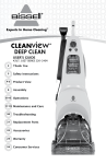
Drive Information
Table 3
MOTOR HP
(ESP)
MODEL NO.
RPM
(ESP)
MOTOR
PULLEY
CFM
0.5"
1.0"
0.5"
1.0"
0.5"
1.0"
DRY-10 SERIES
900
1/3
1/3
555
980
VL34
VL44
DRY-20 SERIES
1400
1/2
1/2
759
1060
VL34
VL44
DRY-30 SERIES
2200
1
1
624
920
VL44
VL44
DRY-40 SERIES
3200
1-1/2
630
710
VL44
VL44
DRY-50 SERIES
5200
3
959
1070
1-1/2
3
1VP-50-7/8
All DryAire dehumidifiers are shipped from the factory with the external static pressure set at 0.50" ESP.
Units can be special ordered adjusted to 1.0" ESP direct from the factory or field adjusted as above.
5.4.
Pulley Adjustment
If ESP readings indicate low air flow, loosen set screw on the variable pitch motor
pulley and turn outer face clockwise. On higher than required air flow, then turn the
outer pulley face counter-clockwise.
IMPORTANT: Be sure to re-tighten the set screw on the flat spot of the pulley hub.
If you have any questions concerning blower speed, cfm, or static pressure field
adjustment, contact factory.
25
DryAire Systems
6.0.
Start-Up Procedure
A complete start-up will minimize problems and expensive callbacks. The start-up will be quicker
and easier if the space to be dehumidified is at its design temperature and humidity condition. You
may need to use portable heaters to heat the room. Read this section thoroughly before attempting
to start-up the DryAire dehumidifier.
6.1.
Prior to Start-Up
IMPORTANT: THE MAIN POWER TO THE UNIT CRANKCASE HEATER MUST BE ON
FOR A MINIMUM OF 24 HOURS BEFORE UNIT IS OPERATED.
7.0.
1.
LEAK TEST ALL FIELD AND FACTORY PIPING.
2.
Check the rating plate for power requirements. The available power supply voltage
must be within + 10% of the voltage printed on the rating plate.
3.
Verify that all field wiring matches the DryAire wiring schematics and inspect and
tighten all field and factory wiring.
4.
Check and adjust the belt tension for 1” deflection at the mid-point of the blower
belt(s). Check and make sure set screws on pulleys are tight and secure.
5.
Check the drain pan and the condensate piping by pouring water into the drain pan
to prime the P-trap assembly. Inspect for leaks.
6.
If you installed a supplemental or auxiliary air heater, make sure it is installed in the
air discharge (supply) duct and not the return duct.
7.
If you installed an outdoor remote condenser verify that all service valves in the
dehumidifier refrigerant lines are fully open and the jumper wire has been added to
the thermostat sub-base as indicated on the control wire diagram.
8.
Inspect the air filters and coils for dirt or construction debris. If necessary, clean the
coils and install new air filters.
9.
Make sure that neoprene vibration isolator pads are placed under the dehumidifier
at each corner and unit is level.
Operational Sequence
The standard operating modes for a DryAire dehumidifier with a remote outdoor condenser
is very simple. When ever the compressor is running, R-22 refrigerant flows through the
evaporator coil and absorbs heat from the warm, humid return air. This heat must be rejected to either the swimming pool room or the remote outdoor condenser. The dehumidifier will
direct the heat where it is needed (or not needed) as determined by the control set-points.
Whenever a remote outdoor condenser is not used in the system, the dehumidifier will
always reject the heat to the swimming pool room. In warmer months, if room temperature
exceeds 95°F to 100°F, the safety high pressure switch will shut the compressor down
to protect the compressor. Should the safety switch continue to trip out from high head
pressure, you may want to add the optional remote outdoor condenser previously offered.
DryAire Systems
26
REFRIGERATION FLOW DIAGRAM
DEHUMIDIFIER ONLY
[Fig. 1]
The DryAire dehumidifier installed by itself will always
discharge warm dry air back to the room. The discharge air temperature will be approximately 10°F to
20°F above the inlet air temperature. The moisture
content of the air will also contribute to the temperature rise.
If the discharge of warm supply air becomes a concern, especially during summer months, we recommend an optional Remote Outdoor Condenser that
properly matches the system.
REMOTE OUTDOOR
AIR-COOLED CONDENSER [Fig. 2-3]
The addition of a DryAire remote outdoor condenser
will transform the dehumidifier into an air conditioner
and allow cool dry air to discharge back into the
room. The cool dry discharge air temp will be approximately 10°F to 20°F below the inlet air temperature.
This function is controlled by an automatic change
over thermostat.
SYSTEM DESIGN
When the DryAire de-humidistat control calls for
dehumidification, the thermostat monitors the room
temperature; if the temperature is above the setpoint, the changeover thermostat will automatically
switch to cooling mode.
An electronically operated solenoid valve will divert
the flow of refrigerant from the internal condenser in
the dehumidifier to the outdoor remote condenser,
allowing the dehumidifier to discharge cool dry air
into the room.
When the thermostat is satisfied and the room temperature falls below the heating setpoint, the thermostat will automatically call for heat and the solenoid
valve will divert the refrigerant back to the internal
condenser located in the dehumidifier and discharge
warm dry air.
27
DryAire Systems
7.1.
System Modes of Operation
7.1.1.
Dehumidification / Air Reheat Mode
When the room air requires dehumidification and heating, the dehumidifier runs
in the “reheat” mode. The hot refrigerant is discharged into the reheat condenser,
which warms the dry air. The air that is discharged as supply air from the unit is
drier and approximately 15°F to 20°F warmer than the entering return air.
7.1.2.
Dehumidification / Air Cooling Mode
When the room air requires cooling or dehumidification and cooling, the dehumidifier
will run in the air cooling mode. The hot refrigerant must be discharged to a remote
condenser other than the reheat coil. The hot refrigerant can be discharged to an
outdoor remote condenser, if so equipped. The air that is discharged as supply air
from the dehumidifier is drier and approximately 20°F cooler than the entering return air.
7.1.3.
Blower Operation
When the fan on the automatic change-over thermostat is set in the “auto”
position, the blower motor will start on a call for dehumidification, heating or cooling,
(outdoor remote condenser required for cooling mode). As the controls become
satisfied, the blower motor will shut off.
When the fan on the automatic change-over thermostat is set in the “on” position, the
blower motor will run continuously. This helps prevent air stagnation and stratification.
Note: If duct sensors are used to read the temperature and humidity levels, then
the blower must also operate continuously to provide proper air movement over the
duct sensors.
7.2.
Power On !
7.2.1.
Set the de-humidistat control below the room condition, the dehumidifier should start
and operate normally. If dehumidifier does not start, check the electrical connections.
7.2.2.
Measure the outlet air and the inlet air temperatures. The air leaving the dehumidifier
should be approximately 15°F to 20°F (plus or minus 2°F) warmer than the entering
air temperature.
NOTE: When a dehumidifier is installed with a remote outdoor condenser the air
temperature leaving the dehumidifier should be approximately 15°F to 20°F (plus or
minus 2°F) cooler than the entering air temperature.
DryAire Systems
28
Thermostat Set-Points
8.0.
7.2.3.
The Honeywell® automatic change-over t-stat has a minimum 3°F dead band.
Setpoint require 2°F for heat and 2°F for cool. For a desired temperature
of 82°F room, set heat at 80°F and cool lever at 84°F.
7.2.4.
At this time, the blower should be checked for correct rotation and the adjustable
motor pulley set for the proper air delivery. Make proper adjustments to the pulley
and / or the motor mounting bracket if necessary for design air quantity.
7.2.5.
Check the refrigerant pressures, the head pressure should be 180 / 275 psi
suction pressure should be 50 / 65 psi, depending on current load conditions.
Start-Up Report Procedure
8.1.
The start-up report is located in the installation and operational manual envelope that came
with the equipment. An additional copy for your review is also located in this manual. Read
and fill out the report completely. Upon receipt of this report, DryAire will verify the integrity
of the installation. A thorough start-up can reduce callbacks and help increase customer
satisfaction. Be sure to keep a copy for future reference. If the start-up report is misplaced,
call DryAire Systems for a new copy.
THE START-UP REPORT IS REQUIRED FOR WARRANTY VALIDATION AND REGISTRATION #.
9.0.
8.1.1.
Record the return air temperature and suction line pressure, condenser and supply
air discharge on start-up report provided.
8.1.2.
At this time check the actual amp rating of the equipment.
8.1.3.
Return the de-humidistat to the normal setting, usually its between 50% and 60%
relative humidity.
Maintenance Procedure
Only minimal maintenance is required of the DryAire dehumidifier. The compressor and
refrigeration circuit is a sealed system and repairs must only be made by qualified service
technicians.
9.1.
29
Monthly Inspection
1.
Air filters should be inspected and replaced if necessary.
2.
Check the air flow around the outdoor remote condenser to make sure the intake
and discharge grilles are obstruction free form leaves or snow build-up.
DryAire Systems
9.2.
Six Month Inspection
WITH POWER SUPPLY OFF!
1.
Check the blower belts in the dehumidifier and the optional remote outdoor
condenser for excessive wear, cracks and proper tension. Approximately 1”
deflection at their midpoint.
2.
Check and tighten, if needed, all electrical connections.
3.
Inspect the condensate drain pan and clean if necessary.
4.
Check both refrigerant pressures and amp draw on motors and compressor.
Compare the readings with the original copy of the start-up report.
10.0. Trouble Shooting Section
10.1.
10.2.
Unit Will Not Operate
De-humidistat set too high.
Lower de-humidistat setting until unit comes on.
Thermostat switch set in off mode.
Set thermostat to automatic mode.
No main power.
Re-set circuit breaker.
Controls stuck in open position.
Repair or replace control.
Condensation on Walls
De-humidistat turned off.
Turn de-humidistat on to desired setting.
Air and pool water temperature
imbalance.
Air temperature should be 2°F above the water
temperature. Recommended at 82°F air temp.
and 80°F water temp. for best efficiency.
Air stratification.
Consider continuous blower operation.
Blower running to fast.
Adjust blower speed.
Location of sensor controls.
Change location of controls.
Ductwork design.
Refer to catalog data sheets.
Poor air distribution.
Evaluate duct design and dehumidifier location.
DryAire Systems
30
10.3.
10.4.
Evaporator Coil Freeze Up
Entering air temperature too low.
Raise entering air temperature.
Insufficient evaporator air flow.
Check system air flow, dirty filters/coils or restricted
ductwork.
Lack of refrigerant.
Check suction pressure and evaluate unit charge.
Restriction in filter dryer.
Check pressure drop and replace if necessary.
Restriction in refrigerant piping.
Evaluate debris in distributor.
Defective expansion valve.
Check expansion valve performance and replace
if necessary.
Faulty or improperly set hot-gas
bypass valve.
Open hot-gas isolation valve, if equipped. Set hot
gas valve to maintain 32°F suction temperature
(58 psig), or replace if necessary.
Head Pressure Too High / In Cooling Mode
The outdoor remote condenser can cause high head pressures.
Lack of air flow.
Check remote outdoor condenser coil for debris.
Remote condenser blower motor
A. Overload tripped out.
Reduce blower speed and reset overload.
B. Blower cycling on internal protection. Reduce blower speed.
Note:
31
C. Contactor faulty.
Replace contactor.
D. Jumper wire missing on sub-base.
Add jumper wire, refer to wire diagram.
Service valves not fully open.
Fully open service valves.
Excessive pressure drop in line sets.
Re-evaluate remote condenser installation section.
When the outdoor remote condenser is active and the outdoor temperature is 95°F,
the normal head pressure can be as high as 300 psig.
DryAire Systems
11.0. Service Diagnosis Chart
11.1.
Dehumidifier Runs
DEHUMIDIFIER RUNS
LOW HEAD
HIGH SUCTION
• Defective valve(s)
in compressor.
HIGH HEAD
PRESSURE
•
•
•
•
•
•
•
•
LOW SUCTION
PRESSURE
Loose belt or pulley.
Not enough air.
Air short cycling.
Dirty coil.
Air in system.
Refrigerant over charged.
Ball valve closed.
Return air temperature
above 90°F.
•
•
•
•
•
•
Low on refrigerant.
Not enough air.
Restricted distribution.
Dryer restricted.
Bad TXV valve.
Power element.
DEHUMIDIFIER OFF {CONTACTOR OPEN}
HOLDING COIL IS POWERED
• Burned out holding coil.
NO POWER AT HOLDING COIL
•
•
•
•
•
•
•
Control wire loose or broken.
Compressor internal wire open.
High pressure switch open.
Low pressure switch open.
Compressor internal overload.
Transformer or time delay open.
De-humidistat control set above
room condition.
NOTE: Minimum Operating Pressures
SUCTION PRESSURE 48 psi
HEAD PRESSURE 180 psi
DryAire Systems
32
11.2.
Dehumidifier Off
DEHUMIDIFIER OFF
{CONTACTOR CLOSED}
COMPRESSOR HUMS
•
•
•
•
DOES NOT HUM
Refrigerant pressure not equalized.
Run capacitor open.
Compressor wiring open.
Three phase compressor stuck
on single phasing.
• Contactor points burned.
• Compressor wiring open.
• Thermal overload open.
DEHUMIDIFIER SHORT CYCLES
LOW PRESSURE
CONTROL
•
•
•
•
Low charge.
• Low suction pressure.
DX valve power element. • Suction too warm.
Dryer restricted.
Low air flow.
HI-PRESS SWITCH
TRIPPING / REPEAT
• Dirty filter.
• Slow blower speed.
• Room temperature too
high.
• Supply or return air
grilles restricted.
• Defective high pressure
switch.
33
COMPRESSOR
THERMOSTAT
HI-PRESS SWITCH
TRIPPING / REPEAT
•
•
•
•
•
•
THERMAL
OVERLOAD
Normal Suction
• Low voltage.
• Unbalanced phase.
• Tight compressor.
High Suction
• Bad compressor.
• Blower set for too
much air flow.
Over-charged.
Air in system.
Dirty filter.
Short cycling air.
Low air flow.
Return air temperature
above 90°F.
DryAire Systems
12.0. Unit Operating Guidelines
12.1.
Controller Set-Points
It is important to determine your comfortable set points and to avoid further controller
adjustments. It takes time for the unit to establish equilibrium at a given set point.
Therefore, continued set point adjustments will lead to high energy cost and user
discomfort. Continuous blower operation is recommended. This will reduce air
stratification and assure that the refrigeration circuit is activated only when necessary.
Recommended Set-Points:
A.
Humidity 50% to 60% RH.
B.
Air temperature 2°F - 3°F above pool water temperature, but not to exceed 86°F.
Warning:
12.2.
Never disable a dehumidifier in a pool room application unless the pool has been
drained. Even when not in use, pool water continues to evaporate adding moisture
to the air. The high humidity moisture will seep into walls, ceilings and furniture.
The dehumidifier may be capable of regaining control of the pool room conditions
after re-start, however the moisture damage to the room will become apparent.
Refrigeration Pressures
Many load factors affect the refrigeration pressures on a given day. Such factors include
ambient temperature, water temperature, relative humidity and air flow. However, for the
sake of trouble shooting, note the following:
A.
Normal suction pressure range: 48 to 70 psig.
B.
Normal head pressure range:
Note:
12.3.
Always check the system air flow before trouble shooting the refrigeration circuit.
Temperature Rise / Drop Across Unit
A.
Typical air temperature rise across unit in Reheat mode: 10°F - 20°F.
B.
Typical air temperature drop across unit in A/C mode: 10°F - 20°F.
Note:
12.4.
180 to 275 psig.
If your unit does not meet these temperature ranges, check the system air flow.
Pool Water Chemistry
Pool chemistry must be maintained to ensure the proper pH, total alkalinity calcium
hardness and free chlorine. NSPI recommends the following levels for pool chemistry:
Free Chlorine 1.0-3.0 ppm
pH 7.4 - 7.6
Total Alkalinity 100-150 ppm
Calcium Hardness 200-250 ppm
DO NOT STORE CHEMICALS IN THE SAME ROOM AS THE DEHUMIDIFIER!
Service Problems Caused By Excessive Chemical Levels Are Not Covered Under Warranty.
DryAire Systems
34
13.0. SMACNA Duct Designs
When the DryAire dehumidifier is to be installed with a ducted air supply, close attention
must be made SMACNA low velocity duct construction standards. Undersized or restrictive
ducts reduce the system airflow, which can cause premature compressor failure. Refer to
this diagram when designing ducts.
Recommended!
Not Recommended!
20° or Less
30° or More
Discharge
Discharge
Turn
Vanes
DryAire
DryAire
W
5W or More For
Static Pressure Regain
Intake
Intake
Turn
Vanes
DryAire
W
DryAire
2.5W or More
Intake
Intake
Turn
Vanes
DryAire
DryAire
Figure 11. Recommended Duct Designs For DryAire Dehumidifiers
35
DryAire Systems
14.0. Outside Air Pre-Heating Requirements
DryAire Systems require that outside air be pre-heated if mixed air temperatures inside the
dehumidifier might fall below 45°F. To determine if an application requires pre-heating of
outside air, follow simple guide.
14.1.
14.2.
Data required:
A.
Design return air temperature. (Industry standard is 82F.)
B.
Outside air at winter design temperature. Use values as specified by
design engineer, architect, or ASHRAE tables.
C.
Total system CFM (dehumidifier unit) and required outside air CFM.
Determine worst case scenario for Mixed Air Temperature using the following equation:
MAT=(winter temp °F) x (OA CFM) + (return air temp °F) x (system CFM - OA CFM)
(system CFM)
(system CFM)
14.3.
If Mixed Air Temperature is less than 45°F, then the pre-heating of outside air is required.
Note:
14.4.
Outside air duct must be insulated to prevent condensation which may form
on the exterior of the duct during cold winter months.
Example:
DRY-30-230-1 dehumidifier (2200 system CFM)
Pool Room Project, 400 CFM of outside Air.
Location, St. Paul, MN. winter temperature condition -16°F.
MAT = (-16°F) x 400 cfm + 82°F x (2200 unit cfm - 400 cfm) = 64.1°F.
2200 cfm
2200 cfm
Conclusion: No need to pre-heat outside air cfm.
15.0. Compressor Failure
Some compressors fail because they are mechanically flawed, most failures are due to system
related problems. Compressor failure can be caused by air or moisture in the refrigerant system,
solid contaminant’s, excessive heat liquid flood back or electrical service malfunctions. To avoid
repeated callbacks, you must determine the cause of the failure and then correct it.
If the compressor failed because its motor has burned out, the refrigerant, oil, and piping may have
become severely contaminated. If a burnout has occurred, use the following procedure to replace
the compressor and clean the refrigerant system.
DryAire Systems
36
YOU MUST CLEAN THE SYSTEM THOROUGHLY TO PREVENT REPEATED COMPRESSOR
BURNOUTS!
15.1.
Mild Burnouts (use new R-22)
If the burnout is mild, recover the refrigerant charge.
Replace the suction filter with a suction line filter-drier. Sporlan manufactures a special
“HH” filter-dryer for cleaning system burnouts. These filters are equipped with a tap for
measuring the pressure drop across the filter. Remove the old liquid line filter-drier and
replace it with a new “HH” type filter one size larger than the original. Remove the old
compressor if you have not already done so.
Install the new compressor. Be careful not to overheat its pipe stubs. Evacuate the system
to remove the moisture and non-condensables from the refrigeration circuit. Check piping
and joints for leaks, and recharge the system with new refrigerant.
Note:
15.2.
`
The R-22 refrigerant charge must be accurately weighed back into equipment.
Refer to charging charts in this manual.
Severe Burnouts (use new R-22)
If the burnout is severe, recover the refrigerant charge. You may need to energize the
liquid line solenoid valve to evacuate the circuit completely.
Verify that the TXV and solenoid valves are not plugged with debris. Clean or replace them
if necessary. Replace the suction filter with a suction line filter-drier. Sporlan manufactures
a special “HH” filter-driers for cleaning system burnouts. These filters are equipped with a
tap for measuring the pressure drop across the filter. Remove the old liquid line filter-drier
and replace it with a new “HH” type filter one size larger than the original. Remove the old
compressor if you have not already done so.
Install the new compressor. Be careful not to overheat its pipe stub. Evacuate the system
to purge the moisture and non-condensables from it. Check the compressor contactor for
damage or pitted contacts. Some compressors are equipped with start capacitors, run
capacitors, and starting relays. Check these components and replace them if necessary.
Check the piping and joints for leaks, and recharge the system with new refrigerant. Run the
refrigeration system for an hour while you monitor the pressure drop across the suction filter.
If the pressure drop is 3 psig or less after one hour continue to run the system for 24 hours,
then take an oil sample.
If the oil sample is dirty or acidic,or if the one-hour pressure drop is greater than 3 psi, then
recover the system charge and replace both the suction and liquid filter-dryers. Repeat the
previous step until your oil sample tests negative.
Note:
37
The R-22 refrigerant charge must be accurately weighed back into equipment.
Refer to charging Table 4, 5 Page 38.
DryAire Systems
16.0. Refrigerant Charts
Table 4.
DryAire
Model No.
DRY-10
DRY-20
DRY-25
DRY-30
DRY-40
DRY-50
Factory
Charge
R-22
SERIES
SERIES
SERIES
SERIES
SERIES
SERIES
11#
12#
17#
19#
35#
65#
Table 5.
MODEL
OC-10
OC-20
OC-25
OC-30
OC-35
OC-40
OC-45
OC-50
SERIES
SERIES
SERIES
SERIES
SERIES
SERIES
SERIES
SERIES
(UP TO 25') (26' TO 50')
12#
15#
23#
23#
36#
36#
37#
51#
14#
18#
28#
28#
40#
40#
41#
57#
NOTE: THIS CHARGE IS IN ADDITION TO THE
DRYAIRE DEHUMIDIFIER UNIT. CHARGE
MUST BE WEIGHED INTO SYSTEM
Example:
DRY-30 Series dehumidifier
19#
19#
OC-30 Series outdoor remote condenser
Up to 25’ of line set
23#
26’ to maximum 50’
Total R-22 Charge
DryAire Systems
28#
42#
47#
38
17.0. Start-Up Report
Start-up Report
DRY-SERIES Dehumidification Systems Equipment
W185 N11497 WHITNEY DRIVE
GERMANTOWN, WI 53022
262/250-8500
FAX 262/250-0886
[email protected]
In order for warranty to be valid, a start-up report must be completed and returned to the factory.
If the report is not sent back, warranty will be voided on the equipment.
Installation Name..............................................................................................................................
Installation Address...........................................................................................................................
City/State/Zip.....................................................................................................................................
Model # .................................................................................... Serial # ..........................................
Compressor Serial # ................................................................ T-Stat # ...........................................
Electrical Power Source
208/230V-1O
208/230V-3O
Reading
460-3O
Nameplate
Blower Voltage
Blower Amperage
Compressor Voltage
Compressor Amperage
Operational Data
Note: To obtain adequate readings, the room temperature must be at design condition or a
minimum of 80°F and a delay of ten [10] minutes is required between every mode of
operation and adjustment.
Reheat Mode
Entering Air Temperature
°F
Leaving Air Temperature
°F
Head Pressure
PSIG
Suction Pressure
PSIG
Room Temp:________°F.
Pool Water Temp:________°F.
Charged Outdoor Condenser R-22
Company Name
Email
#
Cooling Mode
Duct Heater Installed:________Y/N
Pipe length from dehumidifier to condenser.
Completed by
Phone #
Date
W185 N11497 WHITNEY DRIVE GERMANTOWN, WI 53022
(262) 250-8500 FAX (262) 250-0886 eMAIL [email protected]