1
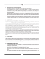
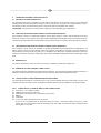
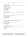
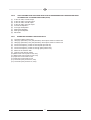
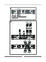
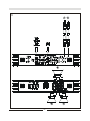
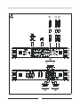
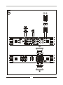
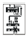
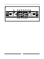
GB
Dear MAGNAT Customer,
The RX 44 car hi-fi power amplifier will enable you to satisfy your high demands on sound reproduction in your
car. With its impressive deep-bass power reserves, low harmonic content and neutral reproduction, the RX 44
takes car hi-fi to new heights. The amplifier is characterized by low operating current, rapid switching capabilities
and excellent temperature stability. Experience and enjoy how this high-tech machine perfectly reproduces
magnificent sound.
Please read all of the owner’s manual before installing and using the amplifier.
1.
TECHNICAL DATA
RX 44
Stereo
Max. output power (1 kHz sinus burst 2:8, B+=14.4V)
Nominal output power (DIN 45 342, B+=14.4V)
Max. output power (1 kHz sinus burst 2:8, B+=14.4V)
Nominal output power (DIN 45 342, B+=14.4V)
Loudspeaker impedance (stereo)
Frequency response
Total harmonic content (DIN 45 403)
Stereo separation (IEC 581 )
Weighted noise distance (IEC A)
Input sensitivity LOW LEVEL INPUT
Input impedance LOW LEVEL INPUT
Low-pass filter
High-pass filter
Bass boost
Subsonic filter
Supply
Fuse
Sizes (W x H x D)
Weight
/ Bridged
2 x 250 W / 1 x 650 W on 4 Ohm
2 x 125 W / 1 x 325 W on 4 Ohm
2 x 320 W
on 2 Ohm
2 x 160 W
on 2 Ohm
2 – 8 Ohm
5 – 50 000 Hz (-3 dB)
< 0.05 % (1 kHz)
> 60 dB (1 kHz)
> 100 dB
0.4 – 4 V
20 kOhm
40 – 300 Hz, 12 dB per octave
40 – 300 Hz, 12 dB per octave
0…15 dB at 45 Hz
15 Hz, 12 dB per octave (channel 3 and 4 only)
+12 V (9 – 15 V), minus to ground
2 x 40 A
350 x 50 x 261 mm
4.1 kg
SUBJECT TO TECHNICAL CHANGE
2.
FEATURES
·
·
·
·
·
·
·
·
·
·
·
·
·
·
·
·
Complementary push-pull final stage
Automatic switching on/off via car radio
Infinitely adjustable low-pass filter 40 – 300 Hz
Infinitely adjustable high-pass filter 40 – 300 Hz
Infinitely variable bass equalisation
Subsonic filter 15 Hz (channel 3 and 4 only)
Adjustable input sensitivity
Bridgeable 4-/3-/2-channel mode
Tri-mode
Channel mode selector switch
Electronic protective circuit against short circuiting, DC offset and excess temperature
Mute switch for suppressing switch-on crackle interference
Capsulated loudspeaker and power-supply screw terminals
Low-level outputs (cinch jacks) for connecting additional amplifiers (channel 3 and 4 only)
Status indicator (green LED) and overload indicator (red LED)
Harmonic distortion spectrum
9
GB
3.
IMPORTANT INSTALLATION INFORMATION
·
·
This appliance may only be connected to a 12 volt system with negative ground.
The heat radiated when the amplifier is used means that sufficient air circulation is required at the place
of installation. It is very important that the cooler’s cooler ribs do not contact any metal plating or any
surfaces which could impair air circulation. The amplifier may not be installed in small confined spaces or
spaces without air circulation (e.g. spare wheel recess or under the vehicle carpeting). Installation in the
boot is recommended.
Install the amplifier in such a way that it is protected as far as possible against vibrations and dust and dirt.
Make sure that the input/output cables are sufficiently distant from the power supply cables as otherwise
interference may occur.
Make sure that the fuse and operating elements are accessible after installation.
The appliance’s reliability and performance depend on the quality of installation. Preferably get an expert
to install the system, particularly if you want to install several loudspeakers or a complex multi-way system.
·
·
·
·
4.
CONNECTIONS
4.1 POWER SUPPLY AND AUTOMATIC SWITCHING ON
Important notice: Before commencing the installation, disconnect the plus terminals from the car
battery in order to prevent short circuits.
The power cabling usually installed in on-board car networks is not sufficient for a power amplifier’s demands.
Make sure that the power lines to GND and to the +12 V terminal have been sufficiently specified. A cable crosssection of at least 16 mm² must be used to connect the battery to the amplifier’s terminals.
First connect the amplifier’s GND terminal to the battery’s minus pole. It is very important that the connection
is good. Dirt residues must be carefully removed from the battery’s connection point. A loose connection may
cause malfunctions or interference noise or distortion.
The +12 V amplifier connection must then be connected with a power cable possessing an integrated fuse to
the battery’s plus pole. The fuse must be located close to the battery, the length of cable from the battery’s
positive pole to the fuse must be less than 60 centimetres for safety reasons. Only insert the fuse when all
installation work, including the connection of the loudspeakers, has been completed.
Now connect the car hi-fi receiver’s remote control connection to the amplifier’s REM control jack. A cable with
a cross-section of 0.75 mm² is sufficient for connecting the amplifier’s REMOTE connection and the control
device.
4.2 AUDIO CABLES
When installing the audio cable between the cinch output of your car receiver and the cinch input of the amplifier
inside your car, the audio and power supply cables should, wherever possible, not be routed along the same
side of the vehicle. We recommend an isolated installation, e.g. routing the power cable through the cable duct
on the left-hand side and the audio cable through the cable duct on the right-hand side or vice versa. This
reduces interference due to crosstalk into the audio cables.
4.3 LOUDSPEAKER CONNECTIONS
·
·
·
·
·
In normal operating mode (i.e. one loudspeaker on each individual amplifier channel), the lowest terminal
resistance is 2 ohm per channel.
In bridging mode (two amplifier outputs combined) the lowest terminal resistance doubles to 4 ohm.
The impedance in tri-mode may not fall below 2 ohm per channel.
Never connect the loudspeakers’ minus terminals to the vehicle chassis.
Never connect the +12 V supply voltage to a loudspeaker output as this would destroy the amplifier final
stage.
If the amplifier is operated with lower terminal resistances or incorrectly used as described above, both
the amplifier and the loudspeakers may be damaged. The warranty becomes void in such cases.
10
GB
5.
OPERATING ELEMENTS AND IN/OUTPUTS
5.1 SETTING THE INPUT SENSITIVITY
The input sensitivity may be adapted to any car radio or tape deck. Turn the volume control of your radio to its
central position and then adjust the input-level controls (12) and (13) to produce an average medium volume.
This setting usually provides sufficient power reserves at optimum weighted noise voltage.
ATTENTION: only reproduce loud test noises briefly to prevent damaging the loudspeakers.
5.2 LOW-PASS FILTER WITH ADJUSTABLE CROSS-OVER FREQUENCY
If the amplifier is used as a subwoofer amplifier, set the switch (2)/(3) to “LOW”. Set the desired cross-over
frequency using the control (4)/(5). This makes the filter adaptable to the installed woofer’s sound requirements.
The filter’s high edge steepness is responsible for the precision reduction of medium and high frequency ranges.
5.3 HIGH-PASS FILTER WITH ADJUSTABLE CROSS-OVER FREQUENCY
If the amplifier is to be used as an amplifier for satellite loudspeakers (mid-range/tweeter loudspeakers), set
switch (2)/(3) to “HIGH”. Set the desired cross-over frequency using the control (6)/(7). Only the frequencies
above the set cross-over frequency will then be amplified. This effectively minimizes distortions caused by
excessive membrane movement at low frequencies and small satellite loudspeakers without reducing the bass
level.
5.4 BASS-BOOST
The bass-boost function (10/11) is used to increase or equalize the lower bass frequencies.
5.5 SUBSONIC FILTER (CHANNEL 3 AND 4 ONLY)
The subsonic filter (8) attenuates the lowest bass frequencies. This arrangement allows efficient prevention of
distortion caused by excessive membrane excursions without affecting the useable bass level.
5.6 OUTPUTS FOR CONNECTING ADDITIONAL AMPLIFIERS
The input signal of the INPUT connections CH3 / CH4 (14) is forwarded directly to the OUTPUT (1) jacks. The
OUTPUT connections allow the use of additional amplifiers without requiring additional T-plugs and cables.
FIG. 1 POWER SUPPLY / REMOTE SWITCH-ON CONNECTIONS
(1)
(2)
(3)
(4)
(5)
(6)
Terminal for +12 V battery voltage
REM terminal for remote switch-on
GND terminal for the ground, to the battery’s minus pole
Battery
Cable fuse
To your car radio’s automatic aerial connection
If your car is not equipped with an automatic aerial connection, connect this cable’s plus pole (+) to the
ignition lock. An on/off switch should be inserted in this case. Make sure that this switch is switched off if
the amplifier is not used.
11
GB
FIG. 2
4-CHANNEL MODE
Connect and set the amplifier as shown in Fig. 2 if it is to be controlled by a car radio with four output channels
and used with four loudspeakers:
(1)
(2)
(3)
(4)
(5)
(6)
(7)
(8)
To the car radio, front left output
To the car radio, front right output
To the car radio, rear left output
To the car radio, rear right output
Front left loudspeaker
Front right loudspeaker
Rear left loudspeaker
Rear right loudspeaker
FIG. 3/4 3-CHANNEL MODE
The 3-channel mode uses the high-pass filter for channels 1/2 and the low-pass filter for Channels 3/4. Section
5 describes how they are used.
FIG. 3
Connect and set the amplifier as shown in Fig. 3 if it is to be controlled by a car radio with stereo output and
used with stereo satellite loudspeakers and a subwoofer.
(1)
(2)
(3)
(4)
(5)
To the car radio, left output
To the car radio, right output
Left satellite loudspeaker
Right satellite loudspeaker
Subwoofer
FIG. 4
Connect and set the amplifier as shown in Fig. 4 if it is to be controlled by a car radio with stereo receiver and
separate subwoofer output and used with stereo satellite loudspeakers and a subwoofer.
(1)
(2)
(3)
(4)
(5)
(6)
To the car radio, left output
To the car radio, right output
To the car radio, subwoofer output
Left satellite loudspeaker
Right satellite loudspeaker
Subwoofer
FIG. 5
2-CHANNEL MODE
If the amplifier has to generate more power to operate two subwoofers, connect and set it as shown in Fig. 5.
The use of the low-pass filter used is described in Chapter 5.
(1)
(2)
(3)
(4)
To the car radio, left output
To the car radio, right output
Subwoofer
Subwoofer
12
GB
FIG. 6
(1)
(2)
(3)
(4)
(5)
(6)
(7)
(8)
(9)
To the car radio, front left output
To the car radio, front right output
To the car radio, rear left output
To the car radio, rear right output
Front left loudspeaker
Front right loudspeaker
Rear left loudspeaker
Rear right loudspeaker
Subwoofer
FIG. 7
(1)
(2)
(3)
(4)
(5)
(6)
(7)
(8)
(9)
(10)
(11)
(12)
(13)
(14)
(15)
USE AS AN AMPLIFIER FOR FOUR SATELLITE LOUDSPEAKERS AND A SUBWOOFER USING
AN ADDITIONAL 2-CHANNEL AMPLIFIER (RX 22)
OPERATING ELEMENTS AND IN/OUTPUTS
Low level outputs (channel 3/4)
HPF (high-pass filter) / LPF (low-pass filter) / OFF option switch for channel 3/4
HPF (high-pass filter) / LPF (low-pass filter) / OFF option switch for channel 1/2
Cross-over frequency control for the low pass (channel 3/4)
Cross-over frequency control for the low pass (channel 1/2)
Cross-over frequency control for the high pass (channel 3/4)
Cross-over frequency control for the high pass (channel 1/2)
Switch for the subsonic filter
Channel mode selector switch
Bass-boost control (channel 3/4, rear)
Bass-boost control (channel 1/2, front)
Input-level control channel 3/4
Input-level control channel 1/2
Low-level inputs (channel 3/4, rear)
Low-level inputs (channel 1/2, front)
13
58
3
59
60
61
6
62
7
63