1
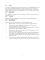
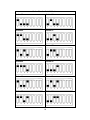
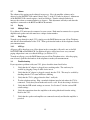
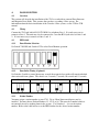
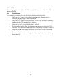
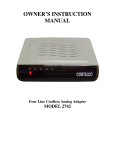
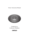
OWNER’S INSTRUCTION
MANUAL
Feature Module
MODEL 2743
Table of Contents
We want you to know all about your new Feature Module...........................................................4
IMPORTANT SAFETY INSTRUCTIONS..................................................................................5
1.
UNPACKING AND INSTALLATION ..........................................................................6
1.1
Box Contents.................................................................................................................6
1.2
Part Identification..........................................................................................................6
1.3
Overview ......................................................................................................................6
2.
MUSIC ON HOLD .......................................................................................................7
2.1
Overview ......................................................................................................................7
2.2
Phone Lines ..................................................................................................................7
2.3
DIP Switch....................................................................................................................7
2.4
Power............................................................................................................................7
2.5
Status Indicator .............................................................................................................7
2.6
Music Source ................................................................................................................7
2.6.1
Connection....................................................................................................................7
2.6.2
Device...........................................................................................................................7
2.6.3
Volume..........................................................................................................................8
2.6.4
Requirement..................................................................................................................8
2.6.5
Copyright ......................................................................................................................8
2.6.6
Troubleshooting ............................................................................................................8
3.
EXTERNAL PAGING ADAPTER................................................................................9
3.1
Overview ......................................................................................................................9
3.2
Wiring...........................................................................................................................9
3.2.1
Basic Wiring .................................................................................................................9
3.2.2
Wiring in Parallel ..........................................................................................................9
3.3
DIP Switch....................................................................................................................9
3.3.1
Paging Adapter Selection...............................................................................................9
3.3.2
All Page ........................................................................................................................9
3.3.3
Station Number .............................................................................................................9
3.4
Power.......................................................................................................................... 11
3.5
Status Indicator ........................................................................................................... 11
3.6
Amplifier Connection.................................................................................................. 11
3.7
Volume........................................................................................................................12
3.8
Paging .........................................................................................................................12
3.8.1
Multiple Units .............................................................................................................12
3.8.2
Single Page .................................................................................................................12
3.8.3
All Page ......................................................................................................................12
3.9
Troubleshooting ..........................................................................................................12
4.
DOOR MONITOR......................................................................................................13
4.1
Overview ....................................................................................................................13
4.2
Wiring.........................................................................................................................13
4.3
DIP Switch..................................................................................................................13
4.3.1
Door Monitor Selection...............................................................................................13
4.3.2
Door Strike Timing (Optional).....................................................................................13
4.3.3
Station Number ...........................................................................................................13
4.4
Power..........................................................................................................................14
4.5
Status Indicator ...........................................................................................................14
4.6
Door Intercom Connection ..........................................................................................14
4.7
Usage ..........................................................................................................................15
4.7.1
Door Intercom.............................................................................................................15
4.7.2
Door Intercom Volume ................................................................................................15
4.7.3
Magnetic Doorlock......................................................................................................15
4.7.3.1 Key Programming .......................................................................................................15
4.7.3.2 Doorlock Operation.......................................................Error! Bookmark not defined.
4.8
Troubleshooting ..........................................................................................................16
FCC INFORMATION...............................................................................................................17
TELEPHONE REPAIR .............................................................................................................18
LIMITED WARRANTY ...........................................................................................................19
THANK YOU
FOR PURCHASING THE
2743
Feature Module
We want you to know all about your new Feature Module.
To get the most from your Feature Module, please take time to read this guide thoroughly.
We have included information in your Owner’s Instruction Manual on how to install it, the
features it provides, and the services you can expect from its use.
The 2743 is one of Cortelco’s 7 Series 4-Line Telephone Units. It is part of a Four-Line system
consisting of up to 16 stations of 2740's, 2742's, 2743’s, or 2750's. The 2743 Feature Module
will allow Music on Hold, External Paging or a Door Intercom Adapter to be attached to your 4Line system.
Information on the other products in Cortelco’s 7 Series can be found on our website at
www.cortelco.com.
PLEASE READ BEFORE INSTALLING AND USING YOUR NEW
TELEPHONE EQUIPMENT.
IMPORTANT SAFETY INSTRUCTIONS
Always follow basic safety precautions when using your telephone equipment to reduce the
risk of fire, electrical shock, and injury.
1. Read and understand all instructions in the Owner’s Instruction Manual.
2. Read all warnings and follow all instructions marked on the product.
3. Unplug this product from the wall outlet before cleaning. Use a damp cloth for
cleaning. Do not use liquid or aerosol cleaners.
4. Do not use the 2743 Cordless Adapter near water. For example, do not use near a
bathtub, wash bowl, kitchen sink, laundry tub, swimming pool, or in a wet basement.
5. Do not place this product on an unstable cart or stand. The product may fall causing
serious damage to the product.
6. Do not place any objects on the telephone line cord. Do not locate the cordless adapter
where the line cords will be walked on.
7. Do not block or cover ventilation slots and openings in the top of the cordless adapter.
The openings should never be blocked by placing a book or paper on top of the adapter.
The adapter should never be placed near or over a radiator or heat register..
8. Never spill liquid on the cordless adapter or push objects of any kind through
ventilation slots. Liquid or objects may touch dangerous voltage points or short out parts
that could result in a risk of fire or electrical shock.
9. Do not disassemble this product. Opening or removing covers may expose you to
dangerous voltages or other risks. Incorrect reassembly can cause electrical shock when
the product is subsequently used.
10. Do not overload outlets and extension cords. Some telephones require AC power from
an outlet. Overloading the outlets can result in the risk of fire or electric shock.
11. Avoid using a telephone (other than a cordless type) during a local thunderstorm.
There may be a remote risk of electrical shock from lightning.
12. Use only the class 2 power transformer indicated in this manual.
13. Do not use a telephone to report a gas leak in the vicinity of the leak.
5
1.
UNPACKING AND INSTALLATION
1.1
Box Contents
The following items should be packed with your 2743. Please contact your dealer if any of them
is missing.
2743 Adapter (Main Body)
1 pcs
Line Cord 7ft
2 pcs
Power Adapter (Transformer 12VDC 500 ma)
1 pcs
Wiring Block
1 pcs
8-Wire Cord
1 pcs
Audio Cable
1 pcs
1.2
1.3
Part Identification
1
Input Jacks from wall
4
Paging Volume Control
7
Music Source Input
2
Output Jacks to phone
5
8-Wire Jack to Wiring
Block
8
Status Lamp
3
Music Volume Control
6
DIP Switch for Mode
Selection
9
Power Adapter Jack
Overview
Each 2743 module will allow ONE additional feature to be added to your Cortelco 4-Line
telephone system. The 2743 allows either Music on Hold, External Paging, or Door Monitor.
The function is selected by the DIP switch shown as Item 6 above.
Modules may be added to obtain additional features. For example, to provide Music on Hold
and External Paging to a system, two modules would be needed.
6
2.
MUSIC ON HOLD
2.1
Overview
This section will describe the installation of the 2743 to provide Music on Hold. This assumes
that you have a working 4-Line system. For information about the basic installation of the
Cortelco 4-Line system, see the 2740 or 2750 manual.
2.2
Phone Lines
Connect the 2743 jack labeled L1/L2 TO WALL to telephone Lines 1 and 2. This may be done
with one 4 wire line cord if the lines are wired to a two line RJ14 jack. If the lines are wired to
two single line RJ11 jacks a two-line coupler will be needed. Connect the 2743 jack labeled
L3/L4 TO WALL to telephone Lines 3 and 4.
2.3
DIP Switch
Set Switches 7 and 8 UP to activate Music on Hold.
2.4
Power
Connect the AC power adapter to the 12 VDC jack on the back of the 2743. This is shown as
Item 9 in the picture on Page 7. Plug the AC power adapter into a wall outlet. Please be sure this
outlet is not controlled by a switch.
2.5
Status Indicator
Verify that the status indicator (Item 8 Page 7) is blinking on and off rapidly. This shows that
power has been connected to the unit.
2.6
Music Source
2.6.1
Connection
Connect the music source to the Music Input Jack (Item 7 Page 7) using the audio cable supplied.
Note that the music source must have a 1/8 inch (3.5 mm) output jack. Plug one end of the cable
into the Music Input Jack on the 2743 and the other end into the output of the music source.
2.6.2
Device
Any music playback device (mp3 player, radio, tape player) with a 1/8 inch output jack may be
used as a music source. Also, cassette player with a continuous-loop tape may be used to
provide a personalized message instead of music.
7
2.6.3
Volume
The volume of the music on hold can be adjusted in two ways. First, the playback volume of the
music source can be adjusted, or the Music Vol. control (Item 3 Page 7) of the 2743 may be
adjusted. Adjustment of the Music Vol. control requires a small screwdriver. Turn the control
clockwise to increase the volume or counterclockwise to decrease. It is preferable to adjust the
volume at the music source.
2.6.4
Requirement
The 2743 requires a system of at least two 4-line telephones. Music will not be provided to a
single telephone system
2.6.5
Copyright
Please remember that it may be necessary to obtain a license when using equipment that
rebroadcasts copyrighted material.
2.6.6
Troubleshooting
If callers are not receiving music on hold, please check the following items.
1.
Remember that a system of at least two 4-line telephones is required for music.
2.
Verify that the AC adapter is plugged into a working outlet. The outlet may be
verified by plugging a lamp or other device into it.
3.
Verify that the AC adapter is plugged securely into the 2743. This may be verified by
checking that the 2743 status indicator is blinking.
4.
Check the volume. The volume may simply be too low for music to be heard. See
Section 2.6.3 for volume adjustment.
5.
Test the music source. Unplug the cable from the music input jack on the back of the
2743. Then place a call and place the caller on hold. The caller should now hear
music from the music IC of the 2743. If the caller hears music now, there is a problem
with the music source.
6.
Test the telephone wiring. Plug a standard telephone into the jack where the 2743 is
connected. Verify that you can make and receive a call. If not, the wiring is defective.
8
3.
EXTERNAL PAGING ADAPTER
3.1
Overview
This section will describe the installation of the 2743 to provide an External Paging Amplifier.
This assumes that you have a working 4-Line system. For information about the basic
installation of the Cortelco 4-Line system, see the 2740 or 2750 manual.
3.2
Wiring
3.2.1
Basic Wiring
Connect the 2743 jack labeled L1/L2 TO WALL to telephone Lines 1 and 2. This may be done
with one 4 wire line cord if the lines are wired to a two line RJ14 jack. If the lines are wired to
two single line RJ11 jacks a two-line coupler will be needed. Note that it is only necessary to
connect to Line 1 for proper operation.
3.2.2
Wiring in Parallel
It is possible to install your 2743 to a jack that is being used by another 4-Line telephone. To do
this, disconnect the other telephone from the wall and plug it into the jacks on the 2743 labeled
“TO PHONE.” Please be sure to connect the lines to the correct jacks. Then connect the 2743
jacks labeled “TO WALL” to the wall jacks. Again, please be sure to connect to the correct
jacks. Note that it is necessary to connect to all 4 lines to provide 4 line service to the connected
phone.
3.3
DIP Switch
3.3.1
Paging Adapter Selection
Set Switch 7 UP and Switch 8 down to select External Paging Adapter operation.
3.3.2
All Page
Switch 5 determines whether or not the 2743 will accept All Pages. Set Switch 5 Up to allow All
Pages. Set Switch Down to block All Pages.
3.3.3
Station Number
You must assign a station number to your 2743. You may use any number from 02 to 16. This
must be a number which is not currently in use by another phone in the system. Also, note that
the 2743 must NOT be set as Station 01. Use Switches 1 – 4 to set the station number. Refer to
the following pages to set the DIP Switches for the desired station number.
9
Station Number Switch Selection
Station 02
Station 03
Station 04
Station 05
Station 06
Station 07
Station 08
Station 09
Station 10
Station 11
Station 12
Station 13
10
Station Number Switch Selection
Station 14
Station 15
Station 16
3.4
Power
Connect the AC power adapter to the 12 VDC jack on the back of the 2743. This is shown as
Item 9 in the picture on Page 7. Plug the AC power adapter into a wall outlet. Please be sure this
outlet is not controlled by a switch.
3.5
Status Indicator
Verify that the status indicator (Item 8 Page 7) is blinking. For External Paging, the indicator
should blink twice rapidly every few seconds. This shows that power has been connected to the
unit.
3.6
Amplifier Connection
The 2743 connects to an external amplifier through the external wiring block and 8 wire modular
cord included with the unit. The external amplifier is then connected to the wiring block. The
steps for amplifier connection are as follows:
1.
Locate the 8 wire cord and the external wiring block. The 8 wire cord is black and is
approximately 6 inches long.
2.
Connect the cord to the jack on the back of the 2743 labeled “TO WIRING BLOCK.”
3.
Connect the other end of the cord to the wiring block.
4.
Install the amplifier and speaker by following the manufacturer’s directions.
Amplified speakers may also be used with the 2743. In this case no amplifier is
needed.
5.
Connect the amplifier input to the wiring block. If the amplifier input level is less than
-25 dBm, connect the amplifier to the BLUE and BLACK wires. If the amplifier input
level is greater than -25 dBm, connect the amplifier to the WHITE and BROWN
wires. No cables are included for this connection. They must be supplied by the user.
11
3.7
Volume
The volume of the paging can be adjusted in two ways. First, the amplifier volume can be
adjusted, or the PAGING VOL control (Item 4 Page 7) of the 2743 may be adjusted. Adjustment
of the PAGING VOL control requires a small screwdriver. Turn the control clockwise to
increase the volume or counterclockwise to decrease. This adjustment will only work when the
amplifier is connected to the BLUE and BLACK terminals.
3.8
Paging
3.8.1
Multiple Units
Up to fifteen 2743 units may be connected to your system. Each must be connected to a separate
amplifier and speaker and each must have a unique station number.
3.8.2
Single Page
To make a page through a single 2743, simply press the PAGE button on your 4-Line Telephone
and dial the extension number of the 2743. Then speak into the handset of the telephone to make
your announcement.
3.8.3
All Page
All pages will be heard on every 4-Line phone in the system that is idle and is not set for DO
NOT DISTURB or PAGE BLOCK. In addition all pages will be heard over every external
paging adapter that is not set to block All Page (see Section 3.3.2).
To make an all page, press the PAGE button on your 4-Line Telephone twice. After the paging
tone is heard, speak into the handset of the telephone to make your announcement.
3.9
Troubleshooting
If you experience problems with your 2743, please check the items listed below.
1.
Verify that the AC adapter is plugged into a working outlet. The outlet may be
verified by plugging a lamp or other device into it.
2.
Verify that the AC adapter is plugged securely into the 2743. This may be verified by
checking that the 2743 status indicator is blinking.
3.
Verify that the 2743 is plugged into the Line 1 wall jack.
4.
Test the telephone wiring. Plug a standard telephone into the jack where the 2743 is
connected. Verify that you can make and receive a call. If not, the wiring is defective.
5.
Verify that the DIP switch settings are correct. See Section 3.3 for the various DIP
switch settings.
6.
Verify the connections from the amplifier to the wiring block and from the wiring
block to the 2743.
7.
Verify that the speaker and amplifier are connected correctly and that the amplifier is
powered.
12
4.
DOOR MONITOR
4.1
Overview
This section will describe the installation of the 2743 to work with an external Door Intercom
and Magnetic Door Strike. This assumes that you have a working 4-Line system. For
information about the basic installation of the Cortelco 4-Line system, see the 2740 or 2750
manual.
4.2
Wiring
Connect the 2743 jack labeled L1/L2 TO WALL to telephone Line 1. It is only necessary to
connect to Line 1. The unit may also be connected to a two line RJ14 jack wired to Lines 1 and
2. It is not necessary to connect to Lines 3 and 4.
4.3
DIP Switch
4.3.1
Door Monitor Selection
Set Switch 7 DOWN and Switch 8 UP to select Door Monitor operation.
4.3.2
Door Strike Timing (Optional)
Set Switches 5 and 6 to control how many seconds the magnetic door strike will remain unlocked
when activated from a phone. The choices are 2 seconds, 5 seconds, 10 seconds and 15 seconds.
2 Seconds
5 Seconds
10 Seconds
15 Seconds
4.3.3
Station Number
You must assign a station number to your 2743. Up to 4 Door Intercom Adapters may be
installed. You may choose Station Numbers 13, 14, 15 or 16. This must be a number which is
not currently in use by another phone in the system. Use Switches 1 – 4 to set the station
number. Refer to the table below to set the DIP Switches for the desired station number.
13
4.4
Station 13
Station 14
Station 15
Station 16
Power
Connect the AC power adapter to the 12 VDC jack on the back of the 2743. This is shown as
Item 9 in the picture on Page 7. Plug the AC power adapter into a wall outlet. Please be sure this
outlet is not controlled by a switch.
4.5
Status Indicator
Verify that the status indicator (Item 8 Page 7) is blinking. For Door Intercom Adapter, the
indicator should blink slowly. This shows that power has been connected to the unit.
4.6
Door Intercom Connection
The 2743 connects to a Door Intercom through the external wiring block and 8 wire modular
cord included with the unit. The Door Intercom is then connected to the wiring block. The steps
for Door Intercom connection are as follows:
1.
Locate the 8 wire cord and the external wiring block. The 8 wire cord is black and is
approximately 6 inches long.
2.
Connect the cord to the jack on the back of the 2743 labeled “TO WIRING BLOCK.”
3.
Connect the other end of the cord to the wiring block.
4.
Install the Door Intercom and doorbell by following the manufacturer’s directions.
The 2743 is compatible with NuTone brand Door Intercoms although other brands
may also function correctly.
5.
Connect the speaker wires of the Door Intercom to the wiring block. Connect the +
speaker lead to the BROWN wire and connect the – speaker lead to the WHITE wire.
6.
Connect the doorbell wires to the wiring block. Connect one doorbell wire to the
BLUE wire and connect other doorbell wire to the GREY wire.
14
4.7
7.
OPTIONAL – Install the magnetic door strike by following the manufacturer’s
directions. The 2743 is compatible with most standard magnetic door strikes or
magnetic door locks. Please note that a 12 V power supply will be required for the
magnetic door strike to function. This must be supplied by the customer.
8.
OPTIONAL – Connect the magnetic door strike wires to the wiring block. Connect
one door strike wire to the GREEN wire on the wiring block. Connect the other door
strike wire to the 12V power supply. Connect the other terminal of the 12V power
supply to the YELLOW wire on the wiring block.
Usage
4.7.1
Door Intercom
When the button on the Door Speaker is pressed, that station number will appear in the displays
of all the phones in the system. To answer the door, press INTERCOM and then dial the station
number.
4.7.2
Door Intercom Volume
To adjust the volume of the door intercom bell, first press HOLD. Then press PAGE. Then
adjust the volume with the VOLUME button. Volume may be set separately at each phone. The
doorbell may also be set to OFF at any phone.
4.7.3
Magnetic Doorlock
4.7.3.1 Key Programming
The procedure to unlock a magnetic doorlock differs between the 2740 and 2750.
4.7.3.1.2 2740
For a 2740, you must first program a memory button to be a key. To program a button as a key
use the following instructions.
1. Press MENU. The display will read “Phone Setting.”
2. Press DOWN ARROW until “Memory Setting” appears in the display
3. Press ENTER. The display will read “Select Location
4. Press the Memory button where you wish to store the number. The display will show the
currently stored number, or indicate “Empty Location.”
5. Press the soft key under ENTER
6. Press FLASH
7. Press PAUSE
8. Dial the two digit extension of the 2743
9. Press the soft key under SAVE.
Once a key button has been programmed, the door may be unlocked simply by pressing that
button. It is not necessary to be connected to the Door Intercom at that time.
15
4.7.3.1.2 2750
To unlock a magnetic doorlock with the 2750, simply dial the extension number of the 2743 and
then press FLASH.
4.8
Troubleshooting
If you experience problems with your 2743, please check the items listed below.
1.
Verify that the AC adapter is plugged into a working outlet. The outlet may be
verified by plugging a lamp or other device into it.
2.
Verify that the AC adapter is plugged securely into the 2743. This may be verified by
checking that the 2743 status indicator is blinking.
3.
Verify that the 2743 is plugged into the Line 1 wall jack.
4.
Test the telephone wiring. Plug a standard telephone into the jack where the 2743 is
connected. Verify that you can make and receive a call. If not, the wiring is defective.
5.
Verify that the DIP switch settings are correct. See Section 4.3 for the various DIP
switch settings.
6.
Verify the connections from the door speaker to the wiring block and from the wiring
block to the 2743.
16
FCC INFORMATION
This equipment complies with Part 68 of the FCC rules. On the base of this equipment is a label that contains,
among other information, the FCC registration number and ringer equivalence number (REN) for this equipment. If
requested, this information must be provided to the telephone company.
The FCC requires that you connect your telephone to the telephone network through a modular telephone outlet or
jack, which must comply with FCC part 68 rules. The modular telephone outlet or jack to which your 2743 Cordless
Adapter must be connected is a USOC RJ11C or RJ14C. The Facility Interface code (FIC) for your 2743 Cordless
Adapter is 02LS2 which is a 2- wire, Local Switched Access, Loop-start.
The Ringer Equivalence Number (REN) is used to determine the quantity of devices which may be connected to the
telephone line. The REN for your 2743 Cordless Adapter is 0.1. Excessive RENs on the telephone line may result in
the devices not ringing in response to an incoming call. In most areas, the sum of the RENs should not exceed five
(5). To be certain of the number of devices that may be connected to the line, as determined by the total RENs,
contact the telephone company to determine the maximum REN for the calling area.
If the 2743 Cordless Adapter causes harm to the telephone network, the telephone company will notify you in
advance that temporary discontinuance of service may be required. If advance notice isn’t practical, the telephone
company will notify you as soon as possible. Also, you will be advised of your right to file a complaint with the
FCC if you believe it is necessary. The telephone company may make changes in its facilities, equipment, operations
or procedures that could affect the operation of the equipment. If this happens, the telephone company will provide
advance notice in order for you to make the necessary modifications in order to maintain uninterrupted service.
If trouble is experienced with your 2743 Cordless Adapter, please contact Cortelco Technical Support, 662-2875281 for repair and/or warranty information. If the trouble is causing harm to the telephone network, the telephone
company may request you remove the equipment from the network until the problem is resolved. Do not attempt to
repair or modify this equipment.
Please contact Cortelco for information on obtaining service for this product. This equipment cannot be used on
public coin service provided by the telephone company. Connection to Party Line Service is subject to state tariffs.
(Contact the state public utility commission, public service commission or corporation commission for information.)
This equipment is hearing-aid compatible. This equipment is capable of providing users access to interstate
providers of operator services through the use of access codes. Modification of this equipment by call aggregators to
block access dialing codes is a violation of the Telephone Operator Consumers Act of 1990.
Warning: Changes or modifications to this unit not expressly approved by the party responsible for compliance
could void the user’s authority to operate the equipment.
NOTE: This equipment has been tested and found to comply with the limits for a Class B digital device, pursuant to
Part 15 of the FCC Rules. These limits are designed to provide reasonable protection against harmful interference in
a residential installation. This equipment generates, uses, and can radiate radio frequency energy and, if not installed
and used in accordance with the instructions, may cause harmful interference to radio communications. However,
there is no guarantee that interference will not occur in a particular installation. If this equipment does cause harmful
interference to radio or television reception which can be determined by turning the equipment off and on, the user is
encouraged to try to correct the interference by one or more of the following measures:
Reorient or relocate the receiving antenna.
Increase the separation between the equipment and receiver.
Connect the equipment into an outlet on a circuit different from that to which the receiver is connected.
Consult the dealer or an experienced radio TV technician for help.
This Class B digital apparatus complies with Canadian ICES-003. Cet appareil numérique de la classe B est
conforme à la norme NMB-003 du Canada.
Automatic Dialers
When programming emergency numbers and/or making test calls to emergency numbers, remain on the line and
briefly explain to the dispatcher the reason for the call before hanging up. Perform such activities in the off-peak
hours, such as early morning hours or late evenings.
17
TELEPHONE REPAIR
DO NOT ATTEMPT TO REPAIR THIS PRODUCT YOURSELF. Telephones manufactured by
CORTELCO must be returned to us for repair. You can return your telephone to CORTELCO for
repair or replacement in accordance with our LIMITED WARRANTY.
CORTELCO warrants THIS PRODUCT against defects in material and workmanship in
accordance with our LIMITED WARRANTY. If your telephone is returned for repair, include a
copy of your sales receipt containing the date-of-purchase. DO NOT INCLUDE THE
ORIGINAL SALES RECEIPT. If date-of-purchase is not included, the factory date printed on
the label on the bottom of your telephone will be used as the date-of-purchase. The factory date
allows six months for distribution and sale of this product. If you return your telephone for
repair, the warranty period is not extended. The original date-of-purchase continues to apply to
your warranty.
OUT-OF-WARRANTY REPAIR We will repair this product for a nominal fee after the
LIMITED WARRANTY has expired if you send it to us in a complete and undamaged condition.
The repaired unit will be shipped to you C.O.D., freight collect.
RETURN-FOR-REPAIR PACKAGING If you are returning a unit to us for repair, package it
carefully, preferably in the original carton. Be sure to include your return address, a copy of the
sales receipt showing date-of-purchase, and a note with your name, telephone number, return
street address, and a brief description of the problem that you have with your Telephone.
Shipping must be prepaid. If the telephone is in warranty, it will be repaired or replaced, at our
option, at no cost to you, and it will be returned shipping prepaid. Ship your telephone (shipping
prepaid) to:
CORTELCO
REPAIR CENTER
1703 SAWYER ROAD
CORINTH, MS 38834
18
LIMITED WARRANTY
If you purchased this product new in the U.S. or Puerto Rico, CORTELCO warrants it against
defects in material and workmanship for a period of one (1) year from the date of original
purchase. This warranty is in lieu of all other express warranties. During the warranty period,
CORTELCO agrees to repair or, at its option, replace the defective product, or any part of it
without charge for parts or labor. This is your exclusive remedy. This warranty does not cover
damage resulting from accident, misuse, abuse, improper installation or operation, lack of
reasonable care, the affixing of any attachment not provided by CORTELCO with the product
and loss of parts. The warranty is voided in the event any unauthorized person alters or repairs
the unit. Telephone companies use different types of equipment and offer various types of
services to customers. CORTELCO does not warrant that this product is compatible with
the type of equipment of any particular phone company or the services provided by it.
CORTELCO DISCLAIMS ANY IMPLIED WARRANTY, INCLUDING THE WARRANTY
OF MERCHANTABILITY AND THE WARRANTY OF FITNESS FOR A PARTICULAR
PURPOSE, AS OF THE DATE ONE YEAR FROM THE ORIGINAL PURCHASE OF THE
PRODUCT. CORTELCO ASSUMES NO RESPONSIBILITY FOR ANY SPECIAL,
INCIDENTAL OR CONSEQUENTIAL DAMAGES.
THIS WARRANTY GIVES YOU SPECIFIC LEGAL RIGHTS, AND YOU MAY HAVE
OTHER RIGHTS WHICH VARY FROM STATE TO STATE. SOME STATES DO NOT
ALLOW THE EXCLUSION OR LIMITATION OF SPECIAL, INCIDENTAL OR
CONSEQUENTIAL DAMAGES OR LIMITATIONS ON HOW LONG AN IMPLIED
WARRANTY LASTS, SO THE ABOVE EXCLUSION AND LIMITATION MAY NOT APPLY
TO YOU.
If failure occurs and your telephone is in warranty, service shall be provided by returning it to
CORTELCO
Repair Center,
1703 Sawyer Road,
Corinth, Mississippi 38834,
shipping prepaid. The product will be repaired or replaced if examination by us determines the
product to be defective. Telephones received damaged as a result of shipping will require you to
file a claim with the carrier.
Version 1.1
19