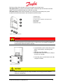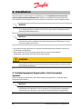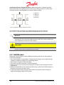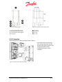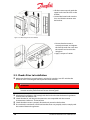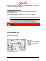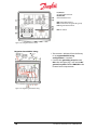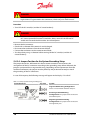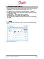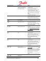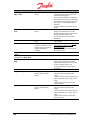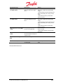
1
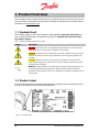
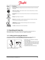
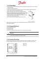
MAKING MODERN LIVING POSSIBLE DLX Installation Guide DLX 2.0 - DLX 2.9 - DLX 3.8 - DLX 4.6 SOLAR INVERTERS Danfoss can accept no responsibility for possible errors in catalogues, brochures and other printed material. Danfoss reserves the right to alter its products without notice. This also applies to products already on order provided that such alterations can be made without subsequent changes being necessary in specifications already agreed. All trademarks in this material are property of the respective companies. Danfoss and the Danfoss logotype are registered trademarks of Danfoss A/S. All rights reserved. Copyright ©: Danfoss, 2012 II Installation Guide DLX series L00410622-01 Contents 1. Product Overview ....................................................................................................... 4 1.1. Symbols Used ............................................................................................................................................ 4 1.2. Product Label ............................................................................................................................................. 4 2. Installation .................................................................................................................. 8 2.1 Safety Equipment Required for Grid Connected Systems .......................................................... 8 2.2. Mechanical Installation .......................................................................................................................... 9 2.3. Checks Prior to Installation ................................................................................................................. 12 2.4. Electrical Installation ............................................................................................................................. 13 2.5. Required Safety Equipment................................................................................................................ 23 2.6. Checks before Start Up ......................................................................................................................... 24 3. Start Up ...................................................................................................................... 25 3.1. Initial Start ................................................................................................................................................. 25 3.2. Self Test for Italy ...................................................................................................................................... 36 4. Connection between Inverter and PC ..................................................................... 38 4.1. Without a Network ................................................................................................................................. 38 5. Internal Web Server .................................................................................................. 39 6. Troubleshooting ....................................................................................................... 40 6.1. Check List by Failure .............................................................................................................................. 40 6.2. Table of Events ........................................................................................................................................ 40 7. Maintenance and Disposal....................................................................................... 44 7.1. Regular System Inspection ................................................................................................................. 44 8. Warranty .................................................................................................................... 45 8.1. Warranty Disclaimer .............................................................................................................................. 45 8.1.1. Damage .................................................................................................................................................. 45 8.2. End of Life Disposal ............................................................................................................................... 45 9. Technical Data........................................................................................................... 47 Installation Guide DLX seriesL00410622-01 III 1. Product Overview This Installation Guide contains all the necessary install information to connect and start up the DLX inverter. The inverter must be used in compliance with the DLX User Guide, which is to be found at www.Danfoss.com. 1.1. Symbols Used The warning symbols used in this Installation Guide highlight important information on how to avoid shock hazards to equipment and persons. Pay particular attention when the symbols appear! Table 1.1: Warning symbols appearing in this guide Symbol Description DANGER: Situations where an immediate hazard could cause serious injury or death to workers and/or the general public if not avoided. WARNING: Situations where a potentially hazardous condition exists that could result in the death or serious injury of workers and/or the general public if not avoided. CAUTION: Situations where a non-immediate or potential hazard presents a lesser threat of injury that could result in minor or moderate injuries to workers and/or the general public. NOTICE: Situations where a non-immediate or potential hazard presents a risk to damage of property and equipment. May be used to indicate important operational characteristics. There is no Safety Alert or attention symbol present in this situation. 1.2. Product Label The product label contains important identification parameters and characteristics for the inverter, and must be clearly visible after installation. Figure 1.2.1: Product Label 4 Installation Guide DLX series L00410622-01 Table 1.2: Symbols appearing on the product label Symbol Description Discharge time: High voltages may be present inside the inverter for 1 hour after switch OFF Refer to User Guide: Look for further details in the User Guide, which is available on the Danfoss website Hot Surface: The heat sink on the back of the inverter can reach temperatures up to 90 °C Danger: High voltages are present Disposal: Do not dispose in general waste! Collect the various parts separately and recycle them according to local regulations CE Marking: The product meets the EU safety, health and environmental protection requirements S – NO: Serial Number for inverter identification 1.3. Unpacking and Inspection After unpacking the inverter safely, check that all components are present and in an undamaged condition. If damaged, contact your supplier immediately! 1.3.1. Lifting and Carrying the Inverter Considering the inverter’s weight of 20-22 kg, (depending upon model), lifting and carrying the inverter must be correctly performed to prevent back injuries. • When lifting, bend the knees, and keep the back straight. • Lift carefully; hold the inverter close to the body and let the leg muscles do the work. • Turn the whole body as one unit to avoid twisting the lower back. • Carry the inverter close to the body. Figure 1.3.1: Correct lifting of the inverter Installation Guide DLX seriesL00410622-01 5 1.3.2. Unpacking • Place the box in position, with the top clearly visible and according to the arrow marking on the packaging. • Cut the seal, and open the box. • Take out the lock clip, the bag with accessories and the Installation Guide lying on the upper section of the foam packaging material. • Remove the upper part of the foam packaging material. • Both sides of the inverter case are narrowed in order to get a better grip on the device. Lift up the inverter carefully out of the box using the “handles” illustrated in Figure 1.3.2. • Remove the lower section of the foam packaging and take out the inverter mounting bracket. • Store all the original packaging for possible later reuse. Figure 1.3.2: “Handles” After unpacking the inverter safely, check that all components are present and in an undamaged condition. 1.3.3. Scope of Delivery • DLX single phase inverter • Mounting bracket • Installation Guide • Accessories: grounding strap, bracket screws, lock clip, extra type label NOTICE The mating parts of the connectors are not part of the standard scope of supply, and must be provided by the system installer. 1.3.4. Inverter Structure The housing of the DLX series inverter is designed for indoor and outdoor use (IP65), and provides a degree of protection from dirt, rain, sleet, snow, dust, water, and corrosion. H: 610 mm W: 353 mm D: 158 mm Figure 1.3.3: Mechanical dimensions 6 Installation Guide DLX series L00410622-01 The front surface of the inverter consists of an upper and a lower cover. The upper cover may only be removed by Danfoss authorized personnel. Removal of the upper cover by unauthorized persons voids the warranty! The lower cover protects the connection area, and may be removed by the system installer for electrical connection and maintenance of the inverter. 1. Upper cover 2. User Interface 3. Lower cover; customer connection area 4. AC output 5. DC input 6. Network input Figure 1.3.4: Inverter structure DANGER Always disconnect the PV array cables from the inverter after turning the AC and DC OFF, but before removing the covers, as the PV array can supply up to 600 VDC to the inverter when exposed to sunlight. • Loosen the four screws on the lower cover with a 4 mm hex key, according to the figure. • Take the cover off carefully. • Store the lower cover and screws safely to avoid loss or damage. • Fasten the screws on the lower cover with a torque of 1.0 Nm. Figure 1.3.5: Lower cover CAUTION Never remove the inverter lower cover in wet conditions! Removal of the inverter lower cover during rain or in damp conditions can damage sensitive internal electronic components. Installation Guide DLX seriesL00410622-01 7 2. Installation The DLX inverters contain no user-serviceable parts, and installation and maintenance must be performed by qualified persons, who have a qualified knowledge of the local and national electrical regulations and who follow the instructions in this Installation Guide. NOTICE The DLX series is a grid interactive (grid-tie) inverter and must be used exclusively for its designed purpose, which is to convert PV-generated DC electricity into AC electricity to feed into the grid. NOTICE The DLX series require minimum 7W PV power and a DC voltage above 230V for commissioning. An installation cannot be finished without 7W PV power. A small DC power supply can be used. • The inverter must be operated in its original and technically intact condition without any unauthorized modifications. • Always keep the values of operation within the limits given in the technical specifications, due to the risk of possible inverter damage. WARNING The safety precautions and instructions in this Installation Guide must be read thoroughly to be able to install and operate the inverter properly to prevent death, injury or material damage. 2.1 Safety Equipment Required for Grid Connected Systems Ensure compliance with the local and national electrical regulations to satisfy the safety equipment requirements. NOTICE The system installer is responsible for providing safety equipment that meets the requirements for both the DC and AC operations, and to protect the equipment and prevent personal injury, as per the local and national electrical regulations. 8 Installation Guide DLX series L00410622-01 2.1.1. Disconnection Devices Disconnection devices, switches or circuit breakers, enable a shut-off from the power source during operation. They protect the current-carrying conductors and other system components from power surges and system malfunctions, and help to shut down the inverter safely for maintenance and repairs. • Both AC circuit breaker(s) and DC switch(es) are recommended to facilitate maintenance work and repairs of the inverter. • The disconnect devices must conform to the local and national electrical regulations, and have an interrupt rating sufficient for the voltage and current available in the circuit. • Each disconnection device must be readily accessible and operable without exposing the operator to live parts. All devices must be permanently marked for their purpose. 2.1.2. Overcurrent Protection Devices Overcurrent protection devices, fuses or circuit breakers, prevent the circuit conductors from overheating as a result of overload, short circuit or ground fault. • An overcurrent protection device is required on every current carrying conductor. • If a fuse blows or a circuit breaker trips the cause should always be determined before replacing or resetting them. • It is recommended to install an RCD (Residual Current Device) of type A between the AC grid and the inverter, to be able to detect leakage current and interrupt fault paths. The needed detection range must comply with the relevant local and national electrical regulations! 2.2. Mechanical Installation The mounting surface and the mounting method must be suitable for the inverter’s weight, dimensions and possible housing temperature. This is crucial to maintaining the efficiency of the inverter! WARNING Correct installation prevents the inverter from falling from the wall! The mounting surface must be suitable for the weight 20-22 kg and temperature (90 °C) of the inverter. CAUTION Protect the inverter from flammable and explosive environments, as the inverter heat sink can reach temperatures up to 90 °C during long-periods of high performance. • The inverter is suitable for outdoor operation, but should be sheltered from direct sunlight, snow, rain, dust and sand. • Location should be in proximity to the PV arrays to minimize DC losses. Installation Guide DLX seriesL00410622-01 9 Avoid enclosed areas with poor air flow! Sufficient ventilation is needed to prevent temperature build up inside the inverter and hence possible power losses. Observe the minimum distances specified below to maintain optimal cooling: 1. 400 mm 2. 300 mm 3. 150 mm 4. 150 mm Figure 2.2.1: Minimum distances for optimum cooling For optimal operating conditions, the ambient temperature must be between -25° C & +65° C, and non-condensing relative humidity between 4 % and 99 %. NOTICE Direct sunlight may cause yield losses, as direct sunlight causes increased internal temperatures that can lead to reduced power output. Also, direct sunlight may cause degradation of the LCD screen quality. CAUTION Ensure a location where people cannot accidentally come in contact with the rear inverter surface, due to temperatures up to 90°C. 2.2.1. Wall Bracket Depending on the mounting surface, different mounting methods may be required to secure the wall bracket. • The system installer is responsible for selecting the correct type and number of fixings suitable to support the weight on the mounting surface. • The bracket is designed to withstand 80 kg • The inverter must be mounted in a vertical orientation. • Keep the lower cover closed when mounting the inverter to avoid damage to internal components. • Mark the bracket holes on the mounting surface using a spirit level and the bracket as a template to ensure the inverter is level. • Fasten the bracket to the mounting surface with the required number of fixings to support the hanging weight of the inverter. 10 Installation Guide DLX series L00410622-01 Figure 2.2.2: Inverter bracket Figure 2.2.3: Distances between fixing screws 1. Carrier slots for the inverter 2. Steering slots for the inverter 3. Carrier slots for the Stringbox 4. Fixing clip D1. 232.5 mm D2. 232.5 mm D3. 75 mm D4. 75 mm 2.2.2. Inverter Attach the inverter to the mounting bracket as follows: • Locate the hooks for the carrier slots on the upper back and the hooks for the steering slots on the lower back of the inverter. • Use the locating pins on the Stringbox. Figure 2.2.4: Hooks on the back of the inverter Installation Guide DLX seriesL00410622-01 11 • Lift the inverter up and guide the upper hooks into the slots on the bracket. • Control the lower hooks into the slots and slide the inverter onto the bracket. Figure 2.2.5: Mounting Inverter onto bracket • Ensure that the inverter is correctly mounted, and tighten the lock clip with one screw into the inverter and one into the Stringbox. • Apply a torque of 1.0 Nm 2.3. Checks Prior to Installation Make sure that the AC circuit breaker(s) and the DC switch(es) are OFF and that the terminals are in a discharged state to prevent shock hazards. DANGER Contact with energized ports may cause lethal injuries! All installation of the inverter must be performed with circuits de-energized! All electrical installations shall comply with the local and national electrical regulations in force at the installation site. Check that the PV and the grid characteristics are compatible with the inverter characteristics. Refer to 9. Technical Data Check that the inverter is properly fastened and secured to the bracket. Ensure that the conductors and circuit breakers/fuses are properly sized to comply with the national electrical regulations. 12 Installation Guide DLX series L00410622-01 Ensure that the conductors are listed for PV applications and the site environment, and that they have the correct color coding. 2.4. Electrical Installation Contact the local utility company for interconnection agreements and power approval before connecting to the grid. Correct electrical connection is critical for achieving a safe, long-term and reliable operation of the entire PV system. NOTICE Only persons who are qualified to install high voltage electrical equipment and are familiar with the electrical regulations applicable to the installation site may install the inverter. This is to ensure a safe connection and avoid electrocution! DANGER Never work with live wires! All work on the inverter must be performed with disconnected terminals, as contact with live wires may cause serious injury or death! 2.4.1. Connection Area The DC connections are achieved by the use of a Stringbox with DC switch and three sets of DC connectors. The connection of the AC and the network cables are with screw terminals and a RJ45 connector. 1. CAN bus terminal 2. RS-485 terminal 3 Ethernet port 4. Internal DC terminal blocks, +POS and -NEG 5. Internal DC ground receptacle, GND/PE 6. Stringbox equipped with DC switch 7. Internal AC terminal block Figure 2.4.1: Stringbox with DC switch Installation Guide DLX seriesL00410622-01 13 2.4.2. Grounding Appropriate grounding of the entire PV system limits voltage surges, gives a common reference point for the conductive parts and facilitates the operation of the overcurrent devices. NOTICE • Grounding must be carried out by qualified persons only and comply with local and national electrical regulations. • Follow the safety instructions and specifications from the different PV module manufacturers regarding grounding requirements. • The PV strings may be ungrounded, or grounded through either the negative or the positive string conductors. • The grounded DC conductors are connected to ground via the grounding strap. • The grounded conductors must be sized according to the local and national electrical regulations, and only carry current when electrical malfunctions occur. • All metal parts of the DLX inverters are electrically bonded to ground through the terminal labeled GND in the AC terminal block. CAUTION If the positive or negative PV conductors are grounded, then the grounding strap must be connected to the DC ground terminal and the system must NOT be grounded at any other point, as voltage potentials can appear and possibly damage electrical components. A minimum cross section area of 6.0 mm² / 10 AWG is required for the ground wire connection. 2.4.3. DC Connections (PV) The DC connections include wiring from the PV modules, through the combiner box, to the inverter. DANGER Always disconnect the PV array before starting the connection on the DC side! Charged DC terminals pose a risk of serious injury or death as the PV array can supply up to 600 VDC to the inverter when exposed to sunlight. WARNING Never remove cables during operation! The inverter is charged with high voltages, and removal of cables during operation may cause arcing 14 Installation Guide DLX series L00410622-01 NOTICE Maximum Voltage: The open circuit voltage, VOC, must never exceed 600 VDC under any conditions. The voltage generated by PV modules is inversely proportional to the temperature; at lower temperatures the PV voltage increases from the nameplate rating and at higher temperatures the PV voltage decreases from the nameplate rating. NOTICE Ensure the DC switch in the Stringbox is in the OFF position, when removing the lower cover to access the connection terminals. 0 = OFF I = ON Figure 2.4.4: DC switch 2.4.3.1. Stringbox with DC switch The Stringbox is equipped with DC switch and plug-in connectors. P1, P2, P3: Positive connectors N1, N2, N3: Negative connectors Figure 2.4.5: Optional DC connectors and DC switch Installation Guide DLX seriesL00410622-01 15 P1, P2, P3: Ungrounded terminals N1, N2, N3: Grounded terminals N4: Grounded terminal N5: Terminal for the grounding strap P4: Ungrounded terminal DS: DC Switch Figure 2.4.6: Stringbox with DC switch Negative Grounded PV String • The inverter is delivered from the factory in an ungrounded PV string configuration as standard. • Connect the grounding strap between N5 in the Stringbox (fig. 2.4.6) and the DC ground receptacle labelled GND/PE in the inverter lower compartment. Figure 2.4.7: Negative grounded PV string 16 Installation Guide DLX series L00410622-01 Positive Grounded PV String • Connect the positive connectors (+) to the terminals labelled 2.Grounded and the negative connectors (-) to the terminals labelled 1.Ungrounded. • Switch the conductors connected to N4 and P4 (fig. 2.4.6). • Connect the grounding strap between N5 in the Stringbox (fig. 2.4.6) and the DC ground receptacle labelled GND/PE in the inverter lower compartment. Figure 2.4.8: Positive grounded PV string 2.4.3.2. Connection Procedures • The DC conductors connecting the PV array to the inverter must each have a minimum rating of 600VDC at all given operating temperatures. • The DC conductor cables must be sized for correct temperature rating and sunlight resistance. Use copper wire with a cross-section area of between 6 mm2 to16 mm2 / 10 AWG to 6 AWG and temperature rating 90° C for all connections. Ensure compliance with the relevant national electrical regulations! • Conductor insulation rating must be higher where the backs of the modules cannot receive cooling or where the ambient temperature exceeds 40° C. Note the relevant national electrical regulations! String Connectors • The corresponding mating connectors must be provided by the system installer. • Follow the guidelines from the connector manufacturer when choosing cable sizes and assembling them in the connectors. • Plug in the connectors and hand-tighten them to the corresponding connector on the inverter. • Check if the contacts are firmly tightened by pulling them gently. • Only valid for France: Removal of the connectors requires a special tool. Note the relevant national electrical regulations! 2.4.3.3. Reversed DC Connection If the positive and negative conductors are connected to the wrong terminals, the inverter will not start up. The inverter is not damaged due to internal reverse blocking diodes, but high currents are generated in the conductors. Installation Guide DLX seriesL00410622-01 17 DANGER Be aware of high currents! If the DC terminals are mixed up during connection, high currents are generated in the conductors, which can pose shock hazards. Procedure • Turn OFF the DC switch(es) and the AC circuit breaker(s). DANGER The PV conductors are still charged after the DC switch in the Stringbox is turned OFF, due to power fed from the PV modules. Always turn OFF the remote DC switch and wait until the PV modules do not feed power. • Remove the PV connectors. • Check with a voltmeter if the terminals are discharged. • Disconnect the conductors from the terminal block. • Connect the conductors to the correct terminal block. • Test the polarity using a voltmeter before turning ON the DC switch(es) and the AC circuit breaker(s). 2.4.3.4. Jumper Position for the System Grounding Setup The jumper above the - NEG terminal in the customer connection area monitors the arrangement of the DC connection according to the grounding setup. When delivered, the jumper is positioned for an ungrounded string. Depending on the requirements from the module manufacturer, the jumper must be pulled up and positioned correctly to match the grounding of the DC conductors. In case of discrepancy the following message will appear in the display: “Fuse fault.” Table 2.4.1: Jumper position for the grounding setup Connection Area Top view System Ungrounded PV String Configuration: There is no connection between the pins. Positive grounded PV String Configuration: The jumper short-circuits the two leftmost pins. Negative grounded PV String Configuration: The jumper short-circuits the two rightmost pins. 18 Installation Guide DLX series L00410622-01 2.4.4. AC Connections (Grid) The AC connection includes wiring from the AC distribution panel through one or more circuit breakers to the AC terminal block of the inverter. Verify that the AC grid specifications are compatible with the inverter characteristics before connecting the inverter to the grid: • Single phase / Split phase • Voltage range (184 – 276 VAC) • Frequency range (50 Hz ±5 Hz) DANGER Turn OFF the AC circuit breaker before connecting the inverter to the AC grid to prevent electrocution. The DLX series are single phase output inverters, which are designed so that they can be connected to a three-phase system. When several inverters are connected together, they must be distributed evenly between the grid phases. Single Phase Three Phase Figure 2.4.9: Example inverter AC connections Table 2.4.2: The different AC conductors Term (Abbr.) Description Phase conductor (L1/L2/L3) Neutral conductor (N) The ungrounded live conductors, which carry current to the load. In a single phase system the neutral conductor is a circuit conductor carrying the same amount of current as the ungrounded phase conductors. An electrical path to ground, designed to carry fault currents. PE (Protective Earth / Ground) conductor Installation Guide DLX seriesL00410622-01 19 2.4.4.1. Connection Procedures Figure 2.4.10: Connection area with AC terminals 1. AC terminal block: • GND: Ground terminal • N: Neutral terminal (TN/TT) or Phase terminal (IT) • L: Phase terminal 2. Cable gland • Use copper wire with a maximum cross-section area of 16 mm2 / 6 AWG. Ensure compliance with the relevant national electrical regulations! • The AC conductor resistance should be minimized. • Unscrew the cable gland locknut. • Guide the AC cable through the opening, and connect the conductors to the corresponding terminals in the connection area: • Phase conductor (L1 or L2 or L3) to L • Neutral conductor (TN/TT) or Phase conductor (IT) to N • Grounded conductor to GND • Tightening torque of the terminal screws is 1.5 Nm • Double check if the connection is correctly carried out. • Hand-tighten the gland locknuts to seal the cable gland. 20 Installation Guide DLX series L00410622-01 2.4.5. Network Connections The inverter is equipped with three communication interfaces: Ethernet, CAN, and RS-485. Ethernet provides communication between the integrated web server and a computer, either directly or via a router/switch. CAN allows communication between several DLX inverters. RS-485 allows communication with Danfoss compatible third party products or to Danfoss CLX products. 1. Follower inverter 2. Master inverter 3. CAN bus cable 4. Ethernet cable 5. RS-485 cable 6. Computer 7. Data logger Figure 2.4.11:Connection without network 2.4.5.1. Connection Procedures Figure 2.4.12: Connection area with network terminals 1. CAN bus terminal 2. RS-485 terminal 3. Ethernet connector 4. Network cable gland NOTICE If multiple inverters are connected together, all inverters must be connected to the CAN bus before Start Up to benefit from single installation setup. Installation Guide DLX seriesL00410622-01 21 • Ethernet: Use CAT5e or better, with size 0.21 mm2 /24 AWG, with a maximum total length of 100 m. • CAN: Use CAT5e or better, with size 0.21 mm2 /24 AWG, with a maximum total length of 500 m. • RS-485: Use CAT5e or better, with size 0.21 mm2 /24 AWG, with a maximum total length of 1200 m • Unscrew the network cable gland, and take out the grommet. • Three-way cable gland insert: Figure 2.4.13: Insertion of the network cables in the cable gland 1. Conductors with connector: cut through the grommet with a width of about 1mm. With no connector: no cutting is necessary 2. Remove the plug from inside the grommet. 3. Assemble the cable in the gap. Repeat step 1 – 3 if more cables. 4. Guide the assembly into the cable gland. 5. Connect the cables to the terminals in the connection area as follows: - Ethernet: - CAN: - RS-485: Plug the Ethernet cable directly into the RJ45 socket. The conductors must be connected to the same labeled terminals at both ends, i.e. H connected to H, L to L etc. Recommended tightening torque is 0.2 Nm / 0.15ft-lbf. The conductors must be connected to the same labeled terminals at both ends, i.e. A connected to A, B to B etc. Recommended tightening torque is 0.2 Nm / 0.15ft-lbf. 6. Tighten the cable gland firmly. NOTICE Cable shielding: It is recommended to mount the cable shielding for both the CAN and RS-485 with the GND at the receivers end. If any kind of datalogger is connected to an inverter, then only mount the shield at the datalogger. If the system consists of two or more inverters, then only mount the shield at the “Master” 22 Installation Guide DLX series L00410622-01 CAN and RS-485 connection pinout CAN B(+) A(-) GND B(+) A(-) GND H L COMGND H L COMGND RS-485 2.4.5.2. Jumper Position for Termination Resistance With multiple inverters connected the jumper located behind the CAN / RS-485 terminal activates the termination resistance when the pins are terminated (short-circuited). This minimizes signal reflections in the cables and helps to avoids interference. • Single inverter: The two pins must be terminated (Default). • Several inverters connected: The master-follower configuration requires terminated pins on the first inverter and on the last inverter in the linked series. The pins must be disconnected on the inverters between the first and last inverters in the linked series. • To disconnect the pins, the jumper must be pulled up and placed only on one of the pins. • Be careful not to bend the pins when removing or installing the jumper! Table 2.4.3: Jumper for multiple inverters in linked series Network connection Jumper Position Pins The pins are terminated. The pins are disconnected. 1. CAN termination resistance 2. RS-485 termination resistance 2.5. Required Safety Equipment Safety equipment includes switches or circuit breakers to disconnect power sources, fuses or circuit breakers to protect conductors from overheating and surge protection to protect the equipment from voltage bursts and surges. Installation Guide DLX seriesL00410622-01 23 NOTICE Safety Equipment: The system installer is responsible for providing safety equipment that meets the requirements for both the DC and AC operations to protect the equipment and prevent personal injury. 2.6. Checks before Start Up Mounting: - Check that the bracket and the inverter are correctly mounted and secured. PV wiring: - Check that the PV cables are rated for the PV current and for the present environmental conditions. - Check that the wiring is performed according to local and national electrical regulations. Connection: - Check that the PV conductors are correctly torqued to the DC terminals. - Check that all connectors and cable glands are correctly tightened and sealed. DC side: - Verify that the PV open-circuit voltage (VOC) does not exceed 600 VDC - Check that the DC polarity is correct. AC side: - Verify that the AC conductors are correctly connected to the AC terminals. Grounded conductors: - Check that the grounded conductors are properly sized, and not fused or switched. Jumpers: - Check that the jumpers for the grounding setup and for the termination resistance are correctly positioned according to the grounding setup. Disconnects: - Ensure that all current-carrying conductors on both the DC and AC sides have a switch, and that the switch is located correctly and is readily accessible. Overcurrent protection: - Ensure that the overcurrent protection on both the DC and the AC sides are rated correctly, and capable of being changed without touching live contacts. Inverter cover: - Ensure that no cables interfere with the sealing of the inverter lower cover, and fasten the cover firmly to the housing. Recommended tightening torque is 1.0 Nm CAUTION Verify that the lower cover is correctly tightened, so that no moisture enters the housing and damages the electronic components. 24 Installation Guide DLX series L00410622-01 3. Start Up A minimum available voltage of 184 VAC, 230 VDC and a power greater than 7 WDC is required before the inverter starts feeding power to the grid. AC side • Turn ON the AC circuit breaker(s). DC side • Turn ON the DC switch(es). 3.1. Initial Start When the inverter is started for the first time, an installation menu is automatically displayed to enable the configuration of certain critical values and operational settings. 3.1.1. Customizing the Inverter Settings Single Inverter • When both the DC and the AC switches are turned ON and the inverter is supplied with enough power, an installation menu is displayed in the LCD screen. Multiple Connected Inverters 1. CAN • Connecting all inverters via the CAN bus enables the configuration of all inverters in a plant via one inverter. The Start Up can then be carried out on any inverter, and if configured as the master inverter the configuration settings of time, date, language and grid settings will be transferred to all the other follower inverters on the network. • Each follower inverter is automatically assigned an ID number from the master during Start Up. 2. RS-485 • Connecting the inverters via the RS-485 bus enables communication with third party equipment. • Each inverter must manually be assigned an ID, a bit rate number and a parity number: - The ID number must be between 1 and 247. - Both the master inverter and the follower inverters need a bitrate number and a parity number. Compare with the setup in the third party equipment (eg. an external data logger) and write this number in the inverter’s network menu. Refer to section 6.2.4.2 Network Setup of the User Guide for more details. Defaults are: bitrate – 19200 and parity – none. Installation Guide DLX seriesL00410622-01 25 3.1.2. User Interface The User Interface on the front of the inverter contains a LCD screen, three LEDs and six function keys. Figure 3.1.1: Inverter user interface • To activate the display when the screen saver is active (blank), press any key. • With sufficient AC power the display shows the Start Up screen. 3.1.2.1. Function keys The function keys have the following uses: Table 3.1: Function keys Symbol Function Symbol Function Up: Scroll up / increase value Right: Navigate one page or value right Down: Scroll down / decrease value Enter: Select option / go to next level Left: Navigate one page or value left Cancel: Stop operation / back to previous menu item • The selected item is always highlighted in yellow. • A registered touch of a button causes a “click” sound to be heard. 26 Installation Guide DLX series L00410622-01 3.1.2.2. LED There are three LEDs next to the display screen. The upper one is red, the middle is yellow and the lower one is green. Table 3.2: LEDs. Symbol NONE LED Function Action Red Malfunction! Inverter in shutdown mode Look for alarms in Active Alarms Green & Yellow Caution! Inverter still operates, but at a limited level Look for warnings in Active Alarms Green Operates; inverter feeds power to the grid No action Yellow Inverter is OFF (Power < 7WDC) No action 3.1.2.3. LCD Screen To navigate in the LCD screen the six function keys must be used. By selecting one of the seven items in the Main Menu, a further navigation through different submenus is possible. There are four different menu levels. Home, Status, Event Log, Statistics: The information and values are read-only. Setup, Commands, Alarm Setup: The information and values can be modified. Figure 6.2.1: Main Menu Padlock: Opens up when correct password is entered. Lines: Number of highlighted lines indicates the current menu/submenu level, with the top line being the first level (Main Menu). Installation Guide DLX seriesL00410622-01 27 3.1.3. Start Installation configuration 1. Start Left – Cancel Right – OK Enter – Confirm 2. Language Selection Default – English Enter – Call up the list of languages Up or Down – Navigate through the list to find the preferred language; English, German, French, Spanish, Italian, etc.. Enter – Confirm Right – Next Enter – Confirm 3. Date DD.MM.YYYY Enter – Call up the date Up – Increase present digit Down – Decrease present digit Right – Select next digit Left – Select previous digit Enter – Confirm Left – Back Right – Next Enter – Confirm 28 Installation Guide DLX series L00410622-01 4. Time HH.MM (24 H) Enter – Call up the time Up – Increase present digit Down – Decrease present digit Right – Select next digit Left – Select previous digit Enter – Confirm Left – Back Right – Next Enter – Confirm NOTICE The time setting must match the time on the actual installation site, otherwise data may be overwritten! 5. Set Bus ID Enter – Call up the digits Up – Increase present digit Down – Decrease present digit Enter – Confirm Left – Back Right – Next Enter – Confirm If RS485 communication is used, set a unique bus ID for the inverter. For any follower inverters, this will be required to be set manually under Setup > Network Setup > Bus ID (RS485). If RS485 communication is not used, this step can be missed. 6. Set as Master Unit Default – No Enter – Call up the options: Yes or No Up – Yes Down – No Enter – Confirm Left – Back Right – Next Enter – Confirm Installation Guide DLX seriesL00410622-01 29 If the inverter is set to master, data must be collected from the follower inverters. The following screen is displayed: 7. Grid Configuration Enter – Call up the list of grid configurations Up or Down – Select the grid configuration of the actual installation site: TN/TT, IT, Undefined Enter – Confirm Left – Back Right – Next Enter – Confirm 8. Feeding Phase Enter – Call up the list of phases Up or Down – Select the preferred phase: - TN/TT: Not set, L1, L2, L3 - IT: Not set, L1-L2, L1-L3, L2-L3 Enter – Confirm Left – Back Right – Next Enter – Confirm If the inverter is set to master, and there is more than one inverter in the plant, the following screen is displayed: 30 Installation Guide DLX series L00410622-01 If the inverter is configured as master: step through and set phase values (L1, L2, L3, L1-L2, L1-L3, L2-L3) for all follower inverters. 9. Plant Apparent Power Plant apparent power is used to determining some VDE 4105 default settings. The value shown in the installation menu is a suggestion and must be confirmed. Please call up the digits and change value if required before pressing Enter. Enter – Call up the digits Up – Increase present digit Down – Decrease present digit Enter – Confirm Left – Back Right – Next Enter – Confirm 10. Grid Code Enter – Call up the list of grid codes Up or Down – Scroll through the list to select the required grid code for the actual installation site: Enter – Confirm Left – Back Right – Next Enter – Confirm Installation Guide DLX seriesL00410622-01 31 CAUTION The selected grid code must match the actual installation site; otherwise the inverter may not operate or be compliant to relevant local and national regulations due to incorrect limit values. NOTICE • UK: Follow the local electrical regulations when selecting the grid code; either normal grid code setting or UK 16A Limit restricted grid code setting with a 16A limitation for G83 compliance. • Germany: Follow the local electrical regulations when selecting the grid code setting; either Germany 126 (VDE 0126-1-1) or Germany 4105 (VDE-AR-N 4105). The following screen is displayed while the settings are updated: Grid Code Selection NOTICE An installation timer ensures that the grid settings can be changed (using the Owner password) within 5 hours of feeding power to the grid. Thereafter it is only accessible using the Installer password, which may only be obtained for installers and grid operators by contacting Danfoss. 11. Reactive Power Setting Enter – Call up the options Select the actual reactive power setting: 1. For installations <= 13.8 kVA: VDE 4105 0 – 13.8 2. For installations > 13.8 kVA: VDE 4105 13.8 – Enter – Confirm Left – Back Right – Next Enter – Confirm 32 Installation Guide DLX series L00410622-01 12. Screen Timeout Enter – Call up the digits Default – Screen backlight OFF after 60 sec Left – Back Right – Next Enter – Confirm NOTICE The smallest value to be set is 30 sec, and the highest is 99 sec. Setting the value to 0 disables the screen timeout and leaves the screen backlight ON at all times. 13. Customer Name Enter – Call up the keyboard The keyboard enables the typing of a customer name. Left – Back Right – Next Enter – Confirm In some of the submenus the settings must be typed by using the function keys: Letter keyboard Installation Guide DLX seriesL00410622-01 Number keyboard 33 Table 5.2: Symbols appearing in the type screens Symbol Description Symbol Description Upper- or lower-case letter Confirm changes and exit the menu Point Clear the typing field Space Go back without saving changes Cancel last letter Go to the Letter keyboard Go to the Number keyboard • Enter must be pressed until the wanted letter/number/symbol is shown. • It is possible to navigate between the characters by using the Up arrow to set the marker into the text window, then using Left and Right to navigate between the characters. • There is space for a maximum of 19 characters in the text window. 14. Site Enter – Call up the keyboard The keyboard enables the typing of a site name. Left – Back Right – Next Enter – Confirm 15. Unit Name Enter – Call up the keyboard The unit name helps to distinguish and identify specific inverters in a large PV plant. Left – Back Right – Next Enter – Confirm 34 Installation Guide DLX series L00410622-01 16. Message Enter – Call up the keyboard This message field is to help distinguish and identify specific inverters in a larger PV plant, or for any other information. Left – Back Right – Next Enter – Confirm 17. Owner Password Enter – Call up the digits Default: 0003. Change the password to 4 optional digits Left – Back Right – Finish Enter – Confirm NOTICE With several inverters connected it must be checked that the installation is carried out on all the follower inverters. • Look at the displayed menu and the LEDs: It is not carried out correctly if the installation menu is still displayed and/or the green LED is not lit and the yellow and red LEDs are lit. • Check that the connection of the CAN cables are correct, that the AC and DC switches are ON and that the voltage are >184 VAC, and >230 VDC and there is greater than 7 WDC of power • If the Start Up phase is correctly carried out the inverters are ready to use. They are fully automatic during normal operation, and no manual control is necessary for feeding power into the grid. A warning box is displayed if an error occurred during installation: Installation Guide DLX seriesL00410622-01 35 Warning Box Errors: 1. No communication 2. Wrong grid settings • Check the LEDs on the inverters. If the yellow and red are lit check that the installation is correct performed and that the grid settings are correctly set. • If the ‘Start Installation’ screen is still shown, run through the installation process on the inverter. 3.2. Self Test for Italy The Self Test function is only valid for installation in Italy. It tests the inverters’ grid monitoring function of voltage and frequency, and takes approximately 2 minutes. NOTICE The Self-Test can only be activated when: • The installation procedure is executed. • The country setting is set to Italy. • The inverter is in Running/Derating Mode. Select: Commands>Inverter Commands>Self Test 36 Installation Guide DLX series L00410622-01 • • • • The inverter carries out four test sequences, all of which are displayed on the screen. After the test is finalized, each test result must be confirmed by entering Next. After entering Finish on the last result, the screen displays the Inverter Commands menu. The test results can be found in Commands>Inverter Commands>Results Self Test. Refer to User Guide for more detailed information about the Italian Self Test Installation Guide DLX seriesL00410622-01 37 4. Connection between Inverter and PC The site performance can be checked remotely by using a computer. The connection can be achieved between the inverter and the computer either directly or via a network. 4.1. Without a Network To connect the inverter and the computer directly a regular Ethernet cable is needed. If the network card in the computer does not support Autosense, a crossover cable is needed to create a connection to the inverter. 1. Follower inverter 2. Master inverter 3. CAN bus cable 4. Ethernet cable 5. RS-485 cable 6. Computer 7. Data logger Figure 4.1.1:Connection without network NOTICE With several inverters connected together via CAN bus the Ethernet cable must be attached to the master inverter only. 4.1.1. IP Address The computer’s and the inverter’s IP address must be in the same range. If the inverter’s IP address is 192.168.10.X, the computer’s IP address must be 192.168.10.Y, where X and Y are different numbers between 1 and 254. Inverter The inverter’s default IP address is 192.168.10.20. To change the IP address, go to Setup>Network Setup and set the inverter’s IP address as required. To connect the PC and the inverter, the inverter’s IP address must be entered into the PC web browser address line. Refer to User Guide for more detailed information about Network setup 38 Installation Guide DLX series L00410622-01 5. Internal Web Server The inverter has an internal, onboard web Server providing detailed information about the operation, warning/alarms and energy production from the inverter/plant. • The web page is best viewed in Firefox 6.0 and Internet Explorer 8.0 or later versions. • From the web page certain inverter settings can be changed after applying the correct user name and password. • Type the inverter’s IP address in the computer’s web browser. • Default administrator account is: User: admin, Password: admin. This can be changed by user, and should be changed if the web server is connected to the internet. 5.1. Home The Home screen is the standard display, which is always shown when opening the web server. Figure5.1: Web Server Home screen Installation Guide DLX seriesL00410622-01 39 6. Troubleshooting This chapter contains useful information if the inverter malfunctions during start-up or operation. Start by checking that the installation is carried out correctly, and then check the information in section 4.2 for possible solutions. If this does not help solve the problem, please contact the system installer. 6.1. Check List by Failure If the inverter does not feed power to the grid, try to solve the problem by checking: That the irradiation is sufficient to generate power (>7 W). That both the AC circuit breaker(s) and DC switch(es) are ON. That the operation mode of the LEDs is normal. Refer to 3.1.2.2. LED. That there are no warnings or alarms in the display. That all connection points in the system are properly tightened. That the values of the PV voltage, current and power match those in the display. If all these items are OK, and there is still no power fed to the grid, please contact the system installer. 6.2. Table of Events The inverter automatically identifies operational issues and displays the messages on the screen. Detailed information about warnings and alarms can be found in the Event Log menu. Messages that can appear in the display: W = Warning: inverter continues to operate at highest possible capacity (Yellow LED A = Alarm (Red LED) The Display Message code number (E01, E02, etc..) is the code shown in the event description as displayed in the Event Log of the webserver view: Table 7.1: Description of messages appearing in the display during inverter failure Display Message Panel fault (W/A – E01) Input circuit breaker open (A – E02) Description PV module failure DC switch(es) is open Inverter failure (W/A – E03) Output circuit breaker open (A – E04) Inverter failure AC circuit breaker(s) is open 40 Action - Contact the module supplier* - Turn ON the DC switch(es)* - If already ON, contact the system installer * - Turn ON the AC circuit breaker(s)* - If already ON, contact the system installer Installation Guide DLX series L00410622-01 Display Message Grid fault (W/A – E05) Description No detection of the grid, not able to synchronize with the grid or fault within the country-settings GUI fault (W/A – E06) Display is not responding High voltage on input side (A – E07) Low voltage on input side (A – E08) DC voltage threshold of 600 VDC is exceeded DC voltage is too low to operate the inverter Low PV isolation resistance (W – E09) PV isolation resistance is below permitted level Failure on DC side (W/A – E10) Inverter failure on the DC side Failure on AC side (W/A – E11) Inverter failure on the AC side High inverter temperature (W/A – E12) Maximum permissible internal inverter temperature is exceeded Low inverter temperature (W/A – E13) Low internal inverter temperature Installation Guide DLX seriesL00410622-01 Action - Verify if the AC circuit breaker is ON and operational - Measure that the grid voltage is present at the AC terminals - Check that the DC switch(es) is ON and that the DC power is > 7W - Check that the country settings have been successfully set in Setup>Grid Setup - If country is set to Italy, has the SelfTest failed. Run test again - Turn off the AC side. Wait for 3 seconds and then turn on again. Wait 30 seconds for the GUI to turn on - If still fault, contact your distributor - Contact system installer - Fault is cleared automatically when PV voltage exceeds 230 V - If the inverter remains in this fault during daylight, and the VDC is >230V, contact your distributor - The grounding setup is configured incorrect - Check the jumper for the grounding setup (Jumper Position for the System Grounding Setup ) - If the jumper is correct positioned, contact the supplier - Failure on the DC side. Other W/A will be displayed - If the inverter is in Shutdown, turn off the AC side and then the DC side. Wait for 30 seconds, then turn on the AC side and then the DC side - If the fault persists, contact your distributor - Failure on the AC side. Other W/A will be displayed - If the inverter is in Shutdown, turn off the AC side and then the DC side. Wait for 30 seconds, then turn on the AC side and then the DC side - If the fault persists, contact your distributor - Check that the ambient temperature is within the specification. Refer to 9. Technical Data - Check if the ventilation is sufficient, the minimum distances are compliant with those stated in this User Manual and the inverter is shielded from direct sunshine - Clean ventilation area. Refer to User Guide. - Contact your distributor 41 Display Message Current / power limitation (W/A – E14) Description PV power exceeds inverter rating Communication failure (A – E15) Internal communication failure Fan failure (W/A – E16) Internal air circulation has failed One or more fuses or circuit breakers are blown, or the jumper for the grounding setup is positioned incorrect Fuse fault (A – E17) Active power limitation (W/A – E18) Reactive power compensation (W/A – E19) Microprocessor fault (W/A – E20) Ground current trip (A – E21) High AC voltage (A – E22) Low AC voltage (A – E23) 42 Action - The inverter will try to start up again when the temperature is within the permissible range again - Check if the ventilation is sufficient, the minimum distances are compliant with those stated in this manual and the inverter is shielded from direct sunshine - Clean ventilation area. Refer to User Guide. - If the inverter is in Shutdown, turn off the AC side and then the DC side. Wait for 30 seconds, then turn on the AC side and then the DC side - If the fault persists, contact your distributor - Contact your distributor for replacement - Check the jumper position (2.4.3.4. Jumper Position for the System Grounding Setup) - Contact the system installer for DC fuse replacement * * Too high AC voltage, the inverter stops feeding power Too low AC voltage, the inverter stops feeding power - If the inverter is in Shutdown, turn off the AC side and then the DC side. Wait for 30 seconds, then turn on the AC side and then the DC side - If the fault persists, contact your distributor * - The inverter will restart when the voltage is within the permissible range - Check that the country settings have been successfully set in Setup > Grid Setup - If the failure persists, contact the system installer - The inverter will restart when the voltage is within the permissible range - Check that the country settings have been successfully set in Setup > Grid Setup - If the failure persists, contact the system installer Installation Guide DLX series L00410622-01 Display Message High frequency on output side (W/A – E24) Description The frequency of the utility voltage is above the upper limit Low frequency on output side (W/A – E25) The frequency of the utility voltage is below the lower limit High output DC current (W/A – E26) Too high proportion of DC current in the grid feed Output current imbalance (W – E27) Imbalance in the output current between the phases (3 phase only) Fault ride-through Grid fault, still running (W – E28) VDR fault DC side (W – E29) The varistors on the DC side are damaged. Action - The inverter tries to restart when the frequency is within the permissible range - Check that the country settings have been successfully set in Setup > Grid Setup - If the failure persists, contact the system installer - The inverter tries to restart when the frequency is within the permissible range - Check that the country settings have been successfully set in Setup > Grid Setup - If the failure persists, contact the system installer - The inverter tries to restart when the fault is cleared - If the fault still occurs, contact your distributor * * - Contact your distributor for new parts * Reserved for future use Installation Guide DLX seriesL00410622-01 43 7. Maintenance and Disposal Regular inspection of the PV system is an important safety precaution to ensure troublefree operation of the entire PV plant and the DLX inverter. Danfoss is committed to its policy of environmental responsibility, and therefore appeals to end users who are disposing of inverters to follow local environmental legislation and to seek safe and responsible means of disposal. 7.1. Regular System Inspection The DLX inverters are designed and manufactured to operate trouble-free for many years. Performing regularly maintenance will ensure high efficiency and a longer service life for the inverters. NOTICE • Prior to service and maintenance work the inverter should always be disconnected on both the AC and the DC sides and discharged to avoid shock hazards. • For service or maintenance the inverter must be de-energized for 1 hour to discharge the capacitor bank. • The inverter upper cover is to be opened only by Danfoss service persons or service partners authorized by Danfoss due to danger of damage to internal components and invalidated warranty. Refer to User Guide for more detailed information about the discharge procedure of the capacitor bank and about regularly maintenance of the inverter. 44 Installation Guide DLX series L00410622-01 8. Warranty The inverters are compatible with all relevant standards and are guaranteed to be free of defects from the date of purchase. 8.1. Warranty Disclaimer The warranty is void through misuse or when unauthorized repairs are performed on the inverter. The warranty does not cover normal wear and tear of the inverters or costs related to installation and troubleshooting of the electrical system. The warranty is only valid with an identifiable and accepted serial number. 8.1.1. Damage Danfoss takes no responsibility for damages to the inverter due to: • Unauthorized persons removing the inverter upper cover. • Unauthorized modifications made to the inverter. • Inverter is installed, commissioned, operated or maintained incorrectly. • Relevant safety regulations and instructions in this User Guide being ignored. • Inverter operating beyond the limit values given in the 9. Technical Data • Inverter exposed to external abnormal conditions such as lightening, storms, fire, vandalism etc. 8.2. End of Life Disposal • In case of return as a result of end of service life, the inverter can be returned to your local distributor or disposed of in the respective country. • The shipping is paid by sender. Recycling and disposal of the DLX inverter must be done according to the rules and regulations applicable in the country of disposal. • All material used for the packaging is recyclable. Installation Guide DLX seriesL00410622-01 45 46 Installation Guide DLX series L00410622-01 9. Technical Data |S| P Q Vac,r Vac, min; Vac, max Iacmax Cosphi ac,r fr fmin, fmax Vdc,r Vmppmin Vmppmax Parameter AC DLX 2.0 Rated apparent power Rated active power @ cosphi = 1 Reactive power range Controlled power factor range Rated output voltage AC voltage range (P-N. P-P) Nominal output current Max output current AC current distortion (THD %) Power Factor (cos φ) Night-time power loss Mains frequency Grid frequency range DC Nominal DC power Max recommended PV power Nominal voltage DC MPP voltage-nominal power MPP efficiency Max. DC voltage Turn on voltage Turn off voltage Max current DC Max. short circuit current DC at STC Min. on grid power Efficiency Maximum efficiency CEC efficiency EU efficiency Other Dimensions Mounting recommendation Weight Sealing grade Acoustic noise level Operation temperature range Storage temperature Relative humidity Number of PV string inputs Number of MPP trackers Protection against excessive PV power Overvoltage category AC / DC Reverse polarity protection Ground fault monitoring Integral DC switch PV grounding 2000 VA 2000 W 0-1600 VAr Topology Performance monitoring PV connection AC/grid connection Ethernet RS-485 / CAN Functional safety Safety (protective class) Islanding detection/ loss of mains RCD type A recommendation Indirect contact protection Voltage & frequency surveillance Insulation resistance surveillance DC content of AC current surveillance Installation Guide DLX seriesL00410622-01 9.0 A 10.5 A 2100 W 2625 W 9.5 A 9.5 A 97.2 % 96.8 % 96.3 % DLX 2.9 DLX 3.8 DLX 4.6 2900 VA 3800 VA 4600 VA 2900 W 3800 W 4600 W 0-2320 VAr 0-3120 VAr 0-3680 VAr 0.8 over-excited, 0.8 under-excided 230 V 230 V±20%, single or split phase 13.0 A 17.0 A 20.0 A 15.2 A 19.7 A 23.0 A 2.59% 3.36% 0.8 over-excited, 0.8 under-excided <1W 50 Hz 50 Hz ± 5 % 3000 W 4000 W 3750 W 5000 W 220 – 480 V 230 – 480 V 99.9% 600 V 230 VDC 220 VDC 13.5 A 18.0 A 13.5 A 18.0 A 7W 97.2 % 96.8 % 96.5 % 97.2 % 97.0 % 96.7 % 4800 W 6000 W 220 - 480 V 250 - 480 V 21.0 A 21.0 A 97.3 % 97.0 % 96.9 % 610 x 353 x 158 mm(169.5 mm with bracket) Wall bracket 19 kg 21 kg IP65 < 37dB (A) -25 to +65 °C (Possible power derating above +45 °C) -30 °C to + 80 °C 4 to 99% 3 1 Yes Class B / Class B Yes Yes Yes Field configurable for ungrounded, positive grounded or negative grounded High frequency transformer, galvanic isolation Graphical colour display with 6 touch sense buttons, 3x LEDs for visual status indication, Built-in Web Server SunClix Screw terminals 1 x RJ45 Screw terminals Class I Active Frequency Shift Yes Yes, (Start class I, grounded) Included Included Included 47 Danfoss Solar Inverters A/S Ulsnaes 1 DK-6300 Graasten Denmark Tel: +45 7488 1300 Fax: +45 7488 1301 E-mail: [email protected] www.solar-inverters.danfoss.com Danfoss can accept no responsibility for possible errors in catalogues, brochures and other printed material. Danfoss reserves the right to alter its products without notice. This also applies to products already on order provided that such alterations can be made without subsequential changes being necessary in specifications already agreed. All trademarks in this material are property of the respective companies. Danfoss and the Danfoss logotype are trademarks of Danfoss A/S. All rights reserved. Rev. date 2012-05-21 Lit. No. L00410622-01_02