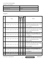
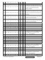
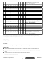
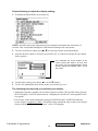
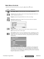
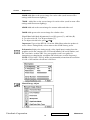
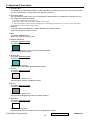
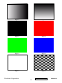
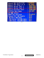
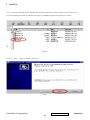
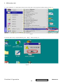
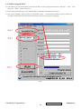
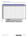
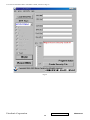
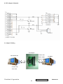
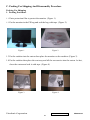
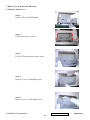
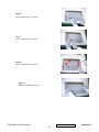
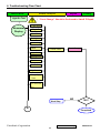
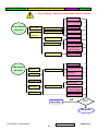
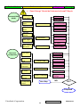
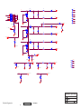
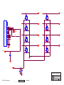
1
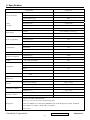
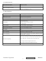
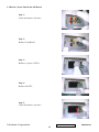
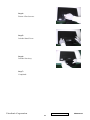
Service Manual ViewSonic VX2235wm-1 Model No. VS11349 22” Color TFT LCD Display (VX2235wm-1_SM Rev. 1a Aug. 2006) ViewSonic 381 Brea Canyon Road, Walnut, California 91789 USA - (800) 888-8583 Copyright Copyright © 2006 by ViewSonic Corporation. All rights reserved. No part of this publication may be reproduced, transmitted, transcribed, stored in a retrieval system, or translated into any language or computer language, in any form or by any means, electronic, mechanical, magnetic, optical, chemical, manual or otherwise, without the prior written permission of ViewSonic Corporation. Disclaimer ViewSonic makes no representations or warranties, either expressed or implied, with respect to the contents hereof and specifically disclaims any warranty of merchantability or fitness for any particular purpose. Further, ViewSonic reserves the right to revise this publication and to make changes from time to time in the contents hereof without obligation of ViewSonic to notify any person of such revision or changes. Trademarks Optiquest is a registered trademark of ViewSonic Corporation. ViewSonic is a registered trademark of ViewSonic Corporation. All other trademarks used within this document are the property of their respective owners. Revision History Revision SM Editing Date 1a 8/14/2006 ViewSonic Corporation ECR Number Description of Changes Initial Release J. Chang Confidential - Do Not Copy i Editor VX2235wm-1 TABLE OF CONTENTS 1. Precautions and Safety Notices 1 2. Specification 3 3. Front Panel Function Control Description 13 4. Circuit Description 19 5. Adjustment Procedure 20 6. Troubleshooting Flow Chart 54 7. Recommended Spare Parts List 62 8. Exploded Diagram and Exploded Parts List 64 9. Block Diagram 67 10. Schematic Diagrams 68 11. PCB Layout Diagrams 74 ViewSonic Corporation Confidential - Do Not Copy ii VX2235wm-1 1. Precautions and Safety Notices 1. Appropriate Operation (1) Turn off the product before cleaning. (2) Use only a dry soft cloth when cleaning the LCD panel surface. (3) Use a soft cloth soaked with mild detergent to clean the display housing. (4) Use only a high quality, safety approved AC/DC power cord. (5) Disconnect the power plug from the AC outlet if the product will not be used for a long period of time. (6) If smoke, abnormal noise, or strange odor is present, immediately switch the LCD display off. (7) Do not touch the LCD panel surface with sharp or hard objects. (8) Do not place heavy objects on the LCD display, video cable, or power cord. (9) Do not use abrasive cleaners, waxes or solvents for your cleaning. (10) Do not operate the product under the following conditions: - Extremely hot, cold or humid environment. - Areas containing excessive dust and dirt. - Near any appliance generating a strong magnetic field. - In direct sunlight. 2. Caution No modification of any circuit should be attempted. Service work should only be performed after you are thoroughly familiar with all of the following safety checks and servicing guidelines. 3. Safety Check Care should be taken while servicing this LCD display. Because of the high voltage used in the inverter circuit, the voltage is exposed in such areas as the associated transformer circuits. 4. LCD Module Handling Precautions 4.1 Handling Precautions (1) Since front polarizer is easily damaged, pay attention not to scratch it. (2) Be sure to turn off power supply when connecting or disconnecting input connector. (3) Wipe off water drops immediately. Long contact with water may cause discoloration or spots. (4) When the panel surface is soiled, wipe it with absorbent cotton or other soft cloth. (5) Since the panel is made of glass, it may break or crack if dropped or bumped on hard surface. (6) Since CMOS LSI is used in this module, take care of static electricity and ensure human earth when handling. (7) Do not open or modify the Module Assembly. (8) Do not press the reflector sheet at the back of the module in any direction. (9) In the event that a Module must be put back into the packing container slot after it was taken out of the container, do not press the center of the CCFL Reflector edge. Instead, press at the far ends of the CFL Reflector edge softly. Otherwise the TFT Module may be damaged. (10) At the insertion or removal of the Signal Interface Connector, be sure not to rotate or tilt the Interface Connector of the TFT Module. (11) After installation of the TFT Module into an enclosure (LCD monitor housing, for example), do not twist or bend the TFT Module even momentarily. When designing the enclosure, it should be taken into consideration that no bending/twisting forces may be applied to the TFT Module from outside. Otherwise the TFT Module may be damaged. (12) The cold cathode fluorescent lamp in the LCD contains a small amount of mercury. Please follow local ordinances or regulations for disposal. (13) The LCD module contains a small amount of materials having no flammability grade. The LCD module should be supplied with power that complies with the requirements of Limited Power Source (IEC60950 or UL1950), or an exemption should be applied for. (14) The LCD module is designed so that the CCFL in it is supplied by a Limited Current Circuit (IEC60950 or UL1950). Do not connect the CCFL to a Hazardous Voltage Circuit ViewSonic Corporation Confidential - Do Not Copy 1 VX2235wm-1 Correct methods : Only touch the metal-frame of the panel or the front cover of the monitor. Do not touch the surface of the polarizer . Incorrect Methods : Surface of the panel is pressed by fingers & this may cause “ MURA “ Take out the monitor with cushion Take out the monitor by grasping the LCD panel. That may cause “ MURA“. Place the monitor on a clean & soft foam pad . Place the monitor on foreign objects . That could scratch the surface of panel ViewSonic Corporation Confidential - Do Not Copy 2 VX2235wm-1 2. Specification 2.1 INSTRUCTION FEATURES VX2235wm Size 22 " wide TFTLCD PANEL Luminance (Typ) 280 cd/㎡ 1st Contrast Ratio (Typ) 700:1 Colors 16.2 M (6 bits + 2 bits FRC) CMO Response Time 5 ms(on/off) A220Z1 Viewing Angle (H/V) 170 ° / 160 ° Recommend resolution Input Signal Sync Compatibility Compatibility Power Voltage Power Consumption Audio Ergonomics OSD Control Dimension Weight Operating Condition Storage Condition 1680x1050@60Hz Analog Yes (75ohms, 0.7/1.0 Vp-p) Digital Yes Separate Sync Yes Composite Sync Yes Sync on Green Yes PC Yes Power Mac Yes TV Box (NextVision 6) Yes AC 100-240V, 50/60Hz Yes On Mode(Typ) < 48 W Off Mode (Max) ≦1 W 3W / THD 10% (Max) Yes Tilt ( 20 ° - -5 °) Yes Swivel No Pivot No Height Adjust No [ 1 ] [ 2 ] [ ][▼] [▲] Yes Physical (W x H x D) 524 x 482 x 244 mm Package (W x H x D) 575 x 522 x 150 mm Physical (Net Weight) 6 Kg / 13.2 lbs Package (Gross Weight) 7.5 Kg / 16.5 lbs Temperature (℉/℃) 41℉-95℉/+5℃-+35℃ Humidity (%) 20 % - 80 % Temperature (℉/℃) -4℉-131℉/-20℃-55℃ Humidity (%) 20 % - 85 % Global: CB, MPR II,WEEE,ROHS VSA:UL, cUL, FCC-B, TUV-S, NOM, Energy Star Regulation VSE:TUV/ERGO(covers ISO13406-2&MPR II),CE, GOST-R+Hygienic ,SASO , ENERGY VSI: BSMI, CCC, PSB, C-TICK, MIC, Green Mark VSCN:CCC ViewSonic Corporation Confidential - Do Not Copy 3 VX2235wm-1 2.2 GENERAL SPECTION Test Resolution & Frequency 1680x1050 @ 60Hz Test Image Size Full Size Contrast and Brightness Controls Factory Default: Contrast = 70%, Brightness = 100% 2.3 VIDEO INTERFACE Analog Input Connector DB-15 (Analog), refer the appendix A Digital Input Connector DVI-D (Digital), refer the appendix B Default Input Connector Defaults to the first detected input Video Cable Strain Relief Equal to twice the weight of the monitor for five minutes Video Cable Connector DB-15 Pin out Compliant DDC 1/2B 1. Video RGB (Analog) Video Signals Separate, Composite, and Sync on Green 2. TMDS (Digital) Video Impedance 75 Ohms (Analog), 100 Ohms (Digital) Maximum PC Video Signal 950 mV with no damage to monitor Maximum Mac Video Signal 1250 mV with no damage to monitor Sync Signals TTL DDC 1/2B Compliant with Revision 1.3 Sync Compatibility Separate Sync, Composite Sync, SOG Video Compatibility Shall be compatible with all PC type computers, Macintosh computers, and after market video cards 640 x 350*, 640 x 480, 720 x 400* (640 x 400*), 800 x 600, 832 x 624, 1024 x 768, 1152 x 864, 1152 x 870, 1280 x 720, 1280 x 960, 1280 x Resolution Compatibility 1024 , 1400 x 1050 , 1440 x 900 , 1600 x 1200, 1680 x 1050 * The image vertical size might not be full screen. But the image vertical position should be at the center. Exclusions ViewSonic Corporation Not compatible with interlaced video Confidential - Do Not Copy 4 VX2235wm-1 2.4 POWER SUPPLY Internal Power Supply Input Voltage Range Input Frequency Range Short Circuit Protection Over Current Protection Leakage Current Efficiency Fuse Power Dissipation Max Input AC Current Inrush Current (Cold Start) Power Supply Cold Start Power Supply Transient Immunity Power Supply Line Surge Immunity Power Supply Missing Cycle Immunity Power Supply Acoustics US Type Power Cable European Type Power Cable CCC Type Power Cable PSE Type Power Cable Power Saving Operation(Method) Power Consumption Recovery Time ViewSonic Corporation Part Number: 27-D009542 AC100~240 (Worldwide) 50 to 60 Hertz OUTPUT CAN BE SHORTED WITHOUT DAMAGE 3.3~4.5A typical at 5 VDC ( PROTECT WHEN SHORT CIRCUIT ) 3.5MA (MAX) AT 264VAC / 50HZ 80 % TYPICAL AT 115VAC FULL LOAD INTERNAL AND NOT USER REPLACEABLE < 48 WATTS (TYP) 1.6A (max) 80 A Max./ 240VAC / 50Hz (Cold Start at 25℃,Full Load) SHALL START AND FUNCTION PROPERLY WHEN UNDER FULL LOAD, WITH ALL COMBINATIONS OF INPUT VOLTAGE, INPUT FREQUENCY, AND OPERATING TEMPERATURE SHALL BE ABLE TO WITHSTAND AN ANSI/IEEE C62.41-1980 6000V 200 AMPERE RING WAVE TRANSIENT TEST WITH NO DAMAGE Shall be able to withstand 1.5 times nominal line voltage for one cycle with no damage Shall be able to function properly, without reset or visible screen artifacts, when ½ cycle of AC power is randomly missing at nominal input The power supply shall not produce audible noise that would be detectable by the user. Audible shall define to be in compliance with ISO 7779 (DIN EN27779:1991) Noise measurements of machines acoustics. Power Switch noise shall not be considered Separate 3-prong NEMA 5-15P type plug. Length = 1.8m. Connects to display. Color = Black Schuko CEE7-7 type plug. Length = 1.8m, Connects to display. Color = Black Separate 3-prong type plug. Length = 1.8m. Connects to display. Color = Black Separate 2-prong NEMA 1-15P type plug. Length = 1.8m. Connects to display. Color = Black VESA DPMS Signaling On Mode < 48 W (Typ) / 50 W (Max) Saving Mode < 2 W@230VAC 50HZ Off Mode < 1 W @230VAC 50Hz (DC Power Off; Meet to Energy Star Ver4.0 Tier2) On Mode = N/A, Active Off < 3 sec Confidential - Do Not Copy 5 VX2235wm-1 2.5 ELECTRICAL REQUIREMENT Horizontal / Vertical Frequency Horizontal Frequency 24 – 82 kHz Vertical Refresh Rate 50 – 85* Hz Maximum Pixel Clock 150 MHz Sync Polarity Independent of sync polarity. Timing Table SOG Composite Separated Item Timing Digital - TMDS Analog Remark For Analog sync, the image vertical size image 1 640 x 350 @ 70 Hz, 31.5 KHz will be not full screen (Still at the center), And the OSD will be 640x350/640x400/720x400 (primary= 720x400). For Analog sync, the image vertical size image 2 640 x 350 @ 85 Hz, 37.9 KHz will be not full screen (Still at the center), And the OSD will be 640x350/640x400/720x400 (primary= 720x400). For Analog sync, switch 640x400@60Hz and 3 640 x 400 @ 60 Hz, 31.5 KHz 640x480@60Hz by [1]+[2] short cut key (primary = 640x480@60Hz) For Analog sync, the image vertical size image 4 640 x 400 @ 70 Hz, 31.5 KHz will be not full screen (Still at the center), And the OSD will be 640x350/640x400/720x400 (primary= 720x400). For Analog sync, the image vertical size image 5 640 x 400 @ 85 Hz, 37.9 KHz will be not full screen (Still at the center), And the OSD will be 640x350/640x400/720x400 (primary= 720x400). 6 640 x 480 @ 50 Hz, 24.7 KHz For Analog sync, switch 640x400@60Hz and 7 640 x 480 @ 60 Hz, 31.5 KHz 640x480@60Hz by [1]+[2] short cut key (primary = 640x480@60Hz) 8 640 x 480 @ 67 Hz, KHz 9 640 x 480 @ 72 Hz, 37.9 KHz ViewSonic Corporation 35 Confidential - Do Not Copy 6 VX2235wm-1 10 640 x 480 @ 75 Hz, 37.5 KHz 11 640 x 480 @ 85 Hz, 43.3 KHz For Analog sync, the image vertical size image 12 720 x 400 @ 70 Hz, 31.5 KHz will be not full screen (Still at the center), And the OSD will be 640x350/640x400/720x400 (primary= 720x400). For Analog sync, the image vertical size image 13 720 x 400 @ 85 Hz, 37.9 KHz will be not full screen (Still at the center), And the OSD will be 640x350/640x400/720x400 (primary = 720x400). For Analog sync, the image vertical size image 14 720 x 480 @ 60 Hz, 31.5 KHz will be not full screen (Still at the center),and the information OSD shows 640x480 For Analog sync, the image vertical size image 15 720 x 576 @ 50 Hz, 31.3 KHz will be not full screen (Still at the center),and the information OSD shows 800x600 16 800 x 600 @ 56 Hz, 35.1 KHz 17 800 x 600 @ 60 Hz, 37.9 KHz 18 800 x 600 @ 72 Hz, 48.1 KHz 19 800 x 600 @ 75 Hz, 46.9 KHz 20 800 x 600 @ 85 Hz, 53.7 KHz 21 832 x 624 @ 75 Hz, 49.7 KHz For Analog sync, Switch 1024x768@50Hz and 22 1024 x 768 @ 50 Hz, 39.6 KHz 1280x768@50Hz by [1]+[2] short cut key (primary = 1024x768@50Hz) 23 1024 x 768 @ 60 Hz, 48.4 KHz 24 1024 x 768 @ 70 Hz, 56.5 KHz 25 1024 x 768 @ 75 Hz, KHz 26 1024 x 768 @ 75 Hz, 60.2 KHz 27 1024 x 768 @ 85 Hz, 68.7 KHz 28 1152 x 864 @ 75 Hz, 67.5 KHz 29 1152 x 870 @ 75 Hz, 68.7 KHz 60 For Analog sync, Switch 1024x768@50Hz and 30 1280 x 768 @ 50 Hz, 39.6 KHz 1280x768@50Hz by [1]+[2] short cut key (primary = 1024x768@50Hz) 31 1280 x 768 @ 60 Hz, 47.4 KHz 32 1280 x 768 @ 60 Hz, 47.8 KHz For Analog sync, Switch 1024x768@75Hz and 33 1280 x 768 @ 75 Hz, 60.3 KHz 1280x768@75Hz by [1]+[2] short cut key (primary = 1024x768@75Hz) 34 1280 x 768 @ 85 Hz, 68.6 KHz ViewSonic Corporation For Analog sync, Switch 1024x768@85Hz and Confidential - Do Not Copy 7 VX2235wm-1 1280x768@85Hz by [1]+[2] short cut key (primary = 1024x768@85Hz) 35 1280 x 960 @ 50 Hz, 49.4 KHz 36 1280 x 960 @ 60 Hz, 59.7 KHz 37 1280 x 960 @ 75 Hz, 75.2 KHz 38 1280 x 1024 @ 50 Hz, 52.7 KHz 39 1280 x 1024 @ 60 Hz, KHz 40 1280 x 1024 @ 70 Hz, 74.6 KHz 64 41 1280 x 1024 @ 72 Hz, 76.8 KHz KHz @ 60 Hz, 47.7 KHz 44 1400 x 1050 @ 50 Hz, 54.1 KHz 45 1400 x 1050 @ 60 Hz, 64.7 KHz 42 1280 x 1024 @ 75 Hz, 43 1360 x 768 80 For analog sync,, Switch 1400x1050@60Hz and 46 1400 x 1050 @ 60 Hz, 65.3 KHz 1680x1050@60Hz by [1]+[2] short cut key (primary = 1680x1050@60Hz) 47 1400 x 1050 @ 75 Hz, 82.3 KHz 48 1440 x 900 @ 60 Hz, 55.5 KHz 49 1440 x 900 @ 60 Hz, 59.9 KHz 50 1440 x 900 @ 75 Hz, 75 KHz 51 1600 x 1200 @ 60 Hz, 75 KHz For analog sync,, Switch 1400x1050@60Hz and 52 1680 x 1050 @ 60 Hz, 65.3 KHz 1680x1050@60Hz by [1]+[2] short cut key (primary = 1680x1050@60Hz) *1. Tolerance ≧ ±2KHz. (if the range dose not cover other timing mode) *2. Any timing not in the list, it should display as normal or show on “OUT OF RANGE” OSD message with blanking. *3. The image quality of 85Hz mode might be worse than 75Hz. Primary Presets 1680x1050 @ 60Hz User Presets Number of User Presets (recognized timings) Available: 10 presets total in FIFO configuration Changing Modes ● Maximum Mode Change Blank Time for image stability : 3 seconds (Max), excluding “Auto Image Adjust” time ● Under DOS mode (640 x 350, 720 x 400 & 640 x 400), it should recall factory setting when execute “Auto Image Adjust” ● The monitor needs to do “Auto Adjust” the first time when a new mode is detected (See section “0-Touch™ Function Actions”) ViewSonic Corporation Confidential - Do Not Copy 8 VX2235wm-1 2.6 FRONT PANEL CONTROLS AND INDICATORS Front Panel Hardware Controls Power Switch (Front Head) Power Control, soft Power Switch. Power LED (Front Head) Blue – ON Orange – Active Off Dark = Soft Power Switch OFF [ 1 ] BUTTON 1 [ 2 ] Button 2 Front Panel Controls (Head) [ 1 ] [ 2 ] [ ] [▼] [▲] [ ] Power [▼] DOWN ARROW BUTTON [▲] UP ARROW BUTTON Note: Power Button, Button 1 and Button 2 must be one-shot logic operation. (i.e. there should be no cycling) Reaction Time OSD must fully appear within 0.5s after pushing Button 1 Short Cuts Function from the button(s) [1] Main Menu [2] Input toggle (Analog or Digital) [▼] To immediately activate Brightness/Contrast menu. [▼] +[▲] [1] + [2] [1] + [▼] + [▲] Recall both of Contrast and Brightness to default Toggle 720x400 and 640x400 mode when input 720x400 or 640x400 mode White Balance. (Not shown on user’s guide) (Keep pushing 3 sec) [1] + [▼] Power Lock [1] + [▲] OSD Lock [▲] Essential mode switch Standard ->Text -> Cinema -> Game -> Portrait -> Scenery -> Vivid [2] + [▲] Skin tone switch Nature -> Reddish -> yellowish [▼] +[▲] + [ ] Factory Mode Remark : All the short cuts function are only available while OSD off ViewSonic Corporation Confidential - Do Not Copy 9 VX2235wm-1 Main Menu Controls Auto Image Adjust*1 Contrast/Brightness*2*4 Input Select Analog, Digital Audio Adjust Volume*4, Mute*4 Color Adjust SRGB, 9300K,7500K, 6500K(default), 5400,User Color [R, G, B] Information [H Frequency, V Frequency, Resolution, Pixel Clock, Serial Number, Model Number, [“www.ViewSonic.com” ] Manual Image Adjust Horizontal Size*1, H/V. Position*1, Fine Tune*1, Sharpness*3 , Opticolor [Standard, Text , Cinema, Game, Portrait, Scenery, Vivid ], Opticolor Skin Tone[Nature, reddish ,yellowish] Setup Menu Language [English, French, German, Italian, Spanish, Finnish, Japanese, Simplified Chinese, Traditional Chinese], Resolution Notice, OSD Position, OSD Timeout, OSD Background Memory Recall *1 These functions are not available in Digital Mode *2 These functions are not available under SRGB Mode, Opticolor On, and Opticolor Skin Tone On *3 These functions are not available under Native Resolution Mode *4 These functions setting can be recalled to default value by pressing [▼]+[▲] [Remark] Please refer to the detail in the Appendix C Function descriptions OSD Lock short cuts function for the buttons The OSD lock will be activated by pressing the front panel control buttons "(1), & (▲)" for 10 seconds. If the user then tries to access the OSD by pressing any of the buttons "1", "▼", "▲", "2" a message will appear on the screen for 3 seconds showing "OSD Locked". The OSD lock will be deactivated by pressing the front panel control buttons "(1), & (▲)" again for 10 seconds. Note1: When the OSD is locked will lock all functions, including “Volume” and “Mute” Note 2: Status bar indicating OSD Lock or Unlock is in progress and when complete it will indicate “OSD Locked” Note 3: OSD Lock should not lock Power Button and Power Lock function Power Lock short cuts function for the buttons The power button lock will be activated by pressing the front panel control buttons "(1), & (▼)" for 10 seconds. Locking the power button means that the user won't be able to turn off the LCD while the power button is locked. If the user presses the power button while it is locked, a message will appear on the screen for 3 seconds showing "Power Button Locked". It also means that with the power button locked, the LCD would automatically turn back "On" when power is restored after a power ViewSonic Corporation Confidential - Do Not Copy 10 VX2235wm-1 failure. If the power button is not in the locked mode, then power should return to it's previous state when power is restored after a power failure. The power button lock will be deactivated by pressing the front panel control buttons "(1), & (▼)" again for 10 seconds. Note 1: Status bar indicating Power Button lock or unlock is in progress and when complete it will indicate “Power Button Locked” Note 2: Power should only be lockable in the “On State” Memory Recall Actions Memory Recall action on the analog and digital mode as below 1. Set the factory defaults as shown in Section 4-8 2. Clean all the mode setting buffer 3. Execute Auto Image Adjust Note: Memory Recall should have no effect for Language, Power Lock, User Color Settings or Input Priority Resolution Notice Actions 1. Resolution Notice OSD should show on screen after changing to non-native mode for 30 sec 2. The OSD should disappear after 10 sec or by pushing button [1] or [2] Resolution Notice function should be disabled when push button [2] under Resolution Notice OSD 0-Touch™ Function Actions 1. Execute Auto Image Adjust when new mode detected, and save the settings to buffer for further use 2. It should be reset by Memory Recall function (Should not reset by power off, power unplug and others) OSD Auto Save The OSD shall save new settings when it is turned off by the user or when it times out. There shall not be a separate save Input Priority This function is defined the auto detect priority when the display has several inputs. Please refer to the detail flow chart as the appendix D ViewSonic Corporation Confidential - Do Not Copy 11 VX2235wm-1 2.7 AUDIO INTERFACE (SPEAKER SPECIFICATION) Line input signal 1.0 Vrms @1kHz Line input impedance 10 kOhm Maximum Amp power output (Watt) 2 W (RL=4Ω) Amp -THD < 10 % THD @1kHz Speaker Power rating(Ω/Watt) 4Ω/2.5 W (TYP.) ; 4Ω/ 3 W (MAX) Signal to Noise Ratio 72 dB Frequency response Fo – 20kHz SPL. 85 ± 3 dB (at 0.5m) FO 300 Hz Line input connection 3.5 mm stereo jacks There should be no audible vibration resonance at volume=100% & Vibration Screen image treble / bass in def. Value There should be no affect on the screen image stability under any conditions Connector PC99 requirement Audio in Lime Green pantone # 577C Cable type / length 3.5mm stereo cable / 1.8m length Audio DPMS SPEAKERS STAY ON WHEN THE REST OF THE MONITOR IS IN POWER SAVING NOTE: THERE IS NO GUARANTEE <1 W AT POWER CONSUMPTION IN ACTIVE OFF MODE, WHEN THE AUDIO CABLE IS CONNECTED ViewSonic Corporation Confidential - Do Not Copy 12 VX2235wm-1 3. Front Panel Function Control Description Adjusting the Screen Image Use the buttons on the front control panel to display and adjust the OSD controls which display on the screen. The OSD controls are explained at the top of the next page and are defined in “Main Menu Controls” on page 10. Main Menu with OSD controls Front Control Panel shown below in detail Standby Power On/Off Power light Blue = ON Orange = Power Saving Displays the control screen for the highlighted control. Also toggles between two controls on some screens. Also a shortcut to Auto Image Adjust. Scrolls through menu options and adjusts the displayed control. Also a shortcut to display the Contrast adjustment control screen (T) / OptiColor (S) Displays the Main Menu or exits the control screen and saves adjustments. ViewSonic Corporation Confidential - Do Not Copy 13 VX2235wm-1 Do the following to adjust the display setting: 1. To display the Main Menu, press button [1]. NOTE: All OSD menus and adjustment screens disappear automatically after about 15 seconds. This is adjustable through the OSD timeout setting in the setup menu. 2. To select a control to adjust, pressSorTto scroll up or down in the Main Menu. 3. After the desired control is selected, press button [2]. A control screen like the one shown below appears. The command line at the bottom of the control screen tells what to do next from this screen. You can toggle between control screens, adjust the selected option, or exit the screen. 4. To adjust the setting, press the up S or down T buttons. 5. To save the adjustments and exit the menu, press button [1] twice. The following tips may help you optimize your display: • Adjust the computer's graphics card so that it outputs a 1680 x 1050 @ 60Hz video signal to the LCD display. (Look for instructions on “changing the refresh rate” in the graphics card's user guide.) • If necessary, make small adjustments using H. POSITION and V. POSITION until the screen image is completely visible. (The black border around the edge of the screen should barely touch the illuminated “active area” of the LCD display.) ViewSonic Corporation Confidential - Do Not Copy 14 VX2235wm-1 Main Menu Controls Adjust the menu items shown below by using the up S and down T buttons. Control Explanation Auto Image Adjust sizes and centers the screen image automatically. Contrast adjusts the difference between the image background (black level) and the foreground (white level). Brightness adjusts background black level of the screen image. Input Select toggles between inputs if you have more than one computer connected to the VX2235wm. Audio Adjust Volume increases the volume, decreases the volume, and mutes the audio. Mute temporarily silences audio output. Color Adjust provides several color adjustment modes, including preset color temperatures and a User Color mode which allows independent adjustment of red (R), green (G), and blue (B). The factory setting for this product is 6500K (6500 Kelvin). sRGB-This is quickly becoming the industry standard for color management, with support being included in many of the latest applications. Enabling this setting allows the LCD display to more accurately display colors the way they were originally intended. Enabling the sRGB setting will cause the Contrast and Brightness adjustments to be disabled. ViewSonic Corporation Confidential - Do Not Copy 15 VX2235wm-1 Control Explanation 9300K-Adds blue to the screen image for cooler white (used in most office settings with fluorescent lighting). 7500K - Adds blue to the screen image for cooler white (used in most office settings with fluorescent lighting). 6500K-Adds red to the screen image for warmer white and richer red. 5400K-Adds green to the screen image for a darker color. User Color Individual adjustments for red (R), green (G), and blue (B). 1. To select color (R, G or B) press button [2]. 2. To adjust selected color, pressSandT. Important: If you select RECALL from the Main Menu when the product is set to a Preset Timing Mode, colors return to the 6500K factory preset. Information displays the timing mode (video signal input) coming from the graphics card in the computer, the LCD model number, the serial number, and the ViewSonic® website URL. See your graphics card’s user guide for instructions on changing the resolution and refresh rate (vertical frequency). NOTE: VESA 1680 x 1050 @ 60Hz (recommended) means that the resolution is 1680 x 1050 and the refresh rate is 60 Hertz. Manual Image Adjust ViewSonic Corporation Confidential - Do Not Copy 16 VX2235wm-1 Control Explanation Horizontal Size adjusts the width of the screen image. H./V. Position (Horizontal/Vertical Position) moves the screen image left or right and up or down. Fine Tune sharpens the focus by aligning text and/or graphics with pixel boundaries. NOTE: Try Auto Image Adjust first. Sharpness adjusts the clarity and focus of the screen image. OptiColor Mode provides an optimum display environment depending on the contents displayed. It contains 7 user-selectable presets. These 7 presets are easily accessible from the short cut keys. Standard is for general windows environment and monitor default setting. Text optimized for text editing and viewing in a word processing environment. Cinema optimized for movie and video environment. Game optimized for PC/TV game environment. Portrait optimized for displaying indoor portraits and enhancing pictures. Scenery optimized for displaying outdoor scenery images. Vivid optimized for color luster and sharpness. These 7 presets are carefully chosen by Viewsonic, but may not suit all users' tastes. In that case, the user can either return to the Standard setting and manually adjust the brightness and contrast as desired. OptiColor Skin Tone includes 3 presets (Natural / Red Tone / Yellow Tone) which user can select according to user's preference. ViewSonic Corporation Confidential - Do Not Copy 17 VX2235wm-1 Control Explanation Setup Menu displays the menu shown below: Language Select allows the user to choose the language used in the menus and control screens. Resolution Notice allows the user to enable or disable this notice. If you enable the Resolution Notice shown above and your computer is set at a resolution other than 1680 x 1050, the following screen appears. OSD Position allows the user to move the OSD menus and control screens. OSD Timeout sets the length of time the OSD screen is displayed. For example, with a “30 second” setting, if a control is not pushed within 30 seconds, the display screen disappears. OSD Background allows the user to turn the OSD background On or Off. Memory Recall returns the adjustments back to factory settings if the display is operating in a factory Preset Timing Mode listed in the Specifications of this manual. ViewSonic Corporation Confidential - Do Not Copy 18 VX2235wm-1 4. Circuit Description 1.RTD 2553V Realtek RTD2553V series products are all-in-one LCD monitor controllers supporting UXGA / WSXGA+ / WXGA+ / SXGA (optional), and integrate Realtek high performance ADC, TMDS Rx(optional),scaling engine, OSD engine, LVDS Tx, RSDS Tx and so on. Moreover, all products are pin compatible in QFP128-pin package to save cost and make the design easier. 2. RTD2120 This chip is the micro-processor of LCD monitor. It uses the design ware DW8051 of Synopsys as the 8051 core of this chip and is compatible with other industry 8051 series. Also, 96Kbyte FLASH with 8 bit bus is embedded in this chip which is licensed from TSMC 0.18um e-FLASH process. Here we use the package of PLCC44/LQFP48 if we would like to have a discrete MCU controller or we make a multi-chip package with our LCD monitor controller to form one chip package to save the cost of package and PCB material. ViewSonic Corporation Confidential - Do Not Copy 19 VX2235wm-1 5. Adjustment Procedure A. Function Test and Alignment Procedure 1. All Modes Reset You should do “All Model Reset” (Refer to Chap 3. Hot Keys for Function Controls) first. This action will allow you to erase all end-user’s settings and restore the factory defaults. 2. Auto Image Adjust The Auto Adjust is aimed to offer a best screen quality by built-in ASIC. For optimum screen quality, the user has to adjust each function manually. A.Turn the computer and LCD monitor on. B. Press the ‘Auto’ button on monitor keypad to Auto Adjust. C. The LCD monitor will start the Auto Adjust process automatically and run for 10 consecutive seconds, during which time you will notice the image change. 3. Firmware Test Patten: Burn in Model (Refer to Chap3. Hot Keys for Function Control) -Make sure the F/W is the latest version. 4. DCC Test Patten: EDID program -Make sure it can pass test program. 5. Window Shut Down Test Signal: 1280*1024@60Hz Test Pattern: Checkered Pattern Every One Pixel (50%Green & 50%Blue) Inspection Item: Flicker, Mura 6. Window BG Test Signal: 1280*1024@60Hz Test Pattern: Window standard pattern Inspection Item: Line Defect, Function Defect & Mura 7. 25 Gray Test Signal: 1280*1024@60Hz Test Pattern: Full Screen 25% White (Gray) Inspection Item: Particle, Line Defect & Mura 8. 50 Gray Test Signal: 1280*1024@60Hz Test Pattern: Full Screen 50% White (Gray) Inspection Item: Bright Dot, Particle, Line Defect & Mura 9. White Box Test Signal: 1280*1024@60Hz Test Pattern: Window standard pattern Inspection Item: Particle, Line Defect, Power, Image Remain & Mura ViewSonic Corporation Confidential - Do Not Copy 20 VX2235wm-1 10. Black Box Test Signal: 1280*1024@60Hz Test Pattern: Window standard pattern Inspection Item: Bright Dot, Line Defect & Power 11. RED Test Signal: 1280*1024@60Hz Test Pattern: Full Screen Red Inspection Item: Bright Dot, Partial & Line Defect 12. Green Test Signal: 1280*1024@60Hz Test Pattern: Full Screen Green Inspection Item: Bright Dot, Partial & Line Defect 13. Blue Test Signal: 1280*1024@60Hz Test Pattern: Full Screen Green Inspection Item: Bright Dot, Partial & Line Defect 14. Gray_Scale_0-100_V64 Test Signal: 1280*1024@60Hz Test Pattern: Vertical 64 (256) Gray Scale (Right → Left,From 0 to 100% White) Inspection Item: Line Defect & Function Defect 15. Function Test Display pattern Item 1 2 Pattern Gray_Scale_0-100_V Gray_Scale_0-100_H Description Vertical 64 (256) Gray Scale (right→left,From 0 to 100% White) Horizontal 64 (256) Gray Scale (up→down,From 0 to 100% White) Remark Figure 1 Figure 2 3 Black Full Screen Black Figure 3 4 Red Full Screen 50% Red Figure 4 5 Green Full Screen 50% Green Figure 5 6 Blue Full Screen 50% Blue Figure6 7 White Full Screen White Figure7 8 Black_Tile Black Tile Under White Background Figure 8 ViewSonic Corporation Confidential - Do Not Copy 21 VX2235wm-1 Figure 1 Figure 2 Figure 3 Figure 4 Figure 5 Figure 6 Figure 7 Figure 8 ViewSonic Corporation Confidential - Do Not Copy 22 VX2235wm-1 B BIOS update procedure 1. To setup ISP environment Hardware: PC or Notebook , Parallel(Printer) cable , ISP tool( Fig 1) Software: ISP driver . If the O.S. was Win2000 or Win XP please have to install PORT95NT.exe Fig1 In order to ensure can execute ISP program, please set BIOS in PC or Notebook as Fig 2 ViewSonic Corporation Confidential - Do Not Copy 23 VX2235wm-1 Fig 2 ViewSonic Corporation Confidential - Do Not Copy 24 VX2235wm-1 2. Install ISP 2.1 User could download ISP driver and PORT95NT install file from Myson Century website( //www.myson.com.tw ) 2.2 After extracting the zip file, the total files list as Fig 2.2, and double click the file of setup.exe to install. Fig 2.2 2.3 Press “Next" button to continue., see Fig 2.3 Fig 2.3 ViewSonic Corporation Confidential - Do Not Copy 25 VX2235wm-1 2.4 Keep default setting or press “Change" button for selecting the path that you want , and then press“Next"button to continue, see Fig 2.4. Fig 2 4 2.5 Press “Install" button to continue, see Fig 2.5 Fig 2.5 ViewSonic Corporation Confidential - Do Not Copy 26 VX2235wm-1 2.6 The Installer Information shows package warning, press “Ignore" button to continue, see Fig 2.6. Fig 2.6 2.7 Installation has finished, press “Finish" button, see Fig 2.7. Fig 2.7 ViewSonic Corporation Confidential - Do Not Copy 27 VX2235wm-1 3. ISP security code 3.1 After installation, we could find the shortcut in the setting path or the program bar (default setting), see Fig 3.1. Fig 3.1 2.2 Security file is a key to use ISP function, press “確定" button, see Fig 3.2. Fig 3.2 ViewSonic Corporation Confidential - Do Not Copy 28 VX2235wm-1 3.3 The warning is used to remind user of that different CPU rate may cause ISP function fail(it is limited by IIC protocol), press “確定" button, see Fig 3.3. Fig 3.3 2.4 Press“Create Security File" button to key in security code. Adjusting bar to decrease speed of IIC bus, see Fig 3.4. Fig 3.4 ViewSonic Corporation Confidential - Do Not Copy 29 VX2235wm-1 3.5 At least 2 Command No of security code, see Fig 3.5, and different security code between hardware ISP and software ISP. The security code of software ISP is set by user while coding, but the security code of hardware ISP is set by Myson Century. Fig 3.5 ViewSonic Corporation Confidential - Do Not Copy 30 VX2235wm-1 3.6 Fig 3.6 shows the setting for security code of hardware ISP, it needs 4 Command No, and key in command sequentially for 94, 94, AC, CA, 53. Fig 3.6 ViewSonic Corporation Confidential - Do Not Copy 31 VX2235wm-1 3.7 Fig 3.7 shows the setting for security code of software ISP, it needs 2 Command No, and key in command sequentially for 7C, 4C, 77. The Command No and command must be set by user while coding. About the detail of setting, please refer to Section 6 Boot code of ISP. Fig 3.7 ViewSonic Corporation Confidential - Do Not Copy 32 VX2235wm-1 4. Use ISP to program MCU 4.1 Select MTV type first, load the binary or Intel hex file that you want to program into the MCU, and select “Auto" item, then press “RUN" button, see Fig 4.1. 4.2 If user changes the MTV type, it must load file again, or the buffer of load file will be cleared. 4.3 CRC (cyclic redundancy check): the host can check CRC register's result instead of reading every byte in flash. The message of Check MCU CRC OK means that the Host verify ok for the progress of program. Fig 4.1 ViewSonic Corporation Confidential - Do Not Copy 33 VX2235wm-1 5 Use ISP to read MCU content 5.1 Only software ISP could read the MCU content, it is according to program the boot code while coding. The limitation is used for the security of customer's code. Select “Read Target" item, and press“RUN" button, the MCU content will show as Fig 5.1. Fig 5.1 ViewSonic Corporation Confidential - Do Not Copy 34 VX2235wm-1 5.2 If user uses hardware ISP to read MCU content, it shows as Fig 5.2. Fig 5.2 ViewSonic Corporation Confidential - Do Not Copy 35 VX2235wm-1 6 Re-entry the ISP Mode When you could not select or click `Reset MCU' button and enter ISP mode again, you refer the message as below: ViewSonic Corporation Confidential - Do Not Copy 36 VX2235wm-1 Note: (1)Disable the `Enter ISP Mode' option to avoid the error message display. (2)If you using the MTV312M64 or before MCU serials, the MCU will always in `ISP Mode'even programming fail or erase MCU that instead of select or press `Reset MCU'. ViewSonic Corporation Confidential - Do Not Copy 37 VX2235wm-1 7. Boot code of ISP 7.1 Hardware ISP (1) Without boot code (2) Fixed security code: 94, 94, AC, CA, 53 (3) Attention to the pin of HSCL (1) and HSDA (1) should keep in enable (4) MTV412M, MTV512M, CS8954 support hardware ISP 7.2 Software ISP (1) With boot code (2) User define the security code (3) Attention to the pin of HSCL (1) and HSDA (1) should keep in enable (4) Only software ISP could read the MCU content (5) MTV212M, MTV312M, MTV230M, MTV412M, MTV512M, CS8954 support software ISP 7.3 Boot code of software ISP (1) Initialize MCU (a) Define the I/O pin to HSCL (1) and HSDA (1) (b) Define the slave B address (c) Enable 8051 INT1 (ISR 2) (2) Coding for INT1 while get into ISP mode (a) Clear watchdog to prevent reset during ISP period (b) Disable all interrupt to prevent CPU wake-up (c) Write ISP slave address (d) Write 93h to ISP enable address to enable ISP (e) Enter 8051 idle mode ViewSonic Corporation Confidential - Do Not Copy 38 VX2235wm-1 7.4 The followings show the relationship between the code and the security code. ViewSonic Corporation Confidential - Do Not Copy 39 VX2235wm-1 8. ISP Adaptor Schematic 9. Adaptor Linking ISP Adaptor Connect with The Monitor Set Printer Cable PC/HOST 25Pins to 25Pins Connect with VGA Cable ViewSonic Corporation Confidential - Do Not Copy 40 VX2235wm-1 C. Packing For Shipping And Disassembly Procedure Packing For Shipping 1. Packing Procedure 1.1 Paste protection film to protect the monitor. (Figure 1) 1.2 Put the monitor in the PE bag and seal the bag with tape. (Figure 2) Figure 1 Figure 2 1.3 Put the cushion into the carton then place the monitor on the cushion. (Figure 3) 1.4 Put the cushion then place the seat assy and all the accessories into the carton. As last, close the carton and seal it with tape. (Figure 4) Figure 3 ViewSonic Corporation Figure 4 Confidential - Do Not Copy 41 VX2235wm-1 Monitor Assembly and Disassembly 1 Separate Stand Assy 1.1 Remove Stand Cover Step 1 : Remove the Seat Assy Step 2 : Remove the Stand Cover. Step 3 : Loose and remove 4 screws Step4 : Remove the Stand Assy Step 5 : Completed. ViewSonic Corporation Confidential - Do Not Copy 42 VX2235wm-1 2 Separate Rear Cover (Rear Case Assy) Separate Bezel hooks to take Bezel and Rear Cover apart. Step 1 : Loose and remove 2 screws. Step 2 : Separate Bezel hooks to take Bezel and Rear Cover apart. Step 3 : Remove Rear Cover. Step 4 : Completed. ViewSonic Corporation Confidential - Do Not Copy 43 VX2235wm-1 3 Remove Power Board and AD Board 3.1 Remove Metal Cover Step 1 : Remove FFC from OSD Board. Step 2 : Loose and remove 4 screws. Step 3 : Lift up LCD module and remove bezel. Step 4 : Remove 2 pieces of Backlight wires. Step 5 : Remove 2 pieces of Backlight wires. ViewSonic Corporation Confidential - Do Not Copy 44 VX2235wm-1 Step 6 : Loose and remove 2 screws. Step 7 : Loose and remove 2 screws. Step 8 : Loose and remove 4 screws. Step 9 : Remove the PCBA Cover ViewSonic Corporation Confidential - Do Not Copy 45 VX2235wm-1 3.2 Remove Power Board and AD Board Step 1 : Loose and remove 4 screws. Step 2 : Remove Lips Board Step 3 : Remove 2 pieces of FFCs. Step 4 : Remove the FFC. Step 5 : Loose and remove 4 screws. ViewSonic Corporation Confidential - Do Not Copy 46 VX2235wm-1 Step 6 : Remove AD PCBA. Step7 : Completed. 4 Change New AD Board and Power Board Step 1 : Place new AD Board. And fasten 4 fixed screws. Step 2 : Fasten 4 fixed screws. Step 3 : Insert FFC. Step 4 : Insert 2 pieces of FFCs . ViewSonic Corporation Confidential - Do Not Copy 47 VX2235wm-1 Step 5 : Insert new Lips Board. Step 6 : Fasten 4 fixed screws. Step 7 :Completed. ViewSonic Corporation Confidential - Do Not Copy 48 VX2235wm-1 5. Remove OSD Board Step 1 : Separate both Audio Cable. Step 2 : Take OSD Board apart. Step 3: Completed. ViewSonic Corporation Confidential - Do Not Copy 49 VX2235wm-1 6.Change New OSD Board Step 1 : Place New OSD Board. Step 2 : Insert Audio cable to connectors of New OSD Board. Step 3: Completed. 7. Add Cover to AD PCB Heatsink Step 1 : Join the PCB Cover. Step 2 : Fasten 4 fixed screws. ViewSonic Corporation Confidential - Do Not Copy 50 VX2235wm-1 Step 3 : Fasten 2 fixed screws Step 4 : Fasten 2 fixed screws. Step 5 : Insert 2 pieces of Backlight wires. Step 6 : Insert 2 pieces of Backlight. wires. Step 7 : Join LCD module and remove bezel. ViewSonic Corporation Confidential - Do Not Copy 51 VX2235wm-1 Step 8 : Fasten 4 fixed screws. Step 9 : Insert FFC. Step 10 : Completed. 8. Rear Assy & Stand Assembly Step 1 : Place Rear Cover. Step 2 : Fasten 2 fixed screws. Step 3 : Place the Stand Assy. ViewSonic Corporation Confidential - Do Not Copy 52 VX2235wm-1 Step 4 : Fasten 4 fixed screws. Step 5 : Join the Stand Cover. Step 6 : Join the Seat Assy Step 7 : Completed. ViewSonic Corporation Confidential - Do Not Copy 53 VX2235wm-1 6. Troubleshooting Flow Chart Defect Mode Failure Analysis Light On Test Repair Testing ※ “ Panel Change” Should be Performed to Level 3 Repair Flash Dots Abnormal Display Bright Dot Dark Dot Backlight Light Leakage Mura Check Panel Panel Change Image Sticking Brightness spot Particle Dot Defect Image Remain Group Bright Dots Others Cosmetics Defect Next Step NG A ViewSonic Corporation TEST Completed Confidential - Do Not Copy 54 VX2235wm-1 Defect Mode Failure Analysis Repair Testing ※ “ Panel Change” Should be Performed to Level 3 Repair A Display Noise Power on Check PCBA Display AD/B Change Power/B Change Abnormal Inverter/B Change Flicker CNT/B Change Beat Display Flicker Check Panel Panel Change Beat Display Shut Down AD/B Change Display Wave Check PCBA Power/B Change CNT/B Change No Backlight Check Panel Panel Change Check Adapter Adapter Change Next Step NG B ViewSonic Corporation TEST Completed Confidential - Do Not Copy 55 VX2235wm-1 Failure Analysis Repair Testing ※ “ Panel Change” Should be Performed to Level 3 Repair B Display White Out AD/B Change Check PCBA Power/B Change Booting Delay Check PCBA Inverter/B Change Brightness OSD/B Change Even Abnormal Power/B Change Check PCBA Inverter/B Change Beat Display No Backlight Panel Change Check Panel Check Adapter Adapter Change No signal AD/B Change R.G.B Check PCBA CNT/B Change Check Wire VGA cable Display Abnormal DVI cable Gray Scale Display Abnormal Check Panel Next Step Panel Change NG TEST C Completed ViewSonic Corporation Confidential - Do Not Copy 56 VX2235wm-1 Defect Mode Failure Analysis Repair Testing ※ “ Panel Change” Should be Performed to Level 3 Repair C Horizontal Line Defect Vertical Weak Line Check PCBA AD/B Change Check Panel Panel Change Horizontal Weak Line Vertical Band Defect Horizontal Band Defect Power Saving Display Check PCBA AD/B Change Abnormal AD/B Change Peculiar Smell Check PCBA Power/B Change Inverter/B Change Next Step NG TEST Complete ViewSonic Corporation Confidential - Do Not Copy 57 VX2235wm-1 Defect Mode Failure Analysis Repair Testing ※ “ Panel Change” Should be Performed to Level 3 Repair AD/B Change Power/B Change Power ON/OFF No Power Abnormal Turn Off Check PCBA Check PCBA CNT/B Change Inverter/B OSD/B Change Abnormal Check Wire Check Wire OSD Cable AC Power Change DC Power CNT Cable Change Check Adapter Adapter Change AD/B Change LED Display Abnormal LED Off Check PCBA Power/B Change Inverter/B LED Dark OSD/B Change LED Abnormal OSD Cable LED Loss Check Wire DC Power CNT Cable Change LED Flicker Adapter Change Next Step NG TEST Completed ViewSonic Corporation Confidential - Do Not Copy 58 VX2235wm-1 Defect Mode Failure Analysis Repair Testing ※ “ Panel Change” Should be Performed to Level 3 Repair Abnormal BIOS &OSD OSD Key AD/B Change Unavailable CNT/B Change OSD Can’t Input Check PCB Power/B Change Inverter/B OSD Can’t Read OSD/B Change OSD No D-sub cable Display OSD cable Check Wire OSD Jiggle VGA cable DVI cable OSD Display Abnormal Abnormal Check BIOS BIOS Update AD/B Change Voice Loss Loudspeaker CNT/B Change Abnormal Loud Power/B Change Check PCBA Inverter/B Change L/R Abnormal OSD/B Change Check Wire No Voice L/R Same OSD Cable Change Loudspeaker Check Loudspeaker Volume Loudspeaker Next Step Change NG Noise TEST Completed ViewSonic Corporation Confidential - Do Not Copy 59 VX2235wm-1 Defect Mode Failure Analysis Repair Testing ※ “ Panel Change” Should be Performed to Level 3 Repair Other Abnormal Display Shut Display Check PCBA Down AD/B Change Power/B Change CNT/B Change Check Panel Display Flicker Check PCBA ((tapping ) AD/B Change CNT/B Change Check Panel DVI Signal Panel Change Check PCB Panel Change AD/B Change Display Abnormal Check EDID Code Check PCBA TV Function Display Abnormal Check Wire Check Controller EDID Update TV /B Change AV Cable Change Remote controller Change Next Step NG TEST Complete ViewSonic Corporation Confidential - Do Not Copy 60 VX2235wm-1 Trouble Shooting Analysis Check the information in this section to see if the problems can be solved before requesting repair. Note:The consumers are only allowed to solve the problems described as below. Any unauthorized product modification, or failure to follow instructions supplied with the product will end the warranty immediately. z No image z No Signal Input z Use OSD Color Menu to adjust color setting. Dark area distorted z Use OSD Color Menu to adjust color setting. Color too dark z Use OSD Image Menu to adjust H_Position and V_Position. Check image size setting. Perform Auto Adjust. Uneven color z Use OSD Image Menu to adjust H_Position and V_Position. Check image size setting. Perform Auto Adjust. Size is not appropriate z Reset the LCD monitor Take off extra accessories (such as signal extension cord). Image is not centered z Check the signal connection between the computer and LCD monitor. Perform Auto Adjust. Distorted image z Adjust brightness and contrast by OSD. Irregular image z Adjust brightness and contrast by OSD. Image too dark z Adjust Phase. Image too bright z Check the computer image output resolution and frequency and compare the value with the preset values (Please refer to [Appendix-Display Mode]). Fuzzy Image z Check the signal connection between the computer and LCD monitor. “Out of Range” z Make sure power button is ON. Check whether the LCD monitor and computer power cords are plugged and whether there is a supply of power. Use OSD Color Menu to adjust color setting. White color is not white Use OSD Color Menu to adjust color setting. ViewSonic Corporation Confidential - Do Not Copy 61 VX2235wm-1 7. Recommended Spare Parts List RECOMMENDED SPARE PARTS LIST (VX2235wm-1) ViewSonic Model Number: VS11349 Serial No. Prefix: QA5 Item 1 2 3 4 5 6 7 8 9 10 11 12 13 14 15 16 17 18 19 20 21 22 23 24 25 26 27 28 29 30 31 Description Accessories: PC Board Assembly: Cabinets: Cables: Documentation: Hardware: Miscellaneous: Packing Material: Plastics: Rev: 1a ECR/ECN Power Cord Power Supply Board (Lips With Audio, V0.7) Main Board Rev.04 PCBA Rev.02,ODM Cover Hinge (Right) Cover Hinge (Left) Front Panel (Bezel) Back Cover Base Assembly (Stand Assy) Cover (Seat Assy) DVI Cable, S/L, 1.8M, W/2F Audio Cable (Accessory Black, 28AWG) Accessory Cable,D-Sub, 30AWG Flat Cable (FFC 36 Pins) Flat Cable (FFC 15 Pins) Safety Label 149 mmx29 mm Carton Label 76.2 mmx76.2 mm CD-Rom (Menu) SCREW,3,P=0.5 mm,L=4 mm SCREW,3,P=0.5 mm,L=4 mm Screw,M3*P0.5*6,Steel Screw, M4, P=0.7 mm, L=8 mm SCREW,4,P=0 mm,L=11.8 mm SCREW M3,P=0.5 mm,L=2.5 mm SCREW M3,P=1.27 mm,L=10 mm Tape,A170E1-H0P,900 mmx50 mmx0 mm PE Bag,600 mmx650 mmx0.13 mm Craft Foam (Top) Craft Foam (Bottom) Carft Box Panel Cover (Panel Protector Film) ViewSonic P/N A-00005071 B-00008026 B-00008027 B-00008028 C-00008039 C-00008040 C-00008041 C-00008042 C-00008043 C-00008044 CB-00002083 CB-00005678 CB-00005851 CB-00008014 CB-00008015 DC-00008038 DC-00008039 DC-00008040 HW-00000553 HW-00000553 HW-00000555 HW-00004042 HW-00006041 HW-00008002 HW-00008003 M-00000560 P-00008033 P-00008034 P-00008035 P-00008036 PL-00008008 Ref. P/N 32-D002330 27-D009542 35-D010627 35-D010238 40-D010946 40-D010960 40-D010959 40-D010948 40-D010942 40-D010947 32F0000004 32F2818011 32-D002132 32-D008479 32-D011077 77-D010937 77-D010936 76-D011105 42A9930008 42A9930008 42A9930014 42-D000649 42A9940007 42-D009237 42A9930015 7345511002 78-D009624 78-D011076 78-D011075 78-D011103 73-D009538 Location Universal number# Q'ty 1 1 1 1 1 1 1 1 1 1 1 1 1 2 1 1 1 1 13 2 6 1 4 3 1 0.05 1 1 1 1 1 Remark 1: Above listed items are examples, supplier can expand the rows to add more necessary items Remark 2: All revised RSPLs with newly added items or any change made should be highlighted and correlated with the ECN/ECR approved by ViewSonic Corporation. This is to eliminate repeated cross checks of each item between this version and prior versions. ViewSonic Corporation Confidential - Do Not Copy 62 VX2235wm-1 BOM LIST (VX2235wm-1) ViewSonic Model Number: VS11349 Rev: 1a Serial No. Prefix: QA5 Item ViewSonic P/N Ref. P/N Description Location ACF, COG, AC-8405Z-23 1.5mmX100M, 100000 mmx1.5 mm, Hitachi Chemical, COG-ACF, Green I Driver IC, COG, Scan, M170E5-L09, HX8653-A000PD400, 240/263/256Channel, Himax, (HX8633 36-D006411 shrank version), Green II L4M003XXXX 22"wide_TN, Photo Spacer , Corning 0.7mm Glass , Resin/BM(Panel Base) L4M003XXBI 22"wide_TN, Photo Spacer , Corning 0.7mm Glass , Resin/BM(Sheet Base) Polarizer, TFT, Degree 135, 478.16 mmx300.2 mmx0.215 mm, XT300CMM220Z1H0B, M220Z1, 74-D007599 LG Chem, LG HCR EWV Polarizer, CF, Degree 135, 480.76 mmx303.1 mmx0.215 mm, XT320CMM220Z1H0T, M220Z1, LG 74-D007598 Chem, LG HCR EWV Driver IC, COF, Data, M220Z1-L01, HX8019-A07BCBC5, COF, 6 bit, 642Channel, Himax, Green II 36-D007038 73-C000047 1 N/A 2 3 4 N/A N/A N/A 5 N/A 6 N/A 7 8 9 10 11 12 13 14 15 16 17 18 N/A N/A N/A N/A N/A HW-00008003 B-00008028 C-00008039 C-00008040 C-00008041 C-00008042 CB-00008015 19 HW-00000553 20 21 22 HW-00000555 C-00008043 PL-00008008 23 24 25 N/A DC-00008038 HW-00002076 77-D010937 7841595111 26 27 28 29 N/A DC-00000586 M-00000560 N/A 7741999141 7345511002 73-D001327 30 31 N/A P-00008033 78-D009624 32 33 34 DC-00008039 C-00008044 N/A 35 P-00008034 36 37 P-00008035 P-00008036 38 DC-00008040 39 HW-00000553 40 HW-00006041 41 42 43 44 45 46 HW-00004042 N/A N/A N/A CB-00008014 HW-00008002 47 B-00008026 48 B-00008027 49 N/A 50 N/A 51 52 53 N/A CB-00002083 CB-00005678 54 CB-00005851 55 A-00005071 73-D008216 73-D002676 35-D010045 7349951002 42A9930015 35-D010238 40-D010946 40-D010960 40-D010959 40-D010948 32-D011077 42A9930008 42A9930014 40-D010942 73-D009538 77-D010938 7841996911 78-D003113 77-D010936 40-D010947 79-D011065 78-D011076 78-D011075 78-D011103 76-D011105 42A9930008 42A9940007 42-D000649 41-D007402 44-D008027 41-D008024 32-D008479 42-D009237 27-D009542 35-D010627 10-D011770 10-D011769 10-D012223 32F0000004 32F2818011 32-D002132 32-D002330 ACF, COF, AC-4255U-16, 200000 mmx1.2 mm, Hitachi Chemical, Green II ACF, PCB, AC-9825R-35, 100000 mmx1.5 mm, Hitachi Chemical, PCB-ACF, Green I PCBA for , A220Z1-Z01-H, A220Z1-Z01-H-X, 1101-03, Rev.04, USI/ITC, ODM, Green II Silicone, TORAY/-9187L, 330g SCREW, M3, P=1.27 mm, L=10 mm, Pan Head, Phillips Cross Recess, Green I PCBA for , A220Z1-Z01-H, A220Z1-Z01-H-K2, 1101-02, Rev.02, USI/ITC, ODM, Green II Cover Hinge, A220Z1-H05, ABS PA-757N, ORIGINAL, Fuking, RIGHT, Green II Cover Hinge, A220Z1-H05, ABS PA-757N, ORIGINAL, Fuking, LEFT, Green II Bezel Assy, A220Z1-H05, Black(J01-J91A11B5), Fuking, SPK, Green II Rear Assy, A220Z1-H05, Silver(TY4818A)/Black(M1077), Fuking, audio_in+DVI-D, Green II FFC, FFC1DDX-A186S1A, 15 Pins, Tennsure_FFC, A220Z1-H05, Green II SCREW, 3, P=0.5 mm, L=4 mm, Pan Head, Phillips Cross Recess, Hama Naka Motogawa/Shin Yee/Hama Naka Shoukin/Shiho/Shye Ching, Green I SCREW, 3, P=0.5 mm, L=6 mm, Pan Head, Phillips Cross Recess, Hama Naka Shoukin/Shye Ching/Hama Naka Motogawa/Shin Yee, NA, Green I Stand Assy, A220Z1-H05, Silver(TY4818A), Hontech, Green II Panel Protector Film, A220Z1-H03, XG-536 T=0.1mm, Just Enter, BLANK SN Label for , A220Z1-H05, 50 mmx25 mm, Chang Huang/Kunshan Hwakuan, VSC_VX2235wm, Green II Safety Label for , A220Z1-H05, 149 mmx29 mm, Chang Huang, VSC_VX2235wm, Green II Corner Protector, paper, 50 mmx50 mmx1850 mm, Green II Separator, (AA), A190E2-H04, 1200 mmx1050 mmx11 mm, Shanghai Zhung Hao/Hua Sun Paper, ACER, Non Green Module Label, A190E2-H03, 75 mm, 40 mm, Non Green Tape, A170E1-H0P, 900 mmx50 mmx0 mm, Symbio, OPP Tape, 82296 mmx48 mmx0.045 mm, cmo, OPP, Green I Pallet, A190E3-H02_acer, Wooden, (KD-HT), 1209 mmx1066 mmx135 mm, Hua Sun Paper/Shanghai Hang Wei/Ming Li, Green I Bag, 600 mmx650 mmx0.13 mm, PE Foam, 650, Huang Jyii, Green II Carton Label for , A220Z1-H05, 76.2 mmx76.2 mm, Chang Huang/Kunshan Hwakuan, VSC_VX2235wm, Green II Seat Assy, A220Z1-H05, Black(ABS-757-J01)/Siliver(TY4818A), Hontech, Green II Shipping Package Information for , A220Z1-H05, VSC Cushion, A220Z1-H05, EPS, White, 565 mmx520 mmx75 mm, Li Ta, EPS-FORM(Top), Green II Cushion, A220Z1-H05, EPS, White, 565 mmx520 mmx65 mm, Li Ta, EPS-FORM(Bottom), Green II Carton, A220Z1-H05, 522 mmx154 mmx575 mm, Chen Yi Paper, VSC_VX2235wm, Green II MENU for A220Z1-H05, Complex, 4C, Yi Ching/Car Tong Kunshan, VSC_VX2235wm CD-ROM, Green II SCREW, 3, P=0.5 mm, L=4 mm, Pan Head, Phillips Cross Recess, Hama Naka Motogawa/Shin Yee/Hama Naka Shoukin/Shiho/Shye Ching, Green I SCREW, 4, P=0 mm, L=11.8 mm, Hexagon Stand Off, Socket, Hama Naka Motogawa/Shiho/Shin Yee/Shye Ching, Green I SCREW, M4, P=0.7 mm, L=8 mm, Round Head, Phillips Cross Recess, plate color Zn, Screw_with_Washer, Shye Ching/Hama Naka Motogawa, head D8, Green I Metal Frame Front, M220Z1-L01, SECC 0.6t, Fomgder/CLT_Metal, Green II Backlight Unit, A220Z1, Forhouse/ROE, Green II Cover AD Assy, A190A2, SECC, Jiin Ming, Left_Side 4 connector_VESA100*100, Green II FFC, CFC2128/862P060068D, 36 Pins, Tennsure/Hung Fu, AL foil, Green I SCREW, M3, P=0.5 mm, L=2.5 mm, Pan Head, Phillips Cross Recess, Shye Ching, Green II Lips With Audio, DAC-19M009 AF, 00 A, 5 V/3 A, 13.8 V0.7 A, I TYPE, 7 mA, 1710 V, Delta Dongguan_LIPS, Green II PCBA for , A220Z1-Z01-H, A170E2-E03-H-S6, 1101-02, Rev.04, ITC/USI, ODM, RTD2120S-LF, Green II Software (EDID_DVI), A220Z1, VSC591ED01, ViewSonic, Checksum(6A), VX2235wm, Digital Port, Green II Software (EDID_D-SUB), A220Z1, VSC591EA01, ViewSonic, Checksum(15), VX2235wm, Analog Port, Green II Software (BIOS), A220Z1, 22Z1LR3002, ViewSonic, Checksum(Bank1:0xEC, Bank2:0xD5), RSDS, RTD2120, Dual+Audio/Analog+Audio, Green II Accessory Cable, DVI, Black, Jceprocable, DVI-D(M) TO DVI-D(M), S/L, W/2F, Green I Accessory Cable, Audio, Black, Jhen Vei, A170E1-H01, 28AWG, Green I Accessory Cable, D-Sub, JV-4777, Black, Pins-Pins, Jhen Vei, 30AWG, Reduce Shield Rate, Green I Power Cord, LP-53 & VCTF 0.75mm^2 3C 6 BLACK & LS-13J, BLACK, BSMI, 1800 mm, Linetek, Green I ViewSonic Corporation Confidential - Do Not Copy 63 Universal number# Q'ty 0.0028 4 1 0.0833 1 1 8 0.0025 0.005 1 0.5 1 1 1 1 1 1 1 2 6 1 1 1 1 0.083 0.021 0.042 0.005 0.014 0.021 1 1 1 1 1 1 1 1 13 4 1 1 1 1 2 3 1 1 1 1 1 1 1 1 1 VX2235wm-1 8. Exploded Diagram and Exploded Parts List ViewSonic Corporation Confidential - Do Not Copy 64 VX2235wm-1 EXPLODED PARTS LIST (VX2235wm-1) ViewSViewSonic Model Number: VS11349 Rev: Rev: 1a SerialSerial No. Prefix: QA5 Item 1 2 3 4 5 6 7 8 9 10 11 12 13 14 15 16 17 18 19 20 21 22 ViewSonic P/N C-00008040 C-00008039 N/A N/A N/A N/A CB-00008015 C-00008043 C-00008044 N/A N/A N/A N/A N/A N/A HW-00008002 HW-00000553 HW-00004042 HW-00000553 N/A HW-00000555 HW-00008003 ViewSonic Corporation Ref. P/N 40-D010960 40-D010946 40-D010955 PM0ZFH0R00 40-D010955 35-D0110238 32-D011077 40-D010942 40-D010947 44-D009236 N/A 27-D008552 35-D009418 41-D008024 32-D009479 42-D009237 42A9930008 42-D000649 42A9930008 42A993008 42A9930014 42A9930015 Description COVER_HINGE_LEFT_22W15 COVER_HINGE_RIGHT_22W15 REAR_ASSY_22W15 22" Wide,Monitor,D-Sub+DVI+Audio BEZEL_ASSY_22W15 PCBA_A220Z1-Z01-H-K2 FFC_15pin STAND_ASSY_22W15 SEAT_ASSY_22W15 Backlight Unit,A220Z for MFM Maylar Lips Without Audio,DAC-19M009 BF PCBA for A220Z1-Z01-P Cover AD Assy FFC,36pin SCREW,M3,P=0.5mm,L=2.5mm,Pan Head SCREW,M3,P=0.5mm,L=4mm,Pan Head SCREW,M4,P=0.7mm,L=8mm,Round Head SCREW,M3,P=0.5mm,L=4mm,Pan Head SCREW,M3,P=0.5mm,L=5mm,Pan Head SCREW,M3,P=0.5mm,L=8mm,Pan Head SCREW,M3,P=1.27mm,L=10mm,Pan Head Confidential - Do Not Copy 65 Q'ty 1 1 1 1 1 1 1 1 1 1 1 1 1 1 2 3 7 1 4 2 6 1 VX2235wm-1 PACKING PART LIST ( VX2235wm-1 ) ViewSonic Model Number: VS11349 Rev: 1a Item 1 2 3 4 5 6 7 8 9 10 11 12 13 ViewSonic Corporation Confidential - Do Not Copy 66 VX2235wm-1 ViewSonic P/N N/A P-00008033 P-00008036 P-00008035 P-00008034 C-00008044 A-00005071 CB-00005851 CB-00005678 CB-00002083 DC-00008040 N/A N/A Ref. P/N VX2235wm 78-D009624 78-D011103 78-D011075 78-D011076 40-D010947 32-D002330 32-D002132 32F2818011 32F0000004 76-D011105 Different region (refer to BOM) Different region (refer to BOM) Location LCD Monitior PE Foam Bag Carton EPS Foam (Bottom) EPS Foam(Top) Seat Assy Power Cord Monitor Cable Audio Cable DVI Cable Menu (Quick Setup) Customer Label Warranty Registration card Q'ty 1 1 1 1 1 1 1 1 1 1 1 1 1 9. Block Diagram Speaker OSD Key Pad / Audio Out 3.3V 5V DVI-D Digital Video Main Board LCD Module 12V D-sub Analog Video Signal LDO DC-5V AC Power DC-12V LIPS Backlight Audio In ViewSonic Corporation Confidential - Do Not Copy 67 VX2235wm-1 ViewSonic Corporation 68 YOUT RESET_MCU DDC_DAT DDC_CLK DDC_DAT DDC_CLK Confidential - Do Not Copy DDC_DAT DDC_CLK B3 BUS_POEWR DDC2_SCL DDC2_SDA BUS_POEWR DDC2_SCL DDC2_SDA VX2235wm-1 02_DVI GNDB GNDG GNDR SOG BIN GIN RIN YOUT V18_ESD RESET_MCU RTD_SCSB RTD_SCLK VSYNC HSYNC RTD_SCSB RTD_SCLK GNDB GNDG GNDR SOG BIN GIN RIN RESET_RTD GNDB GNDG GNDR SOG BIN GIN RIN RTD_SCSB RTD_SCLK RX2P RX2N RX1P RX1N RX0P RX0N RXCP RXCN RTD_SDIO0 RTD_SDIO1 RTD_SDIO2 RTD_SDIO3 FR2P FR2N FR1P FR1N FR0P FR0N FG2P FG2N FG1P FG1N FG0P FG0N FB2P FB2N FB1P FB1N FB0P FB0N BR2P BR2N BR1P BR1N BR0P BR0N STB POL STV CKV OE VCM_PWM INV_ADJ VOL_ADJ GVOFF GVON FSTHI BSTHI RTD_SDIO0 RTD_SDIO1 RTD_SDIO2 RTD_SDIO3 BG2P BG2N BG1P BG1N BG0P BG0N RESET_RTD BB2P BB2N BB1P BB1N BB0P BB0N RESET_RTD VSYNC HSYNC RX2P RX2N RX1P RX1N RX0P RX0N RXCP RXCN 03_MCU BCKP BCKN FCKP FCKN PWR_SW PANEL_ON/OFF AUTO_ADJ SOURCE_SELECT KEY_UP KEY_DOWN MENU LED_ORG LED_GRN STB POL STV CKV OE VCM_PWM INV_ADJ VOL_ADJ GVOFF GVON FSTHI BSTHI FR2P FR2N FR1P FR1N FR0P FR0N FG2P FG2N FG1P FG1N FG0P FG0N FB2P FB2N FB1P FB1N FB0P FB0N BR2P BR2N BR1P BR1N BR0P BR0N BG2P BG2N BG1P BG1N BG0P BG0N BB2P BB2N BB1P BB1N BB0P BB0N BCKP BCKN FCKP FCKN PWR_SW PANEL_ON/OFF AUTO_ADJ SOURCE_SELECT KEY_UP KEY_DOWN MENU VSYNC HSYNC RX2P RX2N RX1P RX1N RX0P RX0N RXCP RXCN MUTE DCDC_ON/OFF AUDIO_FUNCTION INV_ON/OFF AUDIO_FUNCTION INV_ON/OFF LED_ORG LED_GRN DDC_CLK DDC_DAT CONNECT VGA_5V V33S DDC2_SDA DDC2_SCL BUS_POWER VGA_5V CONNECT V5A STB POL STV CKV OE VCM_PWM INV_ADJ VOL_ADJ GVOFF GVON FSTHI BSTHI FR2P FR2N FR1P FR1N FR0P FR0N FG2P FG2N FG1P FG1N FG0P FG0N FB2P FB2N FB1P FB1N FB0P FB0N BR2P BR2N BR1P BR1N BR0P BR0N BG2P BG2N BG1P BG1N BG0P BG0N BB2P BB2N BB1P BB1N BB0P BB0N BCKP BCKN FCKP FCKN PWR_SW PANEL_ON/OFF AUTO_ADJ SOURCE_SELECT KEY_UP KEY_DOWN MENU LED_ORG LED_GRN AUDIO_FUNCTION INV_ON/OFF MUTE DCDC_ON/OFF 10. Schematic Diagrams B5 V33S V5A 05_INTERFACE MUTE DCDC_ON/OFF MCU1 B4 RTD_SDIO0 RTD_SDIO1 RTD_SDIO2 RTD_SDIO3 04_SCALER V18_ESD YOUT RESET_MCU V33S B2 01_VGA V18_ESD CONNECT VGA_5V V33S V5A ViewSonic Corporation Model Title Date DIAGRAM Rev: FB1 RAI+ R1 1 C1 2 RIN TP1 3 RIN DDC_DAT 1 6 2 7 3 8 4 9 5 10 12 HSI VSI DDC_CLK 13 14 15 RAI+ 1 RIN TP2 TP TP3 TP TP4 TP TP5 TP TP6 TP TP7 TP 1 GNDR R2 C2 1 RAI- D1 1 SOG GAI+ GAIR3 BAI+ BAI- RAI- 2 11 TP 5 C3 1 GIN GNDR GNDR 5 1 GNDG C4 GND_POWER 1 BIN CON1 R5 R4 GND_POWER CA1 SOG SOG GND_POWER FB2 GAI+ 1 3 CONNECT C5 GIN 5 R7 R8 C6 1 V1 GNDB R6 2 GIN 4 1 5 D2 GND_POWER R9 2 GAI- C7 GNDG GNDG 5 BIN 5 GNDB 5 GND_POWER C8 4 VGA_5V 2 GND_POWER FB3 Z1 BAI+ R10 C9 2 3 1 1 BIN R11 C10 1 D3 GND_POWER R12 C11 2 BAI- GNDB C12 R13 V18_ESD 5 2 GND_POWER C13 1 Z2 GND_POWER GND_POWER TP8 R14 VSYNC 5 HSI R16 Z3 C14 Z4 R17 5 TP TP9 TP TP10 TP C15 1 1 R15 HSYNC L1 2 2 VSI GND_POWER TP11 GND_POWER GND_POWER DDC_CLK GND_POWER TP 1 HSYNC 1 VSYNC 1 DDC_CLK 1DDC_DAT GND_POWER GND_POWER DDC_CLK 4,5 DDC_DAT V2 DDC_DAT 4,5 V3 GND_POWER GND_POWER ViewSonic Corporation Model Title Date ViewSonic Corporation Confidential - Do Not Copy 69 VX2235wm-1 VGA Rev: RX0P RX0P 5 DATA0- D4 3 3 DATA0+ 1 RX1N RX1N 5 RX2N 5 RXCN 5 2 2 DATA1- 3 3 5 D7 1 1 4 2 DDC2_SDA C19 DATA2+ R18 RX2P RX2P 5 DATA2- D8 RX2N 3 DATA0+ DATA0DATA1+ DATA1DATA2+ DATA2- 4 2 C18 DDC2_SCL D9 1 1 C21 2 C20 CLK+ CLKCLK+ RXCP RXCP 5 CLK- RXCN 3 D10 GND_POWER D11 1 1 Z5 2 2 C23 2 C22 BUS_POEWR 1 4 RX1P D6 DDC2_SCL DDC2_SDA 11 3 19 22 18 17 10 9 2 1 13 12 5 4 21 20 23 24 RX1P 3 DAT0+ DAT0DAT1+ DAT1DAT2+ DAT2DAT3+ DAT3DAT4+ DAT4DAT5+ DAT5clk+ clk- DATA1+ 3 1/3shield 2/4shield 0/5shield clk shield 25 26 27 29 28 8 15 6 7 14 16 5 C17 2 R G B RGB GND HSYNC VSYNC SYNC GND DDC SCL DDC SDA +5V HPD RX0N 1 C16 CON2 RX0N D5 GND_POWER GND_POWER 5,6 V33S Z6 C24 ViewSonic Corporation GND_POWER Model Title Date ViewSonic Corporation 70 Confidential - Do Not Copy VX2235wm-1 DVI Rev: DDC_CI_5V DDC_CI_5V D12 VGA_5V 3 BUS_POWER 2 1 2 2 3 8 7 6 5 2 Q1 1 BUS_POWER 1 RP1 1 2 3 4 D13 U1 3 6 8 11 DDC2_SDA DDC2_SCL DDC_CLK DDC_DAT 1B 2B 3B 4B DDC_CI_5V 14 7 VCC GND D14 2 5 9 12 1A 2A 3A 4A DDC_CLK_OUT 6 V5A V5A 1 4 10 13 1OE 2OE 3OE 4OE D15 1 2 1 2 DDC_DAT_OUT DDC_CI_5V 1 3 3 2,5 2,5 R21 D16 R20 3 R19 2 C25 Q2 GND_POWER GND_POWER DDC_CI_SEL MCU_VCC 2 1 GND_POWER 3.1~3.6V RTD_SDIO0 5 RTD_SDIO1 5 RTD_SDIO2 5 RTD_SDIO3 5 1 2 3 4 2 C26 RESET_MCU 5 D17 6 PANEL_ON/OFF D18 Q3 1 2 3 4 3 1 + 1 2 3 4 R22 8 7 6 5 RP2 RP3 1 IICSCL IICSDA 2 1 2 RP4 8 7 6 5 R23 R24 R34 P10 P11 P12 P13 P14 P15 P16 P17 43 42 41 40 39 38 37 36 U2 BUS_POWER GND_POWER R36 R38 R39 RTD_SCSB 5 RTD_SCLK 5 V5A 1 VCC HSDA1/P3.1/TXD HSCL1/P3.0/RxD RTD_SCSB RTD_SCLK R26 D19 1 33 34 35 12 23 32 31 30 29 28 27 26 25 24 2 RST P1.0/ET2 P1.1 P1.2 P1.3 P1.4 P1.5 P1.6 P1.7 13 11 RST P31 P30 VSS DDC_DAT_OUT DDC_CLK_OUT R35 DDC_DAT DDC_CLK P3.2/INT0 P3.3/INT1 P3.4/T0 P3.5/T1 P7.6/CLKO2 P7.7 22 LED_GRN LED_ORG 2,5 2,5 14 15 16 17 18 19 VSS 6 6 R33 P32 P33 P34 P35 P76 P77 XTAL1 RESET_RTD 21 5 NC NC NC NC NC NC VSYNC P6.7 P6.6/CLOK1 P6.5 P6.4 P6.3/AD3 P6.2/AD2 P6.1/AD1 P6.0/AD0 X1 R29 R31 DDC_CI_SEL DA0/P5.0 DA1/P5.1 DA2/P5.2 DA3/P5.3 DA4/P5.4 DA5/P5.5 P5.6/HSCL2 P5.7/HSDA2 XTAL2 R27 2 3 4 5 6 7 8 9 20 R30 4 3 2 1 6 7 8 6 INV_ON/OFF 6 AUDIO_FUNCTION 2 CONNECT 6 MUTE 3 DDC2_SCL 3 DDC2_SDA X2 GND_POWER MCU_VCC P50 P51 P52 P53 P54 P55 P56 P57 VCC 2 5 RP5 10 R25 GND_POWER 1 44 GND_POWER Q4 8 7 6 5 3 6 DCDC_ON/OFF R32 P67 P66 P65 P64 P63 P62 P61 P60 MENU_ISP MENU 6 YOUT 5 KEY_DOWN 6 KEY_UP 6 SOURCE_SELECT AUTO_ADJ 6 PWR_SW 6 6 R37 Y1 MCU_VCC GND_POWER 2 R40 RST VCC 44 45 46 47 48 1 2 3 P30 P31 5 8 9 10 11 12 13 14 P10 P11 P12 P13 P14 P15 P16 P17 40 39 38 37 36 35 34 33 NC NC NC NC HSCL1/RXD/P3.0 HSDA1/TXD/P3.1 P3.2/INT0 P3.3/INT1 P3.4/T0 P3.5/T1 P7.6/CLKO2 P7.7 X2 X1 P32 P33 P34 P35 P76 P77 DA0/P5.0 DA1/P5.1 DA2/P5.2 DA3/P5.3 DA4/P5.4 DA5/P5.5 P5.6/HSCL2 P5.7/HSDA2 U4 NC/MTV512/RoHS VSS X2 X1 15 16 VSYNC P6.7 P6.6/CLKO1 P6.5 P6.4 P6.3/AD3 P6.2/AD2 P6.1/AD1 P6.0/AD0 32 31 30 29 28 27 26 25 24 23 22 21 20 P67 P66 P65 P64 P63 P62 P61 P60 NC NC GND_POWER P50 P51 P52 P53 P54 P55 P56 P57 42 43 GND_POWER P1.0/ET2 P1.1 P1.2 P1.3 P1.4 P1.5 P1.6 P1.7 IICSDA NC NC IICSCL 5 NC NC 6 18 19 SCL SDA 6 7 GND C27 7 RST A2 C29 8 VCC 4 VCC TEST VSS 3 A1 17 2 SEEPROM C28 GND_POWER A0 4 U3 1 41 R41 ViewSonic Corporation Model Title Date ViewSonic Corporation 71 Confidential - Do Not Copy VX2235wm-1 MCU Rev: Q5 4 3 YOUT 1 V33S XI 2 V33S V18C 1 2 1 2 V33S V33S FBS1 1 C30 C31 C32 C33 R42 FB5 3,6 FB4 2 R43 C35 C34 GND_POWER GND_POWER R45 6 VOL_ADJ R46 R47 PLL_TEST1 RX2P RX2N R49 RX1P RX1N R48 (PWM0) RX0P RX0N V33S 1 TMDS_V33 2 RXCP RXCN FB6 5 6 7 8 9 10 11 12 13 14 15 16 17 18 C37 TMDS_TST / PWM0 / TCON2 REXT TMDS_VDD RX2P RX2N TMDS_GND RX1P RX1N TMDS_VDD RX0P RX0N TMDS_GND RXCP RXCN 60 71 84 96 107 AR1N AR1P AR2N AR2P AR3N AR3P AG1N AG1P AG2N AG2P C36 2 FB7 30 31 32 33 34 35 36 37 38 39 40 C39 C38 2 2 RX2P RX2N RX1P RX1N RX0P RX0N RXCP RXCN GND_POWER AVS AHS VSYNC HSYNC 50 51 3 3 3 3 3 3 3 3 RX2P RX2N RX1P RX1N RX0P RX0N RXCP RXCN B1- / V7 B1+ / V6 G1- / V5 G1+ / V4 SOG1 / V3 R1- / V2 R1+ / V1 ADC_GND ADC_VDD AHS1 / V0 AVS1 / VCLK BR1N / TXE0BR1P / TXE0+ BR2N / TXE1BR2P / TXE1+ BR3N / TXE2BR3P / TXE2+ BG1N / TXECBG1P / TXEC+ BG2N / TXE3BG2P / TXE3+ PWM1 / TCON0 / COUT PWM2 / TCON1/TCON7 BJT_B BB3P/BBLU7 BB3N/BBLU6 BB2P/BBLU5 BB2N/BBLU4 BB1P/BBLU3 BB1N/BBLU2 BCLKP/BGRN7 BCLKN/BGRN6 BG3P/BGRN5 BG3N/BGRN4 1 V18_ESD 124 123 122 121 120 119 118 115 114 113 112 111 110 109 106 105 104 103 102 101 100 99 98 97 94 93 92 91 90 89 88 87 86 85 82 81 80 79 78 77 76 75 74 73 RTD_SCLK 4 RTD_SCSB 4 RTD_SDIO3 4 RTD_SDIO2 4 RTD_SDIO1 4 RTD_SDIO0 4 A_R0N A_R0P A_R1N A_R1P A_R2N A_R2P A_G0N A_G0P A_G1N A_G1P A_G2N A_G2P A_CKN A_CKP A_B0N A_B0P A_B1N A_B1P A_B2N A_B2P B_R0N B_R0P B_R1N B_R1P B_R2N B_R2P B_G0N B_G0P B_G1N B_G1P TCON9 TCON4 GVOFF GVON 6 6 TCON2 BSTHI 6 A_R0N A_R0P A_R1N A_R1P A_R2N A_R2P A_G0N A_G0P A_G1N A_G1P A_G2N A_G2P A_CKN A_CKP A_B0N A_B0P A_B1N A_B1P A_B2N A_B2P B_R1N B_R1P B_R2N B_R2P 2 2 2 2 2 2 2 RIN GIN BIN SOG GNDR GNDG GNDB R+ G+ B+ SOG RGB- 2,4 2,4 R50 DDC_CLK B_G2P R51 DDC_DAT TCON13 B_CKN POL TCON7 B_CKP 6 STB TCON11 B_B0N 6 STV TCON0 B_B0P 6 CKV TCON12 B_B1N 6 FSTHI 6 V33S B_G2N 6 OE B_B1P TCON3 B_B2N R75 R52 R53 6 2 6 R54 R55 PWM:230~300Hz(PWM1) B_G1N B_G1P B_G2N B_G2P B_CKN B_CKP B_B0N B_B0P B_B1N B_B1P B_B2P B_B2N B_B2P 4 GND_POWER BB2P BB2N 6 6 BB1P BB1N 6 6 BB0P BB0N 6 6 BG2P BG2N 6 6 BG1P BG1N 6 6 BG0P BG0N 6 6 BCKP BCKN 6 6 BR2P BR2N 6 6 BR1P BR1N 6 6 BR0P BR0N 6 6 FB2P FB2N 6 6 FB1P FB1N 6 6 FB0P FB0N 6 6 FG2P FG2N 6 6 FG1P FG1N 6 6 FG0P FG0N 6 6 FCKP FCKN 6 6 FR2P FR2N 6 6 FR1P FR1N 6 6 FR0P FR0N 6 6 PWM:47KHz(PWM2) ViewSonic Corporation BJT_B 2 3 VCM_PWM Q6 1 V18C INV_ADJ B_G0N B_G0P R44 4 RESET_MCU R74 B_R0N B_R0P 48 49 58 61 62 63 64 65 66 67 68 69 70 2 AG3N / TXO0AG3P / TXO0+ ACLKN / TXO1ACLKP / TXO1+ AB1N / TXO2AB1P / TXO2+ AB2N / TXOCAB2P / TXOC+ AB3N / TXO3AB3P / TXO3+ SDIO[0] / TCON13 SDIO[1] / TCON7 SDIO[2] / TCON11 SDIO[3] / TCON0 SCSB / TCON12 SCLK / TCON3 B+ BSOG G+ GR+ R- AVS0 AHS0 ADC_VDD ADC_GND B0+ B0SOG0 G0+ G0R0+ R0- DDCSCL1 / TCON4 DDCSDA1 / TCON9 19 20 21 22 23 24 25 26 27 28 29 52 53 54 55 56 57 AVS AHS GND_POWER RESET_RTD R28 33VRST_REF RESET_OUT TCON9 / PWM0 DDCSCL2 / VCLK / TCON4 DDCSDA2 / V7 / TCON6 SCLK / V6 / TCON3 SCSB / V5 / TCON7 SDIO[3] / V4 / TCON9 SDIO[2] / V3 / TCON5 SDIO[1] / V2 / TCON8 SDIO[0] / V1 / TCON10 V0 / TCON2 TCON13 / COUT 33VPNLOUT PLL_TEST2 TMDS_TEST PGND PGND PGND PGND PGND 59 72 83 95 108 XO XI DPLL_VDD DPLL_GND APLL_GND APLL_VDD PLL_TEST1 / TCON0 / TCON3 PLL_TEST2 / TCON1 / TCON12 PVCC PVCC PVCC PVCC PVCC 127 128 125 126 1 2 3 4 VCCK VCCK 46 117 GNDK GNDK GND_POWER XI 47 116 2.5V U5 Q14 1 3 Model Title Date ViewSonic Corporation 72 Confidential - Do Not Copy VX2235wm-1 SCALER Rev: TP12 V5A 1 5.0V V5A 3 V33D 1 VI(5V) 4 C41 VO(3.3V) VO(3.3V) (PANEL VCC) V33D 2 4 2 1 C44 B1 2 GND C40 1 F1 U6 TP 1 1 V12A TP V12V1 TP V5A1 V5A C42 C43 C45 C46 GND_POWER B2 1 2 GND_POWER CN3 AUDIOL+ AUDIOLAUDIOR+ AUDIOR- 1 2 3 4 5 6 7 8 9 10 11 12 13 14 15 16 R56 V5A AUDIO_DISABLE_INPUT MUTE_INPUT VOL_ADJ_INPUT 12V AUDIO_FUNCTION 4 R57 INV_ON/OFF_INPUT INV_ADJ_INPUT 2 V33S 3 1 Q8 3 R58 Q7 1 4 3 2 MUTE R59 Q9 TP13 1 4 V33S 2 INV_ON/OFF GND_POWER 2 B3 2 1 3 VI(5V) VO(3.3V) VO(3.3V) V33S 2 4 V33S 3,5 (SCALER VCC) 1 1 GND D20 GND_POWER 1 U7 TP C47 C48 C49 C50 V33S C51 V5A B4 1 2 1 2 1 2 B5 R60 R61 B6 GND_POWER R62 V12A 3 GND_POWER VR 3 [INV_GND] Q10 Q11 C52 + C54 1 VOL_ADJ C55 C53 5 2 INV_ADJ 2 5 1 GND_POWER GND_POWER GND_POWER V5A 4 PANEL_ON/OFF 4 DCDC_ON/OFF 5 VCM_PWM 5 GVOFF 5 GVON 5 MENU KEY_DOWN KEY_UP SOURCE_SELECT AUTO_ADJ LED_O LED_G PWR_SW 5 5 5 5 5 5 D C B A 15 14 13 12 11 10 9 8 7 6 5 4 3 2 1 MENU1 TP AUTO_ADJ1 TP BSTHI1 TP OE1 D C B A GVOFF1 TP TP 1 MENU KEY_DOWN1 TP 1 AUTO_ADJ PWR_SW1 TP 1BSTHI FSTHI1 TP 1 OE 1 GVOFF POL1 TP GVON1 TP 1 KEY_DOWN KEY_UP1 1PWR_SW 1 FSTHI 1 POL 1 GVON TP LED_O1 TP STV1 TP STB1 TP 1 KEY_UP 1 LED_O 1 STV TP14 CKV1 1 STB TP LED_G1 TP TP VCM_PWM1 TP 1 SOURCE_SELECT 1 LED_G 5 5 1 VCM_PWM GND_POWER BR0N BR0P BR1N BR1P BR2N BR2P BR0N BR0P BR1N BR1P BR2N BR2P BCKN BCKP BCKN BCKP 1 CKV CA CA 5 6 7 8 CP2 D C B A D C B A CP1 4 3 2 1 8 7 6 5 8 7 6 5 4 3 2 1 MENU KEY_DOWN KEY_UP SOURCE_SELECT AUTO_ADJ PWR_SW BSTHI BSTHI CN4 5 5 5 5 5 5 BG0N BG0P BG1N BG1P BG2N BG2P 5 5 5 5 5 5 BB0N BB0P BB1N BB1P BB2N BB2P BG0N BG0P BG1N BG1P BG2N BG2P BB0N BB0P BB1N BB1P BB2N BB2P 5 6 7 8 4 MENU 4 KEY_DOWN 4 KEY_UP 4 SOURCE_SELECT 4 AUTO_ADJ PWR_SW LED_G 4 LED_O AUDIORL3 AUDIOR+ L2 AUDIOLL5 AUDIOL+ L4 LP1 1 2 3 4 1 2 3 4 LP2 PANEL_ON/OFF DCDC_ON/OFF VCM_PWM GVOFF R63 GVON R64 1 2 3 4 5 6 7 8 9 10 11 12 13 14 15 16 17 18 19 20 21 22 23 24 25 26 27 28 29 30 31 32 33 34 35 36 1 2 3 4 5 6 7 8 9 10 11 12 13 14 15 16 17 18 19 20 21 22 23 24 25 26 27 28 29 30 31 32 33 34 35 36 CN1 GND_POWER GND_POWER V33D V33D 5 5 5 R70 POL STB 5 5 FCKN FCKP 2 5 5 1 4 Q12 LED_GRN R71 1 Q13 3 LED_ORG 3 4 5 5 5 5 5 5 V33S 2 V33S R73 R72 STV CKV OE STV CKV OE LED_G LED_O 5 FSTHI R69 R68 R65 FR0N FR0P FR1N FR1P FR2N FR2P FR0N FR0P FR1N FR1P FR2N FR2P POL STB R67 R66 FCKN FCKP 5 5 5 5 5 5 FG0N FG0P FG1N FG1P FG2N FG2P 5 5 5 5 5 5 FB0N FB0P FB1N FB1P FB2N FB2P FSTHI FG0N FG0P FG1N FG1P FG2N FG2P FB0N FB0P FB1N FB1P FB2N FB2P FSTHI 1 2 3 4 5 6 7 8 9 10 11 12 13 14 15 16 17 18 19 20 21 22 23 24 25 26 27 28 29 30 31 32 33 34 35 36 1 2 3 4 5 6 7 8 9 10 11 12 13 14 15 16 17 18 19 20 21 22 23 24 25 26 27 28 29 30 31 32 33 34 35 36 CN2 ViewSonic Corporation Model GND_POWER Title Date ViewSonic Corporation 73 Confidential - Do Not Copy VX2235wm-1 I/F Rev: 11. PCB Layout Diagrams ViewSonic Corporation Confidential - Do Not Copy 74 VX2235wm-1 ViewSonic Corporation Confidential - Do Not Copy 75 VX2235wm-1 ViewSonic Corporation Confidential - Do Not Copy 76 VX2235wm-1 * Reader’s Response* Dear Readers: Thank you in advance for your feedback on our Service Manual, which allows continuous improvement of our products. We would appreciate your completion of the Assessment Matrix below, for return to ViewSonic Corporation. Assessment A. What do you think about the content of this Service Manual? Unit Excellent Good Fair Bad 1. Precautions and Safety Notices 2. Specification 3. Front Panel Function Control Description 4. Circuit Description 5. Adjustment Procedure 6. Troubleshooting Flow Chart 7. Recommended Spare Parts List 8. Exploded Diagram and Exploded Parts List 9. Block Diagrams 10. Schematic Diagrams 11.PCB Layout Diagrams B. Are you satisfied with this Service Manual? Item Excellent Good Fair Bad 1. Service Manual Content 2. Service Manual Layout 3. The form and listing C. Do you have any other opinions or suggestions regarding this service manual? Reader’s basic dada: Name: Title: Company: Add: Tel: Fax: E-mail: After completing this form, please return it to ViewSonic Quality Assurance in the USA at facsimile 1-909-839-7943. You may also e-mail any suggestions to the Director, Quality Systems & Processes ([email protected]) ViewSonic Corporation Confidential - Do Not Copy 77 VX2235wm-1