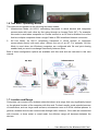
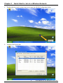
1
Wireless LAN Card
- Wireless PC Card (CardBus)
- Wireless Mini PCI Module
- Wireless PCI Adapter
IEEE 802.11b/g
User Manual
Rev. 1.0
May 2004
FCC Information to User
Model: Wireless PC Card
FCC ID: RC6AWP-914W
Model: Wireless Mini PCI Adapter
FCC ID: RC6AWI-922W
Model: Wireless PCI Adapter
FCC ID: RC6AWI-926W
FCC Caution
To assure continued compliance, any changes or modifications not expressly approved by the
party responsible for compliance could void the user’s authority to operate this equipment. This
device complies with Part 15 of the FCC Rules. Operation is subject to the following two
conditions:(1) this device may not cause harmful interference, and (2) this device must accept
any interference received, including interference that may cause undesired operation.
FCC Guidelines for Human Exposure
This equipment complies with FCC radiation exposure limits set forth for an uncontrolled
environment. This equipment should be installed and operated with minimum distance of 20 cm
between the radiator and your body. This transmitter must not be co-located or operating in
conjunction with any other antenna or transmitter.
Regulatory Compliance Information
This section includes user requirements for operating this product in accordance with National
laws for usage of radio spectrum and operation of radio devices. Failure of the end-user to
comply with the applicable requirements may result in unlawful operation and adverse action
against the end-user by the applicable National regulatory authority.
FCC Requirements for Operation in the United States
Radio Frequency Interference Warnings & Instructions
This equipment has been tested and found to comply with the limits for a Class B digital device,
pursuant to Part 15 of the FCC Rules. These limits are designed to provide reasonable
protection against harmful interference in a residential installation. This equipment uses and can
radiate radio frequency energy and, if not installed and used in accordance with the instructions,
may cause harmful interference to radio communications. However, there is no guarantee that
interference will not occur in a particular installation. If this equipment does cause harmful
interference to radio or television reception, which can be determined by turning the equipment
off and on, the user is encouraged to try to correct the interference by one or more of the
following methods:
1
User Manual for the Wireless LAN Card
• Reorient or relocate the receiving antenna
• Increase the separation between the equipment and the receiver
• Connect the equipment into an electrical outlet on a circuit different from that which the radio
receiver is connected
• Consult the dealer or an experienced radio/TV technician for help.
Modifications made to the product could void the user's right to operate the equipment.
Europe - EU Declaration of Conformity
This device is a 2.4 GHz low power RF device
intended for home and office use in EU and EFTA
member states. In some EU / EFTA member states
some restrictions may apply. Please contact local
spectrum management authorities for further details
before putting this device into operation.
Note: CE certificate is not applied for module.
R&TTE Compliance Statement
This equipment complies with all the requirements of DIRECTIVE 1999/5/CE OF THE
EUROPEAN PARLIAMENT AND THE COUNCIL of March 9, 1999 on radio equipment and
telecommunication terminal Equipment and the mutual recognition of their conformity (R&TTE).
The R&TTE Directive repeals and replaces in the directive 98/13/EEC (Telecommunications
Terminal Equipment and Satellite Earth Station Equipment) As of April 8, 2000.
Safety
This equipment is designed with the utmost care for the safety of those who install and use it.
However, special attention must be paid to the dangers of electric shock and static electricity
when working with electrical equipment. All guidelines of this and of the computer manufacture
must therefore be allowed at all times to ensure the safe use of the equipment.
Requirements For Operation in the European Community
Countries of Operation and Conditions of Use in the European Community
The user should run the utility program provided with this product to check the current channel
of operation and confirm that the device is operating in conformance with the spectrum usage
rules for European Community countries as described in this section. This device is intended to
be operated in all countries of the European Community.
Operation Using 2.4 GHz Channels in France
The following radio channel usage limitations apply in France.
The radio spectrum regulator in France, Autorité de regulation des telecommunications (ART),
enforces the following rules with respect to use of 2.4GHz spectrum in various locations in
2
User Manual for the Wireless LAN Card
France. Please check ART's web site for latest requirements for use of the 2.4GHz band in
France: http://www.art-telecom.fr/eng/index.htm.
When operating in the following metropolitan regions (départements) in France, this device may
be operated under the following conditions:
• Indoors using any channel in the 2.4-2.4835 GHz band (Channels 1-13)
• Outdoors using channels in the 2.4-2.454 GHz band (Channels 1-7)
When operating outside of the following regions (départements) in France such as Guadeloupe,
Martinique, St Pierre et Miquelon, Mayotte, this product can be operated under the following
conditions:
• Indoors using any channel in the 2.4-2.4835 GHz band (Channels 1-13)
• Outdoors using any channel in the 2.4-2.4835 GHz band (Channels 1-13)
When operating outside of the following regions (départements) in France such as Réunion and
Guyana, this product can be operated under the following conditions:
• Indoors using any channel in the 2.4-2.4835 GHz band (Channels 1-13)
• Outdoors using channels in the 2.420-2.4835 GHz band (Channels 3-13)
Please refer to the ART web site for further details.
Metropolitan Regions:
3
User Manual for the Wireless LAN Card
Table of Contents
Chapter 1 Introduction ............................................................................................................... 6
1.1 Preface ............................................................................................................... 6
1.2 Key Features ...................................................................................................... 6
1.3 Kit Contents........................................................................................................ 6
1.4 System Requirements ........................................................................................ 6
1.5 LED Definition .................................................................................................... 6
1.6 Two Basic Operating Modes .............................................................................. 7
1.7 Location and Range ........................................................................................... 7
Chapter 2 Basic Installation....................................................................................................... 8
2.1 Install the Wireless LAN Card............................................................................. 8
2.2 Install the Driver and Software Utility.................................................................. 8
2.3 Uninstall the Driver and Software Utility ........................................................... 10
Chapter 3 Quick Start to Join in a Wireless Network ............................................................... 13
Chapter 4 Software Utility - WLAN Configuration Utility .......................................................... 15
4.1 Overview .......................................................................................................... 15
4.2 Profiles Tab ...................................................................................................... 15
4.2.1 Profiles List Section................................................................................ 15
4.2.2 Buttons ................................................................................................... 16
4.2.3 Icon ........................................................................................................ 16
4.3 Link Status Tab ................................................................................................ 16
4.4 Site Survey Tab................................................................................................ 17
4.4.1 Site Section ............................................................................................ 17
4.4.2 Buttons ................................................................................................... 17
4.4.3 Icons....................................................................................................... 17
4.5 Statistics Tab.................................................................................................... 18
4.5.1 Transmit Statistics Section ..................................................................... 18
4.5.2 Receive Statistics Section ...................................................................... 18
4.5.3 Button..................................................................................................... 18
4.6 Advance Tab .................................................................................................... 19
4.6.1 Drop Menu Section................................................................................. 19
4.6.2 Checkbox Section .................................................................................. 19
4.6.3 Icons & Buttons Section ......................................................................... 19
4.7 About Tab......................................................................................................... 20
4.8 Add Profile....................................................................................................... 21
4.8.1 Configuration Tab................................................................................... 21
4.8.2 Authentication & Security Tab ................................................................ 22
Chapter 5 Configuration .......................................................................................................... 26
5.1 Connect to an Access Point in Infrastructure Mode.......................................... 26
5.2 Connect to an Ad Hoc Station .......................................................................... 27
5.3 Start a New Ad Hoc Wireless Network ............................................................. 29
4
User Manual for the Wireless LAN Card
Chapter 6
Chapter 7
Activate the Software AP Function ......................................................................... 31
6.1 Introduction....................................................................................................... 31
6.2 Bridge Connections .......................................................................................... 31
Software Utility - WLAN SoftAP Configuration Utility .............................................. 33
7.1 Overview .......................................................................................................... 33
7.2 Config Tab........................................................................................................ 34
7.2.1 Config Tab.............................................................................................. 34
7.2.2 Security Button ....................................................................................... 35
7.3 Access Control Tab .......................................................................................... 36
7.4 WDS Tab.......................................................................................................... 37
7.5 MAC Table Tab ................................................................................................ 38
7.6 Event Log Tab .................................................................................................. 38
7.7 Statistics Tab.................................................................................................... 39
7.7.1 Transmit Statistics Section ..................................................................... 39
7.7.2 Receive Statistics Section ...................................................................... 39
7.7.3 Button..................................................................................................... 39
7.8 About Tab........................................................................................................ 40
Chapter 8 Troubleshooting ...................................................................................................... 41
5
User Manual for the Wireless LAN Card
Chapter 1 Introduction
1.1 Preface
The Wireless LAN Card frees you from traditional Ethernet wiring and helps you connect to an
existing wireless network for sharing your broadband cable or DSL Internet access. It is
designed for computers running Microsoft® Windows® 98SE, ME, 2000 and XP operating
systems. Its auto-sensing capability allows high packet transfer at up to 54 Mbps for maximum
throughput or dynamic range shifting to lower speeds due to distance or operating limitations in
an environment with a lot of electromagnetic interference. The power saving capability
eliminates from wasting power especially in Laptop PC. This card complies with 2.4GHz IEEE
802.11b/g standards and can protect data integrity with enterprise-level WPA security. With the
additional software AP function, you can easily convert your PC into an Access Point virtually.
You can setup this card as a Client Station or an Access Point via a powerful WLAN
management software utility stored in the packaged CD. This accommodating dual-functionality
makes it your best choice to cooperate with a PC with no cabling hassle.
1.2 Key Features
•Operate at 2.4GHz unlicensed frequency with data transmission rate up to 54Mbps
•IEEE standards support: IEEE 802.11b, 802.11g
•Advanced security features including WEP, WPA
•32-bit CardBus / Mini PCI type IIIB / 32-bit PCI Rev. 2.2 interface
•Full-featured WLAN management software utility
•Compatible with Windows 98SE, ME, 2000 and XP
1.3 Kit Contents
•Wireless LAN Card (PC Card (CardBus) / Mini PCI Module / PCI Adapter)
•Set-up CD with user manual & software utility
1.4 System Requirements
A computer must be at least equipped with the following requirements:
•available PC Card slot / Mini PCI slot / PCI slot
•CD-ROM drive
•Microsoft® Windows® 98SE, ME, 2000 or XP operating system
•Pentium® II 450MHz or faster processor
•64 Mbytes RAM
•50 Mbytes free hard disk space
1.5 LED Definition
•Ready: lit when the card is plugged in and ready to transmit or receive
•Link/Act: lit when the card is wirelessly connected; flash when it is transmitting or receiving
Note: Mini PCI Module has no LED indicators; PCI Adapter only has Link/Act LED.
6
User Manual for the Wireless LAN Card
1.6 Two Basic Operating Modes
This card can be operated in the following two basic modes:
1. Infrastructure Mode: An 802.11 networking framework in which devices and computers
communicate with each other by first going through an Access Point (AP). For example,
this mode is used when computers in a house connect to an AP that is attached to a router
that lets multiple computers share a single Cable or DSL broadband Internet connection.
2. Ad Hoc Mode: An 802.11 networking framework in which devices or computers
communicate directly with each other, without the use of an AP. For example, Ad Hoc
Mode is used when two Windows computers are configured with file and print sharing
enabled and you want to exchange files directly between them.
Both of these configuration options are available with this card and are instructed in this user
manual.
1.7 Location and Range
Computers can connect over wireless networks indoors at a range that vary significantly based
on the physical location of the computer with this card. For best results, avoid potential sources
of interference, such as: large metal surfaces, microwaves ovens or 2.4GHz cordless phones. In
general, wireless devices can communicate through walls. However, if the walls are constructed
with concrete, or have metal, or metal mesh, the effective range will decrease between the
devices.
7
User Manual for the Wireless LAN Card
Chapter 2 Basic Installation
2.1 Install the Wireless LAN Card
1.
2.
Make sure this card is firmly installed in your PC.
Turn on your PC and log in the operating system.
2.2 Install the Driver and Software Utility
1.
Click “Cancel” to close the Find New Hardware diagram. Insert the packaged CD into your
CD-ROM drive. The CD will automatically start to install the driver and utility into your PC.
2.
Click “Yes” to proceed the WLAN Utility installation.
8
User Manual for the Wireless LAN Card
3.
Click “Finish” and the utility shortcut will appear on your desktop after a little while. Double
click this shortcut.
4.
For Windows XP users, you will be asked to select the software utility installed or the
Windows XP Wireless Zero Configuration. This manual instructs the former. (For better
usage, please make sure that your Windows XP operating system has been installed
Windows XP Service Pack 1a and Windows XP Support Patch for Wi-Fi Protected Access.)
9
User Manual for the Wireless LAN Card
5.
You will see this card’s system tray icon on the lower right portion of the Windows task bar.
2.3 Uninstall the Driver and Software Utility
1.
Open Control Panel.
10
User Manual for the Wireless LAN Card
2.
Double click Add or Remove Programs.
3.
Select the Wireless LAN Card from the list.
11
User Manual for the Wireless LAN Card
4.
Click the Change/Remove button.
5.
Select Yes, I want to restart my computer now., and then click Finish.
12
User Manual for the Wireless LAN Card
Chapter 3 Quick Start to Join in a Wireless Network
1.
Double click the card’s system tray icon to open the WLAN Configuration Utility.
2.
Click the Site Survey tab.
13
User Manual for the Wireless LAN Card
3.
This card will auto-select the best wireless network to connect. You can also select one
network with strongest signal and no security, and click the Connect button. A Connected
icon will appear when the card is linked to the selected network.
4.
Refer to Chapter 5 Configuration for more configuration details.
14
User Manual for the Wireless LAN Card
Chapter 4 Software Utility - WLAN Configuration Utility
4.1 Overview
•
•
•
•
•
•
Profiles: A set of preset system parameters, or “snapshots”, of the available APs within a
wireless network. You can record these “snapshots”. After this card is connected to an AP,
you can save the system parameters as these specific profiles. It significantly minimizes
access time to the same wireless network while this card is initializing.
Link Status: A status screen that tells you information of this card and link condition of the
current network.
Site Survey: Initiate a survey of the current available wireless networks and display these
APs, the Ad Hoc stations, and their associated information.
Statistics: Monitor the card's current traffic activity when connected to a wireless network.
Advance: Configure advanced operation parameters and display extra options. Note that
some options are not supported currently.
About: Hardware information of this card and its software elements.
4.2 Profiles Tab
4.2.1 Profiles List Section
• Profile Name: List all profiles you named.
• SSID: The specific name of each AP or Ad Hoc station in your profiles.
• Channel: Current channel adopted by this network.
• Authentication: The authentication type adopted by each AP or Ad Hoc station.
15
User Manual for the Wireless LAN Card
•
•
Encryption: The encryption type adopted by each AP or Ad Hoc station.
Network Type: Infrastructure mode or Ad Hoc mode.
4.2.2 Buttons
• Add: Define a new profile. Refer to 4.8 Profile.
• Delete: Delete a profile.
• Edit: Alter an existing profile.
• Activate: Connect the card to the selected network.
4.2.3 Icon
•
Connected: Connection built with this specified network.
•
Disconnected: Fail to build connection with this specified network.
4.3 Link Status Tab
•
•
•
•
•
•
Status: SSID and BSSID of the currently connected network.
Current Channel: Current channel and its corresponding frequency.
Link Speed (Mbps): The data transfer speed adopted by this network (measured in Mbits
per second).
Throughput (Kbps): Current transmit rate (TX) and receive rate (RX) (measured in Kbits per
second).
Link Quality: Throughput Level where 100% equals the maximum connection quality.
Signal Strength: The receive signal strength level. Check the dBm checkbox to display in
16
User Manual for the Wireless LAN Card
•
dBm format.
Noise Level: Current interference level where 0% equals the best connection quality.
4.4 Site Survey Tab
4.4.1 Site Section
• SSID: The name of each AP or Ad Hoc station.
•
•
•
•
•
•
BSSID: The MAC address of SSID.
Signal: Indicate each associated network’s link quality measured in percentage.
Channel: Current channel adopted by this network.
Encryption: The encryption type adopted by each AP or Ad Hoc station.
Authentication: The authentication type adopted by each AP or Ad Hoc station.
Network Type: Infrastructure mode or Ad Hoc mode.
4.4.2 Buttons
• Rescan: Update associated networks.
• Connect: Connect to the selected network.
• Add to Profile: Save the selected network connection status into a profile. Refer to 4.8 Add
Profile.
4.4.3 Icons
•
Connected: Connection built with this specified network. A status bar on the left-bottom
side of the window will show the connected SSID.
17
User Manual for the Wireless LAN Card
4.5 Statistics Tab
4.5.1 Transmit Statistics Section
• Frames Transmitted Successfully: The number of successfully transmitted frames.
•
•
•
•
•
Frames Transmitted Successfully without Retry: The number of successfully transmitted
frames without any retry.
Frames Transmitted Successfully after Retry: The number of successfully transmitted
frames with one or more retries.
Frames Fail to Receive ACK After all Retries: The number of unsuccessfully transmitted
frame with many retries.
RTS Frames Successfully Receive CTS: The number of successfully received the CTS
(Clear To Send) response after this card sends out the RTS (Request To Send) message.
RTS Frames Fail to Receive CTS: The number of unsuccessfully received the CTS
response after this card sends out the RTS message.
4.5.2 Receive Statistics Section
• Frames Received Successfully: The number of successfully received frames.
• Frames Received with CRC Error: The number of received frames with CRC (Cyclical
Redundancy Checking) error.
•
•
Frames Dropped due to Out-of-Resource: The number of dropped frames.
Duplicate Frames Received: The number of duplicate frames.
4.5.3 Button
• Reset Counter: Restart the displayed statistics.
18
User Manual for the Wireless LAN Card
4.6 Advance Tab
4.6.1 Drop Menu Section
• Wireless mode: Choose 802.11b only mode or 802.11b/g mix mode.
•
•
•
Ad Hoc mode: When starting Ad Hoc network, you can specify 802.11b only mode or
802.11b/g mix mode.
802.11b/g Protection: 802.11b uses CCK modulation and 802.11g uses CCK–compatible
OFDM modulation. Enable this to prevent the data collision in the concurrent 802.11b/g
network. Auto (auto-detect) selection is recommended.
Tx Rate: The selected link rate.
4.6.2 Checkbox Section
• Tx BURST: Check to enable the card to transmit more data in a frame interval.
• Tx turbo rate: Enhance the data rate transmitted up to 72/100Mbps. This checkbox is
currently disabled.
• Use short slot time: Enhance the data rate with Short Slot Time mechanism. This checkbox
is currently disabled.
4.6.3 Icons & Buttons Section
•
Radio On: Enable radio transmission.
•
•
Radio Off: Disable radio transmission.
Apply: Confirm your settings.
19
User Manual for the Wireless LAN Card
4.7 About Tab
•
•
•
•
Utility Version: Version and released date of this card’s utility.
Driver Version: Version and released date of this card’s driver.
EEPROM Version: Version of this card’s firmware.
MAC Address: MAC address of this card.
20
User Manual for the Wireless LAN Card
4.8 Add Profile
4.8.1 Configuration Tab
• Profile Name: Specify a name for this profile.
•
•
•
•
•
•
•
SSID: Specify a network name identified in the wireless network.
Power Saving Mode: Select one power save scheme from CAM (Constantly Awake Mode)
(No power save option adopted by the card.) and Power Saving Mode (Power Save option
adopted by the card). Check Use Constantly Awake Mode when AC Power is used as long
as your PC uses external power supply. This setting will affect the battery life of the host of
the card.
Network Type: Select Infrastructure mode or Ad Hoc mode adopted by this network.
TX Power: Select the transmit power of this card. 100% is recommended.
Preamble: Select the length of the CRC block for communication between the AP and this
card. Make sure to select the appropriate preamble type the same as AP’s. High network
traffic areas should use the shorter preamble type. Auto (follow AP’s preamble type)
selection is recommended. This field is supported only in Infrastructure mode and currently
disabled.
RTS Threshold: Designed to prevent the Hidden Node issue, a problem happens in the
wireless network when two wireless adapters served by the same AP can’t communicate
each other or have collision. Normally, the value of RTS Threshold is needless to change.
The default value is 2312.
Fragment Threshold: Enable to increase the transmission efficiency by split mechanism.
The default value is 2312.
21
User Manual for the Wireless LAN Card
4.8.2 Authentication & Security Tab
•
•
•
Authentication Type: Select the Authentication type adopted by the network. These types
include None, Shared, WPA and WPA-PSK.
Disable 802.1X: When the above authentication type is None or Shared, the 802.1X choice
is optional. When the above authentication type is WPA, the 802.1X is compulsory. When
the above authentication type is WPA-PSK, the 802.1X is not supported.
802.1X Setting: This button is enabled when you choose Open/Shared/WPA authentication
types. Below table lists all different authentication types that you can use. Each type
requires unique certificate or ID/password. You may need to consult the network
administrator about the 802.1X settings adopted by the wireless network.
22
User Manual for the Wireless LAN Card
23
User Manual for the Wireless LAN Card
•
•
•
Encryption: Select the Encryption type adopted by the network. These types include None,
WEP, TKIP and AES.
WPA Pre-Shared Key: Input the key when using WPA-PSK authentication.
WEP Key: Define up to four keys as follows:
- Hex、40bits:10 hexadecimal letters
- Hex、104bits:32 hexadecimal letters
24
User Manual for the Wireless LAN Card
-
ASCII、40bits:5 ASCII letters
ASCII、104bits:16 ASCII letters
25
User Manual for the Wireless LAN Card
Chapter 5 Configuration
5.1 Connect to an Access Point in Infrastructure Mode
1.
2.
Refer to Chapter 3 Quick Start to Join in a Wireless Network to proceed step 1 ~ 2.
Select an AP that is in Infrastructure Mode and click the Connect button.
3.
You may need to input security key when the selected AP is adopting wireless security
algorithm such as WEP, WPA, etc.
26
User Manual for the Wireless LAN Card
4.
If the security key matches, a Connected icon will appear.
5.2 Connect to an Ad Hoc Station
1.
2.
Refer to Chapter 3 Quick Start to Join in an Open Wireless Network to proceed step 1 ~ 2.
Select a station that is in Ad Hoc mode and click the Connect button.
27
User Manual for the Wireless LAN Card
3.
You will need to input the security key when the selected station is adopting wireless
security algorithm such as WEP, WPA-PSK, etc.
4.
If the security key matches, a Connected icon will appear.
28
User Manual for the Wireless LAN Card
5.3 Start a New Ad Hoc Wireless Network
1.
Refer to 4.8 Profile to define a new profile.
2.
Assign a Profile Name and its SSID and select Ad Hoc network type.
29
User Manual for the Wireless LAN Card
3.
You can use WEP security algorithm and to do so, you will need to define at least a set of
40/104bits security key.
4.
Select this profile and click Activate. A new Ad Hoc wireless network starts now.
30
User Manual for the Wireless LAN Card
Chapter 6 Activate the Software AP Function
6.1 Introduction
These wireless card and adapter also support Software AP functions. In most cases, wireless
PCI Adapter is best suited for this application. It can either be used as a wireless client, or
activates the AP function to turn desktop PC into an AP. Additional WLAN SoftAP Configuration
Utility facilitates the AP configuration as well as switches the card easily between a Client
station and an AP. Before you start the Software AP function of this card, you must set a Bridge
in your PC first. A Bridge can be set by the combination of your Ethernet network adapter and
this Wireless LAN Card. This can be done in Windows XP since XP supports the Bridge
Connections yet other operating systems don’t.
6.2 Bridge Connections
1.
Make sure that your PC has equipped with an Ethernet network adapter that works well.
Double click the network icon on your system tray.
2.
Make sure that either the Ethernet network adapter or the Wireless LAN Card is not
disabled. Select both and click Bridge Connections.
31
User Manual for the Wireless LAN Card
3.
A new Network Bridge will appear after a while.
32
User Manual for the Wireless LAN Card
Chapter 7 Software Utility - WLAN SoftAP Configuration Utility
7.1 Overview
•
•
•
•
•
•
•
Config: Configure operation parameters and display extra options. Note that some options
are not supported currently.
Access Control: Control Client stations’ access rights to this card.
WDS: Enable to wirelessly connect other APs to extend current wireless network.
MAC Table: Show the MAC address of each connected station.
Event Log: Record the card’s current traffic information.
Statistics: Monitor the card's current traffic activity.
About: Hardware information of this card and its software elements.
33
User Manual for the Wireless LAN Card
7.2 Config Tab
7.2.1 Config Tab
• Wireless Mode: Select 802.11b mode or 802.11b/g mix mode.
•
•
•
•
•
•
•
•
•
•
•
•
•
•
TX Rate: Specify the data transfer rate. In 802.11b mode, the rate varies from 1 - 11Mbps;
in 802.11b/g mix mode, the rate varies from 1 - 54Mbps.
Channel: Specify the channel.
SSID: The specific name of this card in the wireless network.
Use MAC Address: Click to use the MAC address of this card to be the SSID.
Security: Specify the security settings. Refer to 7.2.2 Security Button.
802.11b/g Protection: 802.11b uses CCK modulation and 802.11g uses CCK–compatible
OFDM modulation. Enable this to prevent the data collision in the concurrent 802.11b/g
network. Auto (auto-detect) selection is recommended.
802.11b TX Preamble: Select the length of the CRC block for communication between this
card and other stations. High network traffic areas should use the shorter preamble type.
Beacon Period (ms): Define the duration between beacon packets.
RTS Threshold: Designed to prevent the Hidden Node issue, a problem happens in the
wireless network when two wireless adapters served by the same AP can’t communicate
each other or have collision.
Fragment Threshold: Increase the transmission efficiency by split mechanism.
Transmit Power: Select the transmit power options including Lowest, 25, 50, 75,
100(default). High transmit power allows the card to have better data transfer quality.
Enable TX Burst: Check to enable the card to transmit more data in a frame interval.
Use Turbo rate (72/100Mbps) when applicable: Enhance the data rate transmitted up to
72/100Mbps. This checkbox is currently disabled.
No forwarding among wireless clients: Click to define a client’s data only transferred by AP
and can’t communication other clients to prevent packets from looping among wireless
34
User Manual for the Wireless LAN Card
•
•
•
•
•
clients.
Hide SSID: Click to hide the SSID from broadcasting in a wireless network.
Use Short Slot Time when applicable: Click to enhance the maximum transmit power.
Auto Channel Selection at next boot: Click to select the best channel at next boot.
Default: Reset all settings.
Apply: Apply to new settings.
7.2.2 Security Button
•
•
•
•
Authentication Type: Define an authentication type of a new wireless network.
Encryption Type: Define an encryption type of a new wireless network.
WPA Pre-Shared Key: Input a password varying 8 from 63 characters long when you are
using WPA-PSK authentication.
WPA Group Rekey Interval: Select the time to regenerate a new PSK key.
35
User Manual for the Wireless LAN Card
7.3 Access Control Tab
•
•
•
Wireless Client Access Control Policy: Manage wireless client’s access to this network.
MAC Address: Input the MAC address of the wireless client.
Apply: After finishing your control policy, remember to click this button to apply to your new
settings.
36
User Manual for the Wireless LAN Card
7.4 WDS Tab
•
•
•
•
WDS control policy: Enable to wirelessly connect other APs to extend a wireless network
that results in a so-called WDS (Wireless Distribution System).
WDS Key: A key used to communicate among all APs in the WDS.
MAC Address: Input the MAC address of other AP.
Apply: After finishing your control policy, remember to click this button to apply to your new
settings.
37
User Manual for the Wireless LAN Card
7.5 MAC Table Tab
•
•
•
MAC ADDRESS: The MAC address of each associated client.
AID: The identified code issued to each associated client.
POWER SAVING: The power saving status of each associated client.
7.6 Event Log Tab
•
•
Event Time: The recorded time of every event.
MESSAGE: The message of every event.
38
User Manual for the Wireless LAN Card
7.7 Statistics Tab
7.7.1 Transmit Statistics Section
• Frames Transmitted Successfully: The number of successfully transmitted frames.
• Frames Transmitted Successfully without Retry: The number of successfully transmitted
frames without any retry.
• Frames Transmitted Successfully after Retry: The number of successfully transmitted
frames with one or more retries.
• Frames Fail to Receive ACK After all Retries: The number of unsuccessfully transmitted
frame with many retries.
• RTS Frames Successfully Receive CTS: The number of successfully received the CTS
(Clear To Send) response after this card sends out the RTS (Request To Send) message.
• RTS Frames Fail to Receive CTS: The number of unsuccessfully received the CTS
response after this card sends out the RTS message.
7.7.2 Receive Statistics Section
• Frames Received Successfully: The number of successfully received frames.
• Frames Received with CRC Error: The number of received frames with CRC (Cyclical
Redundancy Checking) error.
•
•
Frames Dropped due to Out-of-Resource: The number of dropped frames.
Duplicate Frames Received: The number of duplicate frames.
7.7.3 Button
• Reset Counters: Restart the displayed statistics.
39
User Manual for the Wireless LAN Card
7.8 About Tab
•
•
•
WLAN SoftAP Configuration Utility: Version and released date of the SoftAP utility.
NIC Driver: Version and released date of this card’s driver.
MAC Address: MAC address of the card.
40
User Manual for the Wireless LAN Card
Chapter 8 Troubleshooting
1.
Question: The product literature says this Wireless LAN Card can operate at 54 Mbps. Why
do I see no more than 11 Mbps speed on my WLAN Configuration Utility status?
Answer: While you are connecting to an 802.11b network, the maximum 802.11b speed is
11Mbps. Moreover, the wireless connection quality between this card and other stations will
be limited to the space layout and thus the connection speed can’t reach to 54Mbps.
2.
Question: I cannot connect to the Access Point or the wireless Router?
Answer: Make sure the same settings such as SSID, Channel and Security on the Wireless
LAN Card is the same as those on the Access Point or the wireless Router. Move closer
and try again.
3.
Question: I can connect to the Access Point, but I cannot connect to other computers on
the network or the Internet?
Answer: Check to make sure that the access point is physically connected to the Ethernet
network. Make sure that the IP address and the Windows networking parameters are all
configured correctly by the connected AP. Restart your cable/DSL modem, router and
access point.
4.
Question: The product literature says this Wireless LAN Card can operate far to 328 feet
(100 meters). Why can’t it reach that range when I am using it?
Answer: In optimal condition, this device can reach the maximum range. However,
environmental factors such as other electric equipments and layout of building may
adversely affect the effective range.
5.
Question: How do I know if my Wireless LAN Card has received a valid IP address from my
Wireless Router/AP?
Answer: For Windows 98/ME users, click Start -> Run…, and type winipcfg; for Windows
2K/XP users, click Start -> Run…, enter cmd, and type ipconfig.
41
User Manual for the Wireless LAN Card