1
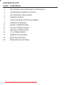
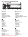
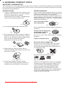
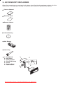
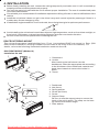
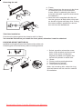
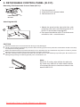
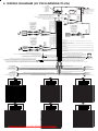
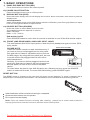
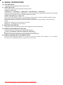
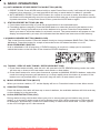
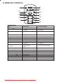
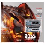
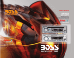
Downloaded from Caradio-Manual.com Manuals
CONTENTS LIST
PAGE CONTENTS
2
BUTTONS LOCATION AND FUNCTIONS
3
HANDLING COMPACT DISCS
4
ACCESSORY INCLUDED
5
INSTALLATION
7
DETACHABLE CONTROL PANEL
8
WIRING DIAGRAM
9
BASIC OPERATIONS
10
11
AUDIO OPERATIONS
RADIO OPERATIONS
12
CD OPERATIONS
13
REMOTE CONTROL
14
SPECIFICATIONS
15
TROUBLE SHOOTING
Downloaded from Caradio-Manual.com Manuals
1
1. BUTTONS LOCATION AND FUNCTIONS
1
2
10
17
12
5
16
4
14
6
8
11
13
3
15
9
7
18
1. Panel Release Button
2. Mute Button
3. CD Eject Button
4. Audio Button
5. Display Button
6. Local / Distant Button
7. Preset Memory Buttons
8. Mono / Stereo Button
9. Scan Button
10. Volume Knob
11. Automatically Store / Preset Scan Button
12. Power Button
13. Band/Loudness Button
14. Tuning Up/Down & Track Up / Down Buttons
15. Remote Control Receiver
16. Source Button
17. Preset Equalizer Button
18. Aux In Jack
1. Tecla para remover o painel frontal
2. Tecla Mute
3. Tecla para ejetar o disco
4. Tecla de ajuste de audio
5. Tecla Display
6. Tecla Local/Distante
7. Teclas de memória de estações
8. Tecla estéreo/mono
9. Tecla Scan
10. Controle de volume
11. Tecla automática (As) / Preset Scan (Ps)
12. Tecla Ligar/desligar
13. Tecla Banda / Loudness
14. Teclas de sintonização de estações / mudança de faixas de música
15. Sensor do controle remoto
16. Tecla Source
17. Tecla Equalizador pré-programado
18. Entrada Auxiliar
1. Entriegel-Taste Bedienteil
2. Stumm-Taste
3. CD-Auswurftaste
4. Audio-Taste
5. Display-Taste
6. Local / Distant-Taste
7. Senderspeichertasten
8. Mono / Stereo-Taste
9. Scan- Taste
10. Lautstärkenregler
11. AMS Taste
12. Einschalt-Taste
13. Frequenzband-Taste
14. Titel AUF / AB - Taste
15. Fernbedienungs-Taste
16. Source-Taste
17. PEQ-Taste
18. Front-Audio-Anschluss
1. Extracción del panel frontal
2. Silenciamiento rápido
3. Apertura del panel motorizado y expulsión del disco
4. Tecla Audio
5. Selección información Display
6. Botón Distancia/Local
7. Botones de estaciones memorizadas
8. Botón selección mono/estéreo
9. Botón De Búsqueda
10. Botón De Volumen
11. Automática de emisoras/ selección de memorias
12. Encendido/Apagado
13. Selector Bandas
14. Botón de selección de emisoras & banda de música
15. Receptor de control remoto
16. Selección modos Radio/CD/Entrada auxiliar
17. Tecla de ecualización
18. Entrada de auxiliar
1. Bouton De Déclenchement Du Panneau
2. Bouton D'assourdissement
3. Bouton Éjection D'un Cd
4. Bouton De Sélection Audio
5. Bouton D'écran / Affichage D'information
6. Bouton Local/distant
7. Boutons Des Stations Préréglées (m1 ~m6)
8. Bouton De La Stéréo Du Mono
9. Bouton Du Scanner
10. Bouton De Volume
11. Bouton De Stockage Des Stations Dans La Mémoire
12. Bouton D'alimentation
13. Bouton De Bande
14. Bouton De Recherche Des Stations/pistes : En Avant / En Arrière
15. Récepteur De La Commande À Distance
16. Bouton De Régime
17. Bouton De PEQ
18. Aux A Jack
1. Tasto Rilascio Frontalino
2. Tasto Mute
3. Tasto Eject
4. Audio Controlla
5. Tasto Display
6. Bottone Distante Locale
7. Tasti Stazioni Memorie Preimpostate
8. Bottone di Stereo/Mono
9. Tasto Scan
10. Tasto Volume
11. Tasto AS/PS
12. Tasto Power
13. Tasto Banda/Forte
14. Tasto sintonizzazione su/gui & traccia su/gui
15. Destinatario di controllo remoto
16. Tasto Mode
17. Bottone di equilizzatore preprogrammato
18. Entrada Aux
Downloaded from Caradio-Manual.com Manuals
2
2. HANDLING COMPACT DISCS
MOISTURE CONDENSATION
On a rainy day or in a very damp area, moisture may condense on the lenses inside the unit. Should this
occur, the unit will not operate properly. In such a case, remove the disc and wait for about an hour until
the moisture has evaporated.
NOTES ON CDs
NOTES ON DISCS
1. A dirty or defective disc may cause sound
dropouts while playing. To enjoy optimum
sound, handle the disc as follows.
Handle the disc by its edge. To keep the disc
clean, do not touch the surface (P.1).
If you use the discs explained below, the sticky
residue can cause the CD to stop spinning and
may cause malfunction or ruin your discs.
Do not use second-hand or rental CDs that have a
sticky residue on the surface (for example, from
peeled-off stickers or from ink, or glue leaking
from under the stickers).
There are paste residue.
Ink is sticky (P.5).
****
*******
P. 1
2. Do not stick paper or tape on the disc (P.2).
P. 5
*******
******* *******
Do not use CDs with old labels that are beginning
to peel off.
Stickers that are beginning
to peel away, leaving a
sticky residue (P.6).
P. 6
P. 2
3. Do not expose the discs to direct sunlight or
heat sources such as hot air-ducts, or leave
them in a car parked in direct sunlight where
there can be a considerable rise in
temperature inside the car (P.3).
**************
*******
*******
*******
Do not use your CDs with labels or stickers
attached.
Labels are attached (P.7).
*******
*******
*******
*******
*******
P. 7
Do Not Use Special Shape CDs
Be sure to use round shape CDs only for this
unit and do not use any special shape CDs.
Use of special shape CDs may cause the unit
to malfunction.(P.8).
P. 3
4. Before playing, clean the discs with an
optional cleaning cloth. Wipe each disc from
the center out (P.4).
P. 8
Be sure to use CDs with disc mark
RECORDABLE
P. 4
REWRITABLE
Only for this unit.
5. Do not use solvents such as benzine,
thinner,commercially available cleaners, or
antistatic spray intended for analog discs.
CD-Rs and CD-RWs which have not undergone
finalization processing cannot be played. (For
more information on finalization processing,
refer to the manual for your CD-R/CD-RW
writing software or CD-R/CD-RW recorder.)
Additionally, depending on the recording status,
it may prove impossible to play certain CDs
record on CD-R or CD-RW.
Downloaded from Caradio-Manual.com Manuals
3
3. ACCESSORY INCLUDED
When first unpacking your new head unit, please check first that the package contains all of the
items below. If something is missing, contact the store where you purchased the player.
Owner s Manual
Ow
ma ner
n u ’s
al
Warranty Card
Wa
rr
C a a n ty
rd
Remote control
Lithium Battery
0
CR2 25
+
3V
Half Sheeve
Insert Key
1.
2.
3.
4.
5.
6.
7.
Dashboard
Nut (5mm)
Spring washer
Screw (4X12mm)
Screw
Support Strap
Plain washer
1
6
7
4
2
3
5
Downloaded from Caradio-Manual.com Manuals
4
4. INSTALLATION
Before finally installing the unit, connect the wiring temporarily and make sure it is all connected up
properly and the unit and system work properly.
Use only the parts included with the unit to ensure proper installation. The use of unauthorized parts
can cause malfunctions.
Consult with your nearest dealer if installation requires the drilling of holes or other modifications of the
vehicle.
Install the unit where it does not get in the driver's way and cannot injure the passenger if there is a
sudden stop, like an emergency stop.
If installation angle exceeds 30° from horizontal, the unit might not give its optimum performance.
30°
Avoid installing the unit where it would be subject to high temperature, such as from direct sunlight, or
from hot air, from heater, or where it would be subject to dust dirt or excessive vibration.
Be sure to remove the front panel before installing the unit.
DIN FRONT/REAR-MOUNT
This unit can be property installed either from Front (conventional DIN Front-mount) or Rear (DIN
Rear-mount installation, utilizing threaded screw holes at the sides of the unit chassis). For
details, refer to the following illustrated installation methods A and B.
DIN FRONT-MOUNT (Method A)
Installation the unit
1
2
182
53
3
1
6
1.
2.
3.
4.
5.
6.
7
4
2
5
3
1. Dashboard
2. Holder
After inserting the half sleeve into the
dashboard, select the appropriate tab according
to the thickness of the dashboard material and
bend them inwards to secure the holder in
place.
3. Screw
Dashboard
Nut (5mm)
Spring washer
Screw (5x15mm)
Screw
Support Strap
Be sure to use the support strap to secure the
back of the unit in place. The strap can be bent
by hand to the desired angle.
7. Plain washer
Downloaded from Caradio-Manual.com Manuals
5
Removing the unit
a
a. Frame
b. Insert fingers into the groove in the front
of frame and pull out to remove the
frame. (When re-attaching the frame,
point the side with a groove down wards
and attach it.)
c. Insert the levers supplied with the unit
into the grooves at both sides of the unit
as shown in figure until they click. Pulling
the levers makes it possible to remove
the unit from the dashboard.
b
c
Trim Plate Installation:
Push the trim plate against the chassis until it is fitted.
You must do this before you install the front panel, otherwise it can't be attached.
DIN REAR-MOUNT (METHOD B)
Installation using the screw holes on the sides of the unit.
Fastening the unit to the factory radio mounting bracket.
1. Select a position where the screw
holes of the bracket and the screw
holes of the main unit become
aligned (are fitted) and tighten the
screws at 2 places on each side.
2. Screw
3. Factory radio mounting bracket.
4. Dashboard or Console
5. Hook (Remove this part)
2
4
5
3
Note: the mounting box, outer trim ring,
and half-sleeve are not used for method
B installation.
2
5
Downloaded from Caradio-Manual.com Manuals
6
5. DETACHABLE CONTROL PANEL (D.C.P.)
Removing The Detachable Control Panel (D.C.P.).
1. Turn the power off
2. Press the D.C.P. release button
3. Remove the D.C.P.
PANEL RELEASE
BUTTON
Attaching the DCP
2
A
B
1. Attach the panel at the right side first, with
point B on the main unit touching point A on
the D.C.P. (As shown on the digram).
2. Then press the left side of D.C.P. onto the main
unit until a click sound is heard.
CAUTION
DO NOT insert the D.C.P from the left side. Doing so may damage it.
The D.C.P can easily be damaged by shocks. After removing it, place it in a protective case and be careful not to drop
it or subject it to strong shocks.
When the release button is pressed and the D.C.P is unlocked, the car's vibrations may cause it to fall. To prevent
damage to the D.C.P, always store it in a protective case after detaching it.
The rear connector that connects the main unit and the D.C.P is an extremely important part. Be careful not to
damage it by pressing on it with fingernails, pens, screwdrivers, etc.
Socket
Note:
If the D.C.P is dirty, wipe off the dirt with soft,
dry cloth only. And use a cotton swab soaked
in isopropyl alcohol to clean the socket on the
back of the D.C.P.
Downloaded from Caradio-Manual.com Manuals
7
6. WIRING DIAGRAM (20 PIN HARNESS PLUG)
FUSE
SICHERUNG
FUSIBLE
FUSíVEL
FUSIBLE
FUSIBILE
ANTENNA CABLE INPUT
ANTENNENVERLÄNGERUNGSKABEL
CÂBLE D'EXTENSION D' ANTENNE
ENTRADA PARA CABO DE ANTENA
CABLE DE ANTENA
CAVO ANTENNA ESTENDIBILE
20-PIN AUDIO/POWER HARNESS (See Figure 1)
20-PIN AUDIO/STROM- KABELGESCHIRR
PLAQUE 20 FICHES AUDIO/ALIMENTATION
CONECTOR DE 20 PINOS PARA AUDIO E ALIMENTACAO
CONECTOR DE AUDIO / POTENCIA DE 20 PIN
CONNETTORE ISO ( vedi figura 1)
WHITE
WEISS
BLANC
BRANCO
BLANCO
BIANCO
HC-L
R-CH
AUX IN
RED/ROT/ROUGE/VERMELHO/ROJO/ROSSO
RCA-TO-RCA CABLES
(not supplied)
RCA-TO-RCA-KABEL
(nicht geliefert)
CABLES RCA-TO-RCA
(non fournis.)
CABOS RCA A RCA
(não fornecidos)
CABLES RCA A RCA
(no incluidos)
CAVO RCA A RCA
( non fornito)
HC-R
AMP
YELLOW
YELLOW
YELLOW
AMARELO
AMARILLO
GIALLO
L-CH
REAR LINE OUT---GREY
RÜCKANSCHLUSS-AUS GRAU
SORTIE ARRIERE-GRIS
SAIDA TRASEIRA - CINZA
SALIDA DE LINEA TRASERA -GRIS
LINE OUT POSTERIORE---GRIGIO
RCA-TO-RCA CABLES
(not supplied)
RCA-TO-RCA-KABEL
(nicht geliefert)
CABLES RCA-TO-RCA
(non fournis.)
CABOS RCA A RCA
(não fornecidos)
CABLES RCA A RCA
(no incluidos)
CAVO RCA A RCA
( non fornito)
WHITE
WEISS
BLANC
BRANCO
BLANCO
BIANCO
BLUE
BLAU
BLEU
AZUL
AZUL
BIANCO
SUB-WOOFER
WHITE
WEISS
BLANC
BRANCO
BLANCO
BIANCO
RED/ROT/ROUGE/VERMELHO/ROJO/ROSSO
WHITE
WEISS
BLANC
BRANCO
BLANCO
BIANCO
HC-L
Memory/Battery
Connect to a constant 12 volt source. The radio will not work if this wire is not connected.
Geds/Batterie
Verbinden Sie sich mit einer Konstanten 12 Voltquelle. Das Radio wird nicht funktionieren, wenn
diese Leitung nicht verbunden ist.
Mémoire/Pile
Connectez-vous à une source constante du volt 12. La radio ne fonctionnera pas si ce fil n'est pas
connecté.
Memória/Bateria
Conecte a uma fonte constante de 12V. O radio nao funcionara se este fio nao estiver conectado.
Memoria/Batería
Conecte a un origen constante de 12 volt. La radio no funcionará si este alambre no está conectado.
HC-R
AMP
FRONT LINE OUT---GREY
VORDERER AUSGANG--SCHWARZ
SORTIE ARRIERE-GRIS
SAIDA TRASEIRA - CINZA
SALIDA DE LINEA TRASERA -GRIS
LINE OUT POSTERIORE---GRIGIO
RCA-TO-RCA CABLES
(not supplied)
RCA-TO-RCA-KABEL
(nicht geliefert)
CABLES RCA-TO-RCA
(non fournis.)
CABOS RCA A RCA
(não fornecidos)
CABLES RCA A RCA
(no incluidos)
CAVO RCA A RCA
( non fornito)
Memoria/ Batteria
Collegatevi a una 12 sorgente di volt costante. La radio non lavorerà se questo filo non è collegato
RED/ROT/ROUGE/VERMELHO/ROJO/ROSSO
YELLOW/YELLOW/YELLOW/AMARELO/AMARILLO/GIALLO
Power antenna wire and remote turn on lead.
Treiben Sie Antennenleitung und entfernte Drehungsführung an.
Le fil de l'antenne de la puissance et l'éloignement mettent la conduite sous tension.
Fio Para Antena Eletrica.
Impulse alambre de antena y turno remoto en liderazgo.
Il filo di potenza di antenna e il remoto accendono comando.
Ground Connect to ground terminal or Clean unpainted metal part of chassis
Ground verbindet sich mit Bodenendstation oder reinigt nichtgestrichenen Metallteil von Chassis
Le Ground se Connecte au terminal de la terre ou Lave la partie non peinte du métal du chssis
Terra- Conecte Ao Terminal Negativo Ou A Uma Superficie Metalica (sem Pintura) Do Chassi.
El Ground Conecta a terminal de tierra o Completamente despintó parte metálica de chasis
Il Ground si collega a terminale terrestre di parte di metallo non verniciare pulita di telaio
LEFT FRONT
LINKE VORDERSEITE
FACE AVANT GAUCHE
FRENTE ESQUERDO
PARTE frontal IZQUIERDA
PARTE anteriore SINISTRA
BLUE/BLUE/BLUE/AZUL/AZUL/BLU
RED/RED/RED/VERMELHO/ROJO/ROSSO
BLACK/BLACK/BLACK/PRETO/NEGRO/NERO
WHITE/WEISS/BLAC/BRANCO/BLANCO/BLANCO
3
4
5
6
7
12
13
14
15
16
17
9
10
1
18
19
20
11
WIRE COLOR
GREY/BLACK
FUNCTION/LABEL
RIGHT FRONT SPEAKER (-)
2
GREY
RIGHT FRONT SPEAKER (+)
3
VIOLET
RIGHT REAR SPEAKER (+)
19
BLACK
FRONT PRE-AMP LINE OUT COMMON
20
WHITE
LEFT REAR PRE-AMP LINE OUT
20
4
VIOLET/BLACK
RIGHT REAR SPEAKER (-)
5
6
GREEN
LEFT REAR SPEAKER (+)
7
GREEN/BLACK
LEFT REAR SPEAKER (-)
8
RED
IGNITION(ACC)
9
BLACK
REAR PRE-AMP LINE OUT COMMON
10
11
RED
WHITE
12
WHITE/BLACK
RIGHT REAR PRE-AMP LINE OUT
LEFT FRONT SPEAKER (+)
LEFT FRONT SPEAKER (-)
BLUE
POWER ANTENNA
15
YELLOW
BATTERY(+)
16
BLACK
WHITE
RED
CHASSIS GROUND
13
18
LEFT FRONT PRE-AMP LINE OUT
RIGHT FRONT PRE-AMP LINE OUT
11
2
3
4
5
6
7
12
13
14
15
16
17
Figure 1
5
12
13
14
15
6
7
8
9
10
1
16
17
18
19
20
11
FONCTION / MARQUE
BLANC
ROUGE
CHASSIS TERRE
SORTIE AVANT GAUCHE PRE-AMPLI
SORTIE AVANT DROITE PRE-AMPLI
NOIR
SORTIE AVANT COMMUNE PRE-AMPLI
PIN
1
2
3
4
5
6
7
8
9
10
11
12
13
14
15
16
17
18
19
BLANC
SORTIE PRE-AMP ARRIERE GAUCHE
20
ENCEINTE AVANT DROIT (-)
VIOLET
ENCEINTE AVANT DROIT (+)
ENCEINTE ARRIERE DROIT (+)
VIOLET / NOIR
ENCEINTE ARRIERE DROIT (-)
VERT
ENCEINTE ARRIERE GAUCHE (+)
VERT/NOIR
ENCEINTE ARRIERE GAUCHE (-)
ROUGE
ALLUMAGE (ACC)
NOIR
SORTIE COMMUNE ARRIERE PRE-AMP
ROUGE
BLANC
SORTIE PRE-AMP ARRIERE DROITE
ENCEINTE AVANT GAUCHE (+)
ENCEINTE AVANT GAUCHE (-)
GRIS
NOIR/BLANC
BLEU
PUISSANCE ANTENNE
BATTERIE (+)
JAUNE
NOIR
IGNICIÓN (ACC)
NEGRO
LINEA DE SALIDA PRE-AMP TRASERA
ROJO
LINEA DE SALIDA PRE-AMP TRASERA DERECHA
BLANCO
ALTAVOZ FRONTAL IZQUIERDO (+)
BLANCO / NEGRO ALTAVOZ FRONTAL IZQUIERDO (-)
AZUL
ALIMENTACIÓN DE ANTENA
AMARILLO
BATERÍA(+)
NEGRO
CHASIS DE TIERRA
BLANCO
SALIDA L. PREAMP FRONTAL IZQUIERD
SALIDA L. PREAMP FRONTAL DERECHA
ROJO
NEGRO
SALIDA L. PREAMP FRONTAL COMUN
LINEA DE SALIDA PRE-AMP TRASERA IZQUIERDA
IDENTIFICAZIONE PIN
1
18
19
20
11
12
13
14
15
16
17
18
19
20
11
Pin View
ZÜNDUNG (ACC)
RÜCK-PRE-AMP-ANSCHLUSS -AUS
ROT
WEISS
RECHTER RÜCK-PRE-AMP-ANSCHLUSS-AUS
LINKER VORDERLAUTSPRECHER (+)
LINKER VORDERLAUTSPRECHER (-)
ALTO-FALANTE DIANTEIRO DIREITO (-)
ALTO-FALANTE DIANTEIRO DIREITO (+)
(-)
IGNIÇÃO (ACC)
SAÍDA PRE-AMP TRASEIRA (FIO COMUM)
SAÍDA PRE-AMP TRASEIRA DIREITA
ALTO-FALANTE DIANTEIRO ESQUERDO (+)
ALTO-FALANTE DIANTEIRO ESQUERDO (-)
13
MOTORISIERTE ANTENNE
BATTERIE (+)
GEHÄUSEERDUNG
HINTERER VORVERSTÄRKERAUSGANG
ROT
SCHWARZ
RECHTERVORDERERVORVERSTÄRKERAUSGANG
WEISS
LINKER RÜCK-PRE-AMP-ANSCHLUSS
ANTENA ELÉTRICA
BRANCO
VERMELHO
PRETO
MASSA (FIO TERRA)
SAIDA LINHA PRENTE ESQ
SAIDA LINHA PRENTE DIR.
COMUM SAIDA LINHA PRENTE
SAÍDA PRE-AMP TRASEIRA ESQUERDA
Downloaded from Caradio-Manual.com Manuals
VORDERERVORVERSTÄRKERAUSGANG NORMAL
2
3
4
5
12
13
14
15
FIGURA 1
FUNKTION / ETIKETT
SCHWARZ
WEISS
ALTAVOZ TRASERO IZQUIERDO (-)
ROJO
10
ROT
GELB
SCHWARZ
VERDE / NEGRO
9
LINKER RÜCKLAUTSPRECHER (-)
BLAU
ALTAVOZ TRASERO IZQUIERDO (+)
VERDE
8
LINKER RÜCKLAUTSPRECHER (+)
FUNCI
VIOLETA / NEGRO
7
GRÜN/SCHWARZ
8
10
20
ALTAVOZ TRASERO DERECHO (+)
6
GRÜN
9
19
ALTAVOZ TRASERO DERECHO (-)
5
VIOLETT/SCHWARZ RECHTER RÜCKLAUTSPRECHER (-)
8
18
ALTAVOZ FRONTAL DERECHO (+)
4
RECHTER VORDERLAUTSPRECHER (+)
RECHTER RÜCKLAUTSPRECHER (+)
WEISS/SCHWARZ
BLANCO
7
17
Vista de los Pin
ALTAVOZ FRONTAL DERECHO (-)
3
RECHTER VORDERLAUTSPRECHER (-)
6
16
VIOLETA
2
KABELFARBE
5
15
GRIS
1
GRAU
4
14
GRIS/ NEGRO
10
GRAU/SCHWARZ
3
13
COLOR DE CABLE
9
1
2
3
4
5
6
7
8
9
10
11
12
13
14
15
16
17
18
19
20
2
12
Imagen 1
Vue des fiches
8
PIN
VIOLETT
4
Conector de 20 pinos para audio e alimentação
20-PIN AUDIO/STROM-KABELGESCHIRR
1
3
FICHE COULEUR DU CABLE
1
GRIS/NOIR
2
3
4
5
6
7
8
9
10
11
12
13
14
15
16
17
18
19
17
2
Schéma 1
1
CONECTOR DE AUDIO / POTENCIA 20 PIN
PLAQUE 20 FICHES AUDIO/ALIMENTATION
8
PIN
RIGHT REAR
RICHTIGE RÜCKSEITE
ARRIERE DROIT
DIREITO JUSTO
PARTE POSTERIOR ADECUADA
RETRO GIUSTO
VIOLET/VIOLETT/VIOLET/VIOLETA/VIOLETA/VIOLA
Pin View
Figure 1
14
VIOLET-BLACK/VIOLETT-SCHWARZ/VIOLET-NOIR/VIOLETA-PRETO
/VIOLETA-NEGRO/VIOLA-NERO
GREEN/GRÜN/VERT/VERDE/VERDE/VERDE
2
RIGHT FRONT
RICHTIGE VORDERSEITE
FACE AVANT DROITE
FRENTE JUSTO
PARTE FRONTAL ADECUADA
PARTE ANTERIORE GIUSTA
GREY/GRAU/GRIS/CINZA/GRIS/GRIGIO
GREEN-BLACK/GRÜN-SCHWARZ/VERT-NOIR/VERDE-PRETO/VERDE-NEGRO/VERDE-NERO
20-PIN AUDIO/POWER HARNESS
11
GREY-BLACK/GRAU-SCHWARZ/GRIS-NOIR/CINZA-PRETO
/GRIS-NEGRO/GRIGIO-NERO
WHITE-BLACK/WEISS-SCHWARZ/NOIR-BLANC/BRANCO-CINZA/BLANCO -NEGRO/BIANCO-NERO
LEFT REAR
LINKE RÜCKSEITE
ARRIERE GAUCHE
TRASEIRO ESQUERDO
PARTE POSTERIOR IZQUIERDA
RETRO SINISTRO
1
Accessory/Ignition - Connect to a switched 12 volt source.
Zubehr/ Zündung - verbindet sich mit einer umgeschalteten 12 Voltquelle.
Accessoire/ Allumage - se Connecte à une source commutée du volt 12.
Acessorio / Ignicao - Conecte a uma fonte de 12V chaveada.
Accesorio/ Ignición - Conecta a un origen conmutado de 12 volt.
L'accessorio/ L'accensione - si Collega a una 12 sorgente di volt commutata.
COLORE CAVO
6
7
8
9
10
16
17
18
19
20
VISUALE PIN
FUNZIONE
PIN
1
2
3
4
5
6
7
8
9
10
11
12
13
14
15
16
17
18
19
BIANCO
ROSSO
BLACK
MESSA A TERRA
USCITA FRONTALE SINISTRO PRE-AMP
USCITA FRONTALE DESTRO PRE-AMP
USCITA FRONTALE COMUNE PRE-AMP
20
BIANCO
AMPLIFICATORE CASSA POST. SX
GRIGIO/NERO
VIOLA
CASSA ANTERIORE DESTRA (-)
CASSA ANTERIORE DESTRA(+)
CASSA POSTER. DESTRA (+)
VIOLA/NERO
CASSA POSTER. DESTRA (-)
VERDE
CASSA POSTER. SINISTRA (+)
VERDE/NERO
CASSA POSTER. SINISTRA (-)
GRIGIO
ROSSO
ACCENSIONE (TAKE OUT NIEZIONE)
NERO
MESSA A TERRA
ROSSO
BIANCO
AMPLIFICATORE CASSA POST. DESTRA
CASSA ANTERIORE SINISTRA (+)
CASSA ANTERIORE SINISTRA (-)
BIANCO/NERO
BLU
GIALLO
NERO
ANTENNA
BATTERIA(+)
7. BASIC OPERATIONS
1) PANEL RELEASE BUTTON (REL)
Press this button to remove the control panel.
12) POWER ON/OFF BUTTON
Press this button to turn on or off the power.
5) DISPLAY BUTTON (DISP)
Press this button briefly, the LCD will display the clock for about 2 seconds, then return to previous
display mode.
Clock Adjustment
Under clock display mode, press DISP button until the LCD flashes, press Tuning Up Button to adjust
hour and Tuning Down Button to adjust minute.
16) SOURCE BUTTON (SOURCE)
Press this button to select Radio and CD modes.
The available selections depends on version:
Radio CD Player
Radio > CD > AUX in
Sub-woofer On/Off
Press SOURCE button for more than 3 seconds to activate or turn off the Sub-woofer output.
18) FRONT (AND REAR PANEL) AUXILIARY INPUT JACKS
This unit features AUX IN line input jacks on both the front (headphone type) and rear (RCA
type) panels.
AUX IN JACK IN PANEL
PLEASE NOTE:
These two inputs cannot be used simultaneously. If
you have a source unit plugged into the rear panel
jack and wish to listen to a portable device (such as
an MP3 player) by using the front panel jack, be sure
to power off the unit plugged into the rear unit to
Left Audio
avoid interference.
Right Audio
Ground
Similarly, if you have a device plugged into the front
panel jack and wish to listen to the unit plugged into
3.5mm Audio In Cable (not included)
the rear panel, be sure to turn off the front panel
device.
To select either the front or rear AUX IN device as a listening source, press the SOURCE
button to select AUX mode. To cancel AUX IN listening, press SOURCE again.
1
2
3
RESET BUTTON
The RESET button is located on the main unit (as shown on the diagram). To press it vertically with a
ballpoint pen or metal object will activate it. The reset button is to be activated for the following reasons:
Initial installation of the unit when all wiring is completed.
All the function buttons do not operate.
Error symbol on the display.
Note: If the unit cannot function normally after reseting, please use a cotton swab soaked in
isopropyl alcohol to clean the socket on the back of the control panel.
Downloaded from Caradio-Manual.com Manuals
9
8. AUDIO OPERATIONS
10) VOLUME KNOB
Turn this knob to adjust desired volume level.
4) AUDIO BUTTON
Press this button to select desired audio function.
ORDER OF FUNCTION:
VOLUME(VOL) -> BASS(BAS) -> TREBLE(TRE) ->BALANCE(BAL) ->FADER(FAD)
While the selected function is displayed, turn Volume Knob to adjust the level within 5 seconds,
otherwise the unit will return to volume adjustment mode.
BEEPS 2ND,BEEP ALL ,BEEP OFF
Press and hold SELECT button to determine how the beep sound is generated when the keys
are pressed,using V-UP/V-DN to select the desires settings:
BEEP 2ND Beeps only when the second function of the dual function button is selected (long
press).
BEEP ALL Beeps when any buttons is pressed.
BEEP OFF To disable the beep option.
2) MUTE BUTTON (MUTE)
Press this button to mute the sound. Press it again to resume listening.
17) PRESET EQUALIZER BUTTON (EQ)
Press this button to toggle the following EQ settings:
FLAT->CLASSICS->POP M->ROCK M->DSP OFF
At DSP OFF mode, EQ will be controlled by Bass/Treble setting.
13) BAND/LOUDNESS BUTTON (BAND/LOUD)
Press the Band/Loudness Button for couple of seconds to switch the loudness on or off. When
Loudness is on, display will show 'Loud On' for a few seconds.
Downloaded from Caradio-Manual.com Manuals
10
9. RADIO OPERATIONS
11) AUTO MEMORY STORE/PRESET SCAN BUTTON (AS/PS)
1. PRESET SCAN: Press AS/PS button briefly to enter Preset Scan mode, it will scan all the preset
stations in the memories, you can hear that it will stay on each station for about 5 seconds.
2. AUTO MEMORY STORE: Press AS/PS button for couple of seconds to enter Auto Store mode,
this feature will automatically scan the current band and enter up to 6 strongest stations into the
6 preset memories. To stop Auto Store & Scan, press the AS/PS button again.
7) STATION PRESET BUTTONS (M1-M6)
1. Press these buttons briefly to recall the stored stations in the selected band.
2. Presetting stations manually, Press the BAND button to select the band for the stations to be
preset. Use Tuning Up/Down to tune in the stations to be preset. Press the Preset button at
which you want to store the station for at least 2 second. The preset number will appear on the
display accompanied by a beep, this indicates that the station has been stored into memory.
13) BAND/LOUDNESS BUTTON (BAND/LOUD)
This a dual function button. Press this button shortly to change between BAND FM1, FM2, FM3 or
AM bands. Press this button for couple of seconds to turn Loudness function on or off.
DUAL FREQUENCY SWITCH
Unit is defaulted in U.S.A frequency, if EURO frequency is required, a sharp pen is needed to
switch the button on the left side of the chassis to EURO frequency.
US
EU
14) TUNING / SEEK UP AND TUNING / SEEK DOWN BUTTONS
1. Press these buttons briefly, and the unit will operate in AUTO SEARCH tuning mode, the radio
will tune up or down to the next station and remain on that station.
2. Press these buttons for more than 2 seconds, operate as MANUAL SEARCH buttons, under this
mode the tuning frequency will advance up or down rapidly when the button is pressed. If the
buttons are not pressed within 3 seconds, they will return to auto search mode.
8) MONO STEREO BUTTON (MO/ST)
When you receive a station, ST on the display will be on. Press this button to enter Mono mode.
9) SCAN BUTTON(SCAN)
Press this button, the radio will tune up to search stations, the available stations will blink and stay
on the display for a few seconds.
6) LOCAL/DISTANT BUTTON (LOC)
During station tuning, this button allows you prior to access strong local station only (Local
mode), or to access a wider range of using distant mode (DX). When powered on, DX mode will
be defaulted automatically; Press LOC button briefly to select Local mode and L OCAL symbol
on the LCD will light up for a few seconds.
Downloaded from Caradio-Manual.com Manuals
11
10.CD OPERATIONS
M1) PAUSE BUTTON (PAUSE)
Press this button to pause CD play, press again to release pause.
M2) SCAN BUTTON (SCAN)
Press this button, the first 10 seconds of each track will be played sequentially until this button
is pressed again, then normal play will resume at the current track.
M3) REPEAT BUTTON (REPEAT)
Press this button, the current track will be played repeatedly until this button is pressed again.
M4) SHUFFLE BUTTON (SHUFFLE)
Press this button to play all tracks on CD in random. Press again to deactivate it.
14) TRACK UP AND TRACK DOWN BUTTON
Press the Track Up Button to skip to the next track or previous track. Press the Track Down
button during play will return to the beginning of the current track, press it one more time to skip
to previous skip. Press and hold Track Up/Down Button to fast forward or fast reverse. CD
player starts playing when you release the button.
EJECT BUTTON
Press this button to eject the CD from the unit. The receiver will switch to radio mode
automatically.
EJECT BUTTON
Downloaded from Caradio-Manual.com Manuals
12
11.REMOTE CONTROL
8
1
9
2
3
10
4
5
11
6
12
7
13
14
OPERATIONS:
Key
Radio Mode
CD Player Mode
1. Power ( )
Power On/Off
Power On/Off
2. Volume Up/Down
Adjust Vol,Bas,
Tre,Fad,Bal
Adjust Vol,Bas,
Tre,Fad,Bal
3. DISP
Display Clock
Display Clock
4.Stereo/Mono
Stereo/FM Mono
No Function
5. Tuning Up/Down
Tuning/Seek Up/Down
Track Up/Down
6. LOC
Local/Distant
No Function
7. Scan
Station Scan
No Function
8. Mute
Mute
Mute
9. Audio
Select Vol, Bas,
Tre, Fad, Bal
Select Vol, Bas,
Tre, Fad, Bal
10. Sub-woofer(SUB)/
Source
Sub-woofer/
Change to CD or
AUX IN
Sub-woofer/
Change to Radio or AUX IN
11. Band/Loud
Band/Loudness
Loudness
12. AS/PS
13. EQ
14. Numeric Key(1)
(2)
(3)
(4)
(5)
(6)
Auto Store/Preset Scan
No function
Preset EQ
Preset EQ
Preset station 1
Pause
Preset station 2
CD scan
Preset station 3
Repeat
Preset station 4
Shuffle
Preset station 5
No Function
Preset station 6
No Function
Downloaded from Caradio-Manual.com Manuals
13
12. SPECIFICATIONS
CD PLAYER
System
Usable disc
Sampling frequency
No of quantization bits
Frequency
Number of channels
S/N Ratio
RADIO SECTION
FM
Frequency Range
Intermediate Frequency
Usable Sensitivity
Stereo Separation
S/N Ratio
AM/MW
Frequency Range
CD Player
Sistema:
Tipo de disco:
Frequência de Amostragem:
Conversor D/A:
Resposta de frequencia
Número de canais:
Relação sinal/ruído:
Rádio FM
Faixa de Frequencia:
Compact disc audio system
Compact disc
44.1KHz
1bit
5-20,000Hz
2 stereo
70dB
87.5-107.9MHz U.S.
87.5-108MHz EURO
10.7 MHz
Better than 15dB at S/N 30 dB
25 dB at 1KHz
50 dB
Frequência Intermediária:
Sensibilidade útil:
Separação estéreo
Relação Sinal/Ruído
Sistema áudio CD
CD
44.1KHz
1bit
5-20,000Hz
2 estéreo
70dB
87.5-107.9MHz U.S.
87.5-108MHz EURO
10.7 MHZ
melhor que 15dB a S/N 30dB
25 dB at 1KHz
50 dB
AM/MW
Faixa de frequencia:
REMARK :
Specifications subject to change without notice.
530-1710KHz U.S.
522-1620KHz EURO
450KHz
Frequencia intermediária:
Melhor do que 45dB
Sensibilidade útil:
40dB
Relação Sinal/Ruído:
Geral:
Alimentação:
DC 11-14V
Polaridade:
Terra negativo
Impedancia alto-falantes:
4ohms
Potência de saída:
50w x 4
Nota:
As especificações estão sujeitas a alterações sem prévio aviso.
CD PLAYER
System
Abspielbare Discs
Sampling-Frequenz
Anzahl Quantisierungsbits
Frequenz
Anzahl Kanäle
Signalrauschabstand
RADIOTEIL
FM
Frequenzbereich
CD PLAYER
Sistema:
Disco:
Frecuencia Muestreo:
Cuantificación:
Frecuencia:
Número de canales:
Relación señal/Ruido S/N Ratio
RADIO SECCIÓN
FM
Rango Frecuencia:
Intermediate Frequency
Usable Sensitivity
S/N Ratio
GENERAL
Power Supply
Polarity
Speaker impedance
Power Output
Zwischenfrequenz
Nutzbare Empfindlichkeit
Stereotrennung
Signalrauschabstand
AM/MW
Frequenzbereich
Zwischenfrequenz
Nutzbare Empfindlichkeit
Signalrauschabstand
ALLGEMEINES
Stromversorgung
Polarität
Lautsprecherimpedanz
Ausgangsleistung
530-1710KHz U.S.
522-1620KHz EURO
450KHz
Better than 45dB
40 dB
DC 11 -14V
Negative Ground
4 ohms
4x 50 Watts
Compact Disc Audio System
Compact Disc
44,1 kHz
1 bit
5-20.000Hz
2 Stereo
70 dB
87.5-107.9MHz U.S.
87.5-108MHz EURO
10.7 MHz
Besser als 15 dB bei einem
Signalrauschabstand von 30 dB
25 dB bei 1 kHz
50 dB
530-1710KHz U.S.
522-1620KHz EURO
450KHz
Besser als 45 dB
40 dB
DC 11 -14 V
Erde negativ
4 Ohm
50 W x 4
Frecuencia Intermedia:
Sensibilidad Útil:
Separación estereo:
S/N Ratio:
AM/MW
Rango Frecuencia:
Frecuencia Intermedia:
Sensibilidad útil:
S/N Ratio:
GENERAL
Alimentación:
Polaridad:
Impedancia altavoces:
Potencia de salida:
Compact disc audio system.
Compact Disc.
44.1KHz.
1bit.
5-20,000Hz.
2 estereo.
70dB
87.5-107.9MHz U.S.
87.5-108MHz EURO
10.7Mhz.
Mejor que 15dB a S/N 30dB.
25dB a 1Khz.
50dB.
530-1710KHz U.S.
522-1620KHz EURO
450KHz.
Mejor que 45dB.
40dB.
DC 11-14V.
Negativo a masa.
4 Ohms.
4x50W.
ANMERKUNG:
Technische Änderungen ohne Meldepflicht vorbehalten.
Nota:
Debido al rápido avance tecnológico, estas especificaciones están
sujetas a cambios sin previo aviso.
LECTEUR CD
Système
Disques utilisables
Fréquence échantillonnage
Nbre de quantisation bits
Fréquence
Nombre de canaux
Ratio S/B
SECTION RADIO
FM
Gamme de fréquences
LETTORE CD
Sistema
Tipo di disco
Frequenza di campionatura
N° quantizzazioni Bit
Frequenza
Numero di Canali
Rapporto S/N
SEZIONE RADIO
FM
Raggio di Frequenza
Fréquence intermédiaire
Sensibilité utilisable
Séparation stéréo
Ratio S/B
AM/MW
Plage de fréquences
Compact disc audio system
Compact disc
44.1KHz
1bit
5-20,000Hz
2 stéréo
70dB
87.5-107.9MHz U.S.
87.5-108MHz EURO
10.7 MHz
Plus de 15dB à S/B 30 dB
25 dB à 1KHz
50 dB
530-1710KHz U.S.
522-1620KHz EURO
450KHz
Fréquence intermédiaire
Supérieure à 45 dB
Sensibilité utilisable
40 dB
Rapport Signal/Bruit
GENERAL
Alimentation
11 -14V DC
Polarité
Masse / négative
Résistance des enceintes
4 ohms
Puissance de sortie
50W x 4
REMARQUE :
Les spécifications sont susceptibles d'être modifiées sans
préavis.
Frequenza intermedia
Sensibilità
Separazione Stereo
Rapporto S/N
AM/MW
Raggio di Frequenza
Frequenza intermedia
Sensibilità
Rapporto S/N
GENERALE
Alimentazione
Polarità
Impedenza altoparlanti
Potenza d'uscita
Sistema di Audio CD
CD
44.1KHz
1 bit
5-20,000 Hz
2 stereo
70db
87.5-107.9MHz U.S.
87.5-108MHz EURO
10.7 Mhz
migliore di 15dB a S/N 30 dB
25dB a 1KHz
50dB
530-1710KHz U.S.
522-1620KHz EURO
450Khz
migliore di 45dB
40dB
Dc11 14V
Terra negativo
4 ohms
4x 50 Watts
Le specifiche sono soggette a cambiamenti senza
Downloaded from Caradio-Manual.com Manuals
alcun preavviso.
14
13.TROUBLE SHOOTING
Before going through the check list, check wiring connection. If any of the problems persist after check
list has been made, consult your nearest service dealer.
Symptom
No power
Disc cannot be loaded
or ejected
Cause
Solution
The car ignition is not on.
If the power supply is properly connected
to the car accessory terminal, switch the
ignition key to ACC
The fuse is blown.
Replace the fuse.
Presence of CD disc inside
the player.
Remove the disc in the player, then put a
new one.
Inserting the disc in reverse
direction.
Insert the compact disc with the label
facing upward.
Compact disc is extremely
dirty or defective disc.
Clean the disc or try to play a new one.
Temperature inside the car is
too high.
Cool off or until the ambient temperature
returns to normal.
Condensation.
Leave the player off for an hour or so,
then try again.
Volume is in minimum.
Adjust volume to a desired level.
Wiring is not properly
connected.
Check wiring connection.
The operation keys do
not work
The built-in microcomputer is
not operating properly due to
noise.
Press the RESET button.
Front panel is not properly fixed into its
place
Sound skips.
The installation angle is
more than 30 degrees.
Adjust the installation angle to less than
30 degrees.
No sound
The disc is extremely dirty or a Clean the compact disc or try to play a
defective disc.
new one.
The radio does not
work.
The radio station
automatic selection
does not work.
The antenna cable is not
connected.
Insert the antenna cable firmly.
The signals are too weak.
Select a station manually.
ERROR 1
Mechanism Error
Press the reset button if the error code
does not disappear, consult your nearest
service dealer.
ERROR 2
Servo Error
Press the reset button if the error code
does not disappear, consult your nearest
service dealer.
If at any time in the future you should need to dispose of this product please note
that Waste electrical products should not be disposed of with household waste.
Please recycle where facilities exist. Check with your Local Authority or retailer for
recycling advice.(Waste Electrical and Electronic Equipment Directive)
Downloaded from Caradio-Manual.com Manuals
15
4 10 R - 02 1397
Downloaded from Caradio-Manual.com Manuals