1
Operation/Reference Guide
RADIA Eclipse
Dimmer Modules
RE-DM4 (120V, 240V)
RE-DM6 (120V, 240V)
R AD I A L i g h t i n g S ol u t i ons
Last Updated: 6/15/2007
AMX Limited Warranty and Disclaimer
All products returned to AMX require a Return Material Authorization (RMA) number. The RMA number is
obtained from the AMX RMA Department. The RMA number must be clearly marked on the outside of each
box. The RMA is valid for a 30-day period. After the 30-day period the RMA will be cancelled. Any shipments
received not consistent with the RMA, or after the RMA is cancelled, will be refused. AMX is not responsible
for products returned without a valid RMA number.
Warranty Repair Policy
•
AMX will repair any defect due to material or workmanship issues during the applicable warranty period at no cost to the AMX
Authorized Partner., provided that the AMX Authorized Partner is responsible for in-bound freight and AMX is responsible for
out-bound ground freight expenses.
•
The AMX Authorized Partner must contact AMX Technical Support to validate the failure before pursuing this service.
•
AMX will complete the repair and ship the product within five (5) business days after receipt of the product by AMX. The AMX
Authorized Partner will be notified if repair cannot be completed within five (5) business days.
•
Products repaired will carry a ninety (90) day warranty or the balance of the remaining warranty, whichever is greater.
•
Products that are returned and exhibit signs of damage or unauthorized use will be processed under the Non-Warranty Repair
Policy.
•
AMX will continue to provide Warranty Repair Services for products discontinued or replaced by a Product Discontinuance
Notice.
Non-Warranty Repair Policy
•
Products that do not qualify to be repaired under the Warranty Repair Policy due to age of the product or Condition of the product may be repaired utilizing this service.
•
The AMX Authorized Partner must contact AMX Technical Support to validate the failure before pursuing this service.
•
Non-warranty repair is a billable service.
•
Products repaired under this policy will carry a ninety (90) day warranty on material and labor.
•
AMX will notify the AMX Authorized Partner with the cost of repair, if cost is greater than the Standard Repair Fee, within five (5)
days of receipt.
•
The AMX Authorized Partner must provide a Purchase Order or credit card number within five (5) days of notification, or the
product will be returned to the AMX Authorized Partner.
•
The AMX Authorized Partner will be responsible for in-bound and out-bound freight expenses.
•
Products will be repaired within ten (10) business days after AMX Authorized Partner approval is obtained.
•
Non-repairable products will be returned to the AMX Authorized Partner with an explanation.
•
See AMX Non-Warranty Repair Price List for minimum and Standard Repair Fees and policies.
Table of Contents
Table of Contents
Radia Eclipse RE-DM4 Dimmer Module ..............................................................1
Overview .................................................................................................................. 1
Specifications............................................................................................................ 2
Suggested Loads ...................................................................................................... 3
Caution: Pre-Installation Notes ................................................................................. 3
RE-DM4 4-pin module connector (male) ................................................................... 3
Line-In Connections................................................................................................... 4
Lighting Application Drawings.................................................................................. 4
Radia Eclipse RE-DM6 Dimmer Module ..............................................................6
Overview .................................................................................................................. 6
Specifications............................................................................................................ 7
Suggested Installation Loads .................................................................................... 8
Caution: Pre-Installation Notes ................................................................................. 8
Line-In Connections................................................................................................... 8
Lighting Application Drawings.................................................................................. 9
AMX Lighting Systems .....................................................................................11
Overview ................................................................................................................ 11
Features.................................................................................................................. 11
Applications ............................................................................................................ 11
AMX Lighting Control Equipment........................................................................... 12
Installation ........................................................................................................15
Space Requirements ............................................................................................... 15
Wiring Considerations ............................................................................................ 15
Preparing/connecting captive wires .............................................................................. 15
AXLink wiring between multiple devices ...................................................................... 15
Power considerations.............................................................................................. 15
AXLink connections ....................................................................................................... 15
Conduit ................................................................................................................... 16
Enclosure Dimensions ............................................................................................. 17
RDA-ENC2, -ENC4, and -ENC6 enclosure and dimensions............................................ 17
RDA-ENC6B and RDA-ENC12B enclosures and dimensions .......................................... 17
Mounting AMX Lighting Enclosures........................................................................ 18
High-Voltage Connections ...................................................................................... 18
Connecting high-voltage, single-phase input power and loads..................................... 19
RDA-ENC6B 120 VAC single phase line input ............................................................... 20
RDA-ENC6B 120/240 VAC line input (single phase)...................................................... 20
RE-DM4 and RE-DM6 RADIA Eclipse Dimmer Modules
i
Table of Contents
Connecting high-voltage input power and loads........................................................... 21
RDA-ENC6B 120/208 VAC line input (three phase)....................................................... 21
RDA-ENC6B three phase line input connector reference .............................................. 22
RDC-PFC power distribution and line input references ................................................. 23
Installing RDM Modules into an Enclosure .................................................................... 24
Low-Voltage Connections ....................................................................................... 25
Module connections ...................................................................................................... 25
Green status LED indicator............................................................................................ 26
Red status LED indicators (RE-DM4 only) ...................................................................... 26
Configuring and connecting multiple controllers .......................................................... 26
Configuring and connecting AXLink .............................................................................. 27
External power ....................................................................................................... 28
Dry Closures............................................................................................................ 29
Connecting dry closures ................................................................................................ 29
Failsafe Input ................................................................................................................. 29
Emergency Input ........................................................................................................... 29
Default Settings ...................................................................................................... 29
Radia Lighting System Configuration Pages .....................................................31
Overview ................................................................................................................ 31
Lighting System Link ............................................................................................... 31
Main Lighting System Page..................................................................................... 32
Device Configuration Page ..................................................................................... 33
AMX Lighting Programming .............................................................................37
Introduction ............................................................................................................ 37
Software ................................................................................................................. 37
Presets: Defined vs. Undefined Levels .................................................................... 38
Preset Status ................................................................................................................. 38
Lighting Systems Overview..................................................................................... 40
Programming Commands ....................................................................................... 40
Setup commands ........................................................................................................... 40
Recording commands .................................................................................................... 40
Status commands .......................................................................................................... 40
Operation commands .................................................................................................... 40
Control Curves and Low End Settings .................................................................... 41
Appendix A: AMX Lighting Curves ...................................................................43
Overview ................................................................................................................ 43
Curve Configuration................................................................................................ 46
Curves..................................................................................................................... 46
Standard Dimming Curve (1) ......................................................................................... 47
ii
RE-DM4 and RE-DM6 RADIA Eclipse Dimmer Modules
Table of Contents
Economical Dimming Curve (2) ..................................................................................... 50
0-10VDC Curve (3) ........................................................................................................ 51
0-12VDC Curve (4) ........................................................................................................ 53
Lutron FDB Curve (5)..................................................................................................... 54
Advance Mark VII Curve (6)........................................................................................... 56
12% Roll Off (7)............................................................................................................. 58
19% Roll Off (8)............................................................................................................. 60
33% Roll Off (9)............................................................................................................. 62
S-Curve #1 (A) ............................................................................................................... 64
Log-Curve #1 (B) ........................................................................................................... 66
Log-Curve #2 (C) ........................................................................................................... 67
S-Curve #2 (D) ............................................................................................................... 68
10% Off Curve (N)......................................................................................................... 70
Always OFF Curve (O) ................................................................................................... 71
Always ON Curve (F) ..................................................................................................... 72
Appendix B: Radia Lighting Programming .......................................................76
Levels...................................................................................................................... 76
Default Settings ...................................................................................................... 76
Default Low-end............................................................................................................ 76
Default Ramp Time........................................................................................................ 76
Initial Level Status Reporting .................................................................................. 76
Channels ................................................................................................................. 77
SEND_STRINGs....................................................................................................... 78
Ramp Dimmers Up ........................................................................................................ 79
Ramp Dimmers Down.................................................................................................... 80
Stop Ramping Dimmer .................................................................................................. 80
Ramp active preset up .................................................................................................. 81
Ramp Active Preset Down............................................................................................. 81
Stop Ramping Preset .................................................................................................... 81
Recall Preset.................................................................................................................. 82
Record Preset................................................................................................................ 82
Level Status................................................................................................................... 82
Set curve ....................................................................................................................... 83
Curve Status.................................................................................................................. 83
Set Low End .................................................................................................................. 83
Low End Status ............................................................................................................. 84
Dimmer Status............................................................................................................... 84
Reboot .......................................................................................................................... 84
Set Default Level Time .................................................................................................. 85
Set default preset time ................................................................................................. 85
RE-DM4 and RE-DM6 RADIA Eclipse Dimmer Modules
iii
Table of Contents
Set Default Ramp Time.................................................................................................. 85
Ramp To Level............................................................................................................... 86
Undefine Dimmer .......................................................................................................... 86
Phase Query .................................................................................................................. 87
Version Query ............................................................................................................... 87
Factory Default.............................................................................................................. 87
SEND_COMMANDs ................................................................................................ 88
Ramp preset up (NEW).................................................................................................. 88
Ramp Preset Down (NEW)............................................................................................. 89
Stop Ramping Preset (NEW).......................................................................................... 89
Recall Preset.................................................................................................................. 89
Record Preset................................................................................................................ 89
Set Curve....................................................................................................................... 90
Curve Status (NEW) ....................................................................................................... 90
Set Low End (NEW) ....................................................................................................... 90
Low End Status (NEW)................................................................................................... 90
Reboot (NEW) ............................................................................................................... 91
Set Default Level Time .................................................................................................. 91
Set Default Preset Time ................................................................................................ 91
Set Default Ramp Time.................................................................................................. 91
Ramp to Level ............................................................................................................... 92
Undefine Dimmer (NEW) ............................................................................................... 92
Phase Query (NEW) ....................................................................................................... 92
Appendix C: Troubleshooting ...........................................................................93
Software Issues ....................................................................................................... 93
Using PASS mode.......................................................................................................... 93
Testing AMX Lighting features...................................................................................... 94
Hardware Issues...................................................................................................... 95
Troubleshooting hardware ............................................................................................ 95
iv
RE-DM4 and RE-DM6 RADIA Eclipse Dimmer Modules
Radia Eclipse RE-DM4 Dimmer Module
Radia Eclipse RE-DM4 Dimmer Module
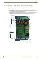
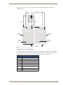
Overview
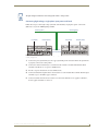
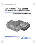
The RE-DM4 RADIA Eclipse 4-Channel Integrated Dimmer Module (120 VAC: FG706-01; 240 VAC:
FG706-02) controls up to six circuits with four 1200-watt onboard dimmers and two satellite connectors
for RDM series dimmer or switch modules. The RE-DM4 is designed for use with the RDA series of
enclosures in an AMX Lighting™ modular digital dimming system. The RE-DM4 is controlled by
AXLink or by dry (contact) closures.
Mounting
points
Power
Devices
Jumper
Line In
Neutral
High
Voltage
Connections
Load out
Chokes
Class 1 wiring
Class 2 wiring
4-Pin Connectors
to RDM series
Modules
AXLink
Address
DIP Switch
Mounting
points
AXlink Connector
Dry Closures
External +12V
Aux Power
FIG. 1 RE-DM4 4-channel Integrated Dimmer Module
RE-DM4 and RE-DM6 RADIA Eclipse Dimmer Modules
1
Radia Eclipse RE-DM4 Dimmer Module
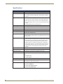
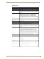
Specifications
RE-DM4 Specifications
Dimensions (HW)
5.75" x 10.0" (146.50 mm x 254.00 mm)
Line Input
• 120, 240 VAC, single phase, 2W+G, 50/60 Hz, 2400 W, one feed
• 120, 120/240, 240 VAC, single phase, 3W+G, 50/60 Hz, 4800 W,
dual feed
Output
• 1200 W max. per channel @120, 240 VAC
• 2400 W max. total, all four channels on with single 2400 W feed
• 4800 W max. total, all four channels on with dual 2400 W feeds
• Line input #1 goes to dimmer 1 and 3; line input #2 goes to dimmer
2 and 4
• All electrical ratings are for continuous duty
Wire rating
Use only copper wires rated at 75°C (167°F) min.
Torque terminals
To 20 in-lbs (2.3 N/M)
Maximum wire size
10 AWG (4 mm²)
Wire stripping length
0.5" (13 mm)
AXLink Port
4-pin 3.5mm black captive wire connector. AXLink communication
signaling with 12VDC power in.
Aux Power
2-pin 3.5mm green captive wire connector. This is a 12VDC power
input that supplies additional power to the Radia PCB and connected
Radia modules.
Dry Contacts
• Emergency fire alarm relay connection - Closed relay activates
preset 126. Other control is locked out until relay opens. Supports
daisy chaining of up to 20 dimmers for this connection, with a
maximum current requirement of 200mA when daisy-chained.
• Failsafe connection - Works with a toggle switch - opening the
switch triggers preset 128, closing the switch triggers preset 127.
Supports daisy chaining of up to 20 dimmers for this connection
with a maximum current requirement of 200mA when daisychained.
BTU/hr
300 single feed (2400 W); 600 dual feed (4800 W)
Idle current draw
75 mA @ 120 VAC, 50 mA @ 240 VAC, 100 mA VDC
RDM control current
2 at 200 mA @ 12 VDC with no additional power supply
Certifications
• FCC
• CE
• IEC-60950 Safety
• UL North America
Operating Temp Range
• 0° to 40°C (32° to 104°F)
Included Accessories
• 2 4-pin 3.5mm captive wire connector (41-5047)
• 4 #8-32x1/2” F-point mounting screws
Required Enclosures
• RDA-ENC2 (FG606-10)
• RDA-ENC4 (FG606-11)
• RDA-ENC6/6B (FG606-12/13/15)
• RDA-ENC12B (FG606-14/16)
2
RE-DM4 and RE-DM6 RADIA Eclipse Dimmer Modules
Radia Eclipse RE-DM4 Dimmer Module
Suggested Loads
Dimmed
Switched
Incandescent
Motors
Neon, cold-cathode
Fans
Caution: Pre-Installation Notes
This unit should be installed only by qualified electrical personnel, and in compliance
with all national electrical codes, local codes and ordinances.To prevent possible
personal injury or death, disconnect power to the enclosure at the breaker box
before attempting to work with any AMX Lighting modules.
zAll Class 1 and 2 wiring must be connected to their dedicated terminals.
zClass 1 wiring should be connected through the top of the enclosure, and Class 2 wiring
through the bottom.
zLoad conductors must be same size as line conductors, regardless of
connected load.
zDisconnect power while installing or connecting the unit.
zKeep top and bottom air vents clear at all times, and maintain 12” (30.48 cm) clearance around
the top and bottom.
zTest loads for shorts before connecting.
zClass 2 wiring must be rated 300V or higher.
zFor indoor use only.
zAC lighting loads only.
zThis module may require extra power from the AXLink connection or an external power
supply connected to the control card.
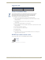
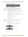
RE-DM4 4-pin module connector (male)
The 4-pin male module connector for the RE-DM4 is illustrated in FIG. 2.
Pin 4 (GND)
Pin 3 (RLY)
Pin 2 (DIM)
Pin 1 (+12 V)
FIG. 2 4-pin Male Module Connector for the RE-DM4
RE-DM4 and RE-DM6 RADIA Eclipse Dimmer Modules
3
Radia Eclipse RE-DM4 Dimmer Module
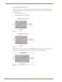
Line-In Connections
zUsing two feeds for Line 1 and Line 2 provides two 2400 W inputs.
zWith a jumper, Line 1 and Line 2 provides a single 2400 W input.
Dual 2400 W Inputs without jumper
Single 2400 W Input with jumper
FIG. 3 Line-In Connections for the RE-DM4
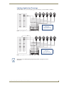
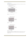
Lighting Application Drawings
The RE-DM4 has two preferred lighting application methods, as shown in FIG. 4 and FIG. 5
Example A
Single input
120 or 240 VAC 1Ø
Single-phase, four load
FIG. 4 Lighting Application for the RE-DM4, Example A
4
RE-DM4 and RE-DM6 RADIA Eclipse Dimmer Modules
Radia Eclipse RE-DM4 Dimmer Module
Example B
Dual Input
120, 120/240, or 240 VAC 1Ø
Single-phase, four load
FIG. 5 Lighting Application for the RE-DM4, Example B
Please refer to the AMX Lighting Programming section on page 37 for more
information.
RE-DM4 and RE-DM6 RADIA Eclipse Dimmer Modules
5
Radia Eclipse RE-DM6 Dimmer Module
Radia Eclipse RE-DM6 Dimmer Module
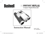
Overview
The RE-DM6 6-Channel Integrated Dimmer Module (120V: FG706-03; 240V: FG706-04) controls up
to six circuits with six 1200-watt onboard dimmers (FIG. 6).
The RE-DM6 is designed for use with the RDA series of enclosures, in an AMX Lighting™ modular
digital dimming system. The RE-DM6 is controlled by AXLink or by dry (contact) closures.
Mounting points
Power Devices
Line In
Jumper
Neutral
High
Voltage
Connections
Load Out
Chokes
Class 1 wiring
Class 2 wiring
AXLink Address
DIP Switch
Mounting points
AXLink Connector
Dry Closures
External +12 V
Aux Power
FIG. 6 RE-DM6 6-channel Integrated Dimmer Module
6
RE-DM4 and RE-DM6 RADIA Eclipse Dimmer Modules
Radia Eclipse RE-DM6 Dimmer Module
Specifications
RE-DM6 Specifications
Dimensions (HW)
5.75" x 10.0" (146.05 mm x 254.00 mm)
Weight
4.5 lbs (2.04 kg)
Line input
• 120, 240 VAC, single phase, 2W+G, 50/60 Hz, 2400 W, one feed
• 120, 120/240, 240 VAC, single phase, 3W+G, 50/60 Hz, 4800 W, dual
feed
Output
• 1200 W max. per channel @120, 240 VAC
• 2400 W max. total, all 6 channels on with single 2400 W feed
• 4800 W max. total, all 6 channels on with dual 2400 W feeds
• Line input #1 goes to dimmer 1, 3, and 5; line input #2 goes to dimmer 2,
4 and 6
• All electrical ratings are for continuous duty
Wire rating
Use only copper wires rated at 75°C (167°F) min.
Torque terminals
To 20 in-lbs (2.3 N/M)
Maximum wire size
10 AWG (4 mm²)
Wire stripping length
0.5" (13 mm)
AXLink Port
4-pin 3.5mm green captive wire connector - AXLink
communication signaling with 12VDC power in.
Aux Power
2-pin 3.5mm green captive wire connector. This is a 12VDC power input
that supplies additional power to the Radia PCB and connected Radia
modules.
Dry Contacts
• Emergency fire alarm relay connection - Closed relay activates preset
126. Other control is locked out until relay opens. Supports daisy
chaining of up to 20 dimmers for this connection, with a maximum
current requirement of 200mA when daisy-chained.
• Failsafe connection - Works with a toggle switch - opening the switch
triggers preset 128, closing the switch triggers preset 127. Supports
daisy chaining of up to 20 dimmers for this connection with a maximum
current requirement of 200mA when daisy-chained.
BTU/hr
300 single feed (2400 W); 600 dual feed (4800 W)
Idle current draw
75 mA @ 120 VAC, 50 mA @ 240 VAC, 100 mA VDC
Certifications
• FCC
• CE
• IEC-60950 Safety
• UL North America
Operating Temp Range
Included Accessories
0° to 40°C (32° to 104°F)
• 2 4-pin captive 3.5mm wire connectors (41-5047)
• 4 #8-32x1/2” F-point mounting screws
Required Enclosures:
• RDA-ENC2 (FG606-10)
• RDA-ENC4 (FG606-11)
• RDA-ENC6/6B (FG606-12/13/15)
• RDA-ENC12B (FG606-14/16)
RE-DM4 and RE-DM6 RADIA Eclipse Dimmer Modules
7
Radia Eclipse RE-DM6 Dimmer Module
Suggested Installation Loads
Dimmed
Switched
Incandescent
Motors
Neon, cold-cathode
Fans
Caution: Pre-Installation Notes
This unit should be installed only by qualified electrical personnel, and in compliance
with all national electrical codes, local codes and ordinances. To prevent possible
personal injury or death, disconnect power to the enclosure at the breaker box
before attempting to work with any AMX Lighting modules.
zAll Class 1 and 2 wiring must be connected to their dedicated terminals.
zClass 1 wiring should be connected through the top of the enclosure, and Class 2 wiring
through the bottom.
zLoad conductors must be same size as line conductors, regardless of connected load.
zDisconnect power while installing or connecting the unit.
zKeep top and bottom air vents clear at all times, and maintain 12” (30.48 cm) clearance around
the top and bottom.
zTest loads for shorts before connecting.
zClass 2 wiring must be rated 300V or higher.
zFor indoor use only.
zAC lighting loads only.
To prevent possible personal injury or death, disconnect power to the enclosure at
the breaker box before attempting to install any AMX Lighting modules.
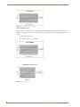
Line-In Connections
zUsing two feeds for Line 1 and Line 2 provides two 2400 W inputs.
zJumping Line 1 and Line 2 provides a single 2400 W input (FIG. 7)
Dual 2400 W Inputs without jumper
Single 2400 W Input with jumper
FIG. 7 Line-In Connections for the RE-DM6
8
RE-DM4 and RE-DM6 RADIA Eclipse Dimmer Modules
Radia Eclipse RE-DM6 Dimmer Module
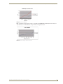
Lighting Application Drawings
The RE-DM6 has two preferred lighting application methods, as shown in FIG. 8 and FIG. 9.
Example A
Single Input
120 or 240 VAC 1Ø
Single-phase, six load
FIG. 8 Lighting Application for the RE-DM6, Method A
Example B
Dual Input
120, 120/240 VAC
Single-phase, six load
FIG. 9 Lighting Application for the RE-DM6, Method B
Please refer to the AMX Lighting Programming section on page 37 for more
information.
RE-DM4 and RE-DM6 RADIA Eclipse Dimmer Modules
9
Radia Eclipse RE-DM6 Dimmer Module
10
RE-DM4 and RE-DM6 RADIA Eclipse Dimmer Modules
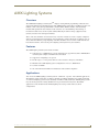
AMX Lighting Systems
AMX Lighting Systems
Overview
The AMX Radia Lighting Control SystemTM employs a dual-platform programming architecture that
supports the NetLinx programming language. The AMX Lighting product line is modular by design, and
includes a wide variety of integrated dimmer control modules, dimmer modules, and switch/relay
modules. This product line also includes circuit cards that can control dimming and switching of
incandescent, fluorescent, and neon (cold-cathode) bulbs; high- and low-voltage equipment; loads
(motors); and electronic and magnetic ballasts.
These cards and controllers can be housed in any of our five enclosures to ensure complete compliance
with any spacing/application requirements. Once the lighting control requirements are defined, you can
choose from the extensive group of lighting controllers, modules, and accessories, install them into the
best-suited enclosures, and create the perfect lighting control system for your customers.
Features
The AMX Lighting Control System features include:
zControl of up to 1,500 dimmers or 255 6-channel devices (approximate) with a AMX NetLinx
Control System complete with dimmer-level feedback
zSupport for 128 lighting scene presets
zRecall of up to 3 of 128 presets with two contact closures: emergency and failsafe
zModular and scalable lighting system configurations of one to 1,500 dimmers
zControl via AXlink
zUL and C-UL listed modules for United States and Canadian compliance
Applications
You can use the AMX Lighting Control System for commercial, corporate, and residential applications.
The NetLinx control architecture can address virtually any number of lighting zones. Entire residential
or commercial lighting systems may be manually controlled or fully automated. AMX Lighting systems
may also be integrated into existing NetLinx/Axcess presentation/control systems. Residential
applications can be divided into inter-linked lighting zones using central and local control
configurations.
RE-DM4 and RE-DM6 RADIA Eclipse Dimmer Modules
11
AMX Lighting Systems
AMX Lighting Control Equipment
The following table lists all of the AMX Lighting Control System equipment currently available. Refer
to the installation sheets for these enclosures, control modules, and dimmer modules for detailed wiring
drawings, application notes, and specifications.
AMX Lighting Control Equipment
AMX Lighting enclosures
RDA-ENC2
2-module enclosure for single-phase dimmer modules
RDA-ENC4
4-module enclosure for dimmer modules
RDA-ENC6
6-module enclosure for single-phase dimmer modules
RDA-ENC6B
6-module, 6-breaker (20 A each) enclosure for multi-phase wiring for one RDC-PDC module
(two or three phase configuration)
RDA-ENC12B 6-module, 12-breaker (20 A each) enclosure that supports multi-phase wiring for two RDCPDC modules
Control cards
RDC-DC
6-channel, single-phase control card (120 or 240 VAC)
RDC-PDC
6-channel, three-phase dimmer control card (120 or 240 VAC)
Integrated dimmer control modules
RE-DM4
4-channel integrated dimmer control module (120 or 240 VAC)
RE-DM6
6-channel integrated dimmer control module (120 or 240 VAC)
Dimmer modules
RDA-CKM
Dual Choke module (350 µS)
RDA-PSM
Power supply module
RDM-2DC
Dual VDR module (2400 W x 2, 0-12 VDC)
RDM-2FDB
Dual FDB Module, 1920 W (x2)
RDM-2INC
Dual incandescent dimming module (2400 W x 2)
RDM-2SWM
Dual switch module (2400 W)
RDM-2ZC
Dual zero cross module (2400 W)
RDM-3FDB
Triple FDB module (2400 W x 3)
RDM-3EM
Heavy Duty Energy Management Relay Module, 20A (x3)
RDM-6EM
Heavy Duty Energy Management Relay Module, 20A (x6)
RDM-3SWM
Triple switch module (20 A x 3)
RDM-DC
DC Module, 1920 W, 0-12 VDC
RDM-2DC
Dual DC dimmer module, 1920 W, 0-12 VDC (x2)
RDM-3DC
Triple DC dimmer module, 1920 W, 0-12 VDC (x3)
RDM-FDB
FDB Module, 1920 W
RDM-HDC
Heavy-Duty DC Module, 2400 W, 0-12 VDC
RDM-HFDB
Heavy duty FDB module (20 A)
RDM-INC
Incandescent dimming module (2400 W)
RDM-INC50
Incandescent dimming module (6000 W)
RDM-MDM
Multimode dimming module (2400 W/20 A)
RDM-SWM
Switch module (2400 W)
RDM-ZC
Zero-cross module (2400 W)
RDM-ZC50
Zero-cross module (6000 W)
Dimmer Accessories
12
RDA-PSM
12 VDC 2.5A Power Supply Module
RDA-CKM
Dual Choke Module
RE-DM4 and RE-DM6 RADIA Eclipse Dimmer Modules
AMX Lighting Systems
AMX Lighting Control Equipment (Cont.)
RDA-DIV
Radia Module Divider
RDA-EFP
Radia Enclosure Filler Plate
RE-DM4 and RE-DM6 RADIA Eclipse Dimmer Modules
13
AMX Lighting Systems
14
RE-DM4 and RE-DM6 RADIA Eclipse Dimmer Modules
Installation
Installation
Space Requirements
AMX Lighting control installations require very little space. Space for enclosures is the main concern.
All enclosures are mounted flush on a vertical surface, and must have a minimum clearance of 12"
(304.8 mm) above and below to allow for air circulation. Physical dimensions for each enclosure are
described in the Enclosure Dimensions section on page 17.
Wiring Considerations
The following information relates to wiring considerations for a AMX Lighting system.
Disconnect power to the device at the breaker box until the wiring is complete.
Preparing/connecting captive wires
1. Strip 0.25 inch of wire insulation off all wires.
2. Insert each wire into the appropriate opening on the connector according to the wiring diagrams and
connector types described in this section.
Do not tighten the screws excessively. Doing so may strip the threads and damage
the connector.
AXLink wiring between multiple devices
FIG. 10 shows AXLink wiring between AXLink devices.
DEV.#3
DEV.#2
DEV.#1
PWR
PWR
P+
P+
AXP
P+
AXP
M-
AXM
M-
AXM
M-
AXP
AXM
GND
GND
PWR
GND
FIG. 10 Multiple AXLink wiring connections
Disconnect the main power to the AMX Lighting controller at the breaker box if rewiring the
AXLink cables.
Power considerations
The following information relates to wiring considerations for an AMX Lighting system.
AXLink connections
In order to establish an AXLink connection for programming, the controller must be connected to a
power source and be powered on. The AMX Lighting system will allow programming after power has
been applied. Once power has been applied and the AMX Lighting controller has established an AXLink
RE-DM4 and RE-DM6 RADIA Eclipse Dimmer Modules
15
Installation
connection, the 12VDC supply to the processor will allow program changes if the 120VAC supply is cut
off.
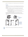
Conduit
Conduit runs depend on the enclosures you use and their AMX Lighting modules. All enclosures have
conduit knockouts on the top for high-voltage connections, and knockouts on the bottom for low-voltage
connections.
All conduit knockouts allow for 1/2, 3/4, and 1-inch (12.7 mm, 19.0 mm, and 25.4 mm) conduits as
shown in FIG. 11. You should also consider these recommendations prior to installing enclosures:
zInstall separate conduit for lighting loads. The recommended knockout for loads is located on
the top center of the enclosure.
zInstall separate conduit for the 120 VAC wiring to the line input terminal block. The
recommended knockouts for incoming power feeds are located on the top-left and top-right
sides of the AMX Lighting enclosure.
Install separate conduit for low-voltage signals for dry closures and AXLink connections. The
recommended knockout for these control connections is located on the bottom of the enclosure.
Additional knockouts are on the bottom-left and bottom-right sides of the enclosures for alternate lowvoltage connections.
C
TOP
A
Knockout
B
Knockout
A
All knockouts
are for 1/2" (1.26 cm),
3/4" (1.90 cm), and
1" (2.54 cm)
conduit
BOTTOM
C
A
A
Knockout
F
Knockout
D
D
LEFT SIDE
E
G
Knockout
E
FRONT
RIGHT SIDE
A = 3.94" (100.0 mm)
B = 6.03" (153.1 mm)
C = 3.00" (76.2 mm)
D = 1.00" (25.4 mm)
E = 9.75" (24.76 cm)
F = 6.00" (15.24 cm)
G = 11.90" (30.22 cm)
Knockout
FIG. 11 Knockout locations (RDA-ENC2 used as example)
Install the control modules according to local and National Electrical Code (NEC) regulations.
16
RE-DM4 and RE-DM6 RADIA Eclipse Dimmer Modules
Installation
Enclosure Dimensions
RDA-ENC2, -ENC4, and -ENC6 enclosure and dimensions
FIG. 12 shows the dimensions for the RDA-ENC2, RDA-ENC4, and RDA-ENC6 enclosures.
RDA-ENC2
RDA-ENC4
0.75"
(19.05 mm)
RDA-ENC6
6.0"
(152.4 mm)
Top View
Side View
(for all enclosures)
Internal
View
12.0"
(304.8 mm)
Bottom
View
6.0"
(152.4 mm)
12.0"
(304.8 mm)
18.0"
(457.2 mm)
FIG. 12 RDA-ENC2, RDA-ENC4, and RDA-ENC6 enclosure dimensions
RDA-ENC6B and RDA-ENC12B enclosures and dimensions
FIG. 13 shows the dimensions for the RDA-ENC6B and RDA-ENC12B enclosures.
0.75"
(19.05 mm)
TOP VIEW
6.0"
(152.4 mm)
Note:
LINE INPUTS: 140 A MAX PER ENCLOSURE
Use 75° C copper conductors only.
Torque terminals to 44 in-lbs.
SIDE VIEW
RDA-ENC6B
24.0"
(61.0 mm)
24.0"
(61.0 mm)
RDA-ENC12B
Not included
with enclosures
18.0"
(457.2 mm)
Top, side, and bottom
views are the same for
both enclosures.
BOTTOM VIEW
FIG. 13 RDA-ENC6B and ENC12B enclosures and dimensions
RE-DM4 and RE-DM6 RADIA Eclipse Dimmer Modules
17
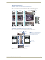
Installation
Mounting AMX Lighting Enclosures
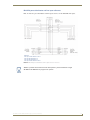
AMX Lighting enclosures must be mounted on a vertical surface with a minimum of 12" (304.8 mm)
clearance above and below the enclosure. FIG. 14 shows the centerline reference points and dimensions.
The clearance above and below the enclosure is necessary for proper ventilation and
heat dissipation.
1. Remove the front cover by removing the screws at the bottom of the enclosure; two tabs suspend the
cover from the top.
2. Position the enclosure on the wall so that it is level, with the high-voltage terminals of the unit at the
top.
3. Mark the four mounting holes according to the dimensions shown in FIG. 14.
4. Install screws at the marks. The maximum screw size is #12.
5. Hang the enclosure on the four screws and then tighten the screws.
Refer to the Dimmer Enclosures with Breakers installation guide for more
information.
Configuration for
right and left
mounting brackets
for all Radia
enclosures.
A to B
Top slot
B to C
Maximum mounting
screw size: #12
Distance: A to B:
RDA-ENC2 - 5.25" (133.3 mm)
RDA-ENC4 - 10.0" (254.0 mm)
RDA-ENC6 - 16.0" (406.4 mm)
RDA-ENC6B - 16.0" (406.4 mm)
RDA-ENC12B - 16.0" (406.4 mm)
Distance: B to C:
RDA-ENC2 - 11.0" (279.4 mm)
RDA-ENC4 - 11.0" (279.4 mm)
RDA-ENC6 - 11.0" (279.4 mm)
RDA-ENC6B - 22.88" (581.2 mm)
RDA-ENC12B - 22.88" (581.2 mm)
Bottom slot
FIG. 14 Center-line reference points and dimensions
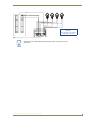
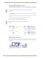
High-Voltage Connections
FIG. 15 shows an example of a high-voltage connection for an RE-DM4 controller. Each AMX Lighting
module has its high-voltage connectors marked on its circuit board. Line, load, and neutrals are also
clearly marked.
Load
Line in
Load
Neutral
FIG. 15 High-voltage connections for an RE-DM4
18
RE-DM4 and RE-DM6 RADIA Eclipse Dimmer Modules
Installation
All high-voltage connections must comply with Class 1 wiring codes.
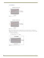
Connecting high-voltage, single-phase input power and loads
Follow these steps to wire high-voltage (120 VAC and 240 VAC), single-phase power connections
(FIG. 16) to any of the AMX Lighting modules.
Ground (green)
Hot (black)
Ground (green)
Hot (black)
Neutral (white)
Neutral (white)
to Enclosure
ground terminal
FIG. 16 RE-DM4 and RE-DM6 (as examples only) high-voltage, single-phase power connections for line input (hot),
neutral, and ground.
1. Connect the green ground wire(s) to the copper ground lug on the enclosure. Ensure the ground wire
is properly connected to earth ground.
2. Connect the white neutral wire(s) to a terminal on the enclosure's neutral terminal block. Each
terminal on the block can accept two 10 AWG wires.
3. Provide a separate neutral wire for each dimmed zone.
4. Connect the black line input from the electrical devices to the module's line terminal. The line input
terminal accepts a 10 AWG copper conductor.
5. Connect load lines from the electrical devices to the Load terminals. Load 1 applies to dimmer 1,
Load 2 applies to dimmer 2, and so on.
RE-DM4 and RE-DM6 RADIA Eclipse Dimmer Modules
19
Installation
RDA-ENC6B 120 VAC single phase line input
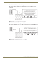
FIG. 17 shows a 120 VAC single-phase (2 W + G) wiring diagram for the RDA-ENC6B line input
terminal block.
1
2a
2b
3
FIG. 17 RDA-ENC6B 120 VAC single-phase (2 W + G) wiring diagram
RDA-ENC6B 120/240 VAC line input (single phase)
FIG. 18 shows a 120/240 VAC single-phase (3 W + G) wiring diagram for the RDA-ENC6B line input
terminal block.
1
2a
2b
3
FIG. 18 RDA-ENC6B 120/240 VAC single-phase (3 W + G) wiring diagram
20
RE-DM4 and RE-DM6 RADIA Eclipse Dimmer Modules
Installation
Connecting high-voltage input power and loads
Follow these steps to wire high-voltage (120 VAC and 240 VAC) power connections (FIG. 19) to any of
the AMX Lighting modules
Connect to neutral block
RDA-ENC6B
line input terminal
1
2a 2b
3
These
connections
are factorywired
FIG. 19 High-voltage, three-phase input power
1. Connect the green ground wire(s) to the copper ground lug on the enclosure. Ensure the ground wire
is properly connected to earth ground.
2. Connect the white neutral wire(s) to one of the terminals on the enclosure's neutral terminal block.
3. Provide a separate neutral wire for each controlled zone.
4. Connect the black line input from the electrical panel to the enclosure's line terminal. The line input
terminal accepts a 0 AWG copper conductor.
5. Connect load lines from the electrical devices to the Load terminals. Load 1 applies to dimmer 1,
Load 2 applies to dimmer 2, and so on.
RDA-ENC6B 120/208 VAC line input (three phase)
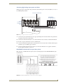
FIG. 20 shows a 120/208 VAC three-phase (4 W + G) wiring diagram for the RDA-ENC6B line input
terminal block.
1
2a
2b
3
FIG. 20 RDA-ENC6B 120/208 VAC three-phase (4 W + G) wiring diagram
RE-DM4 and RE-DM6 RADIA Eclipse Dimmer Modules
21
Installation
While it is possible to wire the enclosure with 3-phase Y, please remember a single
RE-DM4 or RE-DM6 will only support one Y-phase.
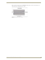
RDA-ENC6B three phase line input connector reference
FIG. 21 shows a sample RDA-ENC6 three phase (4 W + G) line input connector and dimmer references.
1
2a
2b
3
Line input 1 feeds dimmers 1 and 4
Line input 2a feeds dimmer 5
Line input 2b feeds dimmer 2
Line input 3 feeds dimmers 3 and 6
FIG. 21 RDA-ENC6B three-phase (4 W + G) line input connector and dimmer references
22
RE-DM4 and RE-DM6 RADIA Eclipse Dimmer Modules
Installation
RDC-PFC power distribution and line input references
FIG. 22 shows the power distribution and line input references for the RDC-PFC line inputs.
RDC-PFC
Line input 1 feeds dimmers 1 and 4
Line input 2a feeds dimmer 5
Line input 2b feeds dimmer 2
Line input 3 feeds dimmers 3 and 6
FIG. 22 RDC-PFC power distribution and line input reference references
While it is possible to wire the enclosure with 3-phase Y, please remember a single
RE-DM4 or RE-DM6 will only support one Y-phase.
RE-DM4 and RE-DM6 RADIA Eclipse Dimmer Modules
23
Installation
Installing RDM Modules into an Enclosure
Installing any of the RDM modules is an easy task. The individual modules are shipped with the four
mounting screws enclosed.
To prevent possible personal injury or death, disconnect power to the enclosure at
the breaker box before attempting to install any AMX Lighting modules.
FIG. 23 illustrates the inside of an RDA-ENC6 enclosure and the mounting slots. The modules are
positioned in the appropriate slot and secured using the supplied screws.
Neutral terminal block
Ground terminal block
Mounting screw
holes for modules
(4 per slot)
Module mounting slots
FIG. 23 Enclosure module mounting slots and mounting screw holes
The RE-DM4 and RE-DM6 take up 2 Radia enclosure slots each, so an RDA-ENC6
can hold only three RE-DM4/RE-DM6 devices.
The RDA-ENC2 enclosure contains a ground-terminating lug. The RDA-ENC4, RDA-ENC6, RDAENC6B, and RDA-ENC12B enclosures contain a neutral terminating block and a ground-terminating
lug.
24
RE-DM4 and RE-DM6 RADIA Eclipse Dimmer Modules
Installation
Low-Voltage Connections
All low-voltage connections must comply with Class 2 wiring codes.
The low-voltage area in the AMX Lighting controllers contain connections and DIP switches for
AXLink, dry closures, and module jack connectors. On the controller cards, low-voltage power for the
board is supplied either by line power, optional auxiliary power supply (RDA-PSM), or the +12 VDC pin
on the AXLink connector. The green status LED on the controller circuit board also blinks, according to
the current operating status of AXLink and red LEDs, one for each of the external connectors for
additional modules. FIG. 24 shows an example of the low-voltage connections, DIP switches and LEDs
using the RE-DM4 controller.
Module connector/LED (CH6)
Module connector/LED (CH5)
AXLink address DIP switch
AXlink connector
Dry contact closures
Auxiliary power IN
FIG. 24 Low-voltage connections and DIP switches
Module connections
When connecting a dimming/switching module to a AMX Lighting controller, connect it as shown in
FIG. 25.
Pin 4 (GND)
Pin 3 (RLY)
Pin 2 (DIM)
Pin 1 (+12V)
4-pin module connector
on AMX Lighting controller
3 (-)
4-pin plug from RDM-controller
module
1 (+)
The 4-pin plug from the module connects to a 4-pin
connector on the controller module with the black
cover facing upwards.
FIG. 25 Module connection to a controller card
RE-DM4 and RE-DM6 RADIA Eclipse Dimmer Modules
25
Installation
Green status LED indicator
When you apply power to the AMX Lighting Control System, the green status LED notes its conditions:
zIt is on full when AC power is applied to the control module, and no Axlink communication is
present.
zIt blinks on and off when AC power is applied to the control module, and Axlink
communication is present.
zIt blinks on and off rapidly when no AC power is applied to the control module, and the board
is powered via Axlink or Aux In DC power.
The LED indicator is located above the low voltage terminal, in the lower section of the control module.
Red status LED indicators (RE-DM4 only)
The red LED's function is to indicate level. LED brightness increases as signal level increases from zero
to 100. The LED indicator is located above each external load connector jack on the control module.
Configuring and connecting multiple controllers
Since the Radia RE-DM4 and RE-DM6 differ from other AMX lighting controllers by not having a SW2
DIP switch, the "All Lights On" installer test is invoked by turning OFF all 8 switches on SW1.
1. Power off the AMX Lighting enclosure at the breaker panel.
2. Locate the SW1 DIP switch on the controller circuit card, and set the pack number using the values
shown in the preceding table. The pack number must be 1 to 10.
All Radia dimmers are Pack 1. This cannot be changed.
26
RE-DM4 and RE-DM6 RADIA Eclipse Dimmer Modules
Installation
FIG. 26 shows an example of how to interconnect two AMX Lighting RE-DM4 controllers and a
AXLink wall panel.
Neutral
HOT (1)
Neutral
HOT (2)
RE-DM4
(pack 1)
RE-DM4
(pack 1)
AXLink
connector
AXLink
connector
(black)
(black)
AXLink
FIG. 26 AXLink configuration sample
Configuring and connecting AXLink
On all AMX Lighting controllers, DIP switch SW1 sets the AXLink device number. The device number
is determined by the value of all the switch position settings. The following table shows the SW1 DIP
switch positions and their values. The device number assignment range is 1 through 255.
SW1 DIP switch setting values for AXLink
Position
Value
1
1
2
2
3
4
4
8
5
16
6
32
7
64
8
128
RE-DM4 and RE-DM6 RADIA Eclipse Dimmer Modules
27
Installation
Turning off all switches invokes "Installer Test Mode": all lighting circuits at 100%.
1. Power off the enclosure unit at the breaker panel.
2. Locate the SW1 DIP switch (AXLink ADDRESS) on the controller circuit card and set the device
number, using the values shown in the proceeding table.
3. Connect the four-pin AXLink male connector into the four-pin female AXLink connector on the
controller circuit card. FIG. 27 shows how to wire the AXLink connector to a Central Controller
system.
(optional)
+12V
+12V
AXP/TX
AXM/RX
AXP
AXM
GND
GND
AXLink connector
Central Controller
FIG. 27 AXLink wiring diagram
4. Apply power to the controller module at the breaker panel.
5. Radia v3.xx and higher constantly read the AXlink address switch. Power does not need to be reset
or cycled after changing the AXlink address.
External power
The following table lists the modules that use most of the operating power an AMX Lighting control
module can supply. They may require extra power from the AXLink connection or an external power
supply connected to the control module or module(s) when using multiple modules.
External Modules
RDM-HSW
RDM-MR
RDM-SWM
RDM-2HSW RDM-2MR
RDM-2SWM
RDM-3HSW RDM-3MR
RDM-3SWM
RDM-HFDB RDM-MR35 RDM-DPSM
RDM-HDC
RDM-MR60
If extra power is required, connect an auxiliary 12 VDC power supply as shown in FIG. 28.
+ Auxiliary 12 VDC
power supply
+
-
FIG. 28 Auxiliary power connection
28
RE-DM4 and RE-DM6 RADIA Eclipse Dimmer Modules
Installation
Dry Closures
The RE-DM4 and RE-DM6 have two dry closure inputs via a 4-pin mini-phoenix connector. The inputs
are an open collector pulled up to 5 VDC. The status is normally open, channel Off, with the closure
released. When an input is pulled low to ground and falls below 3 VDC, the AMX Lighting system sees
the action as an input closure, the AXLink channel is turned On, and a push sent to the Axcess Central
Controller.
Connecting dry closures
AMX Lighting controller modules contain four connections for two dry contact closure inputs, and one
common reference point. The Radia has two (2) contact closure inputs dedicated to special purposes:
Failsafe and Emergency.
Failsafe Input
The failsafe input is provided to facilitate limited stand-alone operation in the event that the AXLink
master is no longer functioning. The failsafe input shall function regardless of whether AXLink is
working properly or not (i.e. there is no lockout of control).
Operationally, when the failsafe input contact closure is closed (i.e. ON), preset 128 will be recalled.
When the failsafe input contact closure is opened, preset 127 will be recalled. Both of these preset recalls
occur on the edge of the transition from opened-to-closed to closed-to-opened.
Emergency Input
The emergency input is provided to interface to an alarm system (such as a fire alarm) to set the lighting
to an appropriate state for an emergency (e.g. light the path to the exit). The expected operation of the
alarm system is to hold (close) the contact closure as long as the alarm is active and release (open) the
closure when the alarm is cleared.
Operationally, when the emergency input contact closure is closed (i.e. ON), preset 126 will be recalled.
In addition, all other controls of the lighting functions will be disabled as long as the emergency input is
closed. When the emergency input contact closure is opened, normal operation of the Radia will resume.
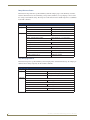
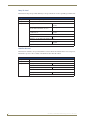
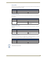
Default Settings
The following tables shows the default low-end settings, default preset time values, default dry-closure
presets and factory presets for AMX Lighting:
Default Low-End Settings
Function
Low-end setting
Channel 1
LE=0
Channel 2
LE=0
Channel 3
LE=0
Channel 4
LE=0
Channel 5
LE=0
Channel 6
LE=0
Default preset time values
Firmware version
2.0 or greater
Function
Time Value
Default ramp time
6
Default level time
1
Default preset time
3
RE-DM4 and RE-DM6 RADIA Eclipse Dimmer Modules
29
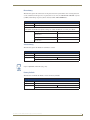
Installation
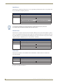
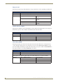
Default Presets
Preset
Number
Description
1
Channel 1, Channel 1 @ 100% in 1 second
2
Channel 2, Channel 2 @ 100% in 1 second
3
Channel 3, Channel 3 @ 100% in 1 second
4
Channel 4, Channel 4 @ 100% in 1 second
5
Channel 5, Channel 5 @ 100% in 1 second
6
Channel 6, Channel 6 @ 100% in 1 second
7
Channels 1-6 @ 100% in 1 second
8
Channels 1-6 @ 0% in 1 second
126
Emergency Dry Closure On
Channel 1-6 @ 100% in 1 second
127
Failsafe Dry Closure Off
Channels 1-6 @ 0% in 1 second
128
Failsafe Dry Closure On
Channels 1-6 @ 100% in 1 second
30
RE-DM4 and RE-DM6 RADIA Eclipse Dimmer Modules
Radia Lighting System Configuration Pages
Radia Lighting System Configuration Pages
Overview
The AMX Radia Web pages provide a simple interface from which an installer/user may perform
lighting system configuration and setup tasks without needing access to an AMX touch panel. The web
pages reside on the AMX master and may be accessed through a compatible Web browser. The AMX
Radia configuration web pages were designed with setup functionality in mind and not everyday control.
The browsers currently supported by the Radia Web pages are Internet Explorer version 6.0 and 7.0 and
Mozilla Firefox version 2.0.0.3.
Use of the AMX Radia Web Pages requires the use of the Radia Duet Module.
NetLinx code or a terminal may also be used to configure the lighting system if use of
the module is not an option.
Lighting System Link
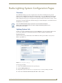
In order to access the configuration web pages for the AMX Radia, open your computer's browser and
point it to the AMX master containing the loaded Duet module by typing the following URL:
http://xxx.xxx.xxx.xxx
where xxx.xxx.xxx.xxx is the IP address of the AMX master. This opens the Master Configuration
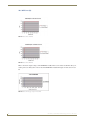
Manager page (FIG. 29).
FIG. 29 Master Configuration Manager
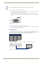
Once the page is loaded:
1. Click on the System menu button at the top of the page.
2. Click the Manage Device tab
3. Expand the Lights node in the Device Configuration Pages section by clicking on the link.
4. Click on the AMX Radia RE-DM4,Radia RE-DM6 - 41001:1:0 link.
RE-DM4 and RE-DM6 RADIA Eclipse Dimmer Modules
31
Radia Lighting System Configuration Pages
The AMX master must be running firmware v3.21.343 or higher for the Radia Eclipse
configuration pages to work as expected.
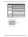
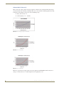
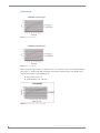
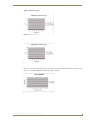
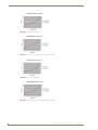
Main Lighting System Page
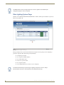
Clicking on the AMX Radia RE-DM4,Radia RE-DM6 - 41001:1:0 link opens the Radia Configuration
Manager page (FIG. 30).
FIG. 30 Radia Configuration Manager
This page displays basic system status information and options for navigating to and configuring a
particular component. The information provided includes:
zthe lighting area Label
zthe component AxLink Address
zthe virtual address used
zthe device or preset model
zthe component status
zthe Configure button for each device to be configured.
The Global Presets listing is a special type of lighting component, since it is always
declared Online and has no AxLink Address associated with that entry.
32
RE-DM4 and RE-DM6 RADIA Eclipse Dimmer Modules
Radia Lighting System Configuration Pages
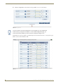
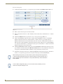
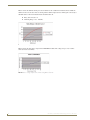
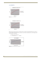
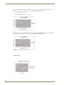
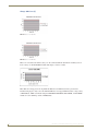
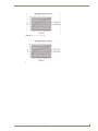
Device Configuration Page
This page provides the ability to name your specific Radia device by typing an installation-specific label
in the Lighting Area Name field (FIG. 31).
FIG. 31 Device Configuration Page
To configure a particular device from the Device Configuration page:
1. In the main Radia Configuration Manager page, click the Configure button.
2. In the Lighting Area Name field, enter a descriptive name for the area.
Although the Lighting Area Name field can accept over 200 characters, choosing a
short but descriptive name for the lighting area is highly recommended.
3. For each dimmer, change the name in the Label field if necessary.
4. For each dimmer, change the Curve selected in the dropdown menu if necessary.
5. For each dimmer, change the level with the Level slidebar if necessary. The field to the right of the
slidebar will display the exact level. Alternately, enter the exact level you wish to have associated
with that dimmer by entering the number into the field to the right of the slidebar, and the slidebar
will move to match the entry.
RE-DM4 and RE-DM6 RADIA Eclipse Dimmer Modules
33
Radia Lighting System Configuration Pages
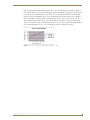
6. Click the Accept button at the bottom of the page (FIG. 32) to save your changes.
FIG. 32 Accept button
You do not need to click the Accept button to save changes if you only adjusted the
dimmer levels by using the Level slidebar. To exit a Radia configuration page, you
must choose Cancel, whether you have chosen to accept the changes or not.
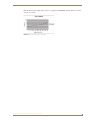
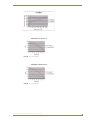
Each Radia device has, by default, 11 predefined presets, also shown on the Device Configuration page
(FIG. 33), that can be modified as well.
FIG. 33 Presets section
34
RE-DM4 and RE-DM6 RADIA Eclipse Dimmer Modules
Radia Lighting System Configuration Pages
To modify an existing preset:
1. In the Device Configuration page, scroll down to the preset to be modified.
2. For more information on the preset, click the Info button for the preset. This opens a new
information box with the preset’s dimmer and level information. When finished, close the box.
3. In the Label field, change the preset’s label if necessary.
4. Select the Preset Time by either moving the slidebar or entering the preset time (1-255) in the field
to the right of the slidebar. If you enter a preset time number higher than 255, the slidebar will move
to the "Max" position.
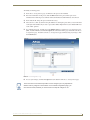
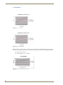
5. To configure the preset, click the preset’s Configure button to open the Preset Configuration page
(FIG. 34). When finished, click the Accept button at the bottom of the page and return to the Device
Configuration page. To return to the Device Configuration page without saving any changes, click
the Cancel button.
FIG. 34 Preset Configuration Page
6. To save your changes, click the Accept button at the bottom of the Device Configuration page.
You do not need to click the Accept button to save changes if you only adjusted the
dimmer levels by using the Level slidebar. To exit a Radia configuration page, you
must choose Cancel, whether you have chosen to accept the changes or not.
RE-DM4 and RE-DM6 RADIA Eclipse Dimmer Modules
35
Radia Lighting System Configuration Pages
To create a new preset:
1. Scroll to the bottom of the Device Configuration page and click the Add Preset button (FIG. 35).
FIG. 35 New Preset button
2. Enter a name for the new preset in the Label field.
3. Enter a time (0-255) in the Preset Time field. If you do not add a time, a default value of "1" will be
entered.
4. Click the Configure button to open the New Preset Configuration page (FIG. 34).
5. Click a desired lighting component in the Available field to highlight it. To move an individual
lighting component into the Stored field, click the ">" button. To move a previously selected
lighting component back to the Available field, click on it in the Stored field and then click the "<"
button. To move all of the lighting components from the Available field to the Stored field, highlight
one component and click the ">>" button. Reverse the process and click the "<<" button to return all
lighting components to the Available field.
6. Clicking the Recall button will recall the preset and the Tweak button will refresh and auto-save the
preset with the current load levels. The Recall and Tweak buttons are only enabled for existing and
saved presets; neither button will be enabled for a new preset that has not been saved.
7. To finalize your changes to the preset, click the Accept button at the bottom of the page. To return to
the Device Configuration page and cancel any unsaved changes, click the Cancel button.
While creating a new preset, you cannot edit any other saved preset during that time,
or the new preset information will be lost. Please create your new preset and save it
before attempting to edit or add others. A new preset without any stored information
will be deleted.
To exit a Radia configuration page, you must choose Cancel, whether you have
chosen to accept the changes or not.
36
RE-DM4 and RE-DM6 RADIA Eclipse Dimmer Modules
AMX Lighting Programming
AMX Lighting Programming
Introduction
This section provides an overview of AMX Radia Eclipse concepts and programming. For detailed
protocol information, please see the Appendix B: Radia Lighting Programming section on page 76.
This section explains firmware, channels, programming commands, and lighting curves.
Software
To best facilitate use of the Radia Eclipse RE-DM4 and RE-DM6, both use a VisualArchitect-ready Cafe
Duet module for communications between a NetLinx master and the Radia unit.
"The Duet module is designed to the DeviceSDK Lighting device class, including:
zRamp lighting levels
zTurn lights on and off
zRecall lighting presets
zStatus feedback for on/off, level and active preset
The Duet module utilizes the master's web servlet to provide a GUI interface for lighting system and
preset configuration, including:
zName zones
zSelect zones
zRamp zones
zDiscrete and toggle on/off
zRecall presets
zSave current preset settings
zUndefine zones for exclusion from preset definition
zSave a lighting scene as a preset on the Radia device and on the NetLinx master preset in a VA
1.2-compatible XML file format.
zTransfer the configuration XML file by uploading from the Radia device to the NetLinx
master, downloading from the NetLinx master to Radia, and uploading from the NetLinx
master to a PC for use in VisualArchitect. The Duet module will provide any conversion
between RADIA format requirements and the XML file format, if necessary
"The Duet module queries the Radia Eclipse device on startup to populate the dimmers attached to the
Radia system, based on its configuration file.
RE-DM4 and RE-DM6 RADIA Eclipse Dimmer Modules
37
AMX Lighting Programming
Presets: Defined vs. Undefined Levels
Understanding the meaning of the terms "defined" and "undefined", as used in the context of levels in a
Radia lighting system, is necessary for properly setting up presets for multiple lighting zones. Each
dimmer on the Radia has a TRUE/FALSE status associated with it that is referred to as "defined". The
state of the defined status is used when saving presets so that the Radia knows which dimmers are to be
affected when the preset is recalled. Upon power-up, all the dimmers are in the undefined state. As soon
as any of the dimmers changes state (i.e. the level changes), the dimmer automatically becomes defined.
Upon recording a preset, the Radia will save all of the dimmer levels that are defined at that time and
only affect those when the preset is recalled.
For example, if all the dimmers are undefined and dimmers 1 and 3 get their levels changed, the Radia
will save the levels of 1 and 3 only when told to record preset 7. When preset 7 is recalled, only dimmers
1 and 3 will be adjusted. The other dimmers (2, 4, 5 and 6) are said to be undefined for that preset.
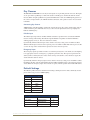
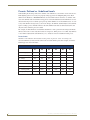
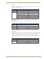
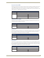
Preset Status
Channels 1-128 reflect the current status of active presets. A preset is "active" for as long as its
associated dimmers (circuits) remain at the levels associated with the preset. For example, assume the
following presets exist in the Radia:
Preset #
Preset #
Dimmer
#1
Dimmer
#2
Dimmer
#3
Dimmer
#4
Dimmer
#5
Dimmer
#6
1 – Meeting (A)
100%
50%
100%
2 – Presentation (A)
50%
25%
50%
3 – Off (A)
0%
0%
0%
4 – Meeting (B)
100%
50%
100%
5 – Presentation (B)
50%
25%
50%
6 – Off (B)
0%
0%
0%
7 – Cleaning (A&B)
8 – Night (A&B)
38
100%
100%
100%
100%
100%
100%
0%
0%
0%
0%
0%
0%
RE-DM4 and RE-DM6 RADIA Eclipse Dimmer Modules
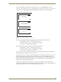
AMX Lighting Programming
Also, the configuration of the Radia is such that dimmers 1-3 are controlling lights in room A (a
conference room) and dimmers 4-6 are controlling lights in room B (another conference room). In each
of these room is a 3-button wall-mounted control panel that provides control of the local lights:
Meeting Mode
Meeting
Mode
Presentation
Mode
Presentation Mode
Off
Off
FIG. 36 Example - 3-button wall-mounted control panel
The room A panel has the following mapping between buttons and presets and feedback:
Meeting Mode -> Preset 1 -> Feedback from channel 1
Presentation Mode -> Preset 2 -> Feedback from channel 2
Off -> Preset 3 -> Feedback from channel 3
The room B panel has a similar mapping between buttons and presets:
Meeting Mode -> Preset 4 -> Feedback from channel 4
Presentation Mode -> Preset 5 -> Feedback from channel 5
Off -> Preset 6 -> Feedback from channel 6
One other panel, used by security, has two buttons to control the lights for Cleaning mode and Night
mode. These buttons recall presets 7 and 8, respectively.
Operationally, room A panel and room B panel should appear to be independent with the currently active
preset feedback active on its associated control panel. If room A is in Presentation Mode, then the
Presentation Mode button LED should be lit (i.e. channel 2 should be on). If room B is in Meeting Mode,
then the Meeting Mode button LED should be lit (i.e. channel 4 should be on), meaning that both
channels 2 and 4 will be on with all others off.
Assuming the conditions above (channels 2 & 4 on), when Cleaning mode is selected by security,
channels 2 and 4 will be turned off and channel 7 will be turned on. Thus, a preset's feedback will remain
on until something affects any one of the dimmers affected by the preset.
RE-DM4 and RE-DM6 RADIA Eclipse Dimmer Modules
39
AMX Lighting Programming
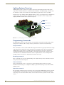
Lighting Systems Overview
AMX Lighting systems are based on a modular construction. The modular structure has three basic
components: Controller, Enclosure, and Dimmer/Switch Modules. All AMX Lighting controllers have
six channels of control. Seven channels of control will always require the use of two controllers.
In order to have the controllers address different dimmers’ ranges, each pack/group of six channels have
a specific range. The packs may be controlled by Cafe Duet code. FIG. 37 shows a sample AMX
Lighting RE-DM4 controller and its internal components.
Power
CH5 connector
CH6 connector
Dry Closure
FIG. 37 Sample AMX Lighting controller and internal components
Programming Commands
The Radia Eclipse system uses four main types of programming commands: Setup, Recording, Status,
and Operation commands. All recording and setup commands are stored in non-volatile memory.
Setup commands
These commands are used to set the default values and parameters that are typically entered at the startup
of the system and not changed. If certain commands are issued with no time value associated then the
AMX Lighting system will use an available default value determined at setup. The commands for
recording and recalling presets use these defaults, as do ramping operations. Curve settings are setup
commands done on a individual channel basis and are not global. Curves can be set during initial
installation and do not need to be changed unless the loads also change.
Recording commands
These commands store preset data in Radia Eclipse non-volatile memory. These commands are used to
store presets and erase stored presets.
Status commands
Status commands allow a user or a program to get data from the lighting system and act on that
information. This feature gives a computer the ability to perform interactive processes with the AMX
Lighting system.
Operation commands
The operational commands category, the largest category used by the AMX Lighting system, is used for
real-time lighting control and setup of scenes prior to programming presets. Operational commands
recall, ramp, and set levels for dimmers. They can also be used for remote operation of the dry closure
contact.
40
RE-DM4 and RE-DM6 RADIA Eclipse Dimmer Modules
AMX Lighting Programming
Control Curves and Low End Settings
The market currently has a great selection of new lamp and ballast options. Each one has properties and
dimming characteristics that present a new challenge for the dimmer manufacturer to provide an
appropriate dimmer. What was designed as a standard incandescent dimmer must now be able to control
electronic ballast, incandescent lamps, low voltage track lighting, and a host of new transformers. One
way to solve many of these problems is to apply different control curves to each dimmer and to provide a
variable low-end cut-off point.
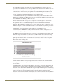
A dimming curve is a graphical or electronic representation of the amount of control that must be applied
to a dimmer in relation to the dimmer output. This is much like a directional map that the controller
follows. The amount of control is typically measured in percent; from an Off-state of level 0 to an Onstate at level 100. Dimmer output is measured in volts. A graphical representation of a dimming curve is
usually the percentage of dimming in relation to the output voltage (RMS) of the dimmer connected to a
standard load. FIG. 38 shows a sample dimming curve.
FIG. 38 Sample dimming curve
Sometimes a fixture or lamp has a problem dimming down to a low range. When this happens, the lights
can flicker and cause unwanted dimming performance. To correct for anomalies in the dimming
performance of various devices, the AMX Lighting controller has provisions to set an individual low-end
trim for each of the six dimming channels. The AMX Lighting dimming system employs a low-end cutoff that allows the dimmer to turn on to a specified level or to dim down to a specific level. The level at
which the dimmer turns on is called the Low End Setting. Low End commands prevent the dimmer from
going below a set threshold. They also force the dimmers on to the preset threshold, which is useful for
some transformer loads and track lights.
RE-DM4 and RE-DM6 RADIA Eclipse Dimmer Modules
41
AMX Lighting Programming
42
RE-DM4 and RE-DM6 RADIA Eclipse Dimmer Modules
Appendix A: AMX Lighting Curves
Appendix A: AMX Lighting Curves
Overview
Thousands of different lighting fixtures with unique shapes and styles exist, all designed to do something
visibly different with light. Any one of those fixtures in a hundred different locations could produce a
different lighting effect. Two identical lights in different locations could produce different reflections and
shadows.
For instance, consider a situation where low-voltage track lights are mixed with compact fluorescent
down lights to illuminate a hallway with pictures. Under normal dimming conditions, the two different
light sources would dim differently and possibly require individually set dimmers to accomplish uniform
lighting at different levels. An Up or Down button on a wall control panel would dim both sources at a
common rate, but the lamps and fixtures would dim at different rates due to the lamp and ballast
characteristics. The track light may stay bright for an extended period and then rapidly dim to nothing
while the fluorescent lamp dims smoothly to a point and then abruptly shuts off. The combined effect
produces an uncoordinated scene change.
An unwanted feature of dimmable fluorescent ballasts and low-voltage electronic transformers is their
tendency to cause the lamps to flicker when dimmed to low levels. The normal way to avoid this is to use
presets that are not dimmed below the fixture's threshold or to use any low end trim feature provided by
the ballast or transformer manufacturer. Problems arise when the performance of the dimmer does not
match the performance of the dimmable ballast. The AMX Lighting system now gives the user the
ability to change the performance of the dimmer to avoid problems.
Many types of track lights and dimmable ballast only have a limited dimming range for the dimmer to
work with. In a dimming range of 0 to 120 volts AC, many lamps do not start to dim until fewer than 100
volts is applied. Lamps often do most of their dimming between 40 and 100 volts. Dimmers designed to
increment voltages from 0 to 120 volts can be wasted on lamps that do not even respond to 50% of the
dimmer's output. Some lamps are more sensitive to voltage changes at the low end and can accommodate
many degrees of dimming, but standard dimmers tend to rush past the lamp's sensitive range and
occasionally linger in an unusable range.
Slowly turning a lamp on can be a very different effect than slowly dimming that same lamp off. Some
light sources require a minimum level to turn on. Once these lamps are on, they can be dimmed down to
lower light levels. At the same time, most common dimmers are built to dim at a uniform rate, regardless
of the individual characteristics of each lamp or the number of lamps.
The properties and dimming characteristics of each new lamp and ballast on the market present a new
challenge to the dimmer manufacturer to provide an appropriate dimmer. What was designed as a
standard incandescent dimmer must now be able to control electronic ballasts, incandescent lamps,
transformered low-voltage track lighting, and a host of electronic transformers.
One way to solve many of these problems is to tailor the style of dimming for each individual dimmer in
a system. The way to do this is to apply different dimming curves to each dimmer and to provide a
variable low-end cut-off point.
A dimming curve is a graphical or electronic representation of the amount of control to a dimmer in
relation to the dimmer output. It is like a directional map followed by the dimmer. The amount of control
is typically measured in percentages, from an off-state at level 0 to an on-state at level 100. Dimmer
output is measured in volts. A graphical representation of a dimming curve is usually the percentage of
dimming in relation to the output voltage (RMS) of the dimmer connected to a standard load.
AMX Lighting curve changes are implemented by a command to the AMX Lighting device. This
example would set dimmer channel #1 to curve 6. The available curves that can be sent to the AMX
Lighting controller are: 1, 2, 3, 4, 5, 6, 7, 8, 9, A, B, C, D, E, N, O, R, and F.
RE-DM4 and RE-DM6 RADIA Eclipse Dimmer Modules
43
Appendix A: AMX Lighting Curves
The Radia Eclipse controllers can employ a low-end cut-off that allows the dimmer to turn on to a
specified level or to dim down to no less than a specified level. This level at which the dimmer turns on is
called the Low End Setting. This is also used to turn a light off at the low end point when dimming down
from a bright level. A low end setting of 25 applied to the standard dimming curve would prevent the
fixture from being dimmed below Level 25. From an off condition, the same fixture would dim up to
Level 25 and hold that level until the dimming curve directed the level higher.
If a fixture flickers just before it goes out, then the Low-End Setting can be used to avoid the unusable
dimming range. Setting the Low-End Setting to just above the level where flickering problem starts will
prevent the dimmer from allowing the flicker to be seen.
Dimmer manufacturers follow or adopt a level to output ratio called the Square Law curve. It is an
exponential relationship between percentage of light perceived and the percentage of light measured.
The Square Law Curve is a presumed relationship between perceived illuminance and measured
illuminance. The Radia Eclipse controller's Curve 1 is a basic Square Law Curve. From this basic curve,
AMX has developed a set of curves other than standard to accommodate the many different properties of
the various loads connected to a AMX dimmer. Multiple curves provide a user with multiple ways to
control lighting. This provides lighting designers with a more powerful lighting tool.
To demonstrate how a AMX dimmer actually performed under real conditions, we adopted a set of
uniform tests to display the output characteristics of a dimmer.
The AMX test fixture for incandescent tests was set up using a constant Voltage feed of 120 VAC to the
dimmer. The output of the dimmer was connected to (6) 100W GE lamps with a total load of 5 Amps.
All fluorescent tests were done using the RDM-HDC module connected to a (2) lamp Advance Mark VII
ballast using T-8 rapid start lamps. These curve plots are to be used as a relative guide to determining
optimum performance. Actual field performance and measurements will be similar but not equal.
FIG. 39 shows a basic dimming curve.
FIG. 39 Basic dimming curve
Each curve allows a dimmer to change its output characteristics in relation to the amount of dimming.
For example, the standard dimming curve at 50% could make a light brighter than another curve which
was also at 50%.
Each AMX Lighting control channel has three dimmer characteristics; AC dimming, DC dimming, and
switching. These are the three primary control methods for most lighting systems worldwide. The first
characteristic is the output level in volts RMS. This is represented by the following Curve charts showing
the Y-axis in (Dimmer) Output Level in Volts RMS (0-120VAC). The second characteristic is displayed
on the second curve chart with the (Dimmer) Output Level in Volts DC (0-12VDC). The third
characteristic is the turn on level for the switched (relay) aspect and is noted in text as the Relay Turn On
Level.
44
RE-DM4 and RE-DM6 RADIA Eclipse Dimmer Modules
Appendix A: AMX Lighting Curves
This third characteristic controls the RLY output of the RDM connections on the RE-DM4. Previous
versions of Radia would turn on the RLY outputs at INPUT (from control system) levels of 1 or above.
Radia Eclipse turns on the RLY output at the OUTPUT level of 1, so that it can effected by curve choices
and low end settings.
These three characteristics are applied to different AMX Lighting dimmers to change the way the
dimmers perform. The first characteristic most often used for incandescent dimming requires a variable
high-voltage output to one Hot wire connected to the incandescent lamp. The curve determines the
amount of high-voltage applied to the dimmer's output in relation to the control level. The second
dimmer characteristic applied to low-voltage output of the AMX RDM-HDC module is commonly used
for fluorescent ballasts that require a low-voltage control signal to vary the output of the ballast. The
third dimmer characteristic merely turns a relay on or off at a specified level. This third characteristic is
set at an output level of 1. The combinations of these characteristics allow AMX to tailor the outputs of
different AMX Lighting dimmers.
The RDM-INC module only requires the first characteristic that controls the high voltage output of a
dimmer. All the internal dimmers in the RE-DM4 and RE-DM6 also use the first characteristic to
determine dimmer output. All curve diagrams that use this characteristic are labeled in Volts RMS.
The RDM-SWM and RDM-ZC modules uses the third dimmer characteristic of switching a relay on or
off. The relay turn on level indicates the level at which the switch module turns on. This is typically set
to 1. A notable exception is Curve N, which is set at Level 9.
The RDM-FDB module uses a combination of the first and third characteristics to send a variable highvoltage output along with a single switched output. The RDM-FDB module is a combination of two
devices in a single package. One device is an incandescent dimmer like the RDM-INC, and one device is
a relay like the RDM-SWM. These devices combine to switch power on and off to a ballast, and at the
same time deliver a high-voltage reference signal to the dimming ballast. The RDM-FDB module also
works with several lighting interfaces made by companies other than AMX.
The RDM-HDC module uses a combination of the second and third dimmer characteristic to send a
variable low-voltage control signal along with a single switched output. This module is commonly used
for control of dimmable fluorescent ballasts.
Curves can be used for energy-saving applications where the high end needs to be trimmed to reduce
voltage to the lamps and thereby increase lamp life. They can also be used to reduce the dimming range
of some fluorescent ballasts, which can prevent premature failure of the ballasts and lamps.
The AMX Lighting system now offers over 12 ways to alter the performance of the lighting fixture by
digitally changing the way the dimmer responds. Using the RDM-HDC module, for instance, to control
an 0-10 volt ballast applied to a single compact fluorescent light fixture might 'look' better when dimmed
using one curve instead of another. After the furniture is installed, the designer may decide that a
different curve applied to certain fixtures has a better 'feel.' It is now possible to apply many new curves
to all the AMX Lighting dimmers using simple commands. Designers and specifiers have much more
control over the look and feel of their designs using the AMX Lighting system. Installers will have
greater ability to temper the output of a dimmer to avoid problems.
As the dimming level increases the output voltage increases. The dimmer goes smoothly from 0 to 120
volts output. This is the most common curve used in dimming applications.
zRelay turn on level = 1%
zDimming Range = 0 - 120 VAC.
RE-DM4 and RE-DM6 RADIA Eclipse Dimmer Modules
45
Appendix A: AMX Lighting Curves
Curve Configuration
Each Radia dimmer maintains non-volatile configuration information that is necessary to the operation
of the dimmer such as presets, curves, ramp times, etc. The configuration can be uploaded and
downloaded from the dimmer for the purposes of providing a user interface to ease the configuration
process and for archival purposes.
Curves
Curves are used to define the relationship between the dimmer's level and the actual output voltage. For
example, the typical curve (curve 1) is a linear mapping of the dimmer's input level to the dimmer's
output level which means a value of 10% in the input level will result in a 10% output voltage.
The selection of which curve to use is purely a function of the type of electrical load connected to the
dimmer's output. For example, an incandescent load would typically use curve 1 or curve 2 and a
Prescolite fluorescent ballast would use curve 4.
The table below summarizes the curves supported by the Radia:
Curves
46
Symbol
Description
1
Standard Dimming Curve
2
Economical Dimming Curve (0-90%)
3
0-10 VDC Curve for Advance MK VII, Motorola Helios
4
0-12 VDC Curve for Prescolite Intelect
5
Advance Mark VII
6
Advance Mark VII
7
12% roll off
8
19% roll off for Lutron FDB
9
33% roll off for Lutron FDB
A
S-curve #1
B
Log-curve #1
C
Log-curve #2
D
S-Curve #2
E
25% off
F
Always ON
N
10% off
O
Always off
R
Reverse Linear
RE-DM4 and RE-DM6 RADIA Eclipse Dimmer Modules
Appendix A: AMX Lighting Curves
The following table provides a general relationship between load type and which curve to use:
Load Type
Curves
Incandescent
Curve 1 – Standard dimming curve
Curve 2 – Energy efficient, uses 10% less energy.
Advance Mark VII Ballast
Curves 3, 5, or 6
4-wire Ballasts
Curve 5 – Used for some ballasts
Curve 7 – Used with other ballasts with the RDM-DC series of modules.
Low voltage
Curves 5, 6, B, C – All logarithmic curves with slight variations in the
curve.
Lutron FDB Ballasts
Curve 8 – Used in conjunction with the RDM-FDB series of modules.
Curve 9 – Used in conjunction with the RDM-FDB series of modules.
Provides a slightly different “look” than curve 8. Since this curve has the
highest low end turn-on level by default, it is probably a good choice for
Advance Mark X. We have found the Mark X usually needs its low-end
setting adjusted higher.
Non-dimming/Switched
Curve N, Curve E – Used for ON/OFF control only. Useful for all switch
modules (i.e. RDM-SWM, RDM-HSW, RDM-DPSM, RDM-ZC modules).
Fan motors
Curve R - Used for devices that start at a high voltage and then decrease
voltage in order to function.
Standard Dimming Curve (1)
FIG. 40 shows the curve 1 voltage output in 120 volts DC.
FIG. 40 Curve 1 Voltage output in 120 Volts AC
RE-DM4 and RE-DM6 RADIA Eclipse Dimmer Modules
47
Appendix A: AMX Lighting Curves
FIG. 41 shows the dimmer turning on to level 20 from an off condition. It maintains the level until the
dimmer reaches a level above 20%, at which point the dimmer output starts to climb again. Conversely, it
will dim down to 20% and maintain that level until it turns off.
zRelay turn on level = 1%
zDimming Range = 56 - 120 VAC.
FIG. 41 Curve 1 Voltage Output in 240V AC
FIG. 42 shows the low-voltage output of the RDM-HDC module. The voltage range is 4 to 12 VDC
when attached to test ballast.
FIG. 42 Curve 1 voltage output with Low End Setting @ 20 % Volts DC
48
RE-DM4 and RE-DM6 RADIA Eclipse Dimmer Modules
Appendix A: AMX Lighting Curves
FIG. 43 shows three different Low End Settings of 5%, 10%, and 20%. Each curve holds its assigned
value until the dimmer level reaches 0. Ramping up from level 0 will turn on the lamps at three different
levels respectively. Low End settings can be used to correct for problems in dimming various lighting
products at low levels. Dimming ranges can be controlled using the low end setting. Curve 1 dimming
range is normally 0 -120 VAC, but with a Low End Setting of 5 the range is reduced to 26 - 120, or a
20% reduction in total dimming range. A Low End Setting of 10% reduces the range from 40 to 120
VAC or 35% reductions while a Low End Setting of 20 on Curve 1 is about a 50% reduction in dimming
range. Small adjustments in a curve can cause significant changes in a dimmer's response.
FIG. 43 Curve 1 with Low End Setting @ 5%, 10%, and 20% Volts RMS
RE-DM4 and RE-DM6 RADIA Eclipse Dimmer Modules
49
Appendix A: AMX Lighting Curves
Economical Dimming Curve (2)
Similar to Curve 1, Curve 2 rolls off at 90% of the top end or about 105 volts maximum. FIG. 44 shows
a curve that reduces the maximum output to 90% of maximum to conserve energy. It is also called the
'energy saving curve'.
zRelay turn on level = 1%
zDimming Range = 0 - 114 VAC.
FIG. 44 Curve 2 at 120V AC
FIG. 45 Curve 2 at 240 VAC
FIG. 46 shows the low-voltage output of the RDM-HDC module. The voltage range is from 0 to 9 VDC
when attached to test ballast. This curve can be used with 0-10 VDC dimming ballasts.
FIG. 46 Curve 2 voltage output in volts DC
50
RE-DM4 and RE-DM6 RADIA Eclipse Dimmer Modules
Appendix A: AMX Lighting Curves
0-10VDC Curve (3)
FIG. 47 shows the output voltage of a dimmer. It has a smooth taper and a cut off point of 25 volts. This
curve will shrink incandescent dimming range 25%.
zRelay turn on level = 1%
zDimming Range = 30 - 115 VAC.
FIG. 47 Curve 3 voltage output in volts RMS
FIG. 48 Curve 3 at 120 VAC
FIG. 49 Curve 3 at 240 VAC
FIG. 50 shows the output voltage of the RDM-HDC module. The voltage range is from 2.6 to 9.3 VDC
when attached to test ballast. This curve is primarily used with Advance Mark VII ballast using the
RDM-HDC module.
RE-DM4 and RE-DM6 RADIA Eclipse Dimmer Modules
51
Appendix A: AMX Lighting Curves
FIG. 50 Curve 3 output in volts DC
52
RE-DM4 and RE-DM6 RADIA Eclipse Dimmer Modules
Appendix A: AMX Lighting Curves
0-12VDC Curve (4)
FIG. 51 shows the output voltage of a dimmer. There is a noticeable gap at the low end. Curve 4 is a
smooth fade until 15%, then it rolls off sharply.
zRelay turn on level = 1%
zDimming Range = 0 - 120 VAC.
FIG. 51 Curve 4 Voltage output in Volts RMS
FIG. 52 Curve 4 at 120 VAC
FIG. 53 Curve 4 at 240 VAC
FIG. 54 shows the output voltage of the RDM-HDC module. Curve 4 is primarily used for control of
Prescolite Intelect Ballast, using the RDM-HDC module. Its range is from 1 to 12 VDC.
RE-DM4 and RE-DM6 RADIA Eclipse Dimmer Modules
53
Appendix A: AMX Lighting Curves
FIG. 54 Curve 4 Voltage output in volts DC
Lutron FDB Curve (5)
FIG. 55 shows the output voltage of a dimmer. It quickly dims the high end and extends the mid-range
dimming control with a cut-off at 18 volts. This curve can be useful with two wire dimmable fluorescent
ballasts.
zRelay turn on level = 1%
zDimming Range = 16 - 120 VAC.
FIG. 55 Curve 5 Voltage output in Volts RMS
FIG. 56 Curve 5 at 120V
54
RE-DM4 and RE-DM6 RADIA Eclipse Dimmer Modules
Appendix A: AMX Lighting Curves
FIG. 57 Curve 5 at 240 VAC
FIG. 58 shows the output voltage of Curve 5 applied to the RDM-HDC module. It turns on to about 2
volts and rises to 12 VDC. There is a large increase in output above 98%.
FIG. 58 Curve 5 Voltage output in volts DC
RE-DM4 and RE-DM6 RADIA Eclipse Dimmer Modules
55
Appendix A: AMX Lighting Curves
Advance Mark VII Curve (6)
FIG. 59 shows the voltage output of Curve 6 applied to a dimmer. Curve 6 will smoothly dim the high
end and extend the low-end range of dimming. This curve can be useful for dimming applications using
transformers and requiring a more precise low end dimming range.
zRelay turn on level = 1%
zDimming Range = 21 - 120 VAC.
FIG. 59 Curve 6 Voltage output in Volts RMS
FIG. 60 Curve 6 at 120 VAC
FIG. 61 Curve 6 at 240 VAC
FIG. 62 is a plot shows the output voltage of Curve 6 applied to the RDM-HDC module. The turn on
voltage is 2 VDC and rises to 12 VDC. Output increases rapidly above 95%.
56
RE-DM4 and RE-DM6 RADIA Eclipse Dimmer Modules
Appendix A: AMX Lighting Curves
FIG. 62 Curve 6 Voltage output in volts DC
RE-DM4 and RE-DM6 RADIA Eclipse Dimmer Modules
57
Appendix A: AMX Lighting Curves
12% Roll Off (7)
FIG. 63 Curve 7 at 120 VAC
FIG. 64 Curve 7 at 240 VAC
FIG. 65 shows the output voltage of a dimmer. This curve follows the Standard dimming curve (Curve 1)
for the first half of its control. After Level 50, the curve rolls off to 40 volts before cut off. This provides
a 30% reduction in dimming.
zRelay turn on level = 1%
z Dimming Range = 39 - 1 20 VAC.
FIG. 65 Curve 7 Voltage output in Volts RMS
58
RE-DM4 and RE-DM6 RADIA Eclipse Dimmer Modules
Appendix A: AMX Lighting Curves
FIG. 66 shows the DC output voltage of Curve 7 applied to the RDM-HDC module. It starts at 3 VDC
and rises to 12 VDC.
FIG. 66 Curve 7 Voltage output in volts DC
RE-DM4 and RE-DM6 RADIA Eclipse Dimmer Modules
59
Appendix A: AMX Lighting Curves
19% Roll Off (8)
FIG. 67 Curve 8 at 120 VAC
FIG. 68 Curve 8 at 240 VAC
FIG. 69 shows the output voltage of a dimmer. This curve follows the Standard dimming curve (Curve 1)
for the first 50% and then levels off to a 50 volts cut-off. This can be used on Advance Mark X ballasts.
zRelay turn on level = 1%
zDimming Range = 52 - 120 VAC.
FIG. 69 Curve 8 Voltage output in Volts RMS
60
RE-DM4 and RE-DM6 RADIA Eclipse Dimmer Modules
Appendix A: AMX Lighting Curves
FIG. 70 shows the output voltage of the RDM-HDC module. The low end starts at 4 volts and slowly
rises to 12 VDC. This curve provides precise mid-range dimming.
FIG. 70 Curve 8 Voltage output in volts DC
RE-DM4 and RE-DM6 RADIA Eclipse Dimmer Modules
61
Appendix A: AMX Lighting Curves
33% Roll Off (9)
FIG. 71 Curve 9 at 120 VAC
FIG. 72 Curve 9 at 240 VAC
FIG. 73 shows the output voltage of a dimmer. Curve 9 starts at 70 volts and rises to 120 volts for a
dimming range of 40%. This curve can be used to dim some fan motors. Use this curve when very little
voltage range can be tolerated.
zRelay turn on level = 1%
zDimming Range = 72 - 120 VAC.
FIG. 73 Curve 9 Voltage output in Volts RMS
62
RE-DM4 and RE-DM6 RADIA Eclipse Dimmer Modules
Appendix A: AMX Lighting Curves
FIG. 74 shows the output voltage of the RDM-HDC module. Curve 9 starts at 5 volts and rises to 12
VDC. This provides a dimming range of 7 VDC.
FIG. 74 Curve 9 Voltage output in volts DC
RE-DM4 and RE-DM6 RADIA Eclipse Dimmer Modules
63
Appendix A: AMX Lighting Curves
S-Curve #1 (A)
FIG. 75 Curve A at 120 VAC
FIG. 76 Curve A at 240 VAC
FIG. 77 shows the output voltage of a dimmer. Curve A is an alternate version of the Standard dimming
curve (Curve 1). It rolls off the high end quickly and extends the dimming range in the middle with a
sharper roll off starting at 20% dimming level.
zRelay turn on level = 1%
zDimming Range = 0 - 120 VAC.
FIG. 77 Curve A Voltage output in Volts RMS
64
RE-DM4 and RE-DM6 RADIA Eclipse Dimmer Modules
Appendix A: AMX Lighting Curves
FIG. 78 shows the output voltage of the RDM-HDC module. Curve A starts at 2 volts and slowly rises. It
increases 3 volts in the last 10% of its travel. This curve can be used with 0-12 VDC dimming ballasts
like Prescolite Intelect ballasts.
FIG. 78 Curve A Voltage output in volts DC
RE-DM4 and RE-DM6 RADIA Eclipse Dimmer Modules
65
Appendix A: AMX Lighting Curves
Log-Curve #1 (B)
FIG. 79 Curve B at 120 VAC
FIG. 80 Curve B at 240 VAC
FIG. 81 shows the output voltage of a dimmer. It rolls off the high end slower and becomes somewhat
linear until a roll-off at 18 VAC.
zRelay turn on level = 1%
zDimming Range = 18 - 115 VAC.
FIG. 81 Curve B Voltage output in Volts RMS
FIG. 82 shows the output voltage of Curve B applied to the RDM-HDC module. The turn on voltage is
2VDC and rises to 10VDC. This curve can be used with 0-10 VDC dimming ballasts.
66
RE-DM4 and RE-DM6 RADIA Eclipse Dimmer Modules
Appendix A: AMX Lighting Curves
FIG. 82 Curve B Voltage output in Volts DC
Log-Curve #2 (C)
FIG. 83 Curve C at 120 VAC
FIG. 84 Curve C at 240 VAC
RE-DM4 and RE-DM6 RADIA Eclipse Dimmer Modules
67
Appendix A: AMX Lighting Curves
FIG. 85 shows the output voltage of a dimmer. This curve starts at the low end at about 20 volts and
gently rises to only 113 volts. This curve reduces dimming range by about 20%.
z Relay turn on level = 1%
zDimming Range = 20 - 115 VAC.
FIG. 85 Curve C Voltage output in Volts RMS
FIG. 86 shows the DC output voltage of Curve C applied to the RDM-HDC module. It starts at 2VDC
and rises to 10VDC. This curve can be used with 0-10 VDC dimming ballasts.
FIG. 86 Curve C Voltage output in Volts DC
S-Curve #2 (D)
FIG. 87 Curve D at 120 VAC
68
RE-DM4 and RE-DM6 RADIA Eclipse Dimmer Modules
Appendix A: AMX Lighting Curves
FIG. 88 Curve D at 240 VAC
FIG. 89 shows the output voltage of a dimmer. Curve D is an alternate version of Curve A. It rolls off the
high end slower and extends the dimming range in the middle with a sharp roll off starting at 25%
dimming level.
zRelay turn on level = 1%
zDimming Range = 0 - 115 VAC
FIG. 89 Curve D Voltage output in Volts RMS
FIG. 90 shows the output voltage of the RDM-HDC module. Curve D is a variation of Curve A but at a
10% reduction. This curve can be used with 0-10 VDC dimming ballasts using the proper low-end
cutoff.
FIG. 90 Curve D Voltage output in volts DC
RE-DM4 and RE-DM6 RADIA Eclipse Dimmer Modules
69
Appendix A: AMX Lighting Curves
10% Off Curve (N)
FIG. 91 Curve N at 120 VAC
FIG. 92 Curve N at 240 VAC
FIG. 93 shows the output voltage of the RDM-HDC module. This is an incandescent dimmer always on,
starting at Level 9. Relay turn on level = 09. The RDM-HDC module will output 12 VDC above Level
09.
FIG. 93 Curve N Voltage output in Volts RMS
70
RE-DM4 and RE-DM6 RADIA Eclipse Dimmer Modules
Appendix A: AMX Lighting Curves
Always OFF Curve (O)
FIG. 94 Curve O at 120 VAC
FIG. 95 Curve O at 240 VAC
FIG. 96 is an incandescent dimmer, always off. No Level command will turn this dimmer on. Relay turn
on level = none. The RDM-HDC module will output no voltage.
FIG. 96 Curve O Voltage output in Volts RMS
RE-DM4 and RE-DM6 RADIA Eclipse Dimmer Modules
71
Appendix A: AMX Lighting Curves
Always ON Curve (F)
FIG. 97 Curve F at 120 VAC
FIG. 98 Curve F at 240 VAC
FIG. 99 is an incandescent dimmer, always on. No command will turn this dimmer off. Relay turn on
level = always on. The RDM-HDC module will output a constant 12 VDC.
FIG. 99 Curve F Voltage output in Volts RMS
FIG. 100 is the voltage plot of the original Radia MC Series in FDB mode. This is provided for
informational purposes only as the current RDD-DM4 does not support FDB mode due to large variety
of FDB ballasts. AMX recommends using the RDM-FDB, RDM-FDB2, RDC-HFDB, or RDC-MDM
module for 3-wire dimming control of FDB ballasts.
72
RE-DM4 and RE-DM6 RADIA Eclipse Dimmer Modules
Appendix A: AMX Lighting Curves
FIG. 100 Curve M & S Voltage output in Volts RMS
FIG. 101 Curve R at 120 VAC
FIG. 102 Curve R at 240 VAC
RE-DM4 and RE-DM6 RADIA Eclipse Dimmer Modules
73
Appendix A: AMX Lighting Curves
FIG. 103 Curves 5 & B at 120 VAC
FIG. 104 Curves 5 & B on the Radia Eclipse RE-DM6 at 120 VAC
FIG. 105 Curves 6 & C at 120 VAC
FIG. 106 Curves 6 & C on the Radia Eclipse RE-DM6 at 120 VAC
74
RE-DM4 and RE-DM6 RADIA Eclipse Dimmer Modules
Appendix A: AMX Lighting Curves
FIG. 107 Curves A & D at 120 VAC
FIG. 108 Curves A & D at 240 VAC
RE-DM4 and RE-DM6 RADIA Eclipse Dimmer Modules
75
Appendix B: Radia Lighting Programming
Appendix B: Radia Lighting Programming
Levels
The Radia only supports 8-bit levels with values from 0-255; equivalent to 0-100%. Each AXLink level
(1-6) corresponds o a dimmer (1-6). The levels can be used both as feedback and control.
As feedback, when a dimmer is ramping (i.e. changing level), the Radia will send notification to the
master as the level changes EXCEPT as noted below.
As control, the Radia also can receive level changes from the master and it will update the dimmers’
output level corresponding to the received level from the master. The rate of actual dimmer level change
is determined by the default level time as specified in the 'LT' command. Receipt of level changes will
also define the affected dimmer for the purposes of presets. During ramping of a dimmer output due to
incoming level changes, the Radia will not send feedback level updates. It will resume sending level
updates back to the master upon reception of a command or channel that affects the dimmer/level.
For more information on programming lighting systems, please refer to the AMX
Lighting Programming section on page 37.
Default Settings
The factory defaults for all adjustable settings is as follows:
Default Low-end
The default low-end setting is 1 for all dimmers.
Default Ramp Time
The default ramp times, in seconds, are:
Default Ramp Time
Function
Time Value (in seconds)
Ramp Time
6
Level Time
1
Preset Time
3
Initial Level Status Reporting
When communication with a master is established, the master assumes the Radia is at its default level
status, and the master assumes that all levels are at zero. However, the Radia may not be at the same
status assumed by the master on default, and at least one or more levels would be non-zero if new levels
are established. Because of this, the Radia saves the value of each level, and will send an update to the
master of the value of any non-zero level if your code contains a CREATE_LEVEL or LEVEL_EVENT
for the Radia.
76
RE-DM4 and RE-DM6 RADIA Eclipse Dimmer Modules
Appendix B: Radia Lighting Programming
Channels
The channels are defined as follows:
Channels
Channel(s)
Function
Description
1-128
Status of Presets
Feedback only. Reflects the currently active presets.
129
Ramp dimmer 1 up
Ramps dimmer up at the default ramp time rate while channel is
on. Will be turned off by Radia when dimmer reaches 100%.
Defines this dimmer for the purposes of presets.
130
Ramp dimmer 2 up
Ramps dimmer up at the default ramp time rate while channel is
on. Will be turned off by Radia when dimmer reaches 100%.
Defines this dimmer for the purposes of presets.
131
Ramp dimmer 3 up
Ramps dimmer up at the default ramp time rate while channel is
on. Will be turned off by Radia when dimmer reaches
100%.Defines this dimmer for the purposes of presets.
132
Ramp dimmer 4 up
Ramps dimmer up at the default ramp time rate while channel is
on. Will be turned off by Radia when dimmer reaches 100%.
Defines this dimmer for the purposes of presets.
133
Ramp dimmer 5 up
Ramps dimmer up at the default ramp time rate while channel is
on. Will be turned off by Radia when dimmer reaches 100%.
Defines this dimmer for the purposes of presets.
134
Ramp dimmer 6 up
Ramps dimmer up at the default ramp time rate while channel is
on. Will be turned off by Radia when dimmer reaches 100%.
Defines this dimmer for the purposes of presets.
135
Ramp dimmer 1 down
Ramps dimmer down at the default ramp time rate while
channel is on. Will be turned off by Radia when dimmer reaches
0%. Defines this dimmer for the purposes of presets.
136
Ramp dimmer 2 down
Ramps dimmer down at the default ramp time rate while
channel is on. Will be turned off by Radia when dimmer reaches
0%. Defines this dimmer for the purposes of presets.
137
Ramp dimmer 3 down
Ramps dimmer down at the default ramp time rate while
channel is on. Will be turned off by Radia when dimmer reaches
0%. Defines this dimmer for the purposes of presets.
138
Ramp dimmer 4 down
Ramps dimmer down at the default ramp time rate while
channel is on. Will be turned off by Radia when dimmer reaches
0%. Defines this dimmer for the purposes of presets.
139
Ramp dimmer 5 down
Ramps dimmer down at the default ramp time rate while
channel is on. Will be turned off by Radia when dimmer reaches
0%. Defines this dimmer for the purposes of presets.
140
Ramp dimmer 6 down
Ramps dimmer down at the default ramp time rate while
channel is on. Will be turned off by Radia when dimmer reaches
0%. Defines this dimmer for the purposes of presets.
141
Ramp all dimmers up
Ramps all dimmers up at the default ramp time rate while
channel is on. Will be turned off by Radia when all dimmers
reach 100%. Defines all dimmers for the purposes of presets.
142
Ramp all dimmers down
Ramps all dimmers down at the default ramp time rate while
channel is on. Will be turned off by Radia when all dimmers
reach 0%. Defines all dimmers for the purposes of presets.
143
Ramp all dimmers to 100%
Ramps all dimmers to 100% at the default ramp time rate. Will
be turned on at any time when all dimmers are at 100%, will be
turned off (if on) otherwise. Defines all dimmers for the
purposes of presets.
RE-DM4 and RE-DM6 RADIA Eclipse Dimmer Modules
77
Appendix B: Radia Lighting Programming
Channels (Cont.)
Channel(s)
Function
Description
144
Ramp all dimmers to 0%
Ramps all dimmers to 0% at the default ramp time rate. Will be
turned on at any time when all dimmers are at 0%, will be turned
off (if on) otherwise. Defines all dimmers for the purposes of
presets.
145
Ramp active preset up
Ramps all dimmers up that are defined in the last recalled
preset at the default ramp time rate. Will be turned off when all
preset associated dimmers reach 100%.
Note: If a preset is saved to 0%, then circuit will remain off even
if ramped up.
146
Ramp active preset down
Ramps all dimmers down that are defined in the last recalled
preset at the default ramp time rate. Will be turned off when all
preset associated dimmers reach 0%.
147
Dry closure input #1 Emergency
Feedback only. Represents the state of the contact closure
input. AXLink changes of this channel are INPUT/OUTPUT
changes thus providing PUSH/RELEASE and feedback
capability within the NetLinx program.
148
Dry closure input #2 Failsafe
Feedback only. Represents the state of the contact closure
input. AXLink changes of this channel are INPUT/OUTPUT
changes thus providing PUSH/RELEASE and feedback
capability within the NetLinx program.
155
All level undefine
Undefines all dimmers for the purposes of storing a preset.
SEND_STRINGs
The Radia supports a large number of strings, which can be used to allow interaction with a person using
a terminal. These strings remain primarily to facilitate backward compatibility for other AMX lighting
equipment.
Conventions used in this protocol section of the document:
Protocol Conventions
Symbol
Function
Values
<CR>
ASCII Carriage Return character
13 ($0D)
<curve>
Value for Curve
1,2,3,4,5,6,7,8,9,A,B,C,D,E,F,N,O,R
<closure>
Value for Dry Closure
1-2
<level>
Value for Dimmer Level (in %)
0-100
<dimmer>
Value for Dimmer Number
1-6 or A for all. Can include a range of
dimmers or ranges of dimmers unless noted
otherwise. For example:
“1-3” indicates dimmers 1 through 3
inclusive.
“1-3&5-6” indicates dimmers 1 through 3 and
5 through 6, inclusive.
“A” indicates ALL dimmers.
78
<pack>
Pack Number
1
<preset>
Value for preset number
1-128
<time>
Time value for fade (in seconds)
0-255
RE-DM4 and RE-DM6 RADIA Eclipse Dimmer Modules
Appendix B: Radia Lighting Programming
In contrast with previous versions of Radia dimmers, Radia Eclipse dimmers accept
both upper- and lower-case strings
All string responses are preceded with a single byte 12 ($0C in HEX or ASCII character '?') and followed
by a carriage return (13 or hex $0D), line feed (10 or hex $0A), and a question mark '?' (63 or hex $3F).
All invalid strings will generate the error string 'ERROR! PLEASE RE-ENTER' followed by the BEL
character (7), carriage return (13 or hex $0D), line feed (10 or hex $0A), and a question mark '?' (63 or
hex $3F).
Ramp Dimmers Up
This function ramps up the specified dimmer(s) until the ramp is stopped or the dimmer(s) reach 100%.
Since this function uses the terminating carriage return (ASCII 13) to stop ramping, do not send the
carriage return with the string. The ramp rate for this function is the default ramp time as established by
the 'RT' command.
Ramp Dimmers Up
String:
<dimmer>U
Response:
<dimmer> UP
(if one dimmer specified)
GROUP UP
(if multiple dimmers specified)
Examples:
ALL UP
(if all ('A') dimmers specified)
SEND_STRING Radia,'1U'
Ramp dimmer one up
Response: "'01 UP',13,10,?"
SEND_STRING Radia,'2-4&6U'
Ramp dimmers 2, 3, 4, and 6 up
Response: "'GROUP UP',13,10,?"
SEND_STRING Radia,'AU'
Ramp all dimmers up
Response: "'ALL UP',13,10,?"
SEND_STRING Radia,"13"
Stop ramping
Responses for the commands issued above respectively:
"12,'01 STOP',13,10,'?'"
Dimmer one stopped
"12,'GROUP STOP',13,10,'?'"
Dimmer group stopped
"12,'ALL STOP',13,10,'?'"
All dimmers stopped
RE-DM4 and RE-DM6 RADIA Eclipse Dimmer Modules
79
Appendix B: Radia Lighting Programming
Ramp Dimmers Down
This function ramps down the specified dimmer(s) until the ramping stops or the dimmer(s) reach 0%.
Note that this function uses the terminating carriage return (ASCII 13) to stop ramping, so do not send
the carriage return with the string. The ramp rate for this function is the default ramp time as established
by the 'RT' command.
Ramp Dimmers Down
String:
<dimmer>D
Response:
<dimmer> DOWN
Examples:
(if one dimmer specified)
GROUP DOWN
(if multiple dimmers specified)
ALL DOWN
(if all ('A') dimmers specified)
SEND_STRING Radia,'1D'
Ramp dimmer one down
Response: "12,'01 DOWN',13,10,?"
SEND_STRING Radia,'2-4&6U'
Ramp dimmers 2, 3, 4, and 6 down
Response: "12,'GROUP DOWN',13,10,?"
SEND_STRING Radia,'AU'
Ramp all dimmers down
Response: "12,'ALL DOWN',13,10,?"
SEND_STRING Radia,"13"
Stop ramping.
Responses for the commands issued above respectively:
"12,'01 STOP',13,10,'?'"
Dimmer one stopped
"12,'GROUP STOP',13,10,'?'"
Dimmer group stopped
"12,'ALL STOP',13,10,'?'"
All dimmers stopped
Stop Ramping Dimmer
This function stops the specified dimmer(s) from ramping. This command will also stop the ramping of
dimmers that are being ramped by the PU and PD commands.
Stop Ramping Dimmer
String:
<dimmer>S
Response: <dimmer> STOP
(if one dimmer specified)
GROUP STOP
(if multiple dimmers specified)
ALL STOP
(if all ('A') dimmers specified)
SEND_STRING Radia,"'1S',13"
Stop ramping dimmer 1
Examples:
Response: "12,'01 STOP',13,10,'?'"
SEND_STRING Radia,"'2-4S',13"
Stop ramping dimmers 2-4
Response: "12,'GROUP STOP',13,10,'?'"
SEND_STRING Radia,"'AS',13"
Stop ramping all dimmers
Response: "12,'ALL STOP',13,10,'?'"
80
RE-DM4 and RE-DM6 RADIA Eclipse Dimmer Modules
Appendix B: Radia Lighting Programming
Ramp active preset up
This function ramps up the currently active (last recalled) preset until the ramp is stopped or all dimmers
in the preset reach 100%. Note this function uses the terminating carriage return (ASCII 13) to stop
ramping, therefore the carriage return must not be sent with the string. The ramp rate for this function is
the default ramp time as established by the 'RT' command. Only dimmers that are assigned a level greater
than 0 in the preset are ramped. Dimmers with a level of 0 and Undefined dimmers are not affected by
the PU command.
Ramp active preset up
String:
PU
Response:
PRESET <preset> RAMPING UP
Examples:
SEND_STRING Radia,'PU'
Ramp preset up
Response: "12,'PRESET 001 RAMPING UP',13,10,?"
SEND_STRING Radia,"13"
Stop ramping
Response: "12,'PRESET 001 RAMP STOPPED',13,10,'?'"
Ramp Active Preset Down
This function ramps down the currently active (last recalled) preset until the ramp is stopped or all
dimmers in the preset reach 0%. Note this function uses the terminating carriage return (ASCII 13) to
stop ramping, so the carriage return must not be sent with the string. The ramp rate for this function is the
default ramp time as established by the 'RT' command.
Ramp Active Preset Down
String:
PD
Response:
PRESET <preset> RAMPING DOWN
Examples:
SEND_STRING Radia,'PD'
Ramp preset down
Response: "12,'PRESET 001 RAMPING DOWN',13,10,?"
SEND_STRING Radia,"13"
Stop ramping
Response: "12,'PRESET 001 RAMP STOPPED',13,10,'?'"
Stop Ramping Preset
This function stops the ramping of the most recently ramped preset.
Stop Ramping Preset
String:
PS
Response:
PRESET <preset> RAMP STOP
Example:
SEND_STRING Radia,"'PS',13"
Stop ramping preset
Response: "12,'PRESET 001 RAMP STOP',13,10,'?'" (if preset 1 was ramping)
RE-DM4 and RE-DM6 RADIA Eclipse Dimmer Modules
81
Appendix B: Radia Lighting Programming
Recall Preset
This function recalls the specified preset over an optionally specified time. If time is not specified, then
the rate used when saving the preset used.
Recall Preset
String:
<preset>[B<time>]
Response:
GOTO <preset> in <time>
Examples:
SEND_STRING Radia,"'2B',13"
Recall preset 2 at the saved rate
Response: "12,'GOTO 002 in 5',13,10,'?'"
SEND_STRING Radia,"'56B10',13"
Recall preset 56 over 10 seconds
Response: "12,'GOTO 056 in 10',13,10,'?'"
If no time was specified for recording the preset or recalling the preset, the preset will
be recalled using the default time when the preset was saved.
Record Preset
This function records the current level of all "defined" dimmers and associates them with the specified
preset. An optional time parameter may be specified to record the specified rate at which the preset is to
be recalled. If time is not specified, then the default preset rate value at the time of the preset recording
will be used when recalling the preset as set by the "PT" command.
Record Preset
String:
<preset>[R<time>]
Response:
RECORD <BEL> <preset> IN <time>
Examples:
SEND_STRING Radia,"'3R',13"
Record preset 3 at default rate
Response: "12,'RECORD ',7,'003 IN 5',13,10,'?'"
SEND_STRING Radia,"'32R3',13"
Record preset 32 with 5 second ramp
Response: "12,'RECORD ',7,'032 IN 3',13,10,'?'"
Level Status
This function returns the current dimmer levels of all dimmers. All level values are returned as a
percentage (0-100).
Level Status
String:
[<pack>]Z
Response:
P<pack>:<level1>,<level2>,<level3>,<level4>,<level5>,<level6>
Example:
SEND_STRING Radia,"'Z',13"
Request level status
Response: "12,'P01:00,25,37,100,00,00',13,10,'?'"
If <pack> is specified, it must be 1.
82
RE-DM4 and RE-DM6 RADIA Eclipse Dimmer Modules
Appendix B: Radia Lighting Programming
Set curve
This function sets the specified dimmer(s) to follow the specified curve. See the Curves section on
page 46 for a description of the curves.
Set Curve
String:
<dimmer>/<curve>
Response:
<dimmer> CURVE <curve>
Examples:
SEND_STRING Radia,"'1/1',13"
Set dimmer 1 to curve 1
Response: "12,'1 CURVE 1',13,10,'?'"
SEND_STRING Radia,"'1-4/N',13"
Set dimmers 1-4 to curve N
Response: "12,'GROUP CURVE N',13,10,'?'"
SEND_STRING Radia,"'A/3',13"
Set all dimmers to curve 3
Response: "12,'ALL CURVE 3',13,10,'?'"
Curve Status
This function returns the curve assigned to each dimmer. See the Curves section on page 46 for a
description of the curves.
Curve Status
String:
[<pack>]C
Response:
P<pack>:<curve1>,<curve2>,<curve3>,<curve4>,<curve5>,<curve6>
Example:
SEND_STRING Radia,"'C',13"
Request current curve settings
Response: "12,'P01:1,1,1,1,N,N',13,10,'?'"
If <pack> is specified, it must be 1.
Set Low End
This function sets the minimum on percentage for the specified dimmer (i.e. a level of 0 will still be off).
For example, if the low end is set to 10, then any request for a level between 1-10 will result in the output
level being 10, a request for 0 will be 0, and a request for a level between 11-100 will result in the
outputting of that level. This function is used to prevent certain loads from dimming below the dimmer’s
ability.
Set Low End
String:
<dimmer>LE<percent>
Response:
MINIMUM LEVEL IS: <percent>
Example:
SEND_STRING Radia,"'2LE20',13"
Set minimum level to 20%
Response: "12,'MINIMUM LEVEL IS: 020',13,10,'?'"
RE-DM4 and RE-DM6 RADIA Eclipse Dimmer Modules
83
Appendix B: Radia Lighting Programming
Low End Status
This function returns the low end settings assigned to each dimmer.
Low End Status
String:
[<pack>]LE?
Response:
P<pack>:<percnt1>,<percnt 2>,<percnt 3>,<percnt 4>,<percnt 5>,<percnt 6>
Example:
SEND_STRING Radia,"'LE?',13"
Request current low end settings
Response: "12,'P01:000,005,000,000,005,000',13,10,'?'"
If <pack> is specified, it must be 1.
Dimmer Status
This function returns the status of the specified dimmer.
Dimmer Status
String:
<dimmer>
Response:
CHAN:<dimmer> CURV:<curve> LEV:<level>
Example:
SEND_STRING Radia,"'3',13"
Request dimmer 3 status
Response: "12,'CHAN:3 CURV:1 LEV:43',13,10,'?'"
The use of multiple dimmers (e.g. 'A', '&', and '-') are not allowed with this function, and their use will
return an error.
If the level of the dimmer is undefined, the level is reported an 'UN'. This is the only method used to
determine if a level is undefined. For example, the response to the command above would be:
"12,'CHAN:3 CURV:1 LEV:UN',13,10,'?'"
Reboot
This function reboots the dimmer and initializes it to its power-up state. The device will go off-line with
the master and return on-line.
Reboot
String:
[<pack>]QQQ
Response:
None
Example:
SEND_STRING Radia,"'QQQ',13"
Reboot dimmer
Response: none
If <pack> is specified, it must be 1.
84
RE-DM4 and RE-DM6 RADIA Eclipse Dimmer Modules
Appendix B: Radia Lighting Programming
Set Default Level Time
This function sets the time taken for a level to change from its current level to a new level when using a
level command.
Set Default Level Time
String:
LT<time>
Response:
'LEVEL TIME SET AT <time>'
Example:
SEND_STRING Radia,"'LT3',13"
Set default level ramp time to 3 seconds
Response: "12,'LEVEL TIME SET AT 003',13,10,'?'"
SEND_STRING Radia,"'LT0',13"
Set default level ramp time to 0 seconds
(instantaneous)
Response: "12,'LEVEL TIME SET AT 000',13,10,'?'"
Set default preset time
This function sets the time taken for a preset recall to ramp when no time is specified to override this
default time.
Set Default Preset Time
String:
PT<time>
Response:
PRESET TIME SET AT <time>
Example:
SEND_STRING Radia,"'PT4',13"
Set default preset ramp time to 4 seconds
Response: "12,'PRESET TIME SET AT 004',13,10,'?'"
Set Default Ramp Time
This function sets the default ramp rate for ramping strings and channels (e.g. 'U', 'D', 'PU', 'PD'). The
specified ramp rate is the time required to ramp from 0 to 100%.
Set Default Ramp Time
String:
RT<time>
Response:
RAMP TIME SET AT <time>
Example:
SEND_STRING Radia,"'RT5',13"
Set ramp time to 5 seconds
Response: "12,'RAMP TIME SET AT 005',13,10,'?'"
A ramp time of zero (0) is invalid and will generate an error.
RE-DM4 and RE-DM6 RADIA Eclipse Dimmer Modules
85
Appendix B: Radia Lighting Programming
Ramp To Level
This function ramps the specified dimmer(s) to the specified level over the optionally specifiable time.
Ramp To Level
String:
<dimmer>L<level>[T<time>]
Response:
<dimmer> LEVEL <level> IN <time>
Examples:
SEND_STRING Radia,"'2L88',13"
Ramp dimmer 2 to 88% at the default
level rate
Response:
"12,'02 LEVEL 088 IN 005',13,10,'?'"
Assuming default level rate is 5
SEND_STRING Radia,
"'1-4&6L100',13"
Ramp 1-4, & 6 to 100% at the default
level rate.
Response: "12,'GROUP LEVEL 100 IN 005',13,10,'?'"
SEND_STRING Radia,"'6L50T5',13"
Ramp dimmer 6 to 50% over 5 seconds.
Response: "12,'06 LEVEL 050 IN 005',13,10,'?'"
SEND_STRING Radia,"'AL0',13"
Ramp all dimmers to 0% at the default
ramp rate.
Response: "12,'ALL LEVEL 000 IN 005',13,10,'?'"
Undefine Dimmer
This function "undefines" the specified dimmer so that it will not be included in the next saved preset.
This allows a preset to affect a subset of the dimmers rather than all of them.
Undefine Dimmer
String:
<dimmer>LU
Response:
<dimmer> LEVEL UN IN 000
Example:
SEND_STRING Radia,"'1LU',13"
Set dimmer 1 to undefined level
Response: "12,'001 LEVEL UN IN 000',13,10,'?'"
SEND_STRING Radia,"'2-4LU',13"
Set dimmers 2-4 to undefined level
Response: "12,'GROUP LEVEL UN IN 000',13,10,'?'"
SEND_STRING Radia,"'ALU',13"
Set all dimmers to undefined level
Response: "12,'ALL LEVEL UN IN 000',13,10,'?'"
86
RE-DM4 and RE-DM6 RADIA Eclipse Dimmer Modules
Appendix B: Radia Lighting Programming
Phase Query
This function queries the current state of the phase detection system. Phase zero-crossing detection
occurs at all times. In the presence of a phase/zero-cross error, the AXLink LED will blink very fast
(>10Hz) and all string responses (where existent) will be "PHASE ERROR!!".
Phase Query
String:
[<pack>]Y
Response:
P<pack>: <pass/fail> 1<state1> 2A<state2A> 2B<state2B> 3<state3>
The <pass/fail> item will either be 'OK' or 'FAIL' to indicate an overall condition. The <state> items are
phase specific to indicate which phase is failing. The <state> will either be 'Y' for okay or 'N' failure.
Example:
SEND_STRING Radia,"'Y',13"
check phase status
Response: "12,'P01: OK 1Y 2AN 2BN
3N',13,10,'?'"
Good response
SEND_STRING Radia,"'Y',13"
check phase status
Response: "12,'P01: FAIL 1Y 2AN 2BN
3Y',13,10,'?'"
Fail on 2A and 2B
Version Query
This function queries the Radia for its firmware version.
Version Query
String:
<pack>VER
Response:
P<pack> <version string>
Example:
SEND_STRING Radia,"'VER',13"
Request version
Response: "12,'P01 v3.14',13,10,'?'"
If <p> is specified, it must be 1 (e.g. 1Y).
Factory Default
This function commands the Radia to restore all factory defaults.
Factory Default
String:
FACTORY
Response:
None
Example:
SEND_STRING Radia,"'FACTORY',13"
Restore Factory Defaults
Response: None
RE-DM4 and RE-DM6 RADIA Eclipse Dimmer Modules
87
Appendix B: Radia Lighting Programming
SEND_COMMANDs
The Radia Eclipse firmware supports the SEND_COMMANDs listed in the table below. The number of
SEND_COMMANDs is expected to grow as we transition away from using the SEND_STRING method
of controlling Radia dimmers.
Note that most SEND_COMMANDs do not have responses. With those that do, they respond with a
COMMAND, not a string.
Conventions used in this protocol section of the document include:
SEND_COMMAND Protocol Conventions
Symbol
Function
Values
<m>
Value for Dimmer Level (in %)
0-100
<n>
Value for Dimmer Number
1-6 or A for all. Can include a range of dimmers or
ranges of dimmers unless noted otherwise. For
example:
“1-3” indicates dimmers 1 through 3 inclusive.
“1-3&5-6” indicates dimmers 1 through 3 and 5
through 6, inclusive.
“A” indicates ALL dimmers.
<s>
Value for preset number
1-128
<t>
Time value for fade (in seconds)
0-255
Ramp preset up (NEW)
This function ramps up the specified or currently active (last recalled) preset until the ramp is stopped or
the all dimmers in the preset reach 100%. If <preset> is not specified, then the last recalled preset is
ramped.
Use the 'PS' command to stop preset ramping. This command allows the
programmer to specify which preset to stop.
The ramp rate for this function is the default ramp time as established by the 'RT' command. Only
dimmers that are assigned a level greater than 0 in the preset are ramped. Dimmers with a level of 0 and
Undefined dimmers are not affected by the PU command.
Ramp Preset Up
88
Command:
PU<preset>
Response:
None
Examples:
SEND_COMMAND Radia,'PU'
Ramp last preset up
SEND_COMMAND Radia,'PS'
Stop ramping.
SEND_COMMAND Radia,'PU52'
Ramp preset 52 up
SEND_COMMAND Radia,'PS52'
Stop ramping preset 52
RE-DM4 and RE-DM6 RADIA Eclipse Dimmer Modules
Appendix B: Radia Lighting Programming
Ramp Preset Down (NEW)
This function ramps down the specified or currently active (last recalled) preset until the ramp is stopped
or the all dimmers in the preset reach 0%. If <preset> is not specified, then the last recalled preset is
ramped. Note this function uses the 'PS' command to stop ramping. The ramp rate for this function is the
default ramp time as established by the 'RT' command.
Ramp Preset Down
Command:
PD<preset>
Response:
None
Examples:
SEND_COMMAND Radia,'PD'
Ramp last preset down
SEND_COMMAND Radia,'PS'
Stop ramping.
SEND_COMMAND Radia,'PU43'
Ramp preset 43 down
SEND_COMMAND Radia,'PS43'
Stop ramping preset 43
Stop Ramping Preset (NEW)
This function stops the ramping of the specified or currently active ramping preset. If <preset> is not
specified, then the last recalled preset is stopped.
Stop Ramping Preset
Command:
PS<preset>
Response:
None
Examples:
SEND_COMMAND Radia,'PS'
Stop ramping last preset
SEND_COMMAND Radia,'PS32'
Stop ramping preset 32
Recall Preset
This function recalls the specified preset over an optionally specified time. If time is not specified, then
the rate used when saving the preset used. If no rate was specified when saving the preset, then the
current default preset rate is used (as set by the "PT" command).
Recall Preset
Command:
RP<preset>[T<time>]
Response:
None
Examples:
SEND_COMMAND Radia,'RP2'
Recall preset 2 at the saved rate
SEND_COMMAND Radia,'RP56T10'
Recall preset 56 over 10 seconds
Record Preset
This function records the current level of all "defined" dimmers and associates them with the specified
preset. An optional time parameter may be specified to record the specified rate at which the preset is to
be recalled. If time is not specified, then the default preset rate value at the time of the preset recording
will be used when recalling the preset as set by the "PT" command.
Record Preset
Command:
SP<preset>[T<time>]
Response:
None
Examples:
SEND_COMMAND Radia,'SP3'
Record preset 3 at default rate
SEND_COMMAND Radia,'SP32T3'
Record preset 32 with 5 second ramp
RE-DM4 and RE-DM6 RADIA Eclipse Dimmer Modules
89
Appendix B: Radia Lighting Programming
Set Curve
This function sets the specified dimmer(s) to follow the specified curve. See the Curves section on
page 46 for a description of the curves.
Set Curve
Command:
SC<dimmer>C<curve>
Response:
None
Examples:
SEND_COMMAND Radia,'SC1C1'
Set dimmer 1 to curve 1
SEND_COMMAND Radia,'SC1-4CN'
Set dimmers 1-4 to curve N
SEND_COMMAND Radia,"SCAC3'
Set all dimmers to curve 3
Curve Status (NEW)
This function returns the curves assigned to each dimmer. See the Curves section on page 46 for a
description of the curves. The response will be an incoming COMMAND to the master.
Curve Status
Command:
?C
Response:
?C-<curve1>,<curve2>,<curve3>,<curve4>,<curve5>,<curve6>
Example:
SEND_COMMAND Radia,'?C'
Request current curve settings
Response: 'C-1,1,1,1,N,N'
Set Low End (NEW)
This function sets the minimum on percentage for the specified dimmer (i.e. a level of 0 will still be off).
For example, if the low end is set to 10, then any request for a level between 1-10 will result in the output
level being 10; a request for 0 will be 0; a request for a level between 11-100 will result in the outputting
of that level. This function is used to prevent certain loads from dimming below the product's ability.
Set Low End
Command:
LE<dimmer>L<percent>
Response:
None
Example:
SEND_COMMAND Radia,'LE2L20'
Set minimum level of dimmer 2 to 20%
Low End Status (NEW)
This function returns the low end settings assigned to each dimmer. The response will be an incoming
COMMAND to the master.
Low End Status
Command:
?LE
Response:
LE-<percnt1>,<percnt 2>,<percnt 3>,<percnt 4>,<percnt 5>,<percnt 6>
Example:
SEND_COMMAND Radia,'?LE'
Request current low end settings
Response: 'LE- 000, 005, 000, 000, 005, 000'
90
RE-DM4 and RE-DM6 RADIA Eclipse Dimmer Modules
Appendix B: Radia Lighting Programming
Reboot (NEW)
This function reboots the dimmer and initializes it to its power-up state. The device will go off-line and
then return on-line with the master controller.
Reboot
Command:
RESET
Response:
None
Example:
SEND_COMMAND Radia,'RESET'
Reboot dimmer
Set Default Level Time
This function sets the time taken for a level to change from its current level to a new level when using a
level command.
Set Default Level Time
Command:
LT<time>
Response:
None
Examples:
SEND_COMMAND Radia,'LT3'
Set default level ramp time to 3 seconds.
SEND_COMMAND Radia,'LT0'
Set default level ramp time to 0 seconds
(instantaneous).
Set Default Preset Time
This function sets the time taken for a preset recall to ramp when no time is specified to override this
default time.
Set Default Preset Time
Command:
PT<time>
Response:
None
Example:
SEND_COMMAND Radia,'PT4'
Set default preset ramp time to 4
seconds.
Set Default Ramp Time
This function sets the default ramp rate for ramping strings, command, and channels (e.g. 'U', 'D', 'PU',
'PD'). The specified ramp rate is the time required to ramp from 0 to 100%.
Set Default Ramp Time
Command:
RT<time>
Response:
None
Example:
SEND_COMMAND Radia,'RT5'
Set ramp time to 5 seconds
A ramp time of zero (0) is invalid.
RE-DM4 and RE-DM6 RADIA Eclipse Dimmer Modules
91
Appendix B: Radia Lighting Programming
Ramp to Level
This function ramps the specified dimmer(s) to the specified level over the optionally specifiable time.
Ramp To Level
Command:
P<dimmer>L<level>[T<time>]
Response:
None
Examples:
SEND_COMMAND Radia,'P2L88'
Ramp dimmer 2 to 88% at the default
level rate.
SEND_COMMAND Radia,'P1-4&6L100'
Ramp 1-4, and 6 to 100% at the default
level rate.
SEND_COMMAND Radia,'P6L50T5'
Ramp dimmer 6 to 50% over 5 seconds.
SEND_COMMAND Radia,'PAL0'
Ramp all dimmers to 0% at the default
ramp rate.
Undefine Dimmer (NEW)
This function "undefines" the specified dimmer so that it will not be included in the next saved preset.
This allows a preset to affect a subset of the dimmers rather than all of them.
Undefine Dimmer
Command:
UN<dimmer>
Response:
None
Examples:
SEND_COMMAND Radia,'UN1'
Set dimmer 1 to undefined level.
SEND_COMMAND Radia,'UN2-4'
Set dimmers 2-4 to undefined level.
SEND_COMMAND Radia,'UNA'
Set all dimmers to undefined level.
Phase Query (NEW)
This function queries the current state of the phase detection system. Phase zero-crossing detection
occurs at all times. In the presence of a phase/zero-cross error, the AXLink LED will blink very fast
(more than 10Hz) and all string responses with strings that give responses will be "PHASE ERROR!!".
The response will be an incoming COMMAND to the master.
Phase Query
Command:
?Y
Response:
Y-<pass/fail> 1<state1> 2A<state2A> 2B<state2B> 3<state3>
The <pass/fail> item will either be 'OK' or 'FAIL' to indicate an overall condition. The <state> items are
phase specific to indicate which phase is failing. The <state> will either be 'Y' for okay or 'N' failure.
Examples:
92
SEND_COMMAND Radia,'?Y'
check phase status
Response: 'Y-OK 1Y 2AN 2BN 3N'
Good response
SEND_COMMAND Radia,'?Y'
check phase status
Response: 'Y-FAIL 1Y 2AN 2BN 3Y'
Fail on 2A and 2B
RE-DM4 and RE-DM6 RADIA Eclipse Dimmer Modules
Appendix C: Troubleshooting
Appendix C: Troubleshooting
Software Issues
The following items address software-related technical support issues.
The following steps describe the steps necessary to use NetLinx software in Terminal Emulator mode.
Using PASS mode
Use the PASS mode with a computer running capable of connecting to a NetLinx master controller, and
the AMX Lighting controller connected as an AXLink device.
Establishing communication with the master controller via terminal or Telnet:
If the master is version 3.21.343 or below, it does not yet have the Radia Eclipse
device name in its device table, so Radia Eclipse will show as "Unknown" in the list
returned.
1. Type "show device /min<enter>" to get the status of devices online with the controller. This is one
way to determine the AXLink device number of the AMX Lighting controller.
2. Enter Pass mode by typing "PASS" followed by the device number. If the device number of the
AMX Lighting controller were 96, you would type "PASS 96". The whole typed enter pass mode
command is PASS 96<enter>, where <enter> means "Hit the enter key".
3. The AMX Lighting controller returns the string ERXON in acknowledgment. If you do not get the
pack, you have not communicated or something else is wrong.
4. The master controller returns Entering pass mode in acknowledgement.
5. In order to exit pass mode, you must type ++<esc><esc>, or reboot the NetLinx master controller.
RE-DM4 and RE-DM6 RADIA Eclipse Dimmer Modules
93
Appendix C: Troubleshooting
Testing AMX Lighting features
In general, any SEND_STRING valid for the Radia can be used in PASS mode. The ones below are a
useful subset.
Testing procedures for AMX Lighting features
To test this
Result
Communications
1
Status of AMX Lighting channel 1
Curves
AC
Status of All Curves
AZ
Status of All Levels
AL100
All levels = 100%
AL0
All levels = 0
1L50T9
AMX Lighting channel 1 = 50%
2L50T9
AMX Lighting channel 2 = 50%
3L50T9
AMX Lighting channel 3 = 50%
4L50T9
AMX Lighting channel 4 = 50%
5L50T9
AMX Lighting channel 5 = 50%
Channels
94
Type this, then press
Enter
6L50T9
AMX Lighting channel 6 = 50%
Low End Setting
LE?
Pack Status of Low End Trim
Ramping Up
AL100T20
Ramp all up in 20 sec.
Ramping Down
AL0T20
Ramp all down in 20 sec.
Phase Status
Y
Y-OK or Y-FAIL status is returned
RE-DM4 and RE-DM6 RADIA Eclipse Dimmer Modules
Appendix C: Troubleshooting
Hardware Issues
The following items address hardware related technical support issues.
You should make sure that each AXLink device number is a unique number. Duplicate AXLink
device numbers will cause problems. The same holds true for SEND_STRING pack numbers, so
do not duplicate pack numbers as well.
Troubleshooting hardware
The following table shows the different areas that should be checked if a hardware problem arises.
Hardware Checklist
To check this
Type this, then press Enter.
Verify Status of AXLink DIP switch
Default is 6 & 7 on, all others off, which makes the Radia device 96
Verify Status of Low Voltage Cables • Wiggle check
• Correct position?
• Good strong connection?
• Verify with wiring diagram or manual.
Verify Status of Loads
• Have loads been checked for shorts?
• Have loads been verified to work (Bypass module)?
• Check for transformers.
• Electronic or magnetic?
• Transformer rating (overload)?
Verify Status of Wires
• Correct voltage?
• Correct phase?
• One Neutral per controlled Zone?
• Check for common neutrals.
• Wires connected to correct terminal?
• Are all multi-phase line terminals connected?
You can verify Radia Eclipse can turn the loads on/off by turning off all Axlink
switches. This will set all circuits to 100%.
RE-DM4 and RE-DM6 RADIA Eclipse Dimmer Modules
95
Appendix C: Troubleshooting
96
RE-DM4 and RE-DM6 RADIA Eclipse Dimmer Modules
Appendix C: Troubleshooting
RE-DM4 and RE-DM6 RADIA Eclipse Dimmer Modules
97
AMX. All rights reserved. AMX and the AMX logo are registered trademarks of AMX. AMX reserves the right to alter specifications without notice at any time.
©2007
6/07
It’s Your World - Take Control™
3000 RESEARCH DRIVE, RICHARDSON, TX 75082 USA • 800.222.0193 • 469.624.8000 • 469-624-7153 fax • 800.932.6993 technical support • www.amx.com