1
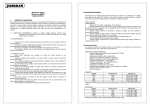
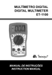
To all residents of the European Union
Important environmental information about this product
This symbol on the device or the package indicates that disposal of the device after its lifecycle could
harm the environment.
Do not dispose of the unit (or batteries) as unsorted municipal waste; it should be taken to a specialised
company for recycling.
This device should be returned to your distributor or to a local recycling service.
Respect the local environmental rules.
If in doubt, contact your local waste disposal authorities.
1. SAFETY
1.1. SAFETY INFORMATION
This multimeter has been designed in accordance with IEC-1010. This norm pertains to
electronic measuring instruments that emit pollution 2 and belong to an overvoltage category
(CAT II).
Follow all safety and operating instructions to ensure that the meter is used safely and is kept
in good running order.
Full compliance with safety standards can only be guaranteed when the buyer uses the test
leads supplied with this packaging. If necessary, they should be replaced with identical leads.
1.2. SAFETY SYMBOLS
Important safety information, refer to the user manual.
Dangerous voltage is possible.
Earthing.
Double insulation (class II-protection)
Replace a blown fuse by a fuse with the same ratings as specified in this
manual.
DVM850BL
1
GB
2. MAINTENANCE
• Before opening the case, always disconnect the test leads from all live circuits.
• Avoiding fire risks : respect the specified voltage and current ratings when replacing the
fuse.
F 200mA / 250V (Quick acting)
• Do not use the device unless the back cover is in place and securely fastened.
• Do not apply abrasives or solvents to the meter. Use a damp cloth and mild detergent for
cleaning purposes.
3. DURING USE
• Never exceed the limit value for protection. This limit value is listed separately in the
specifications for each range of measurement.
• Do not touch unused terminals when the meter is linked to a circuit which is being tested.
• Never use the meter with category II installations when measuring voltages that might
exceed the safety margin of 600V above earth ground.
• Set the range selector at its highest position if the intensity of the charge to be measured is
unknown beforehand.
• Disconnect the test leads from the tested circuit before rotating the range selector in order to
change functions.
• When carrying out measurements on a TV set or switching power circuits, always remember
that the meter may be damaged by any high amplitude voltage pulses at test points.
• Always be careful when working with voltages above 60Vdc or 30Vac rms. Keep your
fingers behind the probe barriers at all times during measurement.
• Before attempting to insert transistors for testing, always verify if the test leads have been
disconnected.
• Components should not be connected to the hFE socket while test leads are being used to
execute voltage measurements.
• Never perform resistance measurements on live circuits.
4. GENERAL DESCRIPTION
The device is a battery-operated, hand-held 3 ½ digital multimeter for measuring DC and AC
voltages, DC current and resistance. It also offers the possibility of executing continuity tests
and of testing diodes and transistors. The back light is optional.
DVM850BL
2
GB
4.1. FRONT PANEL
DVM850BL
3
GB
4.2. FRONT PANEL DESCRIPTION
Display
3 ½ digits, 7 segments, LCD : 15mm high
Back light
When this button is pushed, the back light will illuminate your display for approximately 5
seconds.
Rotary switch
This switch is used to select functions and desired ranges as well as to turn the meter
on/off.
Hold button
Upon pushing this button, the display will retain the last reading and the " "-symbol will
remain on the LCD until the button is pushed again.
"10A" jack
Insert the red test lead in this connector in order to measure a max. current of 10A.
"COM" jack
Insert the black (negative) test lead.
"VΩmA" jack
Insert the red (positive) test lead in this connector to measure voltage, resistance and
current (except 10A).
5. SPECIFICATIONS
Maximum accuracy is achieved during a one-year period after calibration. The ideal set of
circumstances requires a temperature of 18 to 28°C (64°F to 82°F) with a maximum relative
humidity of 80%.
Maximum voltage between terminals and earth ground
Fuse protection
Power
Display
Measuring method
Overrange indication
Polarity indication
Operating temperature
Storage temperature
Low battery indication
Dimensions
Weight
DVM850BL
4
CAT II 600V
F 200mA / 250V
9V battery
LCD, 1999 counts, updates 2-3/sec.
Dual-slope integration A/D converter
Only figure "1" on the display
"-" displayed for negative polarity
0 to 40°C
-10°C to 50°C
"
" appears on the display
138 x 69 x 31mm
Approx. 170g
GB
5.1. DC VOLTAGE
Range
Resolution
Accuracy
200mV
100µV
±0.5% of rdg ± 2 digits
2V
1mV
±0.5% of rdg ± 2 digits
20V
10mV
±0.5% of rdg ± 2 digits
200V
100mV
±0.5% of rdg ± 2 digits
600V
1V
±0.8% of rdg ± 2 digits
Overload protection : 250Vrms for the 200mV range and 600Vdc or rms ac for other ranges.
5.2. DC CURRENT
Range
Resolution
Accuracy
200ùA
0.1µA
±1% of rdg ± 2 digits
2mA
1µA
±1% of rdg ± 2 digits
20mA
10µA
±1% of rdg ± 2 digits
200mA
100µA
±1.5% of rdg ± 2 digits
10A
10mA
±3% of rdg ± 2 digits
Overload protection : F 200mA / 250V fuse. (no fuse for the 10A range).
5.3. AC VOLTAGE
Range
Resolution
Accuracy
200V
100mV
±1.2% of rdg ± 2 digits
600V
1V
±1.2% of rdg ± 2 digits
Overload protection : 600Vdc or rms ac for all ranges.
Frequency range : 40Hz to 400Hz. Response : average, calibration in rms of a sine wave.
5.4. DIODE & CONTINUITY
Range
Description
If continuity exists (less than 60Ω), built-in buzzer will sound
Displays the diode's approx. forward voltage drop
Overload protection : 250Vdc or rms ac
DVM850BL
5
GB
5.5. RESISTANCE
Range
Resolution
200Ω
0.1Ω
2kΩ
1Ω
20kΩ
10Ω
200kΩ
100Ω
2MΩ
1kΩ
Maximum open circuit voltage : 3.2V
Overload protection : 250Vdc or rms ac for all ranges.
Accuracy
±0.8% of rdg ± 2 digits
±0.8% of rdg ± 2 digits
±0.8% of rdg ± 2 digits
±0.8% of rdg ± 2 digits
±1.0% of rdg ± 2 digits
5.6. TRANSISTOR hFE TEST (0-1000)
Range
NPN & PNP
Tested range
0-1000
Tested current
Ib = 10µA
Tested voltage
Vcd = 3V
6. OPERATING INSTRUCTIONS
6.1. DC VOLTAGE MEASUREMENT
1. Connect the red test lead to the "VΩmA" jack and the black lead to the "COM" jack.
2. Set the rotary switch in the desired DCV position. If the voltage to be measured is unknown
beforehand, you should set the range switch in the highest range position and then reduce
gradually until the ideal resolution is obtained.
3. Connect the test leads to the source being measured.
4. Read the voltage value on the LCD display along with the polarity of the red lead
connection.
6.2. DC CURRENT MEASUREMENT
1. Connect the red test lead to the "VΩmA" jack and the black test lead to the "COM" jack
(switch the red lead to the "10A" jack for measurements between 200mA and 10A).
2. Set the rotary switch (DCA) in the desired position.
3. Open the circuit in which the current is to be measured and connect the test leads to the
circuit IN SERIES.
4. Read the current value and the polarity of the red lead connection on the LCD display
DVM850BL
6
GB
6.3. AC VOLTAGE MEASUREMENT
1. Connect the red test lead to the "VΩmA" jack and the black test lead to the "COM" jack.
2. Set the rotary switch in the appropriate ACV position.
3. Connect the test leads to the source to be measured.
4. Read the voltage value on the LCD display.
6.4. RESISTANCE
1. Connect the red test lead to the "VΩmA" jack and the black test lead to the "COM" jack (the
red lead has a positive polarity "+").
2. Set the rotary switch in the appropriate "Ω" range position.
3. Connect the test leads to the resistor to be measured and read the LCD display.
4. If the resistance being measured is connected to a circuit, turn off the power and discharge
all capacitors before applying the test probes.
6.5. DIODE TEST
1. Connect the red test lead to "VΩmA" jack and the black one to the "COM" jack (the red lead
has a positive polarity "+".).
2. Set the rotary switch in the " " position.
3. Connect the red test lead to the anode of the diode to be tested and the black test lead to the
cathode of the diode. The approx. forward voltage drop of the diode will be displayed. If the
connection is reversed, the display will merely show a "1".
6.6. TRANSISTOR TEST
1. Set the rotary switch in the "hFE" position.
2. Determine whether the transistor under testing is NPN or PNP and locate the emitter, base
and collector leads. Insert the leads into the proper holes of the hFE-socket on the front
panel.
3. Read the approximate hFE-value obtained under the following test conditions : a base
current of 10µA and Vce 3V.
DVM850BL
7
GB
6.7. AUDIBLE CONTINUITY TEST
1. Connect the red test lead to "VΩmA" and the black one to "COM".
2. Set the range switch in the " " position.
3. Connect the test leads to two points of the circuit to be tested. If continuity exists, the builtin buzzer will sound.
7. BATTERY & FUSE REPLACEMENT
When"
" is displayed, the battery should be replaced.
Fuses rarely need replacement and blown fuses almost always result from human error.
To replace the battery or fuse (200mA / 250V), simply remove the 2 screws at the back of the
case. Remove the old specimen and insert the new one.
Please remember to observe battery polarity.
8. WARNING
Before attempting to open the case, verify if the test leads have been disconnected. Before
using the meter, please remember to close the case and tighten the screws properly in order to
avoid electroshocks.
9. ACCESSORIES
•
•
•
•
•
User manual
Set of test leads
Gift box
9V battery
Holster
DVM850BL
8
GB