1
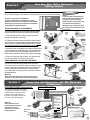
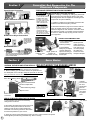
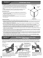
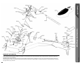
Hummingbird
Elite 3D Pro
Instruction
Manual
SPECIFICATIONS
This Super-Micro R/C helicopter has the most advanced capabilities and is considered topof-the-line. 120 degree eCCPM control, collective main and tail rotors, torque tube tail drive
and brushless motor ensure top performance.
MOTOR SIZE:
MAIN ROTOR DIAMETER:
LENGTH:
WEIGHT:
4100 RPM/Volt
520mm
485mm
360-380g with electronics and battery
Century Helicopter Products
Designed and Developed in USA
Copyright February 2005. All rights reserved.
Century Helicopter Products
1740-C Junction Ave.
San Jose, CA 95112
Fax: (408) 451-1156
Web:www.centuryheli.com
Introduction
Thank You For Choosing The Hummingbird Elite
3D Pro Helicopter From Century!
Required Items
Introduction
Congratulations on the purchase of Century Helicopter Product’s Hummingbird
Elite series helicopter. The Hummingbird Elite is not only ideal for beginners new
to the hobby, but also for the intermediate to expert pilot looking for the ultimate
in micro electric helicopter performance. The 3D Pro requires a 6+ channel
computer radio that supports 120 degree eCCPM operation. Please check with
your favorite retailer or manufacturer to verify compatibility of your radio system of
choice.
Items needed to fly the Hummingbird
1x Radio (6 channels)
1x Receiver (6 channels)
4x Micro servos
1x Micro gyro
1x Brushless motor (4100 RPM/Volt)
1x Brushless speed controller
1x Battery (11.1V Li-Poly or Li-Ion)
1x Charger (Li-Poly or Li-Ion type)
Warning
This radio controlled model is not a toy! It is a precision machine requiring proper assembly and setup to avoid
accidents. It is the responsibility of the owner to operate this product in a safe manner as it can inflict serious injury.
The helicopter is made pre-assembled and will require inspection for construction before your first flight.
As the manufacturer, we assume no liability for the use of this product.
Rules Of R/C
-Always turn your transmitter on before powering the model.
-Always turn off the model by disconnecting the helicopter
battery prior to turning off the transmitter.
-Always start the helicopter with throttle in the low position.
-Always perform a pre-flight inspection for safe operation.
These rules will help prevent unsafe operation.
Table of Contents
Table of Contents & Introduction ......................................... 2
Required Items and Building Guide for Assembly ............. 2
Getting started ...................................................................... 3
Connections for electronics ................................................. 3
Testing the electronics ......................................................... 4
Servo basics .......................................................................... 4
Servo/pushrod Setup ............................................................ 5
Collective Pitch Setup .......................................................... 6
Tail rotor setup ...................................................................... 6
Blade Tracking, Questions and answers Section............... 7
Your first Flight ...................................................................... 8
Exploded view diagram / warranty information ................ 9
Replacement Parts and Options ........................................ 10
When You Master Your Hummingbird!
Hawk Pro
CN1000C Hawk Pro Helicopter Kit
CN1000C1 Hawk Pro w/O.S. 32 Engine
The Ultimate .30 Size Nitro
R/C Helicopter
Coming March 2005!
Learn more at www.centuryheli.com!
The complete solution for serious 3-D
Kings! Upgraded for maximum performance!
CN1000B
Falcon 50 SE Helicopter Kit
engine radio gyro and muffler sold seperately unless indicated otherwise.
2
Learn more at www.centuryheli.com!
Your New Elite 3D Pro Helicopter
Getting Started
Section 1
CHECKING OVER THE MODEL
Ex
tr
as
Extr
tras
Before beginning, check the kit contents. This is a good time to check the “required
items” section on page 2 and make sure everything necessary is on hand for assembly.
Some items that are packaged with
the helicopter are not attached to the
helicopter. This will include main
blades and bolts, antenna tube, tools,
servo tape and some fasteners.
Brushless motor connectors will only
be included if you purchased a 3D Pro
motor combo.
Important: High Performance Machine:
Check your model before assembling. Check all
fasteners and mechanics for tightness and symetry
before flying your. Be sure to inspect the model after
every flight as a safety precaution.
INITIAL MECHANICAL ADJUSTMENTS
The Hummingbird 3D Pro series flybar and main blades
must be set properly after removing from the package.
1
1. Slide the flybar until it is centered in the rotor head
having equal length on each side.
2
Slide
flybar
2. Tighten the two set screws in the flybar control arms to
secure the flybar. Flybar paddles must be parallel to each
other and the ground when the swashplate is level. Make
sure the screw head in each paddle faces upwards.
3. Install the main rotor blades for clockwise rotation (thick
portion of blades are LEADING edge). Use a conservative
amount of pressure when installing the blade bolts. The
blade tension should be medium and equal on both grips.
flybar
paddle
4
2
4. Remove the canopy and set aside. You will not need
the canopy until the end of the setup process.
Leading edge
USING ADHESIVES TO SECURE THE MODEL
Glue
Check over loose non-moving areas of the helicopter.
Secure any loose connections using the adhesive of your
choice. Using CA (cyanocrylite) glue is very effective but
difficult to debond for maintainance. Household white
glue, although not as strong, works well and is easier to
dissasemble later.
Glue
Glue
Warning!
Only use double sided servo tape for mounting your
electronics. Glue will damage servos and electronics.
Section 2
Connection And Diagnostics For The Electronic
Components
ELECTRONIC CONNECTION OVERVIEW
(S)signal, (+)Positive, (-)Negative
See receiver instructions for detail.
This diagram represents the overall
connections for wiring the Hummingbird Elite 3D Pro correctly (if using
Futaba or Hitec). This diagram
includes the separate connections
pictured on the following page.
Warning!
Keep electronics from
becoming exposed to glue,
moisture or extreme
temperatures to ensure
proper operation.
Pitch Servo
(collective
pitch)
s+ -
Gyro
Aileron
Servo
Brushless
Motor
Elevator
Servo
Rudder
Servo
When
connecting
the ‘Century’
gyro the
orange signal
wires must
face each
other. Other
gyros may
vary.
Battery
Brushless
Controller
3
Connection And Diagnostics For The
Electronic Components
Section 3
Speed Control Connection
TESTING AND PREPARATION OF RADIO EQUIPMENT
6 5 4 3 2 1
Channels
Aileron, Elevator & Pitch Servo Connection
654321
Channels
Ch#1
Aileron
Ch#2
Elevator
Ch#6
Pitch (CP)
IMPORTANT:
!
All connections shown
in this manual work for
Futaba & Hitec radio
systems. If you have
any other radio system
please consult your
radio instructions for
channel numbering.
(some equipment may
differ in appearance.)
Positive negative and
signal pins for the
receiver should be
marked on the casing of
the receiver or in the
manual for the receiver.
PLEASE DON’T SKIP THIS SECTION!!!!
Before modifying or installing any radio gear, please take
a few minutes to test everything as shown. Time spent
becoming familiar with the equipment and testing all the
components can prevent difficulty.
1. Install the crystals into the transmitter and receiver. Be
certain that the channel frequency matches.
2. Note that all electronics plug into the receiver with the
wires as pictured (orange wire faces receiver label).
Follow the diagram for each electronic connection. Once
the electronics system is connected and the transmitter
is turned on, follow this step-by-step process to check
your equipment.
Rudder Servo & Gyro Connections
The gyro helps the
helicopter maintain
heading. Without the
gyro the helicopter
might spin out of
control.
123456
Channels
STEP-BY-STEP COMPONENT TEST
1
2
Motor Connection
The blades on the helicopter should spin clockwise. If the
motor is turining the wrong way, switch two of the motor
wires to reverse the rotation.
Channel
Signal, positive &
numbers must
negative are
match
connected correctly
Section 4
1. Turn on the transmitter 3. Move the aileron,
elevator pitch and
- Is the transmitter
rudder channels to
functioning normally?
make sure the servos
work. With the gyro
2. Plug the Battery
connected properly
battery into your Speed
the rudder servo
controller. Wait for the
should move when
speed control and gyro
to initialize befor moving turning the helicopter.
the helicopter.
Servo Basics
AILERON, ELEVATOR AND PITCH SERVOS - (DO
NOT MODIFY THE RUDDER SERVO)
TEST EVERYTHING FIRST!
1 & 2. Trim both servo mounting flanges from each servo.
3. Before installing you will need to remove the pushrods from
the swashplate of the helicopter. Keep the pushrods on the side
until you install the correct servo arms (next subsection).
2
1
Servo Arm Retaining Screw
The Ser
vo
Servo
Carefully
remove ball
link from
swashplate
ball. Too
much force
may break
the plastic
balls.
3
Servo Arm/Horn/Wheel
Servo Output Shaft
Servo Mounting Flange
Servo Case
Servo Lead w/
Connector
IMPORTANT: Do not modify the rudder servo
BAD
GOOD
SERVO ARMS AND HORNS FOR THE 3D PRO
1. A long half arm may have to be created by
cutting a full or cross arm.
2. After testing the radio equipment the servos will
be in their center position. Remove the servo
retaining screw and servo wheel. Replace the
wheel with one of the long half arms. See section
3 for the final positions for your version.
2
1
3. Some servo arms require widening the hole in the arm in order for them to accept the
Hummingbird’s pushrods using a #55 drill bit [1.34mm or 0.052”].
4
3
10-12mm
Servo Installation And Pushrod Setup
For The 3D Pro
Section 5
MOUNTING YOUR SERVOS (USE SECTION 4 FOR DETAILS)
1. Insert the pushrod into the hole on
the servo arm farthest from the output
(10-12mm from center).
1
3
2
2. Place servo tape on the mounting
surface before mounting the servo.
3. Note that the elevator servo is
mounted slightly forward (3mm or so).
This will ensure that the arm can
move freely (avioding contact with the
frame).
4
4. If the servo has a label on the same side
that will mount with servo tape, peel off the
label and clean the surface using rubbing
alcohol. Once the mounting position of the
servo is determined carefully mount the servo
to the mast tower.
6
5
5. After mounting the servo. Place the plastic
ball link on the corresponding control ball on
the swashplate. Only use the large end of the
tapered opening on the ball link.
6. There are 3 servos needed on the 3D Pro.
When mounted they should appear as
pictured.
7. Turn the radio on with all sticks and trims centered. Verify
also that paddles, swashplate & servo horns are parallel to
each other and also 90 degrees to the main shaft when all
sticks are centered.
Adjust the lengths of the pushrods by twisting the ball links
clockwise to shorten. Twist counter-clockwise to increase the
rod length.
8.) The Elite 3D Pro helicopter uses the 120 degree eCCPM
control system. This system will require a computer
helicopter radio that supports 120 degree eCCPM. Refer to
Page 6 for detailed instructions on how to use eCCPM.
Collective
Pitch Servo
Main shaft
Swashplate
Adjustable
pushrod and
ball link
7
Servo horn
Top View
Front
8
Ball Links
IMPORTANT:
Elevator
servo
Aileron
servo
!
Refer to Page 6 for
detailed instructions on
how to use the eCCPM
control system.
The correct side of the ball
link to mount has a larger
opening than the other side
and also has a lip in the
plastic around the opening.
Ball link closed end
Ball link open end with lip
5
Section 6
eCCPM Radio Setup
Expert Tips:
To make the setup go easier on transmitters with 5 or more programmable points
on the pitch curve, assuming that the 5 points correspond to low stick, point 1, point
2, point 3 and high stick. Set points 1,2,3 to 50% which will create a flat pitch curve
in the center that will allow you to consistently find 50% pitch near mid stick. After
servo direction and centering is completed, return points 1 & 3 back to their default
values.
For highly aerobatic flying, when the rotor head speed is at 1500rpm or above,
bond the flybar paddles in place using cyanoacrylate glue to the flybar.
Heli Front/Nose
*see page
5, step 8
Pitch
Aileron
Radio Setup Procedure
1. It is best to choose a new model memory (if available) and use the Reset feature to
remove any previous settings or mixes. Remember this usually also returns the radio
configuration to single servo.
2. Locate and activate the swashplate mixing for 1200 ccpm (most manufacturers
set single servo on channel 6 by default).
3. Return both the aileron and elevator trims and subtrims to center along with any
hover pitch knobs.
Elevator
Heli Rear/Tail
Collective Pitch Setup:
4. Power on the transmitter and the helicopter without the motor connected. Power on the model. Center throttle/collective stick to 50%
and find the correct servo arm that is closest to 900 degrees (slightly up or down is ok).
5. Watch as the collective stick is moved that all three servo arms move in the same direction. Any servo that is moving in the wrong
direction should be corrected using the servo reverse function for that channel. Continue until all three servos work together to
move the swashplate in the same direction.
6. Watch as the collective stick is raised that the swashplate moves upwards. If it moves downwards, go to the ccpm swashplate
menu and change the default setting to be opposite, for example, if Pitch is set to +60 then change to -60 and retest.
7. While looking from the back of the helicopter, check that when the elevator stick is moved forward that the swashplate tips forward
and when the aileron stick is moved left the swashplate tips left. If the swashplate moves in the wrong direction, change the
direction from the same ccpm swashplate menu. Change from the default value of +60 to -60 and retest.
8. Now that the servos are moving in the correct directions, the servo horn must be trimmed using the internal subtrim feature to
position the arm be 90 degrees to its pushrod (and to the length of the servo), use the subtrim (or centering feature) to achieve this
angle, be as precise as possible.
9. Carefully remove the three pushrods from the swashplate and verify the length is 25mm from the “z” bend to the center of the ball
link. Remove each servo horn one at a time and drill the last hole (photo) using a #55 drill bit [1.34mm or 0.052”] that locates the
pushrod at 11-12mm from the center of the servo arm pivot point.
10. Now that the basic radio setup procedure is completed, return to your pitch curve function and restore points 1 & 3 to their default
valves, usually 25% and 75%. Move the collective stick from low to high and watch the swashplate, if the swashplate bends at the
low or high position, reduce the pitch value in the ccpm menu, for example if the value is -60 try -55 and repeat the test. Continue
until the swashplate moves to the limits but does not bend.
11. Move the cyclic (aileron and elevator) sticks to the full horizontal and diagonal positions and see if the swashplate is binding
against the main shaft. If it does, return to the ccpm menu and reduce the value for the servo that is binding. While holding the
cyclic stick in the corner, slowly rotate the rotor head and again watch the swashplate for binding.
Section 7
Tail Setup: Tail Pushrod, Servo And
Blade Grips
When the main shaft turns clockwise the tail rotor should also turn. If the tail does not turn or if it seems to skip, check the gears
inside the tail boom and gearbox. Right rudder input should turn the nose to the right. Left rudder input should turn the nose to the
left. The servo controlling the rudder is mounted on the tail boom just aft of the main mechanics. The Rudder servo mount clamps to
the tail boom and holds the servo in place with two screws. Make sure the grip of the clamp is secure so the mount cannot shift in
any direction.
The Pushrod for tail
changes tail blade pitch
Rudder servo mount
and should be adjusted
with rudder servo
for roughly equal pitch in
installed.
Tail blade
both directions as a
grips
starting point.
Oil Here
6
The servo arm should be positioned for
maximum travel range. setting the servo arm at
a 90 degree angle to the tail boom will give
equal (maximum total) travel distance on both
ends of the servo travel range.
Tail pushrod
The only way to get perfect tail control is to
test your settings and adjust until the
helicopter responds equally for both
directions of rudder control. Keep in mind
that the tail is compensating for main rotor
torque. Note: main rotor torque turns the
helicopter counter-clockwise.
Place a tiny bit of oil (any good
lubricant for metal on metal) on the
tail output shaft. This will keep the
tail pitch slider sliding smoothly on
the output shaft.
Section 8
Tips, Blade Tracking, Q & A
ROUTING THE ANTENNA
To provide the best possible reception for the model, the Hummingbird Elite comes with a plastic tube for routing the antenna. Put a small
hole in one end and pull the antenna all the way through leaving about 2 to 3 inches of slack. Wrap the antenna around the tube. After the
antenna is almost completely wrapped around the plastic tube place a hole at the other end of the tube to secure the end of the antenna.
The Hummingbird Elite series helicopters have brackets in the landing gear for mounting this plastic tube.
Place a hole
here using a
thumb tack.
Place a hole
here using a
thumb tack.
MOUNTING THE BATTERY
The 3D pro is provided with 2 battery mounting standoffs. Place
the battery against the standoffs to test alignment and reinforce
the battery with a small amount of double sided tape or industrial
strength velcro so the battery does not shift.
The battery holders slide back and forth on the lower frame so you
can adjust the center of gravity on the helicopter.
To test your results hold the helicopter by the flybar (flybar should
be 90 degrees from tailboom). Move the battery to have the
helicopter sit level or very slightly nose heavy.
Moving the battery back or forward
will help adjust center of gravity
ADJUSTING THE BLADE TRACKING
Tracking Adjustment
1. Tracking refers to trimming the actual pitch of the main rotor blades to be equal. On the first flight, bring the rotor head up to speed
without leaving the ground and look at the side or profile of the rotor disk (FROM A VERY SAFE DISTANCE, MAKING SURE TO WEAR
EYE PROTECTION).
2. Only one rotor blade should be visible, if there are two distinctive blades then the tracking linkage must be changed. Observe which
blade is tracking above the other by marking one first. Carefully remove the ball link on that blade grip and shorten the link by one
complete turn.
2
1
Very Bad!
GOOD!
TROUBLESHOOTING QUESTIONS AND ANSWERS
Q: Everything is on and connected. Why won’t the rotors turn?
A: -The throttle may not be set in the transmitter or a connection may be loose or diconnected.
-Be sure to follow the guidlines given for the speed controller. Your transmitter or speed controller programming may have to be adjusted for use
with an R/C helicopter.
Q: Why does the helicopter spin like a top?
A: -It’s possible that the rudder channel on your radio is reversed or your gyro is installed improperly.
-You may simply need to adjust a few settings in the transmitter for additional sensitivity.
-Check the connections to the receiver to make sure connections are correct. If the problem persists take a look at the direction the rudder servo
moves when the gyro is activated in relation to the tail rotor pitch.
-Check the pitch control linkage on the tail rotor from endpoint to endpoint making sure the blades have enough pitch and pitch enough in each
direction.
Q: Why is there vibration?
A: -The main blades may be out of track. Refer to the blade tracking information above.
-The main shaft may be bent. This can be difficult to notice when the blades are not moving. A bent main shaft can be caused in a crash or a hard
blade strike.
-Vibration can also result from any loosely connected components such as the battery tray or the landing gear. Make sure to secure them and be
sure to check the frame and flybar every time you crash or have a hard landing as they may need to be repositioned.
Q: Why won’t the helicopter come off of the ground?
A: -Be sure that the gear mesh on the main motor moves smoothly and that the battery is fully charged.
-If you don’t think it’s the battery it’s possible that slightly damaged blades are reducing the possible lift. If there is a part of the blade broken off
especially near the tip the helicopter may not lift properly.
-Check to make sure nothing is rubbing against the main gear possibly slowing its RPM.
-Observe the travel of the collective. Based on varying climates and altitude conditions your endpoind positions may need to be modified to give it
additional pitch. OR:
-You may have too much pitch. Too much pitch will lower your head speed to a point too low to lift the helicopter. Use the throttle and pitch curve
settings in your transmitter to find the best rotor head speed and pitch for at least 3 points on the pitch/throttle.
Q: Why is it so difficult to move the helicopter backwards (or any direction)?
A: -Check all servo movement when the helicopter is in motion and stationary. You are looking for any control input that causes the servo or pushrod in
that area to get caught or bind. After discovering any bind eliminate it by adjusting servo travel or pushrod length. (it is unnecessary to increse the
length of any pushrod or the travel on any servo to a point that may cause binding.)
Q: Why does the helicopter operate on its own without my command inputs?
A: -You may be getting hit with interference. RF interference can occur for many reasons. Ordinary household electronics, televisions, cell phones,
microwaves, electric tools and other R/C models can add to the field of interference affecting your model. Try turning off unnessesary electronics
or find an area where there are less electrical disturbances.
Q: Why does the helicopter still move too far forward or backward even after adjusting the servo arm positions and trims?
A: -The helicopter may not have an even center of gravity. You can slide the battery in it’s mounting tray to adjust it’s center of gravity.
-You can also combine your battery weight centering with trims and servo arm positions to get any desired combination.
-Mount the electronics in the front of the helicopter to avoid being tail heavy. Having the helicopter slightly nose heavy helps improve forward flight
on a helicopter (R/C or otherwise).
7
Section 9
The First Flight
BASIC HOVERING
Hovering
When all is set, ready and checked, it’s time for the initial flight. Try setting aside a 5 foot diameter circle as a takeoff and landing pad.
Keeping the helicopter inside the landing are will help improve your training.
1. Turn the transmitter on first! Turn helicopter on (plugging in the battery) and stand behind the model about 10 feet away.
2. Always watch the nose of the helicopter, move the rudder left and the nose will move left.
3. Start by increasing the throttle slowly until the helicopter rises 1 foot off the ground then set it back down.
4. Repeat this process until you become comfortable with holding the model in the same spot for a few seconds then land it.
After some time at this you can increase the height slightly up to 2-5 ft. (be very carefull not to fly too high) as you are practising taking
off and landing. This is the most basic but required skill for the beginner to learn. Above 2 feet training gear become ineffective.
The many types of hovering
It cannot be stressed enough that mastering the hovering skill is crucial to becoming a good helicopter pilot. As you progress in your
learning, always practise hovering until you are completely comfortable in holding the helicopter in any direction at any altitude.
1. Pilot view - helicopter facing away from you
2. Sideways - Looking at either side of the helicopter left and right
3. Nose in - nose pointing at you
Perfecting hovering enables you to learn all the types and styles of helicopter flying, forward flight, loops and rolls, 3D (aerobatic flying)
and anything you want to do with your helicopter as it can be set up for beginner through to expert. Lastly, have fun!
PRE-FLIGHT CHECKLIST
1. After turning the radio on, move each servo separately looking for unusual or excessive movement.
2. Inspect the main and tail rotor blades for damage. Never fly damaged blades.
3. Inspect the main and tail rotor linkage for play or binding.
4. Turn the main gear in both directions to feel if a problem is developing.
5. Check the electronics connections making sure everything is correct.
TRIM AND THROTTLE ADJUSTMENTS
Control Movement - All trimming of the Hummingbird should be done one click or detent of the subtrims at a time until it will rise
without moving left, right, forward or backward at a location without wind. Some tail rotation is normal at lift off until it is hovering. Start
by lifting the Hummingbird 3-6 inches at a time to practice lift off and landing.
All trim adjustments are to allow you to lift the helicopter
straight up and can be made one click or detent at a time
on the radio.
(1) Collective & Throttle: Slowly raise the throttle stick, the
helicopter should lift off at half stick. If it tends not to lift off
increase the hover pitch on the radio or increase the throttle
trim. If the helicopter lifts off before mid stick decrease these
settings. (collective present in CP model only.)
(2) Rudder: When the helicopter is ready to take off, make a
correction trim first then use the rudder stick to control the Left &
Right. Note, now is a good time to make a final adjustment on
the gyro.
(3) Elevator: If at hover the helicopter tends to move forward,
move the trim down, if it moves backward move the trim upwards
Use the elevator stick to control the Forward & Backward.
(4) Roll (Aileron): If at hover the helicopter tends to move left,
move the trim right, if the helicopter moves to the right move the
trim left. Move the Aileron stick to control the slide of the
helicopter to the Right & Left.
8
Section 10
Construction Diagram
WARRANTY INFORMATION
Your new equipment is warranted to the original purchaser against manufacturer defects in material and workmanship for 30 days from the date of purchase. During this period,
Century Helicopter Products will repair or replace, at our discretion, any component that is found to be factory defective at no cost to the purchaser. This warranty is limited to the
original purchaser and is not transferable.
This warranty does not apply to any unit which has been improperly installed, mishandled, abused, or damaged in a crash, or to any unit which has been repaired or altered by any
unauthorized agencies. Under no circumstances will the buyer be entitled to consequential or incidental damages. This limited warranty gives you specific legal rights. You also have
other rights which may vary from state
9
Section 11
CNE201
Head Axle & Dampeners
Replacement Parts & Upgrades
CNE207
Flybar Paddles
CNE216
Antirotation Bracket
CNE213
CNE250
Auto Rotation Hub & Gear
Main Shaft Bearings
(3x6mm -2pc-)
CNE209A
Swashplate Links
CNE213F
Bottom Plate Flanged
Bearing (Flanged
3x6mm -1pc-)
CNE306
Seesaw Assembly
CNE312
Top Motor Plate
CNE318
Tail Rotor Shaft Assembly
CNE324
Tail Blade Grip Set
with Bearings
CNE301
Motor Mount
CNE307
3D Pro Head links
CNE313
Main Shaft, Spacers & Collar
CNE319
Inner tail Crown Gear
CNE302
3D Pro Main Blade Grips
CNE308
Rear Rudder Servo Mounts
CNE314
3D Pro Swashplate
CNE320
Battery Holders
CNE304
CNE303
Metal Flybar (2)
CNC Rotor Hub & Collar
CNE309
CNE310
Frame Holders
Mast Tower
CNE316
CNE315
Tail Drive Shaft Set
Tail boom, Pushrod & Guides
CNE321
Tail Pitch Lever & Slider
CNE325
CNE326
CNE327
Tail Gear Box Set
Landing Gear Set
Canopy & Decal
Optional Items
10
CNE258
CNE259
CNE327C
Machined Metal Main Rotor
Blade Grips (adjustable)
Machined Metal
Swashplate
Clear Canopy & Decal
CNE361
Brushless Motor Heatsink
CNE322
Tail Rotor Blades
CNE252
Lightning Brushless
Main Motor
CNE305
Tail Drive Shaft Gears
CNE31
1
CNE311
Bottom Frame Plate
CNE317
3D Fins & Boom Supports
CNE323
Main Rotor Blades
PHX-10
Castle Creations Brushless
Speed Control