1
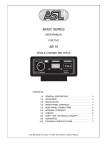
BASIC SERIES
USER MANUAL
FOR THE
BS 181
SINGLE CHANNEL POWER SUPPLY
CONTENTS
1.0
2.0
3.0
4.0
5.0
6.0
7.0
8.0
9.0
10.0
GENERAL DESCRIPTION . . . . . . . . . . . . . . . . . . . . . .
UNPACKING . . . . . . . . . . . . . . . . . . . . . . . . . . . . . . . . .
MECHANICAL INSTALLATION . . . . . . . . . . . . . . . . . . .
MAINS POWER . . . . . . . . . . . . . . . . . . . . . . . . . . . . . . .
FRONT PANEL CONTROLS . . . . . . . . . . . . . . . . . . . . .
REAR PANEL CONNECTORS . . . . . . . . . . . . . . . . . . .
CABLING . . . . . . . . . . . . . . . . . . . . . . . . . . . . . . . . . . . .
PARTY LINE, TECHNICAL CONCEPT . . . . . . . . . . . . .
GUARANTEE . . . . . . . . . . . . . . . . . . . . . . . . . . . . . . . . .
TECHNICAL SPECIFICATIONS . . . . . . . . . . . . . . . . . .
User Manual BS 181 / Issue 1 © 1998 ASL Intercom, Utrecht, Holland.
3
3
3
4
5
5
6
7
7
7
2
User Manual BS 181 / Issue 1 © 1998 ASL Intercom, Utrecht, Holland.
1.0
GENERAL DESCRIPTION
The BS 181 is designed to be a power supply in an ASL
intercom system and can be used in portable as well as
fixed applications.
This makes the BS 181 very versatile and ideal for use in
applications where standard microphone cable is available
and ease of setup is of paramount importance.
The intercom line power supply is fully protected and can
drive at least 20 beltpacks operating at full power.
2.0
UNPACKING
The shipping carton contains the parts listed below.
*
*
*
*
The BS 181
Power cable
Spare fuses
User manual
If any are missing contact your dealer.
With the BS 181 will be a small packet of spare fuses.
Please keep them in a safe place.
ASL has taken great care to ensure that this product
reaches you in flawless condition.
After unpacking the unit please inspect for any physical
damage to the unit, and retain the shipping carton and
relevant packing materials for use should the unit need
returning.
If any damage has occured, please notify your dealer
immediately so that a written claim can be initiated. Please
also refer to the guarantee section of this manual.
3.0
MECHANICAL INSTALLATION
Adequate ventilation must be provided by allowing
sufficient space around the sides and rear of the unit to
ensure free circulation of air. Forced cooling is not
required.
After a period of timethe unit will feel warm to the touch.
This is quite normal, and should be no cause for alarm.
User Manual BS 181 / Issue 1 © 1998 ASL Intercom, Utrecht, Holland.
3
4.0
MAINS POWER
The BS 181 may be connected to the mains power outlet
to which other audio equipment is connected. The outlet
should have a clean earth. Avoid using mains power
outlets which also power dimmer controlled lighting
equipment.
The unit needs no voltage setting and accepts mains
voltages from 90 - 240 V ac, 50/60 Hz.
IMPORTANT
The wires in this mains lead are colour coded in
accordance with the following code:
green and yellow
blue
brown
Earth / safety ground
Neutral
Live
As the colours of the wires in the mains lead may not
correspond with the coloured markings identifying the
terminals in your plug, proceed as follows:
The power cord supplied with this unit carries the following
information label:
-
WARNING
This appliance must be earthed
-
-
The wire which is coloured green-and-yellow must be
connected to the terminal in the plug which is marked
with the letter "E", or by the earth symbol which is
or
coloured green.
The wire which is coloured blue must be connected to
the terminal which is marked with the letter "N" or
coloured black.
The wire which is coloured brown must be connected
to the terminal which is marked with the letter "L" or
coloured red.
Those units that are supplied to the North American
market will have an integral moulded 3 pin connector
which is provided to satisfy required local standards.
4.1
SAFETY EARTHING
The green-and-yellow wire of the mains cord must always
be connected to the electrical installation safety earth or
ground. It is essential for personal safety as well for proper
operation of the BS 181 and the other connected stations.
This wire is internally connected to all exposed metal
surfaces.
4.2
POWERING UP
Powering up procedure:
-
Make sure that the power switch on the left side of the
front panel is OFF.
-
Connect the power cord to the rear of the station.
-
Plug the other end of the power cord into a
PROPERLY GROUNDED outlet.
-
Turn on the power with the red button, the green power
LED will go on, indicating the station is active.
See for further installation and operation the concerning
sections.
4
User Manual BS 181 / Issue 1 © 1998 ASL Intercom, Utrecht, Holland.
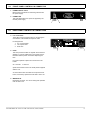
5.0
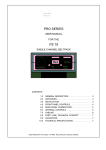
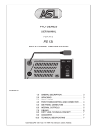
FRONT PANEL CONTROLS & CONNECTOR
1
POWER ON/OFF switch
Mains power push button for switching ON and OFF
the power supply.
2
POWER LED
This LED illuminates if line power is supplied by the
internal power supply.
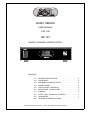
6.0
3
REAR PANEL CONTROLS & CONNECTORS
Line connectors
These XLR-3 type connectors are for connecting the
user-stations, via standard microphone cable.
Pin assignments:
1. 0 V / ground shield
2. +30 V power wire
3. audio wire
4
FUSE
This fuse protects the BS 181 against severe internal
damage, in case of malfunction in the power section.
Disconnected the power cord before replacing the
fuse.
It is most important to place the correct fuse in the
holder :
90 - 240 VAC T 1250 mA
Spare fuses will be found in the small packet supplied
with the unit.
An extra internal fuse is located on the printed circuit
board, if neccesary replace this fuse ONLY with a 4A.
5
MAINS INLET
IEC Mains connector. For correct wiring and operation
refer to section 4.0.
User Manual BS 181 / Issue 1 © 1998 ASL Intercom, Utrecht, Holland.
5
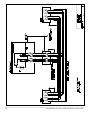
7.0
CABLING
For the BASIC Series Intercom system the interconnecting
cables are of the shielded two-conductor microphone
cable type and the intercom line connectors are of the
XLR-3 type. Audio and Call signals are on XLR pin 3, DC
power is on XLR pin 2. XLR pin 1 is connected to the
shield of the cable which functions as the common return
for audio and power.
¼
Since the audio signal is transferred in an unbalanced
way, certain rules have to be obeyed when installing the
cables of an intercom network. This is to avoid earth loops
and to minimize power loss and the possible effect of
electromagnetic fields.
These rules are:
Use high quality (multipair) cable.
For interconnecting user stations, power supplies and
accessories in an ASL Intercom network, use high
quality shielded two-conductor (minimum 2x 0.30 mm2)
microphone cable only.
In case of a two channel intercom network, use high
quality microphone 'multipair' cable only, each pair
consisting of two conductors (minimum 2x 0.15 mm2)
with separate shield. Multipair cable should also have
an overall shield.
Use flexible cables.
Use flexible single and multipair microphone cable
instead of cable with solid cores, especially when the
cable is subjected to bending during operation or
installation.
Separate cable screen to XLR pin 1.
The screen of each separate microphone cable and/or
the screen of each single pair in a multipair cable,
should be connected to pin 1 of each XLR-3 connector.
Do not connect this cable screen to the metal housing
of the connector or to metal wall boxes (outlets).
See page 10 for Earthing Concept.
Cable trunks, connection boxes and overall
multipair cable screen to clean earth.
Metal cable trunks, metal connection boxes and overall
multipair cable screen should be interconnected and,
at one point (the 'central earthing point') in the intercom
network only, be connected to a clean earth or a safety
earth.
See page 10 for Earthing Concept.
Keep metal connection boxes and cable housings
isolated from other metal parts.
Metal housings for intercom cables and connectors
should be mounted in such a way that they are isolated
from other metal cable and connector housings and
from any other metal construction parts.
Keep cables parallel as much as possible.
When two (two channel) units in a network are
connected by more than one cable, make sure that
these cables are parallel to each other over the whole
distance between those units. When using multipair
cable, parallelism is ensured in the best possible way.
Avoid closed loops.
Always avoid that cables are making a loop. So-called
'ring intercom' should not physically be cabled as a
ring. All cable routes should have a 'star' configuration,
with the central earthing point (usually close to the
power supply position) as the centre of the star.
Keep cables away from electromagnetic sources.
Keep intercom cables away from high energy cables,
e.g. 110/220/380V mains power or dimmer controlled
feeds for spotlights.
Intercom cables should cross high energy cables in at
angle of 90( only.
Intercom cables should never be in the same trunking
as energy cables.
Place power supply in a central position.
In order to avoid unacceptable power losses, place the
power supply as close as possible to where most
power consumption occurs or, in other words, most
user stations are placed.
Connect ASL power supply to a 'clean' mains
outlet.
The ASL power supply may be connected to the mains
power outlet to which other audio equipment is
connected. Avoid using mains outlets which also power
dimmer controlled lighting systems.
In case of more complex installations, don't hesitate to
contact us. Please send us a block diagram of the planned
network with a list of all user stations and their positions,
and we are happy to advise you on cabling lay out.
¼ See Party Line, Technical Concept
6
User Manual BS 181 / Issue 1 © 1998 ASL Intercom, Utrecht, Holland.
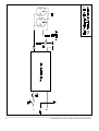
8.0
PARTY LINE, TECHNICAL CONCEPT
ASL's BASIC Series offers a complete two way ('full
duplex') communications system.
Users of the system are connected via a 'party line'.
Master stations (with built-in power supply), beltpacks
and power supplies are interconnected via standard
microphone cable. One wire is used as an audio line,
one as a power line and the screen of the cable functions
as earth/return.
Current drive is used for signal transfer. Each station
utilises a current amplifier to amplify the microphone signal
and place it on the common audio line where, due to the
constant line impedance (situated in the power supply
between XLR pin 3 and 1), a signal voltage is developed
which can be further amplified and sent to the
headphones.
This principle has three advantages:
- the use of a single audio line allows several stations to
talk and listen simultaneously.
- due to the high bridging impedance offered by each
station, the number of stations 'on line' has no
influence on the level of the communications signal.
- power and audio to the intercom stations use the same
cable.
10.0 TECHNICAL SPECIFICATIONS BS 181
POWER SUPPLY
mains voltage range
DC output voltage
ripple and noise
max. output current
all units: 90 -240 V 50/60Hz AC
+30 V +/-5% DC
< 11 mV rms
1,8 A continuous / 2,3 A peak
DIMENSIONS AND WEIGHT
width
height
depth
weight
176 mm
42 mm
139 mm
0.9 Kg
GENERAL SYSTEM SPECIFICATIONS
intercom line impedance
350 ohms (1kHz)
2.2 Kohms (DC)
intercom line audio level
nom. -18 dBu
max. +4 dBu
dynamic range
80 dB
call send signal
2.8 mA
call receive signal threshold
+2.4 V DC
supply voltage
+30 V DC (12 V to 32 V)
Note: 0 dBu = 775 mV into open circuit.
ASL reserves the right to alter specifications without further
notice.
The Call signal is also sent as a current on the audio line.
It develops a DC potential over the line impedance which
will be sensed by each station and interpreted as a Call
signal.
9.0
GUARANTEE
This unit is warranted by ASL Intercom to the original enduser purchaser against defects in workmanship and
materials in it's manufacture for a period of one year from
date of shipment to the end-user.
Faults arising from misuse, unauthorised modifications or
accidents are not covered by this warranty. If the unit is
faulty it should be sent in it's original packing, to the
supplier or your local ASL dealer, with shipping prepaid. A
note must be included stating the faults found and a copy
of the original suppliers invoice.
THIS PRODUCT WAS DESIGNED, DEVELOPED AND
MANUFACTURED BY:
ASL-intercom BV
MAARSSEN (UTRECHT) HOLLAND.
Tel. +31 30 241 1901, Fax +31 30 241 0638
User Manual BS 181 / Issue 1 © 1998 ASL Intercom, Utrecht, Holland.
7
8
User Manual BS 181 / Issue 1 © 1998 ASL Intercom, Utrecht, Holland.
User Manual BS 181 / Issue 1 © 1998 ASL Intercom, Utrecht, Holland.
9
10
User Manual BS 181 / Issue 1 © 1998 ASL Intercom, Utrecht, Holland.
User Manual BS 181 / Issue 1 © 1998 ASL Intercom, Utrecht, Holland.
11