1
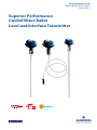
Quick Installation Guide 00825-0100-4530, Rev EC March 2013 Superior Performance Guided Wave Radar Level and Interface Transmitter Quick Installation Guide March 2013 About this guide This installation guide provides basic guidelines for Rosemount 5300 Series transmitters. It does not provide instructions for configuration, diagnostics, maintenance, service, troubleshooting, Explosion-proof, Flameproof, or intrinsically safe (I.S.) installations. Refer to the Rosemount 5300 Series Reference Manual (Document No. 00809-0100-4530) for more instruction. The manual and this Quick Installation Guide (QIG) are also available electronically on www.rosemount.com. Failure to follow safe installation and service guidelines could result in death or serious injury Make sure the transmitter is installed by qualified personnel and in accordance with applicable code of practice. Use the equipment only as specified in this QIG and the Reference Manual. Failure to do so may impair the protection provided by the equipment. Do not perform any services other than those contained in this manual unless you are qualified. Explosions could result in death or serious injury Verify that the operating environment of the transmitter is consistent with the appropriate hazardous locations specifications. See Product Certifications on page 25 in this Quick Installation Guide. To prevent ignition of flammable or combustible atmospheres, disconnect power before servicing. ® Before connecting a HART , FOUNDATION™ fieldbus, or Modbus based communicator in an explosive atmosphere, make sure the instruments in the loop are installed in accordance with intrinsically safe or non-incendive field wiring practices. To avoid process leaks, only use O-rings designed to seal with the corresponding flange adapter. Electrical shock can result in death or serious injury Avoid contact with the leads and terminals. High voltage that may be present on leads can cause electrical shock. Make sure the main power to the Rosemount 5300 Series transmitter is off and the lines to any other external power source are disconnected or not powered while wiring the transmitter. Probes with non-conducting surfaces Probes covered with plastic and/or with plastic discs may generate an ignition-capable level of electrostatic charge under certain extreme conditions. Therefore, when the probe is used in a potentially explosive atmosphere, appropriate measures must be taken to prevent electrostatic discharge. 2 March 2013 Quick Installation Guide Any substitution of non-authorized parts or repair, other than exchanging the complete transmitter head or probe assembly, may jeopardize safety and is prohibited. Unauthorized changes to the product are strictly prohibited as they may unintentionally and unpredictably alter performance and jeopardize safety. Unauthorized changes that interfere with the integrity of the welds or flanges, such as making additional perforations, compromise product integrity and safety. Equipment ratings and certifications are no longer valid on any products that have been damaged or modified without the prior written permission of Emerson Process Management. Any continued use of product that has been damaged or modified without prior written authorization is at the customer's sole risk and expense. Eliminate the risk of ESD discharge prior to dismounting the transmitter head from the probe. Probes may generate an ignition- capable level of electrostatic charge under extreme conditions. During any type of installation or maintenance in a potentially explosive atmosphere the responsible person should make sure that any ESD risks are eliminated before attempting to separate the probe from the transmitter head. Contents Confirm system readiness . . . . . . . . . . . . . . . . . 4 Safety Instrumented Systems (4-20 mA only) 21 Mount the transmitter head/probe . . . . . . . . . 5 Product certifications . . . . . . . . . . . . . . . . . . . . 25 Connect the wiring . . . . . . . . . . . . . . . . . . . . . . . 8 Configure . . . . . . . . . . . . . . . . . . . . . . . . . . . . . . 15 3 March 2013 Quick Installation Guide Step 1: Confirm system readiness Confirm HART revision capability If using HART-based control or asset management systems, confirm the HART capability of those systems prior to transmitter installation. Not all systems are capable of communicating with the HART Revision 7 protocol. This transmitter can be configured for either HART Revision 5 or 7. For instructions on how to change the HART revision of your transmitter, see “Switch HART revision mode” on page 4. Confirm correct Device Driver Verify that the latest Device Driver (DD/DTM) is loaded on your systems to ensure proper communication. Download the latest Device Driver from www.rosemount.com/LevelSoftware. Rosemount 5300 device revisions and drivers Table 1 provides the information necessary to ensure that you have the correct Device Driver and documentation for your device. Table 1. Rosemount 5300 device revisions and files Firmware Version1 2F0 and later 2A2 - 2D2 Find Device Driver HART Universal Revision Device Revision2 7 4 5 3 5 3 Review Instructions Review Functionality Manual Document Number Changes to Software3 00809-0100-4530 Rev EA See footnote 3 for list of changes. 00809-0100-4530 Rev DA N/A 1. Firmware version is printed on the transmitter head label, e.g. SW 2E0. 2. Device revision is printed on the transmitter head label, e.g. HART Dev Rev 4. 3. HART Revision 5 and 7 are selectable. Switch HART revision mode If the HART configuration tool is not capable of communicating with HART Revision 7, the Rosemount 5300 Series will load a Generic Menu with limited capability. The following procedures will switch the HART revision mode from the Generic Menu: 1. Manual Setup > Device Information > Identification > Message To change to HART Revision 5, Enter: “HART5” in the Message field To change to HART Revision 7, Enter: “HART7” in the Message field 4 Quick Installation Guide March 2013 Step 2: Mount the transmitter head/probe Transmitter Housing Tank connection with flange 1. Place a gasket on top of the tank flange. 2. Lower the probe with flange into the tank. Nut Bolt Flange Probe 3. Tighten the bolts and nuts with sufficient torque regarding flange and gasket choice. 4. Loosen the nut that connects the housing to the probe and rotate the housing to the desired direction. Gasket Tank Flange 5. Tighten the nut. Threaded tank connection 1. For adapters with BSP/G threads, place a gasket on top of the tank flange. 2. Lower the probe into the tank. Nut Adapter Probe 3. Mount the adapter into the process connection. Sealant on threads (NPT) or Gasket (BSP/G) 4. Loosen the nut that connects the housing to the probe and rotate the housing to the desired direction. 5. Tighten the nut. Tank Flange/ Process Connection NOTE: For adapters with NPT threads, pressure-tight joints require a sealant. Tri-Clamp tank connection 1. Place a gasket on top of the tank flange. 2. Lower the transmitter and probe into the tank. Nut 3. Fasten the Tri-Clamp to the tank with a clamp. Tri-Clamp Probe Gasket Tank Clamp 4. Loosen the nut that connects the transmitter housing to the probe slightly. 5. Rotate the transmitter housing so the cable entries/display face the desired direction. 6. Tighten the nut. Refer to the Rosemount 5300 Series Reference Manual (Document No. 00809-0100-4530) for details regarding the mounting of transmitter head/probe. 5 March 2013 Quick Installation Guide Step 2 continued... Transmitter housing Bracket mounting, on wall 1. Mount the bracket directly to the wall with screws suitable for the purpose. 2. Mount the transmitter with probe to the bracket and secure the installation with the three supplied screws. Bracket Probe Clamping brackets U-bolts Bracket Transmitter housing Bracket mounting, on pipe 1. Put the two U-bolts through the holes of the bracket. Holes are available for both vertical and horizontal pipe mounting. 2. Put the clamping brackets on the U-bolts and around the pipe. Probe Vertical mounting Transmitter housing Probe Horizontal mounting 6 3. Fasten the bracket to the pipe using the four supplied nuts. 4. Mount the transmitter with probe to the bracket and secure with the three supplied screws. See the Rosemount 5300 Series Reference Manual (Document No. 00809-0100-4530) for more installation details. Quick Installation Guide March 2013 Step 2 continued... Remote housing M50 nut 1. Remove the transmitter head from the probe by unscrewing the M50 nut. For safety information regarding ESD discharge, see the applicable warning on page 3. 2. Mount the probe in the tank. U-bolt Bracket M6 screw Clamping brackets 3. Mount the bracket to the pole, making sure the distance between the probe and bracket does not exceed the length of the remote connection. Put the two U-bolts through the holes of the bracket. Several holes are available for vertical/horizontal pipe mounting. Put the clamping brackets on the U-bolts and around the pipe. Use the supplied nuts to fasten the bracket to the pipe. 4. Fasten the housing support to the bracket using the M6 screws. The screws are threaded through the top of the mounting bracket and into the housing support. M50 nut 5. Mount the probe housing on the probe, making sure that the M50 nut is properly tightened. 6. Connect the transmitter head on the housing support, making sure that the M50 nut is properly tightened. 7 Quick Installation Guide March 2013 Step 3: Connect the wiring Wiring and power supply requirements can be dependent upon the approval certification. As with all FOUNDATION fieldbus requirements, a conditioned power supply and terminating resistors are required for proper operation. It is recommended that shielded twisted pair wiring (18-12 AWG) suitable for the supply voltage be used and, if applicable, approved for use in hazardous areas. For electrical information, such as power supply, see diagrams and drawings for HART, Modbus, and FOUNDATION fieldbus on the following pages. NOTE: Avoid running instrument cable next to power cables in cable trays or near heavy electrical equipment. It is important that the instrument cable shield be: - trimmed close and insulated from touching the transmitter housing - continuously connected throughout the segment - connected to a good earth ground at the power supply end Grounding When wiring the transmitters, the grounding should be completed such that: The loop is grounded at the power supply. When transmitters are installed on metal tanks, ensure there is a metal-to-metal connection between the device and the tank. If the tank is non-metallic, the housing must be grounded to an earth ground that is separate from the power supply. The external ground terminal may be used for this purpose. If the tank is cathodically protected, the housing must be grounded to an earth ground that is outside of the cathodic protection system ground. Use the external terminal for this purpose. When transient protection terminal block is used, the ground wire should be separate from the signal wire. Use the external ground terminal. Make sure grounding is done (including IS ground inside Terminal compartment) according to Hazardous Locations Certifications, national and local electrical codes. The most effective transmitter housing grounding method is a direct connection to earth ground with minimal (< 1 ) impedance. NOTE: Grounding the transmitter housing using the threaded conduit connection may not provide a sufficient ground. The transient protection terminal block will not provide transient protection unless the transmitter housing is properly grounded. Use the above guidelines to ground the transmitter housing. Do not run transient protection ground wire with signal wiring; the ground wire may carry excessive current if a lightning strike occurs. 8 Quick Installation Guide March 2013 To connect the transmitter 1. Verify that the power supply is disconnected. 2. Remove the terminal block cover (see picture below). 3. Pull the cable through the cable gland/conduit. For Explosion-proof / Flameproof installations, only use cable glands or conduit entry devices certified Explosion-proof or Flameproof. Install wiring with a drip loop where the bottom of the loop must be lower than the cable/conduit entry. 4. To connect the wires, see the illustrations on the following pages. 5. Use the enclosed metal plug to seal any unused port. 6. Tighten the cable gland. 7. Mount the cover and make sure it is fully engaged to meet Explosion-proof requirements (adapters are required if M20 glands are used). For ATEX, IECEx, NEPSI, INMETRO, and TIIS installations, lock the cover with the locking screw. 8. Connect the power supply. NOTE: Use PTFE tape or other sealant at the NPT threads in the Cable Entries. Terminal block Terminal Block Cover Terminals for signal and power supply Cable Entry, ½ in. NPT - 14 or M20x1.5 adapter Cable Entry, ½ in. NPT - 14 or M20x1.5 adapter External Ground Screw Internal Ground Screw Locking screw Remove the orange, protective, plastic plugs, used for transportation. Seal any unused port with the enclosed metal plug. 9 March 2013 Quick Installation Guide Step 3 continued... HART communication The Rosemount 5300 Series transmitter operates with a power supply ranging from 16 - 42.4 Vdc (16 - 30 Vdc in IS applications, 20-42.4 Vdc in Explosion-proof / Flameproof applications and in Non-Sparking / Energy Limited applications). All configuration tools for HART communication, such as the Field Communicator and Rosemount Radar Master, require a minimum load resistance (RL) of 250 within the loop in order to function properly, see diagrams below. Non-intrinsically safe power supply PC Power Supply Field Communicator Rosemount 5300 Series Transmitter HART Modem Load Resistance 250 NOTE: Rosemount 5300 Series Transmitters with Flameproof/Explosion-proof output have a built-in barrier; no external barrier needed. Intrinsically safe power supply PC Power Supply HART Modem Field Communicator RL250 Approved IS Barrier For IS Parameters, see the Product certifications chapter. 10 Rosemount 5300 Series Transmitter Quick Installation Guide March 2013 Step 3 continued... Type n approvals : non-sparking / energy limited power supply PC Power Supply Field Communicator Rosemount 5300 Series Transmitter HART Modem Load Resistance 250 HART: Un = 42.4 V Transient protection terminal block PC Power Supply Field Communicator HART Modem Rosemount 5300 Series Transmitter Transient Protection Symbol Load Resistance 250 HART: Un = 42.4 V 11 March 2013 Quick Installation Guide Step 3 continued... Load limitations The Field Communicator requires a minimum load resistance of 250 within the loop to function properly. The maximum load resistance can be obtained from the following diagrams. Non-Hazardous Installations, and Non-Sparking / Energy Limited Power Supply Operating region R(): Maximum Load Resistance UE(V): External Power Supply Voltage Explosion-proof/Flameproof (Ex d) Installations Operating region R(): Maximum Load Resistance UE(V): External Power Supply Voltage Intrinsically Safe Installations R(): Maximum Load Resistance UE(V): External Power Supply Voltage NOTE: For Flameproof / Explosion-proof installations, the diagram is only valid if the HART load resistance is at the + side and if the - side is grounded. Otherwise, the load resistance value is limited to 435 . NOTE: Rosemount 5300 Series Transmitters with Flameproof/Explosion-proof output have a built-in barrier; no external barrier needed. 12 Quick Installation Guide March 2013 Step 3 continued... FOUNDATION fieldbus The Rosemount 5300 Series transmitter, FOUNDATION fieldbus version, operates with a power supply ranging from 9 - 32 Vdc (9 - 30 Vdc in IS applications and 16 32 Vdc in Explosion-proof / Flameproof and in Non-Sparking / Energy Limited applications). FISCO, IS applications: 9 - 17.5 Vdc. Non-intrinsically safe power supply Rosemount 5300 Series Transmitter Power Supply Field Communicator Fieldbus Modem PC NOTE: Rosemount 5300 Series Transmitters with Flameproof/Explosion-proof output have a built-in barrier; no external barrier needed. Intrinsically safe power supply Rosemount 5300 Series Transmitter Approved IS Barrier Power Supply Field Communicator Fieldbus Modem PC For IS Parameters, see the Product certifications chapter. 13 March 2013 Quick Installation Guide Step 3 continued... Type n approvals : non-sparking / energy limited power supply Rosemount 5300 Series Transmitter Power Supply Field Communicator Fieldbus Modem PC RS-485 with Modbus communication The 5300 Series RS-485 with Modbus communication transmitter version operates using a power supply ranging from 8 - 30 Vdc (max. rating). See the Rosemount 5300/5400 Series with HART to Modbus Converter Manual supplement (Document No. 00809-0500-4530) for details. Power Consumption: < 0.5 W (with HART address = 1) < 1.2 W (incl. four HART slaves) 120 nverter If it is the last transmitter on the bus, connect the 120termination resistor. MB MODBUS HART to Modbus Converter (RS-485) MA - MB MA MODBUS (RS-485) HART HART + - - POWER + Ambients > 60 ºC HART Use wirin g rated + formin 90 ºC Power Supply A 120 120 RS-485 Bus B NOTE: Rosemount 5300 Series Transmitters with Flameproof/Explosion-proof output have a built-in barrier; no external barrier needed. 14 March 2013 Quick Installation Guide Step 4: Configure NOTE: If the transmitter is pre-configured at the factory, it is only necessary to proceed with the following steps if you need to verify or change the settings. Basic configuration can easily be done either with Rosemount Radar Master, a Field Communicator, the AMS™ Suite, DeltaV®, or any other DD (Device Description) compatible host system. For advanced configuration features, Rosemount Radar Master is recommended. Rosemount Radar Master Guided Setup includes a Wizard for Basic Configuration and a Device Specific Setup which are sufficient for most cases. Further configuration options are available using the Setup Functions, as described in the Rosemount 5300 Series Reference Manual (Document No. 00809-0100-4530). Configuration with Rosemount Radar Master Guided Setup is described on the following pages and the corresponding Field Communicator fast key sequence and FOUNDATION fieldbus parameters are given. Help is accessed by selecting the Contents option from the Help menu. Help is also available through a Help button in most windows. The configuration instructions in this Quick Installation Guide cover standard installations. For more complicated situations, such as interface applications or for installations that have disturbing objects within the radar beam etc, see the Rosemount 5300 Series Reference Manual (Document No. 00809-0100-4530). Installing the Rosemount Radar Master software To install Rosemount Radar Master: 1. Insert the installation CD into the CD-ROM drive. 2. Follow the instructions. If the installation program does not start automatically, run Setup.exe from the CD. 15 Quick Installation Guide March 2013 Configuration using the Rosemount Radar Master software 1. Start Rosemount Radar Master (Programs > Rosemount > Rosemount Radar Master). 2. Connect to the desired transmitter. Once the transmitter is connected, the Guided Setup window appears automatically. Run Wizard 3. Click the Run Wizard for guided setup button. Follow the instructions for a Basic Configuration and you will be guided through a short transmitter installation procedure. 4. The first window in the Configuration Wizard presents general information such as Device Model (5301 / 5302 / 5303), serial number, Probe Type, Probe Length, communication protocol, and device address. Check that the information complies with the ordering information. Click Next. 5. The General window lets you enter Tag, Message1, Descriptor1, and Date1. This information is not required for operation of the transmitter and can be left out if desired. Handheld HART Communicator: Fast Key Sequence [2, 2, 1]. Click Next and the following window appears (Probe). 6. Verify that the parameters in the Probe window are correct. The parameters 1) Only for HART communication. 16 March 2013 Quick Installation Guide are normally configured at the factory, but can be changed if, for example, the probe is cut in the field, or if disturbing objects in the near zone need to be blocked out (Hold Off Distance/Upper Null Zone (UNZ)). Handheld HART Communicator: Fast Key Sequence [2, 1, 2]. FOUNDATION fieldbus parameters: TRANSDUCER_1100 > PROBE_TYPE TRANSDUCER_1100 > PROBE_LENGTH TRANSDUCER_1100 > GEOM_HOLD_OFF_DIST Click Next and the following window appears (Geometry). 7. Enter Tank Height, the distance from the Upper Reference Point to the Lower Reference Point (which is the tank bottom in the screenshot above), making sure it is as accurate as possible. See Configuration in the Rosemount 5300 Series Reference Manual (Document No. 00809-0100-4530) for details. Set Mounting Type. Set Diameter if Mounting Type is Nozzle or Pipe/Chamber. Set Nozzle Height if Mounting Type is Nozzle. Handheld HART Communicator: Fast Key Sequence [2, 1, 3] FOUNDATION fieldbus parameters: TRANSDUCER_1100 > GEOM_TANK_HEIGHT TRANSDUCER_1100 > MOUNTING_TYPE TRANSDUCER_1100 > PIPE_DIAMETER TRANSDUCER_1100 > NOZZLE_HEIGHT 17 Quick Installation Guide March 2013 Click Next and the following window appears (Tank Environment). 8. In the Environment window, select Measurement Mode. If the surface is moving up or down at rates over 40 mm/s (1.5 in./s), the Rapid Level Changes box should also be selected. Enter the Upper Product Dielectric Constant (icons for help functions are available to the right). For Interface Level with Submerged Probe and Product and Interface measurement modes, it is important that the dielectric constant value is exact. See the Rosemount 5300 Series Reference Manual (Document No. 00809-0100-4530) for details. Handheld HART Communicator: Fast Key Sequence [2, 1, 4] FOUNDATION fieldbus parameters: TRANSDUCER_1100 > MEAS_MODE TRANSDUCER_1100 > PRODUCT_DIELEC_RANGE TRANSDUCER_1100 > UPPER_PRODUCT_DC TRANSDUCER_1100 > ENV_ENVIRONMENT Click Next and the following window appears (Volume). 9. If volume calculation is desired, choose a pre-defined Volume Calculation Method and tank dimensions based on a tank shape that corresponds to the actual tank. Choose Strapping Table if the actual tank does not match any of 18 Quick Installation Guide March 2013 the available pre-defined tank options, or if high volume accuracy is desired. Choose None if volume calculation is not desired. Handheld HART Communicator: Fast Key Sequence [2, 1, 5] FOUNDATION fieldbus parameters: TRANSDUCER_1300 > VOL_VOLUME_CALC_METHOD TRANSDUCER_1300 > VOL_IDEAL_DIAMETER TRANSDUCER_1300 > VOL_IDEAL_LENGTH TRANSDUCER_1300 > VOL_VOLUME_OFFSET Click Next and the following window appears (Analog Output). NOTE: The 4-20 mA range must not include the upper transition zone, the lower transition zone, or the upper null zone. See the Rosemount 5300 Series Reference Manual (Document No. 00809-0100-4530) for details. 10. This step is not applicable for FOUNDATION fieldbus, the parameters are entered in the AI-block instead. Handheld HART Communicator: Fast Key Sequence [2, 1, 6] For HART communication, choose Primary Variable, PV. Specify the analog output range by setting the Upper Range Value (20 mA) and the Lower Range Value (4 mA) to the desired corresponding level values. The Alarm Mode specifies the output state when a measurement error occurs. Choose between the following: High: 21.75 mA (standard) or 22.5 mA (Namur) Low: 3.75 mA (standard) or 3.6 mA (Namur) Freeze: the output current is set to the last valid value at the time when the error occurs. Click Next. 11. Continue with Steps 2 to 5 in the Guided Setup window: Step 2: Device specific setup might advise you to make further configurations. Handheld HART Communicator: Fast Key Sequence [2, 1, 7, 2]. Step 3: Restart the device to make sure all configuration changes are properly activated. Step 4: View live values from the device to verify that the transmitter works correctly. Step 5: Make a complete backup of the device. 19 Quick Installation Guide March 2013 12. The Basic Configuration with the Radar Master Wizard is now finished. Proceed with the Device Specific Setup to see which additional configuration is needed. You may be required to calibrate Vapor Compensation, to set up Probe End Projection, or to perform a Trim Near Zone depending on type of the device, application, and functions available. For further information, see the Rosemount 5300 Series Reference Manual (Document No. 00809-0100-4530). Step 1: Run Wizard Step 2: Device specific setup Step 3: Restart the device Step 4: View live values from the device Step 5: Make a complete backup of the device For Signal Quality Metrics information and further configuration, see the Rosemount 5300 Series Reference Manual (Document No. 00809-0100-4530). Setup - Modbus communication parameters For transmitters with the Modbus option, do the following to configure the communication parameters: 1. In the Setup menu select General. The following window appears. 2. Choose the Communication tab. 3. Click Modbus Setup. 4. Enter the desired Modbus communication settings. 20 Quick Installation Guide March 2013 Safety Instrumented Systems (4-20 mA only) The following section is applicable to the Rosemount 5300 Prior-Use option (Special certification: QS). Additional Safety Instrumented Systems information is available in the Rosemount 5300 Series Reference Manual (Document No. 00809-0100-4530). The manual is available electronically at www.rosemount.com or by contacting an Emerson Process Management representative. To identify a 5300 Prior-Use option transmitter: Verify the QS option code in the model code, on the label affixed to the outside of the transmitter head or Handheld HART Communicator: Fast Key Sequence [1, 7, 8]. Verify that the Prior-Use safety device is ON or Open Rosemount Radar Master, right click on the device, and select Properties. Verify that the Safety Device (QS Option) is present Installation The device should be installed and configured as a level sensing device per manufacturer’s instructions. The materials must be compatible with process conditions and process fluids. No special installation is required in addition to the standard installation practices outlined in this document. Environmental limits are available in the Rosemount 5300 Series Reference Manual (Document No. 00809-0100-4530), Appendix A: Reference Data. The loop must be designed so the terminal voltage does not drop below the minimum input voltage, see values in Table 2, when the transmitter output is 22.5 mA. Table 2. Minimum input voltage (Ui) at different currents Current Hazardous approval 3.60 mA 3.75 mA 21.75 mA 22.50 mA Minimum input voltage (UI) Non-Hazardous Installations and Intrinsically Safe Installations 16 Vdc 16 Vdc 11 Vdc 11 Vdc Explosion-proof / Flameproof Installations 20 Vdc 20 Vdc 15.5 Vdc 15.5 Vdc Configuration Use a HART-compliant master, such as Rosemount Radar Master or a Field Communicator, to communicate with and verify configuration of the Rosemount 5300 Series. A full review of configuration methods is available in the Rosemount 5300 Series Reference Manual (Document No. 00809-0100-4530). NOTE: The Rosemount 5300 Series transmitter is not safety-rated during maintenance work, configuration changes, multidrop, loop test, or other activity that affects the Safety Function. Alternative means should be used to ensure process safety during such activities. 21 March 2013 Quick Installation Guide Damping User adjusted damping affects the transmitter’s ability to respond to process changes. Therefore, the damping values + response time should not exceed the Safety loop requirements. Alarm and saturation levels DCS or safety logic solver should be configured to handle both High alarm and Low alarm. Table 3 identifies the alarm levels available and their operation values.1 Table 3. Alarm levels and operation values Rosemount Alarm Level Normal Operation 3.75 mA1 4 mA 20 mA 3.9 mA low saturation 21.75 mA2 20.8 mA high saturation Namur Alarm Level Normal Operation 3.6 mA1 4 mA 20 mA 3.8 mA low saturation 22.5 mA2 20.5 mA high saturation 1. Transmitter Failure, hardware or software alarm in Low position. 2. Transmitter Failure, hardware or software alarm in High position. It is assumed that the current output signal is fed to a Safety Integrity Level 2 (SIL2) -compliant analog input board of a safety logic solver. For instructions on alarm level settings, see the Rosemount 5300 Series Reference Manual (Document No. 00809-0100-4530), “Analog Output (HART)” section. NOTE: Only the High or Low Alarm Mode can be used for the Safety Function. Do not choose Freeze Current as an error will not be announced in the current loop. Write protection A Rosemount 5300 transmitter can be protected from unintentional configuration changes by a password protected function. It is recommended to use write protection described in the Rosemount 5300 Series Reference Manual (Document No. 00809-0100-4530), “Write Protecting a Transmitter” section. 1) In certain cases, the transmitter does not go into the user defined alarm state. For example, in case of a short circuit, the transmitter goes into High Alarm state even if Low Alarm has been configured. 22 March 2013 Quick Installation Guide Site acceptance After the installation and configuration, proper operation of the transmitter should be verified. A site acceptance test is therefore recommended. The proof test outlined in this section can be used for this. Operation and maintenance The Rosemount 5300 Series Prior-Use option must be tested at regular intervals to confirm that the overfill and empty tank protection function result in the desired system response. The following proof test is recommended. If an error is found in the safety functionality, the measuring system must be switched out of service and the process held in a safe state by means of other measures. Proof test results and corrective actions taken must be documented at www.emersonprocess.com/rosemount/safety. The required proof test intervals depend on the transmitter configuration and process environment. Refer to the reference manual and the Failure Modes, Effects, and Diagnostic Analysis (FMEDA) report for further information. Proof test This test detects approximately 95% of the possible Dangerous Undetected (DU) failures of the transmitter including the sensor element, not detected by the transmitter’s automatic diagnostics. See the Rosemount 5300 Reference Manual (Document No. 00809-0100-4530) for additional details and instructions. Prior to this test, the echo curve should be inspected to ensure that no disturbing echoes affecting the measurement performance are present in the tank. Required tools: Field Communicator and mA meter. 1. Bypass the logic solver or take other appropriate actions to avoid false trip. 2. Disable write protection if the function is enabled. 3. Using Loop Test, enter the mA value representing a high alarm current output. Verify that the analog current reaches that value using the reference meter. This step tests for compliance voltage problems, such as a low loop power supply voltage or increased wiring resistance. NOTE: Use the Handheld HART Communicator: Fast Key Sequence [2, 4, 1, 4] to perform a Loop Test. See the Rosemount 5300 Series Reference Manual (Document No. 00809-0100-4530) for additional information. 4. Using Loop Test, enter the mA value representing a low alarm current output. Verify that the analog current reaches that value using the reference meter. This step tests for possible quiescent current related failures. 5. Perform a two-point calibration check of the transmitter by applying level to two points on the probe within the measuring range1. Verify that the current output corresponds to the level input values using a known reference measurement. This step verifies that the analog output is correct in the operating range and that the Primary Variable is properly configured. 1) For best performance, use the 4 - 20 mA range points as calibration points. 23 Quick Installation Guide March 2013 6. Enable write protection. 7. Restore the loop to full operation. 8. Remove the bypass from the safety logic solver or otherwise restore normal operation. 9. Document the test result for future reference. Inspection Visual inspection It is recommended to inspect the probe for possible build up or clogging. Special tools Not required. Product repair All failures detected by the transmitter diagnostics or by the proof test must be reported. Feedback can be submitted electronically at www.emersonprocess.com/rosemount/safety (Contact Us). The Rosemount 5300 Series is repairable by complete transmitter head replacement. Contact your local Emerson Process Management representative to perform the replacement. Additional information is available in the Rosemount 5300 Series Reference Manual (Document No. 00809-0100-4530). References Specifications The Rosemount 5300 must be operated in accordance with the functional and performance specifications provided in the Rosemount 5300 Series Reference Manual (Document No. 00809-0100-4530), Appendix A: Reference Data. Failure rate data The FMEDA report includes failure rates and common cause Beta factor estimates. The full report is accessible at www.emersonprocess.com/rosemount/safety/PriorUse.htm. Useful lifetime The established failure rates of electrical components apply within the useful lifetime, which should be based on experience. According to IEC 61508-2, 7.4.7.4, note 3, the useful lifetime often lies within a range of 8 to 12 years for transmitters. 24 March 2013 Quick Installation Guide Product certifications EU conformity The EC declaration of conformity can be found on page 33. The most recent revision of the EC declaration of conformity can be found at www.rosemount.com. Safety Instrumented Systems (SIS) The Rosemount 5300 Series has been evaluated by a third party, Exida, against hardware requirements according to IEC 61508. With a FMEDA (Failure Modes, Effects and Diagnostics Analysis) report with a Safe Failure Fraction (SFF) above 90%, 5300 is suitable in SIS according to the Prior Use methodology. For more information, go to: http://emersonprocess.com/rosemount/safety/. To order the certificate of FMEDA data, use option code QS. Hazardous Locations certifications North-American certifications Factory Mutual (FM) approvals Project ID: 3020497 Specific conditions of use: WARNING: Potential Electrostatic Charging Hazard - The enclosure is constructed from plastic. To prevent the risk of electrostatic sparking, the plastic surface should only be cleaned with a damp cloth. WARNING: The apparatus enclosure contains aluminum and is considered to constitute a potential risk of ignition by impact or friction. Care must be taken into account during installation and use to prevent impact or friction. E51 Explosion-proof: Explosion-proof for Class I, Div. 1, Groups B, C, and D; Dust-ignition-proof for Class II/III, Div. 1, Groups E, F, and G; With Intrinsically Safe connections to Class I, II, III, Div. 1, Groups B, C, D, E, F, and G. Temp. Code T4 Ambient temperature limits: -50 °C to +70 °C2. Seal not required. Approval valid for HART, FOUNDATION fieldbus, and Modbus options. 1) Ordering information code for Product Certifications, see the Rosemount 5300 Series Product Data Sheet (Document No. 00813-0100-4530) or the Rosemount 5300 Series Reference Manual (Document No. 00809-0100-4530). 2) +60 °C with FOUNDATION fieldbus or FISCO option. 25 Quick Installation Guide March 2013 I5, IE1 Intrinsically safe and FISCO model: Intrinsically Safe for Class I, II, III, Div. 1, Groups A, B, C, D, E, F, and G, Class I, Zone 0, AEx ia IIC T4 when installed per Control Drawing: 9240 030-936. Non-Incendive Class I, Div. 2, Groups A, B, C, D, F, and G; Suitable for Class II, III, Div. 2, Groups F and G; 4-20 mA/HART model: Ui = 30 Vdc, Ii = 130 mA, Pi = 1.0 W, Ci = 7.26 nF, Li = 0 H. Max. operation: 42.4 V, 25 mA FOUNDATION fieldbus model: Ui = 30 Vdc, Ii = 300 mA, Pi = 1.3 W, Ci = 0 nF, Li = 0 H. Max. operation: 32 V, 25 mA FISCO model: Ui = 17.5 Vdc, Ii = 380 mA, Pi = 5.32 W, Li = Ci = 0. Temp. Code T4 Ambient temperature limits: -50 °C to +70 °C2 Approval valid for HART, FOUNDATION fieldbus, and FISCO options. Canadian Standards Association (CSA) approvals Certificate: 1514653 Product options bearing the Dual Seal marking meets the Dual Seal Requirements of ANSI/ISA12.27.01-2003. Dual seal annunciation The breach of the secondary seal is annunciated via product leakage from the antenna’s vents. The leakage will be visible and/or audible from the transmitter head’s threads. Dual seal maintenance No maintenance required. Verify proper operation by keeping leak path free from ice or contamination. WARNING: The substitution of components may impair intrinsic safety. E61 Explosion-proof with internal intrinsically safe circuits [Exia] Class I, Div. 1, Groups B, C, and D; Class II, Div. 1 and 2, Groups E, F, and G; Class III, Div. 1 Temp Code T4. Ambient temperature limits -50 °C to +70 °C2 Approval valid for HART, FOUNDATION fieldbus, and Modbus options. I6, IF1 Intrinsically Safe Exia: Class I, Div. 1, Groups A, B, C, and D. Temp Code T4. 4-20 mA/HART model: Ui = 30 Vdc, Ii = 130 mA, Pi = 1.0 W, Ci = 7.26 nF, Li = 0 H. FOUNDATION fieldbus model: Ui = 30 Vdc, Ii = 300 mA, Pi = 1.3 W, Ci = 0 nF, Li = 0 H. FISCO model: Ui = 17.5 Vdc, Ii = 380 mA, Pi = 5.32 W, Li = Ci = 0. Installation Drawing: 9240 030-937 Ambient temperature limits -50 °C to +70 °C2. Approval valid for HART, FOUNDATION fieldbus, and FISCO options. 1) Ordering information code for Product Certifications, see the Rosemount 5300 Series Product Data Sheet (Document No. 00813-0100-4530) or the Rosemount 5300 Series Reference Manual (Document No. 00809-0100-4530). 2) +60 °C with FOUNDATION fieldbus or FISCO option. 26 March 2013 Quick Installation Guide European certifications ATEX approvals Special conditions for safe use (X) The intrinsically safe circuits do not withstand the 500 V AC test as specified in IEC 60079-11 clause 6.4.12. Impact and friction hazards need to be considered according to EN 60079-0 clause 8.1.2 when the transmitter and part of antennas exposed to the exterior atmosphere of the tank is made with light metal alloys and of category II 1G EPL Ga. The Ex ia version of model 5300 FISCO field device may be supplied by an [Ex ib] FISCO power supply when the power supply is certified with three separate safety current limiting devices and voltage limitation which meets the requirements for type Ex ia. E11 Flameproof: Nemko 04ATEX1073X II 1/2 G T4 II 1D T79 °C2 Ex ia/db ia IIC T4 Ga/Gb (-40 °C < Ta < +70 °C3) Ex ta IIIC T79 °C2 (-40 °C < Ta < +70 °C3) Um = 250 V Approval valid for HART, FOUNDATION fieldbus, and Modbus options. I1, IA1 Intrinsically safe and FISCO model: Nemko 04ATEX1073X II 1 G T4 or II 1/2 G T4 II 1 D T79 °C2 Ex ia IIC T4 (-50 °C < Ta < +70 °C3) Ex ia/ib IIC T4 Ga/Gb (-50 °C < Ta < +60 °C) Ex ta IIIC T79 °C2 (-50 °C < Ta < +70 °C3) 4-20 mA/HART model: Ui = 30 Vdc, Ii = 130 mA, Pi = 1.0 W, Ci = 7.26 nF, Li = 0 H. FOUNDATION fieldbus model: Ui = 30 Vdc, Ii = 300 mA, Pi = 1.5 W, Ci = 4.95 nF, Li = 0 H. FISCO model: Ui = 17.5 Vdc, Ii = 380 mA, Pi = 5.32 W, Ci = 4.95 nF, Li < 1 μH. Installation Drawing: 9240 030-938 Approval valid for HART, FOUNDATION fieldbus, and FISCO options. N11 Type n: II 3G Ex nAnL IIC T4 Gc (-50 °C < Ta < +70 °C3) II 3G Ex nL IIC T4 Gc (-50 °C < Ta < +70 °C3) Nemko 10ATEX1072 4-20 mA/HART model: Un = 42.4 V FOUNDATION fieldbus model: Un = 32 V Approval valid for HART and FOUNDATION fieldbus options. 1) Ordering information code for Product Certifications, see the Rosemount 5300 Series Product Data Sheet (Document No. 00813-0100-4530) or the Rosemount 5300 Series Reference Manual (Document No. 00809-0100-4530). 2) +69 °C with FOUNDATION fieldbus or FISCO option. 3) +60 °C with FOUNDATION fieldbus or FISCO option. 27 Quick Installation Guide March 2013 Brazilian certifications INMETRO approvals Special conditions for safe use (X) Letter X in the number of the certificate indicates the following special condition(s) for safe use: For models 530xFxxxxxxxxxE1..., 530xFxxxxxxxxxKA..., 530xFxxxxxxxxxKB... or 530xFxxxxxxxxxKC... and when the sensor area requires an EPL Ga, the installation of the transmitter on the process wall must be done in a way that ensures the minimum degree of protection IP67 in the connection, in compliance with regulation ABNT NBR IEC 60529. The intrinsically safe circuit did not withstand the dielectric rigidity tests with 500 Vca as specified in clause 6.4.12 of regulation IEC 60079-11. Probes covered with plastic or plastic discs should have a non-conductive area not exceeding the maximum permitted area for the MC group, which is 4 cm2. Therefore, when an antenna is used in a potentially explosive atmosphere, appropriate measures should be taken by the user to prevent electrostatic discharge. This equipment contains light metals. The equipment must be installed in a way that the risk of impact or friction with other metal surfaces is eliminated. The Ex ia version of the field device of model FISCO 5300 can be provided with a FISCO [Ex ib] power supply when the power supply is certified with three current limiter safety devices separately and with limitation of voltage, complying with the requirements of the Ex ia model. Certificate: NCC 4205/07X Standards: ABNT NBR IEC: 60079-0:2008/2010, 60079-1:2009, 60079-11:2009, 60079-26:2008 IEC 60079-31:2008 E21 Flameproof: 4-20 mA/HART model: Ex d ia IIC T4 Gb/Ga Ex ta IIIC T79 °C -40 °C < Ta < +70 °C Um: 250 V FOUNDATION fieldbus model: Ex d ia IIC T4 Gb/Ga Ex ta IIIC T69 °C -40 °C < Ta < +60 °C Um: 250 V MODBUS model: Ex d ia IIC T4 Gb/Ga Ex ta IIIC T79 °C -40 °C < Ta < +70 °C Um: 250 V 1) Ordering information code for Product Certifications, see the Rosemount 5300 Series Product Data Sheet (Document No. 00813-0100-4530) or the Rosemount 5300 Series Reference Manual (Document No. 00809-0100-4530). 28 March 2013 Quick Installation Guide I21 Intrinsically safe: 4-20 mA/HART model: Ex ia IIC T4 Ga Ex ta IIIC T79 °C -50 °C < Ta < +70 °C Ui: 30 V, Ii: 130 mA, Pi: 1.0 W, Li: 0 μH, Ci: 7.26 nF FOUNDATION fieldbus model: Ex ia IIC T4 Ga Ex ta IIIC T69 °C -50 °C < Ta < +60 °C Ui: 30 V, Ii: 300 mA, Pi: 1.5 W, Li: 0 μH, Ci: 4.95 nF Installation Drawing: 9240030-938 IB1 FISCO model: FISCO Field Device Ex ia IIC T4 Ga Ex ia/ib IIC T4 Ga/Gb Ex ta IIIC T69 °C -50 °C < Ta < +60 °C Ui: 17.5 V, Ii: 380 mA, Pi: 5.32 W, Li: <1 μH, Ci: 4.95 nF Installation Drawing: 9240030-938 Chinese certifications National Supervision and Inspection Center for Explosion Protection and Safety of Instrumentation (NEPSI) approvals Special conditions for safe use (X): Refer to Certificates GYJ 111230X and GYJ 081131X. E31 Flameproof: HART model: Ex d ia IIC T4 (-40 °C < Ta < +70 °C) DIP A20 TA79 °C FOUNDATION fieldbus model: Ex d ia IIC T4 (-40 °C < Ta < +60 °C) DIP A20 TA69 °C Approval valid for HART, FOUNDATION fieldbus, and Modbus options. I31 Intrinsically safe: HART model: Ex ia IIC T4 (-50 °C < Ta < +70 °C) DIP A20 TA79 °C 4-20 mA/HART model: Ui = 30 V, Ii = 130 mA, Pi = 1.0 W, Ci = 7.26 nF, Li 0 μH FOUNDATION fieldbus model: Ex ia IIC T4 (-50 °C < Ta < +60 °C) DIP A20 TA69 °C Ui = 30 V, Ii = 300 mA, Pi = 1.5 W, Ci 4.95nF, Li 0 μH Approval valid for HART and FOUNDATION fieldbus options. 1) Ordering information code for Product Certifications, see the Rosemount 5300 Series Product Data Sheet (Document No. 00813-0100-4530) or the Rosemount 5300 Series Reference Manual (Document No. 00809-0100-4530). 29 Quick Installation Guide March 2013 IC1 FOUNDATION fieldbus FISCO model: Ex ia IIC T4 (-50 °C < Ta< +60 °C) DIP A20 TA69 °C Ui = 17.5 V, Ii = 380 mA, Pi = 5.32 W, Ci4.95 nF, Li 0.1 μH N3 Type n: HART model: Ex nL IIC T4 (-50 °C < Ta < +70 °C) Ui = 30 V, Ii = 130 mA, Pi = 1.0 W, Ci7.26 nF, Li 0 μH FOUNDATION fieldbus model: Ex nL IIC T4 (-50 °C < Ta < +60 °C) Ui = 30 V, Ii = 300 mA, Pi = 1.5 W, Ci4.95 nF, Li 0 μH Japanese certifications Technology Institution of Industrial Safety (TIIS) approval Special conditions for safe use (X): Refer to certificate TC20104 and TC20192. E41 Flameproof: 4-20 mA/HART model: Transmitter: Ex d [ia] IIC T4x -20 ~ +60 °C DC 20 - 42.4 V Um = 250 V Uo = 22.2 V Io = 177.5 mA Po = 0.985 W Probe: Ex Ia IIC T4X FOUNDATION fieldbus model: Transmitter: Ex d [ia] IIC T4X -20 ~ +60 °C DC 16 - 32 V Um = 250 V Uo = 22.2 V Io = 177.5 mA Po = 0.985 W Probe: Ex ia IIC T4X Installation Drawing: 05300-00548. Approval valid for HART and FOUNDATION fieldbus options. 1) Ordering information code for Product Certifications, see the Rosemount 5300 Series Product Data Sheet (Document No. 00813-0100-4530) or the Rosemount 5300 Series Reference Manual (Document No. 00809-0100-4530) 30 March 2013 Quick Installation Guide IECEx certifications IECEx approvals Special conditions for safe use (X) The intrinsically safe circuits do not withstand the 500 V AC test as specified in IEC 60079-11 clause 6.4.12. Impact and friction hazards need to be considered according to EN 60079-0 clause 8.1.2 when the transmitter and part of antennas exposed to the exterior atmosphere of the tank is made with light metal alloys and of category EPL Ga. The Ex ia version of model 5300 FISCO field device may be supplied by an [Ex ib] FISCO power supply when the power supply is certified with three separate safety current limiting devices and voltage limitation which meets the requirements for type Ex ia. E71 Flameproof: IECEx NEM 06.0001X Ex ia/db ia IIC T4 Ga/Gb (-40 °C < Ta < +70 °C2) Ex ta IIIC T 79 °C3 (-40 °C < Ta < +70 °C2) Um = 250 V. Approval valid for HART, FOUNDATION fieldbus, and Modbus options. I7, IG1 Intrinsically safe and FISCO model: IECEx NEM 06.0001X Ex ia IIC T4 (-50 °C < Ta < +70 °C2). Ex ia/ib IIC T4 Ga/Gb (-50 °C < Ta < +60 °C). Ex ta IIIC T 79 °C3 (-50 °C < Ta < +70 °C2). 4-20 mA/HART model: Ui = 30 Vdc, Ii = 130 mA, Pi = 1.0 W, Ci = 7.26 nF, Li = 0 H. FOUNDATION fieldbus model: Ui = 30 Vdc, Ii = 300 mA, Pi = 1.5 W, Ci = 4.95 nF, Li = 0 H. FISCO model: Ui = 17.5 Vdc, Ii = 380 mA, Pi = 5.32 W, Ci = 4.95 nF, Li < 1 μH. Installation Drawing: 9240 030-938 Approval valid for HART, FOUNDATION fieldbus, and FISCO options. N71 Type n: Ex nAnL IIC T4 (-50 °C < Ta < +70 °C2) Ex n IIC T4 (-50 °C < Ta < +70 °C2) IECEx NEM 10.0005 4-20 mA/HART model: Un = 42.4 V FOUNDATION fieldbus model: Un = 32 V Approval valid for HART and FOUNDATION fieldbus options. 1) Ordering information code for Product Certifications, see the Rosemount 5300 Series Product Data Sheet (Document No. 00813-0100-4530) or the Rosemount 5300 Series Reference Manual (Document No. 00809-0100-4530). 2) +60 °C with FOUNDATION fieldbus or FISCO option. 3) +69 °C with FOUNDATION fieldbus or FISCO option. 31 Quick Installation Guide March 2013 Other certifications Overfill protection Cert. no: Z-65.16-476 U1 TÜV-tested and approved by DIBt for overfill protection according to the German WHG regulations Approval valid for HART and FOUNDATION fieldbus options. Suitability for intended use Compliant with NAMUR NE 95, version 07.07.2006 “Basic Principles of Homologation” For detailed information on product certificates, refer to the Rosemount 5300 Series Reference Manual (Document No. 00809-0100-4530). 32 March 2013 Quick Installation Guide EC Declaration of Conformity Figure 1. EC Declaration of Conformity - page 1 33 Quick Installation Guide Figure 2. EC Declaration of Conformity - page 2 34 March 2013 March 2013 Quick Installation Guide Figure 3. EC Declaration of Conformity - page 3 35 00825-0100-4530 Quick Installation Guide 00825-0100-4530, Rev EC March 2013 Emerson Process Management Rosemount Measurement 8200 Market Boulevard Chanhassen, MN 55317 USA Tel (USA) 1 800 999 9307 Tel (International) +1 952 906 8888 Fax +1 952 906 8889 Emerson Process Management Asia Pacific Pte Ltd 1 Pandan Crescent Singapore 128461 Tel +65 6777 8211 Fax +65 6777 0947 Service Support Hotline: +65 6770 8711 E-mail: [email protected] Emerson Process Management Blegistrasse 23 P.O. Box 1046 CH 6341 Baar Switzerland Tel +41 (0) 41 768 6111 Fax +41 (0) 41 768 6300 Emerson FZE P.O. Box 17033 Jebel Ali Free Zone Dubai UAE Tel +971 4 811 8100 Fax +971 4 886 5465 Emerson Process Management Latin America 1300 Concord Terrace, Suite 400 Sunrise Florida 33323 USA Tel +1 954 846 5030 Emerson Beijing Instrument Co No.6 North Street, Hepingli Dongcheng District, Beijing 100013 China Tel +8610 64282233 Fax +8610 642 87640 © 2013 Rosemount Inc. All rights reserved. All marks property of owner. The Emerson logo is a trade mark and service mark of Emerson Electric Co. Rosemount and the Rosemount logotype are registered trademarks of Rosemount Inc.