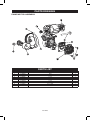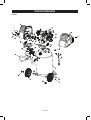
1
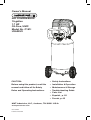
Owner’s Manual AIRCOMPRESSOR 15-gallon 1.7HP Oil-Free,UMC ModelNo.C151I U3A2251I CAUTION: • SafetyInstructions Before using this product, read this manual and follow all its Safety Rules and Operating Instructions. • Installation&Operation • Maintenance&Storage • TroubleshootingGuide • PartsList • Español,p.22 • French,p.45 MAT Industries, LLC, Jackson, TN 38301 U.S.A. www.powermate.com 07/21/2014 Part No. E107724 TABLEOFCONTENTS Page Warranty . . . . . . . . . . . . . . . . . . . . . . . . . . . . . . . . . . . . . . . . . . . . . . . . . . . . . . . . see below Safety Symbols . . . . . . . . . . . . . . . . . . . . . . . . . . . . . . . . . . . . . . . . . . . . . . . . . . . . . . . . . . .3 Important Safety Instructions & Guidelines . . . . . . . . . . . . . . . . . . . . . . . . . . . . . . . . . . . . . .3 Hazard . . . . . . . . . . . . . . . . . . . . . . . . . . . . . . . . . . . . . . . . . . . . . . . . . . . . . . . . . . . . . . . . 4-9 Specifications . . . . . . . . . . . . . . . . . . . . . . . . . . . . . . . . . . . . . . . . . . . . . . . . . . . . . . . . . . . .9 Glossary . . . . . . . . . . . . . . . . . . . . . . . . . . . . . . . . . . . . . . . . . . . . . . . . . . . . . . . . . . . . . . . .9 Duty Cycle . . . . . . . . . . . . . . . . . . . . . . . . . . . . . . . . . . . . . . . . . . . . . . . . . . . . . . . . . . . . . .10 Overview . . . . . . . . . . . . . . . . . . . . . . . . . . . . . . . . . . . . . . . . . . . . . . . . . . . . . . . . . . . . . . .11 Assembly . . . . . . . . . . . . . . . . . . . . . . . . . . . . . . . . . . . . . . . . . . . . . . . . . . . . . . . . . . . . . . .12 Installation . . . . . . . . . . . . . . . . . . . . . . . . . . . . . . . . . . . . . . . . . . . . . . . . . . . . . . . . . . . 13-14 Operating Procedures . . . . . . . . . . . . . . . . . . . . . . . . . . . . . . . . . . . . . . . . . . . . . . . . . . . . .15 Maintenance . . . . . . . . . . . . . . . . . . . . . . . . . . . . . . . . . . . . . . . . . . . . . . . . . . . . . . . . . . . .16 Storage . . . . . . . . . . . . . . . . . . . . . . . . . . . . . . . . . . . . . . . . . . . . . . . . . . . . . . . . . . . . . . . .16 Troubleshooting Guide . . . . . . . . . . . . . . . . . . . . . . . . . . . . . . . . . . . . . . . . . . . . . . . . . 17-18 Parts List . . . . . . . . . . . . . . . . . . . . . . . . . . . . . . . . . . . . . . . . . . . . . . . . . . . . . . . . . . . 19-21 Spanish . . . . . . . . . . . . . . . . . . . . . . . . . . . . . . . . . . . . . . . . . . . . . . . . . . . . . . . . . . . . . . . 22 French . . . . . . . . . . . . . . . . . . . . . . . . . . . . . . . . . . . . . . . . . . . . . . . . . . . . . . . . . . . . . . . . 45 TwOyEARLIMITEdwARRANTy whatdoesThiswarrantyCover?MAT Industries, LLC. (the Company) warrants from the date of purchase by the original retail purchaser only, parts and labor to remedy substantial defects found in materials, or workmanship. HowLongdoesTheCoverageLast?The duration of this warranty is Two Years. This warranty is not transferable to subsequent owners. whatMATIndustrieswilldo:MAT Industries, LLC will cover parts and labor to remedy substantial defects due to materials and workmanship during the first year of ownership, with the exceptions noted below, and parts only, to remedy substantial defects due to material and workmanship for the remaining term of coverage with the exceptions noted below. Parts used in repair of whole goods or accessories are warranted for the balance of the original warranty period. whatisNotCoveredUnderThiswarranty? Failure by the original retail purchaser to install, maintain, and operate said equipment in accordance with standard industry practices. Modifications to the product, or tampering with components, or failure to comply with the specific recommendations of the Company set forth in the owner’s manual, will render this warranty null and void. The Company shall not be liable for any repairs, replacements, or adjustments to the equipment, or any costs for labor performed by the purchaser without the Company’s prior written approval. The effects of corrosion, erosion, surrounding environmental conditions, cosmetic defects, and routine maintenance items, are specifically excluded from this warranty. Routine maintenance items such as: oil, lubricants, and air filters, as well as changing oil, air filters, belt tensioning, etc… fall under the owner’s responsibility. Additional exclusions include: freight damage, failures resulting from neglect, accident, or abuse, induction motors when operated from a generator, oil leaks, air leaks, oil consumption, leaky fittings, hoses, petcocks, bleeder tubes, and transfer tubes. • If the compressor is used for commercial, industrial, or military applications, the warranty will apply for 90 days from the date of purchase. Two stage compressors are not limited to a 90 day warranty when used in commercial or industrial applications. • Rentalapplicationsrenderthiswarrantynullandvoid. • Thefollowingcomponentsareconsiderednormalwearitemsandarenotcoveredafterthefirstyearofownership:Belts,sheaves, flywheels, check valves, pressure switches, air unloaders, throttle controls, electric motors, brushes, regulators, o-rings, pressure gauges, tubing, piping, fittings, fasteners, wheels, quick couplers, gaskets, seals, air filter housings, piston rings, connecting rods, and piston seals. • Labor,servicecalls,andtravelcharges,arenotcoveredafterthefirstyearofownershiponstationarycompressors(compressorswithout handles, or wheels). Repairs requiring overtime, weekend rates, or any other charges beyond the standard shop labor rate are not covered. • Timerequiredfororientationtrainingfortheservicecentertogainaccesstotheproduct,oradditionaltimeduetoinadequateegress. • Damagecausedbyincorrectvoltage,improperlywired,orfailuretohaveacertifiedlicensedelectricianinstallthecompressor,willrender this warranty null and void. • Damagecausedfrominadequatefiltermaintenance. • Pumpwearorvalvedamagecausedbyusingoilnotspecified. • Pumpwearordamagecausedbyanyoilcontamination. • Pumpwearorvalvedamagecausedbyfailuretofollowpropermaintenanceguidelines. • Operationbelowproperoilleveloroperationwithoutoil. • GasEngines,ifproductisequippedwithagasengine,seeenginemanualforspecificenginemanufacturer’swarrantycoverage. Partspurchasedseparately:The warranty for parts purchased separately such as: pumps, motors, etc., are as follows: FromdateofPurchase • Allsingle&twostagepumps 1year • Electricmotors 90days • Universalmotor/pump 30days • Allotherparts 30days • Noreturnauthorizationwillbeissuedforelectricalcomponentsonceitemsareinstalled. How do You Get Service? In order to be eligible for service under this warranty you must be the original retail purchaser, and provide proof of purchase from one of MAT Industries dealers, distributors, or retail outlet stores. Portable compressors or components must be delivered, or shipped, to the nearest Authorized MAT Industries Service Center. All associated freight costs and travel charges must be borne by the consumer. Please call our toll free number 1-888-895-4549 for assistance. THISwARRANTyGIVESyOUSPECIFICLEGALRIGHTS,ANdyOUMAyALSOHAVEOTHERRIGHTSwHICHVARyFROMSTATE TOSTATE.THECOMPANyMAKESNOOTHERwARRANTyORREPRESENTATIONOFANyKINdwHATSOEVER, EXPRESSEdOR IMPLIEd,EXCEPTTHATOFTITLE.ALLIMPLIEdwARRANTIES,INCLUdINGANywARRANTyOFMERCHANTABILITyANdFITNESS FORPARTICULARPURPOSEAREHEREBydISCLAIMEd.LIABILITyFORCONSEQUENTIALANdINCIdENTALdAMAGESUNdER ANyANdALLwARRANTIES,OTHERCONTRACTS,NEGLEGENCE,OROTHERTORTSISEXCLUdEdTOTHEEXTENTEXCLUSIONIS PERMITTEdByLAw. MAT Industries, LLC, Jackson, TN 38301 U.S.A. 2- ENG GENERALSAFETyRULES This manual contains information that is important for you to know and understand. This information relates to protecting YOUR SAFETY and PREVENTING EQUIPMENT PROBLEMS. To help you recognize this information, we use the symbols below. Please read the manual and pay attention to these symbols. Indicates a potentially Indicates an imminently hazardous situation which, if not hazardous situation which, if not avoided, will result in death or serious avoided, may result in minor or moderate injury. injury. Indicates a practice Indicates a potentially not related to personal injury which, hazardous situation which, if not if not avoided, may result in property avoided, could result in death or damage. serious injury. IMPORTANTSAFETyINSTRUCTIONS This product contains chemicals known to the State of California to cause cancer, and birth defects or other reproductive harm. Wash hands after handling. Some dust contains chemicals known to the State of California to cause cancer, birth defects or other reproductive harm such as asbestos and lead in lead based paint. To reduce the risk of injury, read the instruction manual. SAVETHESEINSTRUCTIONS CALIFORNIA PROPOSITION 65 wARNING: This product contains chemicals known to the State of California to cause cancer, birth defects and/or reproductive harm. HAZARd RISKOFEXPLOSIONORFIRE wHATCANHAPPEN HOwTOPREVENTIT • Alwaysoperatethecompressor • Itisnormalforelectrical contacts within the motor and in a well ventilated area free pressure switch to spark. of combustible materials, gasoline, or solvent vapors. • Ifelectricalsparksfrom compressor come into contact with flammable vapors, they may ignite, causing fire or explosion. • Ifsprayingflammablematerials, locate compressor at least 20' (6.1 m) away from spray area. An additional length of air hose may be required. • Storeflammablematerials in a secure location away from compressor. 3- ENG • Restrictinganyofthecompressor ventilation openings will cause serious overheating and could cause fire. • Unattendedoperationofthisproduct could result in personal injury or property damage. To reduce the risk of fire, do not allow the compressor to operate unattended. • Neverplaceobjectsagainst or on top of compressor. • Operatecompressorinanopen area at least 12" (30.5 cm) away from any wall or obstruction that would restrict the flow of fresh air to the ventilation openings. • Operatecompressorina clean, dry well ventilated area. Do not operate unit in any confined area. Store indoors. • Alwaysremaininattendancewith the product when it is operating. • Alwaysturnoffandunplug unit when not in use. HAZARd RISKTOBREATHING(ASPHyXIATION) wHATCANHAPPEN HOwTOPREVENTIT • Neveruseairobtaineddirectly • Thecompressedairdirectlyfrom from the compressor to supply your compressor is not safe for air for human consumption. The breathing. The air stream may compressor is not equipped with contain carbon monoxide, toxic suitable filters and in-line safety vapors, or solid particles from the air equipment for human consumption. tank.Breathingthesecontaminants can cause serious injury or death. • Workinanareawithgoodcross • Exposuretochemicalsindust ventilation. Read and follow created by power sanding, the safety instructions provided sawing, grinding, drilling, on the label or safety data and other construction sheets for the materials you are activities may be harmful. spraying. Always use certified • Sprayedmaterialssuchaspaint, safety equipment: NIOSH/OSHA paint solvents, paint remover, respiratory protection or properly insecticides, weed killers, may fitting face mask designed for use contain harmful vapors and poisons. with your specific application. 4- ENG HAZARd RISKOFBURSTING Air Tank: OnFebruary26,2002,theU.S.ConsumerProductSafetyCommission published Release # 02-108 concerning air compressor tank safety: Air compressor receiver tanks do not have an infinite life. Tank life is dependent upon several factors, some of which include operating conditions, ambient conditions, proper installations, field modifications, and the level of maintenance. The exact effect of these factors on air receiver life is difficult to predict. If proper maintenance procedures are not followed, internal corrosion to the inner wall of the air receiver tank can cause the air tank to unexpectedly rupture allowing pressurized air to suddenly and forcefully escape, posing risk of injury to consumers. The following conditions could lead to a weakening of the air tank, and result in a violent air tank explosion: wHATCANHAPPEN HOwTOPREVENTIT • Failuretoproperlydraincondensed • Drainairtankdailyoraftereachuse. water from air tank, causing rust If air tank develops a leak, replace and thinning of the steel air tank. it immediately with a new air tank or replace the entire compressor. • Modificationsorattempted repairs to the air tank. • Neverdrillinto,weld,ormakeany modifications to the air tank or its attachments. Never attempt to repair a damaged or leaking air tank. Replace with a new air tank. • Unauthorizedmodifications to the safety valve or any other components which control air tank pressure. • Theairtankisdesignedtowithstand specific operating pressures. Never make adjustments or parts substitutions to alter the factory set operating pressures. Attachments&accessories: • Exceedingthepressurerating of air tools, spray guns, air operated accessories, tires, and other inflatables can cause them to explode or fly apart, and could result in serious injury. • Followtheequipmentmanufacturers recommendation and never exceed the maximum allowable pressure rating of attachments. Never use compressor to inflate small low pressure objects such as children’s toys, footballs, basketballs, etc. 5- ENG HAZARd RISKOFELECTRICALSHOCK wHATCANHAPPEN HOwTOPREVENTIT • Yourcompressorispoweredby • Neveroperatethecompressor electricity. Like any other electrically outdoors when it is raining powered device, if it is not used or in wet conditions. properly it may cause electric shock. • Neveroperatecompressor with protective covers removed or damaged. • Repairsattemptedbyunqualified • Anyelectricalwiringorrepairs personnel can result in serious required on this product should be injury or death by electrocution. performed by authorized service center personnel in accordance with national and local electrical codes. • Makecertainthattheelectrical • ElectricalGrounding:Failure to circuit to which the compressor provide adequate grounding to this is connected provides proper product could result in serious injury electrical grounding, correct voltage or death from electrocution. Refer to and adequate fuse protection. GroundingInstructionsparagraph in the Installation section. HAZARd RISKFROMFLyINGOBjECTS wHATCANHAPPEN HOwTOPREVENTIT • Alwayswearcertifiedsafety • Thecompressedairstreamcan equipment: ANSI Z87.1 eye cause soft tissue damage to protection (CAN/CSA Z94.3) exposed skin and can propel dirt, with side shields when chips, loose particles, and small using the compressor. objects at high speed, resulting in property damage or personal injury. • Neverpointanynozzleorsprayer toward any part of the body or at other people or animals. • Alwaysturnthecompressor off and bleed pressure from the air hose and air tank before attempting maintenance, attaching tools or accessories. 6- ENG HAZARd RISKOFHOTSURFACES wHATCANHAPPEN HOwTOPREVENTIT • Touchingexposedmetalsuch • Nevertouchanyexposedmetal as the compressor head, engine parts on compressor during or head, engine exhaust or outlet immediately after operation. tubes, can result in serious burns. Compressor will remain hot for several minutes after operation. • Donotreacharoundprotective shrouds or attempt maintenance until unit has been allowed to cool. HAZARd RISKFROMMOVINGPARTS wHATCANHAPPEN HOwTOPREVENTIT • Movingpartssuchasthepulley, • Neveroperatethecompressor flywheel, and belt can cause with guards or covers which serious injury if they come into are damaged or removed. contact with you or your clothing. • Keepyourhair,clothing,and gloves away from moving parts. Loose clothes, jewelry, or long hair can be caught in moving parts. • Airventsmaycovermovingparts and should be avoided as well. • Attemptingtooperatecompressor • Anyrepairsrequiredonthisproduct should be performed by authorized with damaged or missing parts or service center personnel. attempting to repair compressor with protective shrouds removed can expose you to moving parts and can result in serious injury. 7- ENG HAZARd RISKOFUNSAFEOPERATION wHATCANHAPPEN HOwTOPREVENTIT • Unsafeoperationofyour • Reviewandunderstandall compressor could lead to serious instructions and warnings injury or death to you or others. in this manual. • Becomefamiliarwiththeoperation and controls of the air compressor. • Keepoperatingareaclearofall persons, pets, and obstacles. • Keepchildrenawayfromthe air compressor at all times. • Donotoperatetheproduct when fatigued or under the influence of alcohol or drugs. Stay alert at all times. • Neverdefeatthesafetyfea tures of this product. • Equipareaofoperation with a fire extinguisher. • Donotoperatemachine with missing, broken, or unauthorized parts. HAZARd RISKOFFALLING wHATCANHAPPEN • Aportablecompressorcanfall • from a table, workbench, or roof causing damage to the compressor and could result in serious injury or death to the operator. 8- ENG HOwTOPREVENTIT Alwaysoperatecompressorina stable secure position to prevent accidental movement of the unit. Never operate compressor on a rooforotherelevatedposition.Use additional air hose to reach high locations. HAZARd RISKOFINjURyFROMLIFTING wHATCANHAPPEN • Seriousinjurycanresult from attempting to lift too heavy an object. HOwTOPREVENTIT • Thecompressoristooheavytobe lifted by one person. Obtain assistance from others before lifting. RISKFROMNOISE wHATCANHAPPEN HOwTOPREVENTIT • Undersomeconditionsandduration • Alwayswearcertifiedsafety of use, noise from this product equipment: ANSI S12.6 may contribute to hearing loss. (S3.19) hearing protection. SAVETHESEINSTRUCTIONS FORFUTUREUSE SPECIFICATIONCHART Model No. Running Horsepower Bore Stroke Voltage Hz-Single Phase MinimumBranchCircuitRequirement Fuse Type Air Tank Capacity (Gallon) Maximum Air Pressure Approximate Cut-in Pressure Approximate Cut-out Pressure SCFM @ 40 PSI SCFM @ 90 PSI C151I 1.7 * 2.875"(73.025mm) 1.45" (36.83 mm) 120 60 15amps Time Delay 15 (56.8 liters) 225 PSI 175 PSIG 225 PSIG 6.8 * 5.1 * * Tested per ISO 1217 Refer to Glossary for abbreviations. GLOSSARy AirFilter Porous element contained within a metal or plastic housing attached to the compressor cylinder head which removes impurities from the intake air of the compressor. Air Tank Cylindrical component which contains the compressed air. CheckValve Device that prevents compressed air from flowing back from the air tank to the compressor pump. Cut-InPressure The low pressure at which the motor will automatically restart. Cut-OffPressure The high pressure at which the motor will automatically shut off. ElectricMotor Device which provides the rotational force necessary to operate the compressor pump. 9- ENG NPT(NationalPipeThread) A seal thread tape must be used to provide a leak-free seal on pipe threaded connections. Pump Produces the compressed air with a reciprocating piston contained within the cylinder. PressureRegulatorKnob Regulates the outgoing pressure from the air outlet to the tool. It is possible to increase or decrease the pressure at the outlet by adjusting this control knob. RegulatorPressureGauge Displays the current line pressure. Line pressure is adjusted by rotating the pressure regulator knob. PressureSwitch Automatically controls the on/off cycling of the compressor. It stops the compressor when the cut-off pressure in the tank is reached and starts the compressor when the air pressure drops below the cut-in pressure.The pressure switch will not automatically start and control the compressor unless the manualAUTO/OffSwitchisinthe AUTOposition. PSI(PoundsPerSquareInch) Measurement of the pressure exerted by the force of the air. The actual PSI is measured by a pressure gauge on the compressor. PressureReliefValve Prevents air pressure in the air tank from rising over a predetermined limit. SCFM(StandardCubicFeetPerMinute) A unit of measure of air delivery. TankPressureGauge Indicates the pressure in the air tank. ThermalOverloadSwitch Automatically shuts off the compressor if the temperature of the electric motor exceeds a predetermined limit. dUTyCyCLE This air compressor pump is capable of running continuously. However, to prolong the life of your air compressor, it is recommended that a 50%-75% average duty cycle be maintained; that is, the air compressor pump should not run more than 3045 minutes in any given hour. ACCESSORIES Accessories for this unit are available at the store the unit was purchased. The use of any other accessory not recommended for use with this tool could behazardous.Useonlyaccessoriesratedequaltoorhigherthantheratingof the air compressor. 10- ENG OVERVIEw PowerSwitch This controls the power to the motor and also the cut-in/ cut-out pressure settings. This switch serves as the Auto-On/Off positions for the unit. AirIntakeFilter Provides clean air to the pump and must always be kept free of debris. Check on a daily basis or before each use. ToolPressureGauge Indicates the outgoing air pressure to the tool and is controlled by the regulator. TankPressureGauge Indicates the reserve air pressure in the tank. Outlet Tube Regulator The air pressure coming from the air tank is controlled by the regulator. To increase the pressure, turn the knob clockwise,and to decrease the pressure, turn the knob counterclockwise. TankSafetyValve Used to allow excess tank pressure to escape into the atmosphere. This valve should only open when the tank pressure is above the maximum rated pressure. QuickConnect Offers a quick release feature for attaching and removing the air hose. CheckValve When the pump is not in operation the valve closes to retain air pressure inside the tank. An internal component. TankdrainValve Used to drain condensation from the air tank. Located at bottom of tank. 11- ENG ASSEMBLy ASSEMBLINGTHECOMPRESSOR wARNING The air compressor should be turned off, unplugged from the power source, the air bled from the tank and the unit allowed time to cool before any maintenance is performed. Personal injuries could occur from moving parts, electrical sources, compressed air or hot surfaces. The quick connect assembly must be attached before use. Failure to assemble correctly could result in leaks and possible injury. If unsure of assembly instructions or you experience difficulty in the assembly please call your local service department for further information. 1. Unpacktheaircompressor.Inspecttheunitfordamage.Iftheunithasbeen damaged in transit, contact the carrier and complete a damage claim. Do this i mmediately because there are time limitations to damage claims. 2. Check the compressor’s serial label to ensure that you have received the model ordered, and that it has the required pressure rating for its intended use. 3. Locate the compressor according to the following guidelines: a. b. c. d. Position the compressor near a grounded electrical outlet. The compressor must be at least 12 inches (31 cm) from any wall or obstruction, in a clean, well-ventilated area, to ensure sufficient air flow and cooling. In cold climates, store portable compressors in a heated building when not in use. This will reduce problems with motor starting and freezing of water condensation. Remove the compressor from the carton and place it on the floor or a hard, level surface. The compressor must be level to ensure proper drainage of the moisture in the tank. 12- ENG INSTALLATION GETTINGSTARTEd Location of the Air Compressor The air compressor should always be located in a clean, dry and well ventilated environment. The unit should have at minimum, 12 inches of space on each side. The air filter intake should be free of any debris or obstructions. Check the air filter on a daily basis to make sure it is clean and in working order. RiskOfFireOrExplosion This product incorporates snap action switch contacts and a universal electric motor which tends to produce arcs and sparking and therefore should not be exposed to flammable liquids or vapors. This product is not intended for installation or use in a commercial garage or shop environment. GroundingInstructions This product must be grounded. In the event of an electrical short circuit, grounding reduces the risk of electric shock by providing an escape wire for the electric current. This product is equipped with a cord having a grounding wire with an appropriate grounding plug. (See Figure 3.) The plug must be plugged into an outlet that is properly installed and grounded in accordance with all local codes and ordinances. Check with a qualified electrician or service personnel if these instructions are not completely understood or if in doubt as to whether the tool is properly grounded. Improper installation of the grounding plug will result in a risk of electric shock. If repair or replacement of the cord or plug is necessary, do not connect the grounding wire to either flat blade terminal. The wire with insulation having an outer surface that is green with or without yellow stripes is the grounding wire. Substitution of the signal word “DANGER” for “WARNING” is not prohibited when the risk associated with the product is such that a situation exists which if not avoided will result in death or serious injury. Check with a qualified electrician or serviceman if the grounding instructions are not completely understood, or if in doubt as to whether the product is properly grounded. Do not modify the plug provided; if it will not fit the outlet, have the proper outlet installed by a qualified electrician. Thisproductisforuseonanominal120Vcircuitandhasagroundingplug similar to the plug illustrated in (Figure 3). Only connect the product to an outlet having the same configuration as the plug. Do not use an adapter with this product. 13- ENG INSTALLATION GETTINGSTARTEd ExtensionCords Useonlya3wireextensioncordthathasa3bladegroundingplug,anda 3-slot receptacle that will accept the plug on the product. Make sure your extension cord is in good condition. When using an extension cord, be sure to use one heavy enough to carry the current your product will draw. Cords must not exceed 50 feet and No. 12 AWG size must be used. An undersized cord will cause a drop in line voltage resulting in loss of power and overheating. BreakInProcedures No break in procedure is required by the user. This product is factory tested to ensure proper operation and performance. Figure3 Grounded Outlet Box Grounded Outlet 120 VOLTS Plug Grounding Pin 14- ENG OPERATING PROCEDURES dAILySTARTUP(Figure 4) 1. 2. Set the Power Switch to the Off position. (A) Inspect the air compressor, air hose, and any accessories/tools being used for damage or obstruction. If any of these mentioned items are in need of repair/ replacement, contact your local authorized dealer before use. 3. Closethedrainvalve.(B) 4. Connect the air hose to the quick connect socket on the regulator assembly by inserting the quick connect plug on the air hose into the quick connect socket. The quick connect socket collar will snap forward and lock the plug into place providing an air tight seal between the socket and plug. To release the air hose push the collar back on the quick connect socket. (C) 5. Plug the power cord into the proper receptacle. (D) 6. Turn the Power Switch to the On position and the compressor will start and build air pressure in the tank to cut-out pressure and then shut off automatically. (A) 7. Adjust the regulator to a PSI setting that is needed for your application and be sure it is within the safety standards required to perform the task. If using a pneumatic tool, the manufacturer should have recommendations in the manual for that particular tool on operating PSI settings. (E) Figure4 C A E d B SHUTdOwN(Figure 4) 1. Set the Power Switch to the Off position. (A) 2. Unplugthepowercordfromthereceptacle.(D) 3. Set the outlet pressure to zero on the regulator. (E) 4. Remove any air tools or accessories. 5. Open the drain valve allowing air to bleed from the tank. After all of the air has bledfromthetank,closethedrainvalvetopreventdebrisbuildupinthevalve.(B) CAUTION When draining the tank, always use ear and eye protection. Drain the tank in a suitable location; condensation will be present in most cases of draining. wARNING Water that remains in the tank during storage will corrode and weaken the air tank which could cause the tank to rupture. To avoid serious injury, be sure to drain the tank after each use or daily. 15- ENG MAINTENANCE wARNING To avoid personal injury, always shut off and unplug the compressor and relieve all air pressure from the system before performing any service on the air compressor. Maintenance Schedule wARNING To ensure efficient operation and longer life of the air compressor unit, a routine maintenance schedule should be followed. The following schedule is geared toward a consumer whose compressor is used in a normal working environment on a daily basis. CAUTION This compressor is Items to Check/Change Before each use or daily Check Tank Safety Valve X Overall Unit Visual Check X Drain Tank X Check Power Cord for Damage X equipped with an automatic reset thermal overload protector which will shut off motor if it becomes overheated. If the thermal overload protector is actuated, the motor must be allowed to cool down before start-up is possible. NOTE:The motor will automatically restart without warning if the unit is left plugged in to an outlet with the Auto-On/Off switch in the on position. dRAININGTHETANK wARNING Condensation will accumulate in the Figure5 tank. To prevent corrosion of the tank from the inside, this moisture must be drained at the end of every workday. Be sure to wear protective eyewear. Relieve the air pressure in the system and open the drain valve on the bottom of the tank and tilt tank to drain. NOTE: In cold climates, drain the tank after each use to reduce problems with freezing of water condensation. CHECKINGTHESAFETyVALVE(Figure 5) Check the safety valve by performing these three steps: 1. Plug the compressor in and run until shut-off pressure is reached. 2. Wearing safety glasses, pull out on the safety valve ring to release pressure from the tank. 3. The safety valve should close automatically at approximately at 40-50 PSI. If the safety valve does not allow air to be released when you pull out on the ring, or does not close automatically, it must be replaced. STORAGE For storing the air compressor, be sure to do the following: 1. Turn the unit off and unplug the power cord from the receptacle. 2. Remove all air hoses, accessories, and air tools from the air compressor. 3. Perform the daily maintenance schedule. 4. Open the drain valve to bleed all air from the tank. 5. Close the drain valve. 6. Protect the electrical cord and air hose from damage (such as being stepped on or run over). Wind them loosely around the compressor handle. 7. Store the air compressor in a clean and dry location. 16- ENG TROUBLESHOOTING Risk of Unsafe Operation. Unit cycles automatically when powerison.whenservicing,youmaybeexposedtovoltagesources,compressedair,ormovingparts.Beforeservicingunitunplugordisconnectelectricalsupplytotheaircompressor,bleedtankofpressure,andallowtheair compressor to cool. PROBLEM CAUSE Low pressure or Tank drain valve is open not enough air Fittings leak or Compressor does not stop Restricted air intake Prolonged excessive use of air Compressor not large enough Decrease amount of air used. Check air requirement of accessory. If it is higher than CFM and pressure supplied by compressor, you need a larger compressor. Most accessories are rated at 25% of actual CFM while running continuously. Check and replace if necessary. Hole in air hose Tank leaks Air leaks from regulator, or regulator does not regulate pressure CORRECTION Close drain valve Check fittings with soapy water. Tighten or reseal leaking fittings. DONOTOVERTIGHTEN. Clean or replace intake filter element. Blownseals Immediately replace tank. DO NOT attempt to repair. Replace seals. Valveleaks Replace seals. Leaking or worn piston Replace piston. Dirty or damaged regulator internal parts. Replace regulator or internal parts. 17- ENG PROBLEM Regulated pressure gauge reading drops when air accessory is being used CAUSE This is normal Pressure relief valve opens Tank pressure exceeded normal operating pressure Motor will not run CORRECTION If pressure drops too low, adjust regulator while accessory is used. Check air requirement of accessory. If it is higher than CFM and pressure supplied by compressor, you need a larger compressor. Most accessories are rated at 25% of actual CFM while running continuously. Replace pressure switch Compressor not large enough Pressure switch stuck Tank pressure exceeds preset pressure switch limit Make sure the Thermal Overload Switch has not tripped. The motor has a built in thermal cut out that trips when necessary to protect the motor from damage when overheated. Fuse blown or circuit breaker tripped Replace pressure switch Motor will start automatically when tank pressure drops below cut- in pressure of pressure tank. To reset the motor overload toggle turn the Power Switch to the OFF position and unplug the unit from the power outlet. Allow 10 minutes (minimum) for motor overload cutouttocoolandreset.Unitcanthen be plugged in and re-started. •Replaceblownfuseorresetcircuit breaker. Do not use fuse or circuit breaker with higher rating than specified for your branch circuit. •Checkforproperfuse;“Fusetron” type T is acceptable. •Checkforlowvoltageand proper extension cord size. •Disconnectotherapplications from circuit. Operate compressor on a dedicated circuit. Check valve stuck open Remove and clean or replace. Wrong wire gauge in cord Check for proper gauge and extension cord length. or excessive extension cord length Loose electrical Contact authorized service center. connections Paint spray on internal Have checked at service center. Do motor parts not operate compressor in the paint spray area Possible defective motor Have checked at service center. 18- ENG PARTSdRAwING PUMP/MOTORASSEMBLy PARTSLIST REF.NO 1 2 3 4 5 6 7 8 9 10 PARTNO. E106663 E106664 E107844 E106666 E106667 E106668 E106669 E106670 E107845 E106672 dESCRIPTION Pulley Belt Fan Screw Flywheel Screw Screw ValvePlateKit ConrodKit Head 19- ENG QTy 1 1 1 1 1 1 4 1 1 1 PARTSdRAwING C151I 20- ENG PARTSLIST REF.NO 1 2 3 4 5 6 7 8 *9 *10 11 12 *13 *14 15 16 17 18 19 20 21 22 23 24 25 26 27 28 29 30 31 32 33 34 35 36 37 38 39 40 41 REF.NO 9 & 10 13 14 PARTNO. E106660 E107996 E106917 E106614 E107856 E107847 E107848 E106618 E107849 E107850 E107851 E106622 E106623 E106624 E106625 E106626 E106627 E107857 E106629 E106658 E106630 E106631 E106632 E106633 E106634 E107852 E106655 E106637 E106638 E107853 E106640 E106641 E106661 E106643 E106644 E107855 E106648 E107854 E106659 E107858 E106657 dESCRIPTION SCREW MANIFOLD COVERCONSOLE ASSY FASTENER OUTLETTUBE TANKPTD HANDLEASSEMBLY,PTD CHECKVALVE LEFTSHROUD RIGHTSHROUD SAFETYVALVE ISOLATOR NUT O-RING CUP SCREW SCREW WHEEL POWER CORD (14GA) ZIP TIE LABEL/HOTSURFACE LABEL/WARNING,DRAINTANK FILTERASSEMBLY SWITCHROCKER BRACKET PRESSURESWITCH HOSE ASSYWIREJUMPER SCREW PUMP NUT ASSYNUTSLEEVE1/2 ISOLATOR SCREW DRAINVALVE GAUGE CLAMP GAUGE ZIP TIE NIPPLE WASHER NOTES All snaps on shroud to be fully engaged Torque100120INLBS Seat o-ring securely in groove on outlet tube before installing in pump head Note: Descriptions are provided for reference only. 21- ENG QTy 3 1 1 4 1 1 1 1 1 1 1 3 1 1 1 2 4 2 1 1 1 1 1 1 1 1 1 1 1 1 2 1 2 2 1 1 2 1 1 1 1