1
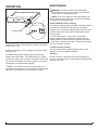
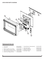
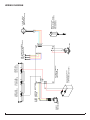
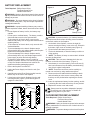
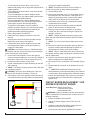
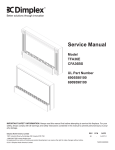
Service Manual
Model
TFA36E
CFA36BS
UL Part Number
6905580100
6909590100
IMPORTANT SAFETY INFORMATION: Always read this manual first before attempting to service this fireplace. For your
safety, always comply with all warnings and safety instructions contained in this manual to prevent personal injury or property damage.
Dimplex North America Limited
1367 Industrial Road Cambridge ON Canada N1R 7G8
1-888-346-7539 www.dimplex.com
In keeping with our policy of continuous product development, we reserve the right to make changes without notice.
© 2011 Dimplex North America Limited
REV
PCN
DATE
00
-
3-OCT-11
7400510000R00
TABLE OF CONTENTS
OPERATION. . . . . . . . . . . . . . . . . . . . . . . . . . . . . . . . . . . . . . . . . . . . . . . . . . . . . . . . . 3
Maintenance . . . . . . . . . . . . . . . . . . . . . . . . . . . . . . . . . . . . . . . . . . . . . . . . . . . . . . 3
Exploded Parts Diagram. . . . . . . . . . . . . . . . . . . . . . . . . . . . . . . . . . . . . . . . . . 4
Wiring Diagram. . . . . . . . . . . . . . . . . . . . . . . . . . . . . . . . . . . . . . . . . . . . . . . . . . . . 5
BATTERY REPLACEMENT. . . . . . . . . . . . . . . . . . . . . . . . . . . . . . . . . . . . . . . . . . . . . 6
Flicker MOTOR REPLACEMENT . . . . . . . . . . . . . . . . . . . . . . . . . . . . . . . . . . . . . . 6
LIGHT HARNESS REPLACEMENT. . . . . . . . . . . . . . . . . . . . . . . . . . . . . . . . . . . . . . . 8
CIRCUIT BOARD REPLACEMENT / LED DRIVER PCB CIRCUIT BOARD . . . . . . . 9
Troubleshooting Guide. . . . . . . . . . . . . . . . . . . . . . . . . . . . . . . . . . . . . . . . . . . 11
Always use a qualified technician or service agency to repair this fireplace.
! NOTE: Procedures and techniques that are considered important enough to emphasize.
CAUTION: Procedures and techniques which, if not carefully followed, will result in damage to the equipment.
Warning: Procedures and techniques which, if not carefully followed, will expose the user to the risk of fire, serious
injury, or death.
2
www.dimplex.com
OPERATION
Maintenance
Figure 1
A
Charging Cord
B
This electric fireplace is operated by a momentary switch
located on the bottom of the fireplace, under the right hand
corner (Figure 1-A).
Press the momentary switch to toggle the fireplace’s flame
effect on or off.
The battery charge LEDs (Figure 1-B) will indicate the
charge level of the battery. The LEDs read green, yellow
and red from right to left. Once the red battery charge LED
is lit, the electric fireplace should be plugged in to recharge.
The fireplace can operate while charging.
WARNING: Disconnect power before attempting
any maintenance or cleaning to reduce the risk of fire,
electric shock or damage to persons.
! NOTE: Even if the fireplace is not used regularly, the
battery should be fully recharged at minimum every three
(3) months to prolong battery life.
Partially Reflective Glass Cleaning
The partially reflective glass is cleaned in the factory during
the assembly operation. During shipment, installation,
handling, etc., the partially reflective glass may collect dust
particles; these can be removed by dusting lightly with a
clean dry cloth.
To remove fingerprints or other marks, the partially
reflective glass can be cleaned with a damp cloth. The
partially reflective glass should be completely dried with a
lint free cloth to prevent water spots. To prevent scratching,
do not use abrasive cleaners.
Fireplace Surface Cleaning
Use only a damp cloth to clean painted surfaces of the
fireplace. Do not use abrasive cleaners.
Servicing
Except for battery replacement and cleaning described
above, an authorized service representative should perform
any other servicing.
! NOTE: The fireplace will shut off automatically if it is
unplugged during operation. The momentary On/Off Switch
will need to be activated to turn the fireplace on again.
3
Exploded Parts Diagram
3
10
7
2
8
5
1
4
6
Replacement Parts List
1.
2.
3.
4.
5.
6.
Flicker Motor. . . . . . . . . . . . . . . . . . . . . 3000240200KIT
Flicker Rod . . . . . . . . . . . . . . . . . . . . . . . 5901590100RP
Battery, 12V, 8Ah, .25” terminals. . . . . . . 3700150100RP
Switch, ON/OFF Momentary SPDT . . . . 2800220100RP
PCB; Driver Board; Charger; DC Jack . . 3000750100RP
AC/DC Power Supply with cord . . . . . . . 3700180100RP
7. Partially Reflective Glass Assembly . . . . 5901550100RP
8. LED Light Assembly . . . . . . . . . . . . . . . . 6908300100RP
9. Battery Wire Harness . . . . . . . . . . . . . . . 2500560100RP
10. Wall Mounting Bracket . . . . . . . . . . . . . . 1021650100RP
11. River Rocks, Large. . . . . . . . . . . . . . . . . 1400060100RP
4
www.dimplex.com
ON/OFF
SWITCH
P/N 2800220100
1 WATT LED
FLAME LIGHT
P/N 3700140100
12V, 8Ah SLA BATTERY
P/N 3700150100
UL APPROVED (COMPONENT)
BATTERY CHARGER /
LED DRIVER
CIRCUIT BOARD
1 WATT LED
FLAME LIGHT
P/N 3700140100
WIRE AND CONNECTORS
PART OF PCB
1 WATT LED
FLAME LIGHT
P/N 3700140100
DC JACK
RED, ORANGE AND GREEN
BATTERY LEVEL INDICATOR LED'S
SUPPLIED WITH PCB
POWER SUPPLY
INPUT: 120VAC, 50/60Hz
OUTPUT: 12VDC, 3A MAX
UL APPROVED
P/N 3700180100
FLICKER MOTOR
P/N 3000240200
(HARNESS INCLUDED)
Wiring Diagram
5
BATTERY REPLACEMENT
Tools Required: Phillips Screw Driver;
Flat Head Screw Driver
Needle Nosed Pliers
WARNING: Unplug or disconnect power before attempting any maintenance to reduce the risk of electric shock or
damage to persons.
WARNING: To prevent damage to the electric fireplace
and to prevent bodily harm, only use Dimplex replacement
rechargeable batteries.
WARNING: Improper handling of battery may result in
possible explosion hazard, electric shock and severe bodily
injury.
• Do not dispose of battery in a fire, the battery may
explode
• Do not open or mutilate battery. The battery contains
chemicals that are toxic to the eyes and skin
• To decrease risk of electric shock, remove wrist
watches and jewelry such as rings and bracelets when
replacing battery.
• To decrease risk of electric shock, only use tools with
insulated handles.
• To prevent damage to the electric fireplace and to
prevent bodily harm, only replace battery with Dimplex
replacement rechargeable batteries.
• To prevent damage to the electric fireplace and to
prevent bodily harm, only use Dimplex approved DC
power supply to power and recharge battery.
• To dispose of spent battery, return it to place of
fireplace purchase, deliver it to a local recycling facility
or ship it to Dimplex North America Limited in the
replacement battery packaging material.
1. Ensure the fireplace is turned OFF.
2. Unplug the Power Supply cord from the unit (if attached).
3. Carefully remove the River Rocks (media) from the
Media Tray on the front of the fireplace
4. Lift and remove the electric fireplace from the wallmounting bracket (Figure 2) and carefully place it
upright on a flat surface.
Figure 2
Wall
Segment
Figure 3
Battery
Terminals
Battery
Battery Cover
CAUTION: A protective barrier (i.e. blanket) between
the fireplace and work surface will help prevent scratches
on the work surface or the fireplace.
5. On the back of the fireplace, remove the eight (8)
screws securing the battery cover to the unit, located in
the bottom, right corner of the back panel (Figure 3).
6. Lift and remove the battery access cover.
7. Tilt the unit backwards, to allow the battery to slide out
of the opening.
! NOTE: The battery is heavy so ensure that it will slide
out onto the flat surface.
CAUTION: Take care not to damage the 2 wire connections on the left side of the battery. (Figure 3)
8. Once battery is out of the opening, remove the two (2)
wire lead connectors from the battery terminals taking
note of their original configuration.
! NOTE: These wire connectors can be carefully removed one at a time by using needle nosed pliers.
9. Reconnect the wire leads with black leading to black
and red leading to red to ensure correct polarity and
that they are not pinched when replacing the access
cover.
10. Insert the replacement battery into the opening, carefully orienting the wire leads so that they are not pinched.
11. Replace the access cover and screws.
Battery must be recycled or disposed of properly.
Check with your Local Authority or Retailer for
recycling advice in your area.
Flicker MOTOR REPLACEMENT
Front of Fireplace
Tools Required: Phillips Screw Driver;
Flat Head Screw Driver
Needle Nosed Pliers
WARNING: Unplug or disconnect power before attempting any maintenance to reduce the risk of electric shock or
damage to persons.
WARNING: To prevent damage to the electric fireplace
6
www.dimplex.com
and to prevent bodily harm, only use Dimplex replacement
rechargeable batteries.
WARNING: Improper handling of battery may result in
possible explosion hazard, electric shock and severe bodily
injury.
• Do not dispose of battery in a fire, the battery may
explode
• Do not open or mutilate battery. The battery contains
chemicals that are toxic to the eyes and skin
• To decrease risk of electric shock, remove wrist
watches and jewelry such as rings and bracelets when
replacing battery.
• To decrease risk of electric shock, only use tools with
insulated handles.
• To prevent damage to the electric fireplace and to
prevent bodily harm, only replace battery with Dimplex
replacement rechargeable batteries.
• To prevent damage to the electric fireplace and to
prevent bodily harm, only use Dimplex approved DC
power supply to power and recharge battery.
• To dispose of spent battery, return it to place of
fireplace purchase, deliver it to a local recycling facility
or ship it to Dimplex North America Limited in the
replacement battery packaging material.
1. Ensure the fireplace is turned OFF.
2. Unplug the Power Supply cord from the unit (if attached).
3. Carefully remove the River Rocks (media) from the
Media Tray on the front of the fireplace
4. Lift and remove the electric fireplace from the wallmounting bracket (Figure 2) and carefully place it
upright on a flat surface.
CAUTION: A protective barrier (i.e. blanket) between
the fireplace and work surface will help prevent scratches
on the work surface or the fireplace.
5. On the back of the fireplace, remove the eight (8)
screws securing the battery cover to the unit, located in
the bottom, right corner of the back panel (Figure 3).
6. Lift and remove the battery access cover.
7. Tilt the unit backwards, to allow the battery to slide out
of the opening.
! NOTE: The battery is heavy so ensure that it will slide
out onto the flat surface.
CAUTION: Take care not to damage the 2 wire connections on the left side of the battery. (Figure 3)
8. Once battery is out of the opening, remove the two (2)
wire lead connectors from the battery terminals taking
note of their original configuration.
! NOTE: These wire connectors can be carefully removed one at a time by using needle nosed pliers.
9. Set the Battery aside.
10. Remove the remainder of the 17 screws which secure
the back panel on to the fireplace. 3 along the top; 3
along the right (battery side); 5 along the left (switch
side); and 6 on the bottom lip of the back panel.
Figure 4
LED
Flicker Motor
Retaining Clip
Circuit Board
11. Lift the back panel off the unit, exposing the internal
components and set it aside.
12. Looking at the unit from behind, locate the flicker motor
on the left beside the circuit board. (Figure 4) Unplug
the motor wire connector from the circuit board and
unhook the wires from the retaining clip(s) on the bottom panel.
13. Remove the flicker motor mounting bracket, by removing the 2 screws that attach to the bottom panel.
14. Grasp the flicker motor with the mounting bracket and
flicker rod still attached. Slide the flicker rod out of the
flicker assembly mounting bracket located on the opposite end.
15. Separate the flicker motor and flicker rod, by holding
the motor in one hand, grasping the rubber flicker connector and rod with the other hand, then twisting and
pulling them apart. Set the flicker rod with the rubber
connector aside.
16. Remove the 2 screws which secure the flicker motor to
the motor mounting bracket.
17. Replace with the new flicker motor onto the mounting
bracket and secure the motor to the bracket using the
original 2 screws.
18. Push the flicker rod with rubber connector onto the motor shaft and slide it back into the 2nd flicker assembly
mounting bracket.
! NOTE: Ensure that the rod has not been bent. If it has
it may cause noises and limited flame effect during usuage.
19. Secure the mounting bracket to the bottom panel of the
fireplace with the original 2 screws.
20. Re-assemble the remainder of the unit in reverse order.
! NOTE: Before placing the battery back into the opening, reconnect the wires in their original position with black
leading to black and red leading to red to ensure correct
polarity and that they are not pinched when replacing the
access cover.
7
LIGHT HARNESS REPLACEMENT
Tools Required: Phillips Screw Driver;
Flat Head Screw Driver
Needle Nosed Pliers
WARNING: Unplug or disconnect power before attempting any maintenance to reduce the risk of electric shock or
damage to persons.
WARNING: To prevent damage to the electric fireplace
and to prevent bodily harm, only use Dimplex replacement
rechargeable batteries.
WARNING: Improper handling of battery may result in
possible explosion hazard, electric shock and severe bodily
injury.
• Do not dispose of battery in a fire, the battery may
explode
• Do not open or mutilate battery. The battery contains
chemicals that are toxic to the eyes and skin
• To decrease risk of electric shock, remove wrist
watches and jewelry such as rings and bracelets when
replacing battery.
• To decrease risk of electric shock, only use tools with
insulated handles.
• To prevent damage to the electric fireplace and to
prevent bodily harm, only replace battery with Dimplex
replacement rechargeable batteries.
• To prevent damage to the electric fireplace and to
prevent bodily harm, only use Dimplex approved DC
power supply to power and recharge battery.
• To dispose of spent battery, return it to place of
fireplace purchase, deliver it to a local recycling facility
or ship it to Dimplex North America Limited in the
replacement battery packaging material.
1. Ensure the fireplace is turned OFF.
2. Unplug the Power Supply cord from the unit (if attached).
3. Carefully remove the River Rocks (media) from the
Media Tray on the front of the fireplace
4. Lift and remove the electric fireplace from the wallmounting bracket (Figure 2) and carefully place it
upright on a flat surface.
CAUTION: A protective barrier (i.e. blanket) between
the fireplace and work surface will help prevent scratches
on the work surface or the fireplace.
5. On the back of the fireplace, remove the eight (8)
screws securing the battery cover to the unit, located in
the bottom, right corner of the back panel (Figure 3).
6. Lift and remove the battery access cover.
7. Tilt the unit backwards, to allow the battery to slide out
of the opening.
! NOTE: The battery is heavy so ensure that it will slide
out onto the flat surface.
CAUTION: Take care not to damage the 2 wire connections on the left side of the battery. (Figure 3)
8. Once battery is out of the opening, remove the two (2)
wire lead connectors from the battery terminals taking
note of their original configuration.
! NOTE: These wire connectors can be carefully removed one at a time by using needle nosed pliers.
9. Set the Battery aside.
10. Remove the remainder of the 17 screws which secure
the back panel on to the fireplace. 3 along the top; 3
along the right (battery side); 5 along the left (switch
side); and 6 on the bottom lip of the back panel.
11. Lift the back panel off the unit, exposing the internal
components and set it aside.
12. Looking at the unit from behind, locate the light harness
plug on the main circuit board and unplug it from the
circuit board. (Figure 4)
13. Release the wires leads from the retaining clips and
wire ties, which secure them to the bottom panel of the
fireplace.
! NOTE: Be sure to cut the wire ties which secure the
light harness and the battery wire harness to the light housing panel taking care not to damage the wires.
14. Remove the 3 screws holding the light housing to the
bottom panel of the fireplace.
15. Remove the light harness assembly, and replace with
the new assembly.
16. Secure the new light housing panel to the bottom panel
with the original screws.
17. Secure the wires to the retaining clips and plug the light
harness connector to the circuit board.
18. Re-assemble the remainder of the fireplace in reverse
order.
! NOTE: Before placing the battery back in the housing/
brackets, ensure that the battery wire leads are re-connected in their original position with black leading to black and
red leading to red to ensure correct polarity and that they
are not pinched when replacing the access cover.
ON/OFF MOMENTARY SWITCH REPLACEMENT
Tools Required: Phillips Screw Driver;
Flat Head Screw Driver
Needle Nosed Pliers
WARNING: Unplug or disconnect power before attempting any maintenance to reduce the risk of electric shock or
damage to persons.
WARNING: To prevent damage to the electric fireplace
and to prevent bodily harm, only use Dimplex replacement
rechargeable batteries.
WARNING: Improper handling of battery may result in
possible explosion hazard, electric shock and severe bodily
injury.
• Do not dispose of battery in a fire, the battery may
explode
• Do not open or mutilate battery. The battery contains
chemicals that are toxic to the eyes and skin
8
www.dimplex.com
•
To decrease risk of electric shock, remove wrist
watches and jewelry such as rings and bracelets when
replacing battery.
• To decrease risk of electric shock, only use tools with
insulated handles.
• To prevent damage to the electric fireplace and to
prevent bodily harm, only replace battery with Dimplex
replacement rechargeable batteries.
• To prevent damage to the electric fireplace and to
prevent bodily harm, only use Dimplex approved DC
power supply to power and recharge battery.
• To dispose of spent battery, return it to place of
fireplace purchase, deliver it to a local recycling facility
or ship it to Dimplex North America Limited in the
replacement battery packaging material.
1. Ensure the fireplace is turned OFF.
2. Unplug the Power Supply cord from the unit (if attached).
3. Carefully remove the River Rocks (media) from the
Media Tray on the front of the fireplace
4. Lift and remove the electric fireplace from the wallmounting bracket (Figure 2) and carefully place it
upright on a flat surface.
CAUTION: A protective barrier (i.e. blanket) between
the fireplace and work surface will help prevent scratches
on the work surface or the fireplace.
5. On the back of the fireplace, remove the eight (8)
screws securing the battery cover to the unit, located in
the bottom, right corner of the back panel (Figure 3).
6. Lift and remove the battery access cover.
7. Tilt the unit backwards, to allow the battery to slide out
of the opening.
! NOTE: The battery is heavy so ensure that it will slide
out onto the flat surface.
CAUTION: Take care not to damage the 2 wire connections on the left side of the battery. (Figure 3)
8. Once battery is out of the opening, remove the two (2)
wire lead connectors from the battery terminals taking
Figure 5
note of their original configuration.
! NOTE: These wire connectors can be carefully removed one at a time by using needle nosed pliers.
9. Set the Battery aside.
10. Remove the remainder of the 17 screws which secure
the back panel on to the fireplace. 3 along the top; 3
along the right (battery side); 5 along the left (switch
side); and 6 on the bottom lip of the back panel.
11. Lift the back panel off the unit, exposing the internal
components and set it aside.
12. Looking at the unit from behind, locate the ON/OFF
switch on the left side of the bottom panel.
13. Disconnect the wire lead connectors on the switch
coming from the circuit board noting the original configuration. (Figure 5).
! NOTE: Using a flat head screwdriver gently pry between the end of the connector and the switch to release
the wires.
! NOTE: Try not to reverse the two black wires on the
switch.
14. Remove the switch from the bottom panel by depressing the 4 mounting tabs and pushing the switch outward through the bottom panel of the fireplace.
! NOTE: Pliers or a flat head screw driver may be helpful in getting a better grasp or putting more pressure on the
tabs to release them.
15. Push the new switch into place through the bottom
panel according to the original position.
16. Re-connect the wire connectors from the board. (Figure
5)
17. Re-assemble the remainder of the fireplace in reverse
order.
18. ! NOTE: Before placing the battery back in the
housing/brackets, ensure that the battery wire leads are
re-connected in their original position with black leading
to black and red leading to red to ensure correct polarity and that they are not pinched when replacing the
access cover.
CIRCUIT BOARD REPLACEMENT / LED
DRIVER PCB CIRCUIT BOARD
ON/OFF
SWITCH
Tools Required: Phillips Screw Driver;
Flat Head Screw Driver
Needle Nosed Pliers
WARNING: Unplug or disconnect power before attempting any maintenance to reduce the risk of electric shock or
damage to persons.
1. Ensure the fireplace is turned OFF.
2. Unplug the Power Supply cord from the unit (if attached).
3. Carefully remove the River Rocks (media) from the
Media Tray on the front of the fireplace
4. Lift and remove the electric fireplace from the wall9
mounting bracket (Figure 2) and carefully place it on a
flat surface with the partially reflective glass side down.
CAUTION: A protective barrier (i.e. blanket) between
the fireplace and work surface will help prevent scratches
on the work surface or the fireplace.
5. On the back of the fireplace, remove the eight (16)
screws from the battery access cover and the battery
mounting brackets located in the bottom, right corner of
the back panel (Figure 3).
6. Lift and remove the battery access cover.
7. Lift and remove the battery out of the housing.
! NOTE: The battery is heavy so you will need to use
the brackets for leverage to lift it out of the opening. A
flat head screwdriver may be helpful for additional leverage behind the battery bracket when lifting the battery and
brackets out of the fireplace.
CAUTION: Take care not to damage the 2 wire connections on the left side of the battery Figure 8).
8. Once battery is out of the opening, remove the two (2)
wire lead connectors from the battery spade connectors taking note of their original configuration (Figure 4).
! NOTE: These wire lead connectors can be pulled off
by using needle nosed pliers to carefully pull the connectors, or a flat head screw driver to pry the connectors off the
spades on the battery.
9. Set the Battery aside.
10. Remove the remainder of the (17) screws which secure
the back panel on to the fireplace. (3) along the top; (3)
along the right (battery side); (5) along the left (switch
side); and (6) on the bottom lip of the back panel.
11. Lift the back panel off the unit, exposing the internal
components and set it aside.
12. Looking at the unit from behind, locate the circuit board
(control panel), on the left hand side of the bottom
panel.
13. Unplug the wire harness plug connectors on the circuit
board (flicker motor; LED light harness, battery wire
harness).
14. Guide the battery charger input jack out from the left
side of the bottom panel by sliding it up towards you.
15. Disconnect the wire lead connectors coming from the
circuit board to the switch noting the original configuration.
! NOTE: Pliers can be used for a better grip on the connector, or a flat head screw driver can be used to carefully
pry up between the switch and connector if you are unable
to pull it off.
! NOTE: Try not to reverse the two black wires on the
switch. Their positioning on the circuit board to the switch
is: (Figure 5)
• Red-1, Black-2 goes to the side of the switch farthest
from the circuit board, Black-2 on the spade in the center of the switch and Red-1 on the spade on the right
side;
•
Black-3, Yellow-4 goes to the side of the switch closest
to the circuit board, Black-3 on the spade in the center
of the switch and Yellow-4 on the spade on the right
side of the switch.
16. Carefully pull the (3) charge level indicator lights with
wires out from their mounting clips near the switch
noting their original order, (Green in the clip to the left
closest to the switch, Yellow in the center; Red in the
clip on the right).
! NOTE: There is rubberized glue securing these in the
clip. When pulling on the indicator lights, the glue will come
off with the bulb & wires.
! NOTE: If necessary, using pliers may allow for a better grip when pulling these bulbs out.
17. Remove the circuit board from the mounting clips
located on the 4 corners of the board. Use a pair of pliers to pinch the tip of each mounting clip or cut the tabs
off so the original board can be pulled off.
18. Push the remainder of the old tabs out through the bottom panel and replace with the new tabs provided with
the replacement circuit board.
19. Line up the 4 corners of the replacement board to the
(4) mounting tabs and carefully push the new board
down onto the tabs.
20. Connect all of the wires and harnesses according to
their original configuration.
! NOTE: Ensure that the switch wires and the battery
level indicator lights are in their correct order and locations
as described in step 15 and 16.
21. Re-assemble the remainder of the fireplace in reverse
order.
! NOTE: Before placing the battery back in the housing/
brackets, ensure that the battery wire leads are re-connected in their original position with black leading to black and
red leading to red to ensure correct polarity and that they
are not pinched when replacing the access cover.
10
www.dimplex.com
Troubleshooting Guide
Problem
Cause
Solution
Appearance
Fireplace does not turn On
Improper operation
Refer to Operation Section
Battery not Charged
Charge Battery
Loose wiring
Check wiring connections
Dead Battery
Replace Battery
Defective LED PCB
Replace LED PCB
Flame Frozen
Defective flicker motor
Replace flicker motor
Loose wiring
Check wiring connections
Flame not bright or flame not
visible
Loose wiring
Check wiring connections
Defective light harness
Replace light harness
Flame Shudder
Defective flicker motor
Replace flicker motor
11