1
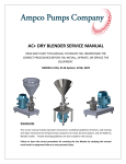
MANUAL
CARAVAN
RM 4212
RM 4213
Deutsch
Seite
1
Svenska
sida
32
English
page
7
Dansk
side
38
Français
page
14
Norsk
side
44
Italiano
pagina
20
Nederlands
pag.
50
Español
pagina
26
Suomi
sivu
56
821 2649-01
Typ C 40/ 110
DES/TB 07/97
www.vwT4camper.info - a useful website for owners and enthusiasts of VW T4 Transporter Campervans
OPERATING AND INSTALLATION INSTRUCTIONS FOR
ELECTROLUX REFRIGERATORS
INTRODUCTION
CONTENTS
We are pleased that you have chosen this refrigerator and
hope you will derive much satisfaction from using it, but first
a few well-meant words of advice:
OPERATING INSTRUCTIONS . . . . . . . . . . . . . . . . . . . . . 8
CONTROLS . . . . . . . . . . . . . . . . . . . . . . . . . . . . . . . . . . . . . 8
It is important to read through these instructions carefully
before using the refrigerator.
STARTING THE REFRIGERATOR . . . . . . . . . . . . . 8
WINTER OPERATION . . . . . . . . . . . . . . . . . . . . . . . . . . 8
To ensure good refrigeration and economical operation, the
refrigerator must be installed and used as described in
these instructions.
REGULATING THE TEMPERATURE. . . . . . . . . . . 8
TRAVEL CATCH . . . . . . . . . . . . . . . . . . . . . . . . . . . . . . . . 9
The refrigerator is designed for building-in to leisure
vehicles such as caravans or motorhomes.
FOOD STORAGE . . . . . . . . . . . . . . . . . . . . . . . . . . . . . . . 9
The appliance is certified according to the EU-Gas-Directive
90/396/EEC.
ICE-MAKING . . . . . . . . . . . . . . . . . . . . . . . . . . . . . . . . . . . . 9
DEFROSTING . . . . . . . . . . . . . . . . . . . . . . . . . . . . . . . . . . . 9
TRANSIT DAMAGE
CLEANING THE REFRIGERATOR . . . . . . . . . . . . . 9
Inspect the refrigerator for damage. Transit damage must
be reported to whoever is responsible for delivery not later
than seven days after the refrigerator was delivered.
TURNING OFF THE REFRIGERATOR . . . . . . . . . 9
IF THE `FRIDGE FAILS TO WORK. . . . . . . . . . . . . 9
DATA PLATE
MAINTENANCE . . . . . . . . . . . . . . . . . . . . . . . . . . . . . . . 10
Check the data plate, inside the refrigerator, to ensure that
you have received the right model.
SOME USEFUL HINTS . . . . . . . . . . . . . . . . . . . . . . . 10
The right gas pressure is 30 mbar.
GUARANTEE AND SERVICE. . . . . . . . . . . . . . . . . 10
The right voltage is 230 volts.
TECHNICAL DATA . . . . . . . . . . . . . . . . . . . . . . . . . . . 10
The data plate contains e. g. the following details:
INSTALLATION INSTRUCTIONS . . . . . . . . . . . . . . . . 10
Model designation RM .........................
REPOSITIONING THE HINGES . . . . . . . . . . . . . . 10
Product number .................................
Serial number
DOOR PANEL. . . . . . . . . . . . . . . . . . . . . . . . . . . . . . . . . 10
.................................
BUILDING-IN. . . . . . . . . . . . . . . . . . . . . . . . . . . . . . . . . . 11
VENTILATION OF THE UNIT . . . . . . . . . . . . . . . . . 11
Since these details will be needed if you have to contact
service personnel, it is a good idea to make a note of them
here.
LP GAS CONNECTION . . . . . . . . . . . . . . . . . . . . . . . 11
ELECTRICAL CONNECTION . . . . . . . . . . . . . . . . . 12
MOUNTING OF FRONT FRAME. . . . . . . . . . . . . . 13
7
www.vwT4camper.info - a useful website for owners and enthusiasts of VW T4 Transporter Campervans
OPERATING INSTRUCTIONS
8. Keep the (D) button pressed for a further 10 to 15 sec.
to active the flame failure device, then release it.
CONTROLS
If you have Model RM 4212 proceed as follows:
3. Turn on the gas supply by pressing the (D) knob and
turning it to the position
The refrigerator can be run on either 230 V, 12 V or LP gas.
Changing between these modes of operation is carried out
by means of the controls of the control panel shown in fig 3.
4. Set the thermostat knob (E) to the highest setting.
5. Keeping the flame failure device buttom (D) pressed,
operate the igniter (G) until the flame lights.
Two rocker switches are used to select the electric power
supply, one for 230 V (B) and one for 12 V (A).
6. Keep the (D) buttom pressed for a further 10 to 15 seconds then release it.
Refrigerator temperature is controlled by a thermostat (C)
when the unit runs on 230 V. The gas supply is turned
on/off by means of the knob (D). When lighting the gas, one
must press in the knob as explained further on.
The flame can be observed in a wiewing glass inside the
refrigerator at the bottom left (RM4212).
To terminate gas operation, turn knob (D) to ``●'' and (when
applicable) set switch (F) to ``0''.
Refrigerator temperature is controlled by a thermostat (E)
when the refrigerator runs on LP gas. Please note that the
thermostat has no ``off'' position.
230 V Operation
In model RM 4213, the gas flame is electronically lit, monitored and relit if necessary. For this the toggle switch (F)
should be ``on'' during gas operation.
● Turn off gas or 12 V operation when applicable.
● Turn the knob (C) of the thermostat to its highest (coldest) position.
An indicator lamp in the switch flashes when the automatic
igniter attempts to light the burner. Otherwise this lamp is
off.
● Set switch (B) to position I. The switch will light up green
when the power supply is connected.
In model RM 4212 a manual piezo-eletric igniter is used.
When the button (G) is pressed, sparks are generated at
the burner.
12 V Operation
Only operate your refrigerator on 12 V when the engine of
the vehicle is running - otherwise your battery will soon be
discharged.
Inside the refrigerator at bottom left is a sight glass for the
burner. A blue light can be seen through it when the flame
is alight. (RM 4212)
● If applicable, turn off the gas operation.
● Set the 12 V rocker switch (A) to I. The switch will light
up red when the power supply is connected.
STARTING THE REFRIGERATOR
The position numbers refer to fig. 3.
WINTER OPERATION
Please check that the ventilation grilles or the flue outlet are
not blocked by snow, leaves etc.
Caution!
Only use one source of energy at a time
ELECTROLUX ventilation grilles A 1620 (fig 2), can be
fitted with winter covers, model WA 120, to protect the
cooling unit against cold air. The covers may be fitted when
the outside temperature is below approx. 10°C and should
be fitted when the temperature is below the freezing point.
LP Gas operation
After initial installation, servicing, or changing gas cylinders
etc., the gas pipes may contain some air which should be
allowed to escape by briefly turning on the refrigerator or
other appliances. This will ensure that the flame lights
immediately.
We suggest that you fit the winter covers also in the case
that the vehicle is laid up during the winter months.
To start gas operation:
REGULATING THE TEMPERATURE
1. Open the shut-off valve of the gas bottle (check that there
is enough gas). Open any on-board shut-off valve.
The position number refers to fig. 3.
2. Check that the switches for mains and 12 V operation are
off.
It will take a few hours for the refrigerator to reach normal
operating temperature. So we suggest you start it well in
advance of a trip and if possible store it with precooled
foodstuffs.
If you have Model RM 4213 proceed as follows:
3. Turn on the gas supply by pressing the (D) knob and
turning it to the position
On 230 V operation the refrigerator is controlled by a thermostat and the thermostat knob (C) should be set at 3-5. If
a lower (colder) temperature is desired, set the thermostat
to a higher figure.
4. Set the thermostat knob (E) to the highest setting.
5. Depress switch (F). A light in the switch should now start
to flash, indicating that sparks are being generated at the
burner.
On 12 V operation the refrigerator works continuously.
On LP gas operation the refrigerator temperature is regulated by the gas thermostat (E), which should be set at 3-5. If
a lower (colder) temperature is desired, set the thermostat
to a higher figure.
6. Press the (D) button. This opens the flame failure device
and allows gas to flow to the burner.
7. When the flame lights, the sparking stops automatically
and the switch stops flashing.
8
www.vwT4camper.info - a useful website for owners and enthusiasts of VW T4 Transporter Campervans
TRAVEL CATCH
CLEANING THE REFRIGERATOR
Make sure that the travel catch is engaged when the caravan is on the move, (fig 1).
Clean the inside of the refrigerator regularly to keep it fresh
and hygienic.
The travel catch at the top of the door can be set in two
different positions. In one position the door is held tightly
shut. In the other position the door is secured ajar so that
the refrigerator can be aired when not in use.
Soak a cloth in a solution consisting of a teaspoon of bicarbonate of soda to half a litre of warm water. Wring out the
cloth and use it to clean the interior of the refrigerator and
its fittings.
FOOD STORAGE
Never use detergents, scouring powder, strongly scented
products or wax polish to clean the interior of the refrigerator as they may damage the surfaces and leave a strong
odour.
Always keep food in closed containers. Never put hot food
in the refrigerator; allow it to cool first.
Never keep items in the refrigerator which might give
off flammable gases.
The exterior of the refrigerator should be wiped clean now
and again, using a damp cloth and a small quantity of detergent. But not the door gasket, which should only be cleaned
with soap and water and then thoroughly dried.
The 2-star (**) frozen food compartment is intended for the
storage of frozen food and for making ice. It is not suitable
for freezing items of food.
Never put bottles or cans of fizzy drinks in the frozen food
storage compartment as they may burst when freezing. Also
don't give children ice lollies straight from the frozen food as
they could cause frost burns.
TURNING OFF THE REFRIGERATOR
If the refrigerator is not to be used for some time:
Most kinds of frozen food can be stored in the frozen food
compartment for about a month. This period of time may
vary, however, and it is important to follow the instructions
on the individual packets.
1. Set any switches to 0.
2. Set the gas valve (D) to ●.
3. Shut off any on-board valve in the gas line to the refrigerator.
ICE MAKING
4. Empty the refrigerator. Defrost and clean it as described
earlier. Leave the doors of the refrigerator and the frozen
food compartment ajar. Use the travel catch to hold in
this position.
It is practical to make ice during the night - then the refrigerator is less demanded and the cooling unit has more reserves. Fill the ice tray to just below the brim with drinking
water and place it on the freezer shelf.
5. When the vehicle is laid up for a long period of time
(e.g. during the winter months), we suggest fitting the
winter covers WA 120, fig. 2, onto the vent grills.
To speed up the ice making, one can spill one or two
spoonfuls of water on the freezer shelf to improve the contact to the ice tray. If you have more than one ice tray it is a
good idea to make ice in advance and save the frozen trays
in the frozen food compartment.
IF THE `FRIDGE FAILS TO WORK
DEFROSTING
Check the following points before calling a service technician:
Frost will gradually accumulate on the refrigerating surfaces. It must not be allowed to grow too thick as it acts as
an insulator and adversely affects refrigerator perfor-mance.
1. That the STARTING THE REFRIGERATOR instructions
have been followed.
Check the formation of frost regularly every week and when
it gets about 3 mm thick, defrost the refrigerator.
2. The refrigerator is level.
To defrost the `fridge, turn it off and remove the ice tray and
all food items. Warning: normally the temperature of items
of fozen foods would rise unduly during defrosting and so
they should be consumed within 24 h or discarded.
4. If the refrigerator fails to work on gas, check:
3. If it is possible to start the refrigerator on any of the
connected sources of energy.
● That the gas bottle is not empty.
● That all LP-gas valves are open.
5. If the refrigerator fails to work on 12 V, check:
Do not try to accelerate defrosting by using any kind of
heating appliance, as this might damage the plastic surfaces of the refrigerator. Neither should any sharp objects
be used to scrape off the ice.
● That the 12 V supply is connected to the refrigerator.
● That the fuse on the 12 V supply is intact.
● That the 12 V switch is on.
6. If the refrigerator fails to work on 230 V, check:
The defrost water runs from a collector channel to a receptacle at the rear of the refrigerator where it evaporates.
Defrost water in the freezer compartment should be mopped up with a cloth.
● That the 230 V supply is connected to the refrigerator.
● That the fuse is intact.
If the refrigerator is not cold enough it may be because:
When the ice has melted, wipe the refrigerator dry and
restart it. Place the food items back inside but wait until the
refrigerator is cold before making ice cubes.
1. The ventilation is inadequate owing to reduced area of
the ventilation passages (partial blockage of grilles from
wire mesh etc).
9
www.vwT4camper.info - a useful website for owners and enthusiasts of VW T4 Transporter Campervans
2. The evaporator is frosted up.
TECHNICAL DATA
3. The temperature control setting is incorrect.
Overall dimensions, refrigerator
Height . . . . . . . . . . . . . . . . . . . . . . . .618
Width
. . . . . . . . . . . . . . . . . . . . . . . .486
Depth (incl. cooling unit)
without door. . . . . . . . . . . . .435
with door. . . . . . . . . . . . . . . .474
4. The gas pressure is incorrect - check the pressure regulator at the gas container.
5. The ambient temperature is too high.
6. To much food is loaded at one time.
7 . The door is not properly closed or the magnetic sealing
strip is defective.
RM 4212/ 13
mm
mm
mm
mm
Build-in dimensions
Height . . . . . . . . . . . . . . . . . . . . . . . .620 mm
Width
. . . . . . . . . . . . . . . . . . . . . . . .490 mm
Depth . . . . . . . . . . . . . . . . . . . . . . . .450 mm
8. More than one source of energy is used at the same
time. If the refrigerator still does not work properly, call a
service technician.
Capacity
gross
. . . . . . . . . . . . . . . . . . . . . . . . . 60
net
. . . . . . . . . . . . . . . . . . . . . . . . . 51
frozen food compt . . . . . . . . . . . . . . . . . 6
Weight (without packaging) . . . . . . . . . . . . . 21
The sealed cooling system must not be opened, since
it is under high pressure.
lit.
lit.
lit.
kg
Electrical data
Input 230 V . . . . . . . . . . . . . . . . . . . . . 105 watt
12 V . . . . . . . . . . . . . . . . . . . . . 100 watt
Energy consumption /24 h. . . . . . . . .2,3 kWh
MAINTENANCE
Concerning gas- and electric installations, only authorized
experts are allowed to carry out maintenance and repair
works. Besides, it is recommendable to contact an authorized service if it comes to repair works.
LP gas data
Input
. . . . . . . . . . . . . . . . . . . . . . . . 186 watt
ditto, low flame . . . . . . . . . . . . . . . . . . . .86 watt
Energy consumption /24 h. . . . . . . .0,24 kg
According to the valid regulations G607 of DVGW, the gas
installation as well as the connect flue oulets are to be
checked every two years by an expert (this has to be
arranged by the person responsible).
Cooling medium Ammonia (R 717)
SOME USEFUL HINTS
INSTALLATION INSTRUCTIONS
Make sure that:
REPOSITIONING THE HINGES
The door hinges can be moved to the opposite side in the
following way:
● The refrigerator is not operating on 12 V when the vehicle is parked, otherwise you will drain the car bat-tery in
a short time.
● Unscrew the upper hinge pin, taking care not to lose the
set of washers and bushes.
● Defrosting is carried out periodically.
● Lift the door from the lower hinge pin.
● The refrigerator is left with the door(s) ajar when it is not
to be used for some time.
● Unscrew the pin and mount it on the opposite side hinge.
● Unscrew the travel catch and mount it on the opposite
side.
● Liquids or items with a strong odour are well packa-ged.
● The ventilation openings are unobstructed.
● The door is secured by means of the travel catch when
the caravan is on the move.
● On the upper edge of the door are two plastic inserts for
the alternative holes of the travel catch. Pry out carefully
and exchange
● Only one mode of operation at a time is used to run the
refrigerator.
● Fit the door on the pin and reassemble the pin with
washers and bushes in its new place.
● Check that the door closes properly and seals all round.
DOOR PANEL
GUARANTEE AND SERVICE
The door panel can easily be mounted or changed. The
dimensions of the panel must be:
The refrigerator is guaranteed for one full year on condition
that it is used in a correct manner and in accordance with
these operating and installation instructions.
Height ..........................532 +/- 1mm
Width .......................... 453 +/- 1mm
Thickness .................... max 3,8 mm
It is also embraced by a European guarantee as described
in the brochure supplied with the refrigerator.
● Remove the door, see REPOSITIONING THE HINGES.
Service and spare sparts are obtainable from your dealer or
Electrolux - consult the telephone directory
● Remove the lower trim moulding and then withdraw the
panel by sliding it downwards.
● Fit new panel in place and slide it up as far as possible.
● Fit the trim moulding back in place.
10
www.vwT4camper.info - a useful website for owners and enthusiasts of VW T4 Transporter Campervans
BUILDING-IN
Ventilation grilles Fig. 2
The refrigerator is intended for installation in a caravan or
motorhome, and the description relates to this application.
The openings in the caravan wall must be fitted with the
Electrolux ventilation systems.
Fitting the grilles, model A 1620, which were specially
developed by Electrolux for this purpose (shown as D in fig.
6). It is a good idea, to install the frame R 1640 (A in the
same figure), at the same time. Then the grilles can be
easily removed which permits inspection and small repairs
to be carried out without the necessity for removing the
refrigerator from the recess.
The refrigerator must not be exposed to radiated heat from
hot objects (e.g. below a cooker without proper heat shielding).
Excessive heat irradiation impairs performance and leads to
increased energy consumption. For this reason the refrigerator should be installed if possible not at the entrance side
of the vehicle - normally orientated south and often with an
awning - which would impair the dispersion of heat and
combustion gases from the ventilation openings.
If there is no outer grille at floor level where leaking gas can
escape, a 40 mm hole to the outside should be made in the
floor of the recess to drain any unburnt gas to the outside
gas.
It is not a good practice to install the refrigerator so that the
vent openings are covered by the vehicle's entrance door
when this is open. This would reduce the ventilation air flow
to the cooling unit and reduce refrigeration performance.
Fit the hole with wire mesh and an angled plate to protect
from stones, mud etc.
Removal of flue gases
The enclosure
The ventilation passage at the rear of the recess, between
the outer wall of the vehicle and the refrigerator (fig. 6), is
sealed off against the living space, and so cold draughts are
excluded (winter camping) and no flue gases can penetrate
into the vehicle. Thus a special flue outlet is no longer
necessary - the gases are dispersed through the upper vent
grille.
The refrigerator must be installed in an enclosure, the
dimensions of which are shown in TECHNICAL DATA.
The bottom of the enclosure must be horizontal and even
so that the refrigerator can be easily pushed into place. It
must be sturdy enough to carry the wieght of the refrigerator.
Note: With this mode of installation the same type of grilles
(without an integrated flue outlet), should be installed at the
upper as well as at the lower vent open-ning. The angled
T-piece for the flue tube (when delivered) should not be
used in this case.
Battens must be installed at the enclosure and fitted with
sealing strips, as shown in fig. 4.
Slide in the refrigerator until it is flush with the front of the
recess. There must be 10-20 mm free space behind the
refrigerator.
The top of the enclosure above the flue tube (I), fig. 6,
should be covered with aluminum sheet metal, as indicated
in (B), to facilitate the heat dispersion.
Four fasteners are fitted in plastic bushings in the side walls
of the fridge, fig. 7. They are used for securing the refrigerator in the enclosure.
In fig. 6 the letters have the following meaning:
A. Frame R 1640 for the grilles
B. Aluminum cladding
C. Condenser of cooling unit
D. Vent grill A 1620
E. Sealing profile (optional extra)
Width 486 mm, Electrolux art. nr. 295 1147-10
F. Refrigerator rear wall
G. Wooden batten approx. 10 x 20 mm (see fig. 4)
H. Height of the enclosure (see TECHNICAL DATA)
I. Flue tube
The side walls of the enclosure and/or any wooden braces
installed to hold the refrigerator must be dimensioned to
seat the screws securely, also considering the forces due to
the movement of the vehicle.
With the refrigerator in place, drive the screws through the
bushings in the lining (Fig.7) of the refrigerator into the walls
of the enclosure. There must not be more than 3mm of
clearance between refrigerator and enclosure on each side.
If necessary, wooden strips or similar should be fitted.
Note: This is the only approved means of securing the
refrigerator to the enclosure and to the vehicle. Fasteners
penetrating other parts of the insulation (PU) foam of the
refrigerator might damage components like electric wiring
etc.
LP GAS CONNECTION
The refrigerator is designed for operation on LP gas of
Butane type the pressure of which must be 28 mbar for
Butane and 37 mbar for Propane. Check that this is stated
on the data plate.
VENTILATION OF THE UNIT
At high ambient temperatures the refrigeration unit will only
perform adequately when properly ventilated.
The refrigerator is not designed for operation on town gas or
natural gas.
The refrigeration unit is ventilated via two openings in the
wall of the caravan (see fig. 5). Fresh air enters through the
lower opening and warm air is discharged through the upper
one.
CAUTION! CHECK THAT THE GAS SUPPLIED TO THE
REFRIGERATOR IS AT THE CORRECT PRESSURE.
SEE THE REDUCING VALVE ON THE LP GAS
Locate the lower opening immediately above the floor of the
recess, and the upper one as high as possible above the
condenser (C) of the refrigeration unit, at least as shown in
fig. 6b but preferably as shown in fig. 6a.
The gas installation should only be carried out by an
authorised gas fitter. The supply pipe should preferably be
of copper. If any other material is used, it must be of a type
11
www.vwT4camper.info - a useful website for owners and enthusiasts of VW T4 Transporter Campervans
approved for use with continuously operating bottled- gas
appliances, and have threaded compression connections
throughout. PUSH-ON CONNECTIONS MUST NOT BE
USED (We do not approve the use of ``rubber'' type flexible
tubing for connecting permanently operating appliances of
this type in the United Kingdom). All connectors etc. should
be of a type specifically designed for the type and diameter
of the connection pipe used, and screwed joints should be
sealed with a joining compound approved for use with
bottled gas.
230 V Supplies.
Check that the voltage stated on the data plate is the same
as the mains voltage in use (230 V).
Electrical leads must be routed and secured so that
they cannot come into contact with hot or sharp parts
of the refrigerator.
The gas supply pipe should be connected to the gas inlet
pipe on the right hand side of the gas control valve by
means of a suitable threaded compression coupling.
12 V Supplies
Connect the refrigerator to the vehicle battery by a direct
cable. To avoid a voltage drop, the cross sectional area of
the connecting cable between battery and refrigerator must
be at least 2.5 mm2 if the distance is less than 9 meters,
and at least 4 mm2 if the distance is more than 9 meters
In making the connection to the refrigerator, a gas cock of
an approved type for use on LPG must be incorporated in
the supply line in a position which is readily accessible to
the user. For eventual servicing purposes, the union should
be on the outlet side of the cock and the pipework should
be positioned so as not to prevent the refrigerator from
being readily withdrawn.
To ensure satisfactory operation, the positive lead must be
fitted with a fuse rated at max. 16 A.
To prevent the refrigerator from draining the battery, make
sure that the current supplied to the caravan is cut off when
the vehicle engine is not running, for example by fitting an
ignition control relay.
ELECTRICAL CONNECTION
The electrical installation must be carried out in a proper
and durable manner, taking into account all relevant regulations and codes of practice. For mains voltage operation, it
is important that the circuit to and in the caravan is effectively earthed. ALL MAINS VOLTAGE WIRING IN THE
CARA-VAN MUST BE INSTALLED IN ACCORDANCE
WITH CURRENT I.E.E. REGULATIONS INCLUDING THE
USE OF AN OUTLET AND COUPLER TO BS4343/CEE17.
Diagramme for the mains installation: fig. 9
Diagramme for the 12 V installation:
fig. 10 (RM 4212), fig. 12 (RM 4213)
The notations in the wiring diagramme are:
A. Electronic igniter/reigniter
B. Electrode (at burner)
C. 12 V heating element
D. Switch for 12 V operation
E. Switch for reigniter (gas op.)
F. Electric thermostat
G. Heating element, 230 V
H. Switch for 230 V operation
J. Terminal block
L. Terminal block
For connection to a 230 V electricity supply, the refrige-rator
has a 3-core mains lead which is intended for connection to
a properly earthed plug and socket outlet or fused spur.
IMPORTANT: The wires in the mains lead of this appliance
are coloured in accordance with the following code:
GREEN-AND-YELLOW = EARTH
BLUE = NEUTRAL
BROWN = LIVE
12 V supply of reigniter (RM 4213)
As the colours of the wires may not correspond with the
coloured markings identifying the terminals in your plug, in
the United Kingdom, proceed as follows:
Fig. 12 shows the wiring diagramme of the refrigerator as
delivered. The 12 V supply enters at (L). The reigniter (A) is
fed via two wires (1) and (2) at terminal block (L).
The wire which is coloured GREEN-AND-YELLOW must be
connected to the terminal in the plug which is marked with
the letter E or by the earth symbol
or coloured green or
green-and-yellow.
It is advisable to feed the reigniter and the lighting from a
separate 12 V source. To do this: remove the wires (1) and
(2) and connect the supply as is shown in fig. 11.
The wire which is coloured BLUE must be connected to the
terminal which is marked with the letter N or coloured black.
In some executions there in an extra terminal block (J), of
fig. 12. In this case one disconnects the wires as said above
but connects the separate supply to (J).
The wire which is coloured BROWN must be connected to
the terminal which is marked with the letter L or coloured
red.
The reigniter should not be connected directly to a battery
charger but only over a battery.
WARNING! THIS APPLIANCE MUST BE EARTHED !
In the United Kingdom, the plug or circuit to the refrige-rator
must be fitted with a fuse not greater than 5 amps. If a 13
amp.(B.S.1363) fused plug is used, it should be fitted with a
3 amp. fuse. In other countries, the fuse rating will depend
upon the voltage and local practice.
12
www.vwT4camper.info - a useful website for owners and enthusiasts of VW T4 Transporter Campervans
MOUNTING OF FRONT FRAME
For models RM 4212F and RM4213F
F= Front frame
13
www.vwT4camper.info - a useful website for owners and enthusiasts of VW T4 Transporter Campervans
www.vwT4camper.info - a useful website for owners and enthusiasts of VW T4 Transporter Campervans
www.vwT4camper.info - a useful website for owners and enthusiasts of VW T4 Transporter Campervans
www.vwT4camper.info - a useful website for owners and enthusiasts of VW T4 Transporter Campervans