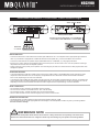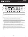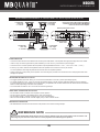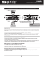
1
VERS.1.1
MAXXSONICS USA, INC.
1290 Ensell Road
Lake Zurich, Illinois 60047 USA
www.maxxsonics.com
N A N O NSC2100
N A N O N S C 475
V E R S T Ä R K E R
A M P L I F I E R S
DISTRIBUTION:
Audio Design GmbH
Am Breilingsweg 3
D-76709 Kronau (Germany)
Tel. +49 (0)7253 - 9465-0
Fax +49 (0)7253 - 946510
www.audiodesign.de
EINBAUANLEITUNG
INSTALLATION GUIDE
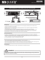
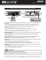
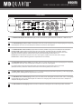
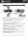
DEU SYSTEMANORDNUNG
Die gelungene Einrichtung einer jeden Autostereoanlage hängt von mehreren Faktoren ab wie Systemauslegung, Installationsausführung und
Systemeinstellung. Bitte berücksichtigen Sie, dass jedes System nur so gut sein kann wie sein schwächstes Glied.
Bitte berücksichtigen Sie, dass Systeme mit höherer Leistung nicht unbedingt nur zur Erzeugung hoher Schalldruckpegel dienen, sondern auch,
um eine größere Leistung im Frequenzspitzenbereich zu erzielen, damit musikalische Spitzen ohne Verzerrung sauber wiedergegeben werden
können.
Verstärker mit niedrigerer Leistung erreichen eher ihre Begrenzung, als ihre leistungsstärkeren Verwandten und können bei Übersteuerung
aufgrund der von einem begrenzten Signal erzeugten Oberschwingungen, die zur Überhitzung der Schwingspulen führen, Lautsprecherfehlfunktionen
hervorrufen.
Der Verstärker sollte immer mit vertikal verlaufenden Kühlrippen montiert werden, um die beste Kühlkonvektion zu erzielen und ein Überhitzen
zu vermeiden. Zwecks Zuverlässigkeit und geringerer Interferenzen der Audioanlage durch spannungserzeugende Komponenten des Fahrzeuges,
besorgen Sie sich bitte Cinch-Kabel bestmöglicher Qualität.
Es wird ausdrücklich empfohlen, den Verstärker mit den vier mitgelieferten Halterungsschrauben auf einer Faserplatte oder einer anderen stabilen
Trägerplatte zu montieren. Befestigen Sie den Verstärker nicht auf Metall, da dies Geräusche verursachen oder andere unerwünschte Effekte
verursachen kann. Bauen Sie den Verstärker waagrecht ein, um eine optimale Hitzeableitung zu gewährleisten. Den Verstärker an Lautsprechergehäusen
zu befestigen ist nicht zu empfehlen, da hierdurch Bauteile des Verstärkers beschädigt werden können. Wenn Sie einen Einbauplatz für den
Verstärker wählen, stellen Sie sicher, daß genügend Abstand zu Kabeln, Benzintank, elektrischen Bauteilen und den Bremsleitungen usw.
eingehalten wird.
ENG SYSTEM DESIGN
The success of any car stereo system relies on several factors, such as the system design, execution of the installation, and system setup. Please
remember that any system is only as good as its weakest link.
Please remember that higher power systems are not necessarily useful purely for high sound pressure levels, but also to establish a headroom
capability, to reproduce musical peaks cleanly without distortion.
Lower power amplifiers will clip earlier than their more powerful cousins, and cause loudspeaker failure when overdriven, due to the harmonics
generated by a clipped signal, thus overheating voice coils.
Amplifiers should be mounted with the fins running horizontally for best convection cooling, to minimize overheating. Purchase the
best quality RCA cables you can afford, for reliability and less engine noise interference in the audio system.
It is highly recommended that the amplifier be mounted to a board of MDF or other solid structure using the 4 mounting screws provided. Avoid
mounting the amplifier to metal as this can introduce noise and other unwanted issues. When mounting the amplifier, ensure that it is mounted
HORIZONTALLY for optimal heat dissipation. Mounting amplifiers to speaker enclosures is not recommended as this can cause damage to the
amplifier components. When choosing a location for mounting the amplifier, ensure that you check for clearance from wires, gas tank, electrical
devices and brake lines etc.
NSC2100/NSC475
INHALTSVERZEICHNIS
OWNER’S MANUAL IN ENGLISH ON PAGE 17
SICHERHEITSHINWEISE
3
INSTALLATIONSHINWEISE
4
2-KANAL VERSTÄRKER
6
Funktionen und Bedienelemente
6
Anschlussbeispiel 2-Kanal-Modus: 1 x Stereo System (Front oder Rear)
7
Anschlussbeispiel 1-Kanal-Modus: 1 x Mono Subwoofer gebrückt
8
4-KANAL VERSTÄRKER
9
Funktionen und Bedienelemente
9
Anschlussbeispiel 4-Kanal-Modus: 1 Stereo System (Front) und 1 x Stereo System (Rear)
10
Anschlussbeispiel 2-Kanal-Modus: 2 x Mono Subwoofer gebrückt
11
Anschlussbeispiel 3-Kanal-Modus: Stereo System und 1 x Mono Subwoofer gebrückt
12
TECHNISCHE DATEN
14
FEHLERBEHEBUNG
15
HINWEIS!
WICHTIGER HINWEIS ZUR INSTALLATION UND DEM BETRIEB IN NEUEREN FAHRZEUGEN!
In Fahrzeugen neueren Baujahrs (ab ca. 2002) kommen in der Regel computergestützte Diagnose- und Kontrollsysteme zum
Einsatz, u.a. mit CAN-BUS- und MOST-BUS-Schnittstellen. Durch die Installation des Car Audio Verstärkers kommt ein weiterer
Stromverbraucher an das 12 Volt Bordnetz des Fahrzeugs, der unter Umständen durch hohe Spannungsspitzen und durch einen
erhöhten Stromverbrauch das ab Werk installierte Diagnose- und Kontrollsystem stört, bzw. Fehlermeldungen verursacht. Dadurch
könnte, je nach Fahrzeugtyp und Hersteller, die Fahrsicherheit bzw. wichtige Sicherheitssysteme wie Airbags, Stabilitätskontrolle
und ähnliches gestört werden.
Sollten Sie den Verstärker in einem neueren Fahrzeug wie oben beschrieben betreiben wollen, gehen Sie bitte wie folgt vor:
• Lassen Sie die Installation nur von einem entsprechend geschulten Einbauspezalisten durchführen, am besten von
einer Service-Werkstatt, die auf die Wartung und Reparatur Ihres Fahrzeugs spezialisiert und mit der Technik des
Fahrzeugs vertraut ist.
• Nach der Installation sollte unter allen Umständen eine computergestützte Diagnose des Fahrzeugsystems von Ihrer
Service-Werkstatt durchgeführt werden, um eventuelle Störungen und Fehlermeldungen erkennen zu können.
• Sollte das Bordnetz bzw. die Sicherheitssysteme durch die Installation des Car Audio Verstärkers gestört werden,
können mit Hilfe von parallel geschalteten Pufferkondensatoren die etwaigen auftretenden Störungen im Bordnetz
ausgeglichen werden. Ein stabiler und sachgemäßer Betrieb des Fahrzeugs kann somit gewährleistet werden.
• Die beste Lösung stellt jedoch die Installation eines zweiten 12 Volt Stromnetzes für das Soundsystem dar, welches
unabhängig von der Fahrzeugelektrik betrieben werden kann und über eine eigene Batterieversorgung verfügt.
SUCHEN SIE IN JEDEM FALL IHRE SERVICE-WERKSTATT AUF UND LASSEN SIE SICH BERATEN!
BITTE BEWAHREN SIE DIE BEDIENUNGSANLEITUNG FÜR SPÄTERE ZWECKE AUF!
2
NSC2100/NSC475
SICHERHEITSHINWEISE
BITTE BEACHTEN SIE DIE FOLGENDEN HINWEISE VOR INBETRIEBNAHME!
DAS GERÄT NICHT AN STELLEN EINBAUEN, AN DENEN ES
HOHER FEUCHTIGKEIT ODER STAUB AUSGESETZT IST.
Bauen Sie das Gerät so ein, dass es vor hoher Feuchtigkeit und
Staub geschützt ist. Wenn Feuchtigkeit oder Staub in das Gerät
gelangen, kann es zu Betriebsstörungen kommen. Schäden am
Gerät, welche durch Feuchtigkeit hervorgerufen wurden, unterliegen nicht der Garantie.
DAS VON IHNEN ERWORBENE GERÄT IST NUR FÜR DEN
BETRIEB AN EINEM 12-V-BORDNETZ EINES FAHRZEUGS
AUSGELEGT. Andernfalls besteht Feuergefahr, die Gefahr eines
elektrischen Schlages oder anderer Verletzungen.
BITTE KEINE BEDIENUNG DES SOUNDSYSTEMS AUSFÜHREN, WELCHE VOM SICHEREN LENKEN DES FAHRZEUGS
ABLENKEN KÖNNTE. Führen Sie keine Bedienungen aus, die
Ihre Aufmerksamkeit längere Zeit in Anspruch nehmen. Stoppen
Sie besser das Fahrzeug an einer sicheren Stelle am Straßenrand,
bevor Sie solche Bedienungen ausführen. Andernfalls besteht
Unfallgefahr.
DAS GERÄT SOWIE ANDERE KOMPONENTEN DES SOUNDSYSTEMS AUSREICHEND BEFESTIGEN. Andernfalls könnten
sich die Geräte und Komponenten während der Fahrt lösen und
als gefährliche Geschosse im Fahrgastraum Beschädigungen
und Verletzungen hervorrufen.
DIE LAUTSTÄRKE NUR SO HOCH EINSTELLEN, DASS SIE
WÄHREND DER FAHRT NOCH AUSSENGERÄUSCHE WAHRNEHMEN KÖNNEN. Hochleistungsaudiosysteme in Fahrzeugen,
können den Schallpegel eines “Live-Konzertes” erzeugen. Dauerhaft extrem lauter Musik ausgesetzt zu sein kann den Verlust
des Hörvermögens oder Hörschäden zur Folge haben. Das Hören
von lauter Musik beim Autofahren kann Ihre Wahrnehmung
(Warnsignale) beeinträchtigen. Im Interesse der allgemeinen
Sicherheit empfehlen wir das Musikhören beim Autofahren mit
geringer Lautstärke. Andernfalls besteht Unfallgefahr.
BEIM BOHREN VON LÖCHERN, BESTEHENDE KOMPONENTEN, LEITUNGEN UND KABEL DES FAHRZEUGS NICHT
BESCHÄDIGEN. Wenn Sie bei der Installation Löcher in das
Fahrzeugchassis bohren, achten Sie unbedingt darauf die Kraftstoffleitungen, den Benzintank, elektrische Kabel und andere
Leitungen nicht zu beschädigen, zu berühren oder zu blockieren.
AUF KORREKTE ANSCHLÜSSE ACHTEN. Bei fehlerhaften
Anschlüssen besteht Feuergefahr, Kurzschlussgefahr und es
kann zu Schäden am Gerät kommen.
LÜFTUNGSÖFFNUNGEN UND KÜHLKÖRPER NICHT ABDECKEN. Andernfalls kann es zu einem Wärmestau im Gerät kommen
und es besteht Feuergefahr.
AUDIOKABEL UND STROMKABEL SOLLTEN NICHT ZUSAMMEN VERLEGT WERDEN. Bei der Installation des Audiokabels
zwischen dem Cinch-Ausgang des Autoradios und dem CinchEingang des Verstärkers im Fahrzeug ist darauf zu achten, dass
das Audio- und das Stromversorgungskabel möglichst nicht auf
der selben Seite des Fahrzeugs verlegt werden. Besser ist eine
räumlich getrennte Installation, im rechten und linken Kabelschacht
des Fahrzeugs. Damit wird das Überlagern von Störungen auf
das Audio-Signal verringert. Dieses gilt ebenfalls für das Verbindungskabel der beiliegenden Kabel-Fernbedienung. Das Kabel
sollte nicht auf der Seite der Stromversorgungsleitung verlegt
werden, sondern zusammen mit den Audiokabeln.
DAS GERÄT AUF KEINEN FALL ÖFFNEN. Andernfalls besteht
Unfallgefahr, Feuergefahr oder die Gefahr eines elektrischen
Schlages. Das Öffnen des Gerätes hat auch einen Garantieverlust
zur Folge.
SICHERUNGEN IMMER DURCH SOLCHE MIT DER RICHTIGEN
AMPEREZAHL ERSETZEN. Andernfalls besteht Feuergefahr
oder die Gefahr eines elektrischen Schlages.
DAS GERÄT NICHT WEITERBENUTZEN, WENN EINE FEHLFUNKTION AUFTRITT, DIE NICHT VON IHNEN BEHOBEN
WERDEN KANN. Beachten Sie dazu den Abschnitt FEHLERBEHEBUNG. Andernfalls kann es zu Verletzungen oder Schäden
am Gerät kommen. Geben Sie das Gerät zu Reparaturzwecken
an einen autorisierten Händler oder den nächsten Kundendienst.
SORGEN SIE DAFÜR, DASS SICH DIE KABEL NICHT IN
GEGENSTÄNDEN IN DER NÄHE VERFANGEN. Verlegen Sie
die Kabel wie auf den folgenden Seiten beschrieben, damit diese
beim Fahren nicht hinderlich sind. Kabel die sich im Bereich des
Lenkrads, des Schalthebels oder im Bremspedal usw. verfangen
können, führen zu äußerst gefährlichen Situationen.
DIE INSTALLATION EINES PUFFERKONDENSATORS MIT
AUSREICHENDER KAPAZIÄT WIRD EMPFOHLEN. Hochleistungsverstärker verursachen sehr hohe Spannungsabfälle und
benötigen eine sehr hohe Stromstärke bei hoher Leistung. Um
das Bordnetz des Fahrzeuges nicht übermäßig zu belasten, wird
die Installation eines Pufferkondensators (auch Pufferelko, Powercap oder Power Capacitor genannt) empfohlen, der parallel zum
Verstärker und zur Stromquelle als Puffer fungiert. Lassen Sie
sich am besten im Car Audio Fachhandel beraten.
ELEKTRISCHE KABEL NICHT SPLEISSEN. Kabel dürfen nicht
abisoliert werden, um andere Geräte mit Strom zu versorgen.
Andernfalls wird die Strombelastbarkeit des Kabels überschritten,
und es besteht Feuergefahr oder die Gefahr eines elektrischen
Schlages. Verwenden Sie hierfür am besten geeignete Verteilerblöcke.
BOLZEN UND MUTTERN DER BREMSANLAGE NICHT ALS
MASSEPUNKT VERWENDEN. Verwenden Sie für den Einbau
oder Masseanschluss keine Bolzen oder Muttern der Brems- bzw.
Lenkanlage oder eines anderen sicherheitsrelevanten Systems.
Andernfalls besteht Feuergefahr oder die Fahrsicherheit ist
beeinträchtigt.
VERKABELUNG UND EINBAU VON FACHPERSONAL AUSFÜHREN LASSEN. Die Verkabelung und der Einbau dieses
Gerätes erfordern technisches Geschick und Erfahrung. Zu Ihrer
eigenen Sicherheit sollten Sie Verkabelung und Einbau dem
Händler überlassen, bei dem Sie das Gerät erworben haben.
VOR DER INSTALLATION DAS KABEL VOM MASSEPOL DER
BATTERIE ABKLEMMEN. Bevor Sie mit der Installation des
Soundsystems beginnen, trennen Sie unbedingt den Massepol
der Autobatterie ab, um Kurzschlüsse und Stromschläge zu
vermeiden.
DIE KABEL SO VERLEGEN, DASS SIE NICHT GEKNICKT
ODER DURCH SCHARFE KANTEN GEQUETSCHT WERDEN.
Verlegen Sie die Kabel so, dass sie sich nicht in beweglichen
Teilen wie den Sitzschienen vefangen oder an scharfen Kanten
oder spitzen Ecken beschädigt werden können. Wenn Sie ein
Kabel durch eine Bohrung in einer Metallplatte führen, schützen
Sie die Kabelisolierung mit einer Gummitülle vor Beschädigungen
durch Metallkanten der Bohrung.
WÄHLEN SIE EINEN GEEIGNETEN EINBAUORT. Suchen Sie
einen geeigneten Einbauort für das Gerät, bei dem ausreichend
Raum für eine kühlende Luftzirkulation vorherrscht. Am besten
geeignet sind Reserveradmulden und offene Bereiche im Kofferraum. Weniger geeignet sind Stauräume hinter der Seitenverkleidung oder Bereiche unter den Fahrzeugsitzen.
KLEINTEILE WIE SCHRAUBEN UND ANSCHLUSS-STECKER
VON KINDERN FERNHALTEN. Werden solche Gegenstände
verschluckt, besteht die Gefahr schwerwiegender Verletzungen.
Suchen Sie unverzüglich einen Arzt auf, sollte ein Kind einen
solchen Gegenstand verschluckt haben.
3
NSC2100/NSC475
INSTALLATIONSHINWEISE
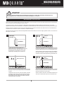
HINWEIS!
Bevor Sie mit der Installation des Soundsystems beginnen, trennen Sie unbedingt den Massepol der
Fahrzeugbatterie ab, um Kurzschlüsse und Stromschläge zu vermeiden.
MECHANISCHE INSTALLATION
Achten Sie bei der Installation darauf, dass keine serienmäßig im KFZ vorhandenen Teile wie z.B. Kabel, Bordcomputer, Sicherheitsgurte,
Tank oder ähnliche Teile beschädigt bzw.entfernt werden.
Vergewissern Sie sich, dass der Verstärker am Montageort genügend Kühlung erhält. Montieren Sie das Gerät nicht in zu kleine,
abgeschlossene Gehäuse ohne Luftzirkulation, in die Nähe von wärmeabstrahlende Teilen oder elektronischen Steuerungen des Fahrzeuges.
Montieren Sie den Verstärker auf keinen Fall auf ein Bassgehäuse oder andere vibrierende Teile, dadurch können sich die Bauteile im
Verstärkerinneren losvibrieren und den Verstärker ernsthaft beschädigen.
Die Kabel der Stromversorgung und die Audiosignalkabel sollten bei dem Einbau so kurz als möglich gehalten werden, um Verluste und
Störungen zu vermeiden.
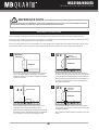
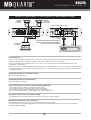
1
2
Montageöffnung
4x
Stift oder
Körner
Verstärker
Verstärker
Fahrzeug
An jeder Ecke des Geräts befinden sich
Montageöffnungen zur Befestigung am Fahrzeug.
Bitte achten Sie beim Montieren darauf, dass
die Oberfläche des Verstärkers nicht mit den
Werkzeugen beschädigt oder zerkratzt wird.
3
4x
Halten Sie den Verstärker an die gewünschte Einbaustelle
im Fahrzeug. Markieren Sie die vier Bohrlöcher mit einem
geeigneten Stift oder Körner durch die Montageöffnungen.
Achten Sie darauf, dass ausreichend Platz für die Installation
der Kabel vorhanden ist und diese nicht geknickt werden
sowie eine ausreichende Zugentlastung gewährleistet ist.
4
Bohrer (Ø 2 mm)
4x
Fixierschrauben
Verstärker
Markierung
Fahrzeug
Fahrzeug
Legen Sie dann den Verstärker beiseite und bohren dann
die Löcher für die Fixierschrauben an den zuvor markierten
Punkten.
Halten Sie dann den Verstärker wieder an die zuvor gewählte
Position und verschrauben den Verstärker mit den zuvor
gebohrten Bohrlöchern am Fahrzeug.
Vergewissern Sie sich zuvor, dass keine Kabel, Leitungen
und andere Komponenten des Fahrzeugs beim Bohren
beschädigt werden. Alternativ können Sie auch anstelle
eines Bohrers (je nach Untergrund) selbstschneidende
Gewindeschrauben verwenden.
Achten Sie darauf, dass der verschraubte Verstärker fest
sitzt und sich während der Fahrt nicht losvibrieren kann.
44
NSC2100/NSC475
INSTALLATIONSHINWEISE
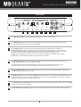
ELEKTRISCHE ANSCHLÜSSE
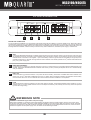
GND
REM
12V
R
FUSE
BRIDGED
L
POWER
PROTECT
POWER
1
INPUT
2
SPEAKER
3
OUTPUT
4
VOR DEM ANSCHLIESSEN
Für den fachgerechten Anschluss des Soundsystems sind geeignete Kabelsets im Fachhandel erhältlich. Achten Sie beim Kauf auf einen
ausreichenden Kabelquerschnitt (mind. 20 mm2), den passenden Sicherungswert sowie auf die Leitfähigkeit der Kabel. Säubern und
entfernen Sie vorhandene Rost- und Oxidationsstellen an allen Kontaktpunkten der Batterie und an den Massepunkten. Ziehen Sie nach
der Installation alle Schrauben fest an, denn ein lockerer Anschluss kann eine Fehlfunktion, unzureichende Stromversorgung oder
Störgeräusche sowie Verzerrungen zur Folge haben.
1
MASSEANSCHLUSS (GND)
Verbinden Sie die GND-Klemme des Verstärkers mit einem geeigneten Massepunkt am Fahrzeugchassis. Das Massekabel sollte
möglichst kurz sein und an einem blanken, metallischen Punkt des Fahrzeugchassis angebracht werden. Achten Sie darauf, dass
dieser Punkt eine sichere elektrische Verbindung zum Minuspol der Fahrzeugbatterie hat. Überprüfen Sie zudem die Masseleitung
von der Batterie zur Karosserie und verstärken diese wenn nötig. Verwenden Sie zum Anschluss ein ausreichend dimensioniertes
Massekabel (mind. 20 mm2). Der Querschnitt sollte dabei genauso groß wie bei der Plusleitung gewählt werde
2
EINSCHALTLEITUNG (REM)
Verbinden Sie den Schaltausgang (z.B. für automatische Antenne) oder die Steuerleitung (REM) des Steuergerätes (Autoradio)
mit dem Remote-Anschluss des Verstärkers. Für die Verbindung zwischen dem Remote-Anschluss des Verstärkers und dem
Steuergerät ist ein Kabel mit einem Querschnitt von 0.5 mm2 ausreichend. Dadurch schaltet sich der Verstärker beim Einschalten
des Autoradios automatisch mit ein oder wieder aus.
3
BATTERIEANSCHLUSS (BATT+12V)
Verbinden Sie diesen Schraubanschluss mit dem 12 Volt Pluspol der Fahrzeugbatterie. Verwenden Sie zum Anschluss ein
ausreichend dimensioniertes Stromkabel (mind. 20 mm2) und installieren Sie eine zusätzliche Kabelsicherung. Die Sicherung
sollte sich in Nähe der Batterie befinden, die Kabellänge vom Pluspol der Batterie bis zur Sicherung muss aus Sicherheitsgründen
unter 30 cm liegen. Die Sicherung setzen Sie erst nach Abschluss aller Installationsarbeiten ein.
4
GERÄTESICHERUNG (FUSE)
Die integrierten Stecksicherungen schützen das Gerät vor Kurzschlüssen und Überlastung. Die ab Werk installierte Sicherung
ist für den Anschluss an 4 Ohm Lautsprecher ausgelegt. Im 2 Ohm Betrieb erhöht sich die Stromaufnahme um ca. 50%, das heißt
die Gerätsicherungen müssen eventuell gegen entsprechend höhere Werte ausgetauscht werden.
HINWEIS!
Verlegen der Cinch/RCA Audiokabel und Stromversorgung
Bei der Installation des Audiokabels zwischen dem Cinch-Ausgang des Autoradios und dem Cinch-Eingang des Verstärkers im
Fahrzeug ist darauf zu achten, dass das Audio- und das Stromversorgungskabel möglichst nicht auf derselben Seite des Fahrzeugs
verlegt werden. Besser ist eine räumlich getrennte Installation, d.h. eine Installation des Stromkabels im linken Kabelschacht und
des Audiokabels im rechten Kabelschacht oder umgekehrt. Damit wird das Übersprechen von Störungen auf das Audio-Signal
verringert. Dieses gilt ebenfalls für das Verbindungskabel der Kabel-Fernbedienung, dieses Kabel sollte nicht auf der Seite der
Stromversorgungsleitung verlegt werden, sondern zusammen mit dem Audiokabel.
5
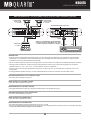
NSC2100
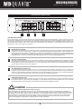
FUNKTIONEN UND BEDIENELEMENTE
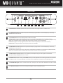
FRONTPANEL
BASS BOOST
LOW PASS
X-OVER
LP/BP
0dB 12dB
1
30Hz 250Hz
2
HIGH PASS
INPUT LEVEL
LINE INPUT
MODE
OUTPUT
L
L
R
R
FULL
HP
3
15Hz 250Hz
4
6V
5
0.2V
STEREO MONO
6
7
8
1
Der BASS BOOST-Regler regelt die Bassanhebung stufenlos von 0dB bis +12dB bei 45 Hz.
2
Der LOW PASS-Regler (Tiefpassfilter) bestimmt die Begrenzung des Frequenzgangs der Lautsprecher nach oben.
Die Trennfrequenz ist stufenlos von 30Hz bis 250Hz regelbar.
3
Der X-OVER-Schalter (Frequenzweichenschalter) selektiert die gewünschte Betriebsart des Verstärkers.
Position LP/BP: Tiefpass-Modus (Frequenz wird nach oben begrenzt, einstellbar über den LOW PASS - Regler)
Der HIGH PASS-Regler fungiert in dieser Betriebsart dann als Subsonicfilter und begrenzt die Frequenz nach unten
(Bandpass-Funktion). WICHTIG: Ist dieser höher als der LOW PASS eingestellt, kommt kein Ton.)
Position HP: Hochpass-Modus (Frequenz wird nach unten begrenzt, regelbar durch den HIGH PASS - Regler).
Position FULL: Vollbereich-Modus (gesamter Frequenzbereich wird verstärkt).
4
Der HIGH PASS-Regler (Hochpassfilter) bestimmt die Begrenzung des Frequenzgangs der Lautsprecher nach unten.
Die Trennfrequenz ist stufenlos von 15Hz bis 250Hz regelbar.
Im Tiefpass-Modus fungiert der HIGH PASS-Regler als Subsonicfilter und begrenzt die Frequenz nach unten
(Bandpass-Funktion). WICHTIG: Ist dieser höher als der LOW PASS eingestellt, kommt kein Ton.)
5
Der INPUT LEVEL-Regler bestimmt die Eingangsempfindlichkeit (Anpassung an das Ausgangssignal des Steuergeräts).
Der Regelbereich liegt zwischen 6 und 0.2 Volt.
6
Der MODE-Schalter bewirkt in Schalterstellung MONO, dass an LINE INPUT CH L nur ein Mono-Audiosignal mit einem CinchStecker angeschlossen werden muss. Diese Schalterstellung muss nur dann eingestellt werden, wenn mit dem Verstärker ein
Subwoofer (im Tiefpass-Modus LOW PASS) betrieben wird.
7
Die LINE INPUT Cinch-Audioeingänge müssen per Cinch-Kabel mit dem Steuergerät verbunden werden. Alle 2 Line-Eingänge
müssen im Stereo-Modus (# 6) belegt sein.
8
Die LINE OUTPUT-Cinchausgänge liefern ein lineares Vollbereichs-Audiosignal für die Ansteuerung weiterer Verstärker.
6
NSC2100
ANSCHLUSSBEISPIELE
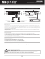
ANSCHLUSSBEISPIEL: 2-Kanal-Modus Stereo Front- oder Rearsystem
Schalterstellung STEREO
GND
REM
12V
FUSE
R
BRIDGED
L
BASS BOOST
LOW PASS
POWER
X-OVER
LP/BP
0dB 12dB
30Hz 250Hz
HIGH PASS
INPUT LEVEL
LINE INPUT
MODE
OUTPUT
L
L
R
R
FULL
HP
15Hz 250Hz
6V
0.2V
STEREO MONO
PROTECT
POWER
INPUT
SPEAKER
OUTPUT
Schalterstellung HP oder FULL
Stereo Cinch-Audiokabel (L/R) vom
Steuergerät mit dem LINE INPUT L/R
des Verstärkers verbinden
Lautsprecher links
2 – 8 Ohm
R
L
Lautsprecher rechts
2 – 8 Ohm
VERKABELUNG
• Verbinden Sie die Ausgänge des Steuergerätes (Radio) mit den Cinch-Eingängen (LINE INPUT) des Verstärkers mittels
• geeigneten hochwertigen Cinch-Audiokabeln.
• Verbinden Sie die Front- oder Rearlautsprecher mittels geeigneter Kabel mit den Lautsprecher-Ausgängen des Verstärkers • • •
(SPEAKER OUTPUT + 1CH - und + 2CH -).
• Achten Sie jedoch darauf, dass die Gesamtimpedanz aller Lautsprecher pro Kanal 2 Ohm nicht unterschreitet.
Zu niedrige Gesamtimpedanz resultiert in zu hoher Wärmeentwicklung und kann den Verstärker zum Abschalten bringen.
• Achten Sie stets auf korrekte Polung der Lautsprecher. Das Vertauschen von Plus und Minus hat einen Totalverlust der
Basswiedergabe zur Folge und kann unter Umständen die Lautsprecher beschädigen.
WEICHENKONFIGURATION
• Bei größeren Lautsprechersystemen (ab 20cm) können Sie die Vollbereichs-Stellung (FULL) am Schalter X-OVER wählen.
• Bei kleineren Lautsprechersystemen (8.7cm - 16cm) sollten Sie die Hochpass-Stellung (HP) am Schalter X-OVER wählen, damit die
Lautsprecher nicht durch zu tiefe Frequenzen beschädigt werden. Die Trennfrequenz sollte je nach Größe des Systems bei
ca. 60Hz - 150Hz liegen und ist über den HIGH PASS-Regler einstellbar.
• Der LOW PASS-Regler ist in diesem Anschlussbeispiel ohne Funktion.
PEGEL-REGLER
•
•
•
•
Drehen Sie den Regler INPUT LEVEL gegen den Uhrzeigersinn auf die 6 Volt Position.
Drehen Sie den Lautstärke-Regler des Steuergerätes auf 80% - 90% der maximalen Lautstärke.
Drehen Sie nun langsam den Regler INPUT LEVEL im Uhrzeigersinn, bis Sie aus den Lautsprechern leichte Verzerrungen hören.
Drehen Sie den Regler INPUT LEVEL nun ein Stück zurück, bis keine Verzerrungen mehr hörbar sind.
BASSANHEBUNG
• Den Regler BASS BOOST sollten Sie in diesem Anschlussbeispiel in die 0dB-Stellung bringen.
HINWEIS!
Verbinden Sie keine Lautsprecher-Kabel mit der Fahrzeugkarosserie. Achten Sie zudem stets auf die korrekte Polung der
Anschlüsse. Das Vertauschen von Plus und Minus hat einen Totalverlust der Basswiedergabe zur Folge und kann unter
Umständen die Lautsprecher beschädigen.
7
NSC2100
ANSCHLUSSBEISPIELE
ANSCHLUSSBEISPIEL: 1-Kanal-Modus Mono Subwoofer gebrückt
Schalterstellung MONO
GND
REM
12V
FUSE
R
BRIDGED
L
BASS BOOST
LOW PASS
POWER
X-OVER
LP/BP
0dB 12dB
30Hz 250Hz
HIGH PASS
INPUT LEVEL
LINE INPUT
MODE
OUTPUT
L
L
R
R
FULL
HP
15Hz 250Hz
6V
0.2V
STEREO MONO
PROTECT
POWER
INPUT
SPEAKER
OUTPUT
Schalterstellung LP/BP
Subwoofer
4 – 8 Ohm
Ein Mono Cinch-Audiokabel (L, R oder SUB OUT)
vom Steuergerät mit dem LINE INPUT L verbinden
L
VERKABELUNG
• Verbinden Sie den Ausgang des Steuergerätes (Radio) mit dem Cinch-Eingang (LINE INPUT CHL) des Verstärkers mittels
•
geeignetem hochwertigen Cinch-Audiokabel. Falls Ihr Steuergerät über einen separaten Subwoofer-Ausgang (SUB OUT) verfügt,
kann vorzugsweise dieser benutzt werden. Falls Ihr Steuergerät 2 Cinch-Ausgänge besitzt, verwenden Sie einen Y-Adpater.
• Verbinden Sie den Subwoofer mittels geeignetem Kabel mit den Lautsprecher-Ausgängen des Verstärkers
(SPEAKER OUTPUT + BRIDGED -).
• Achten Sie jedoch darauf, dass die Gesamtimpedanz des Kanalpaars 4 Ohm nicht unterschreitet.
Zu niedrige Gesamtimpedanz resultiert in zu hoher Wärmeentwicklung und kann den Verstärker zum Abschalten bringen.
• Achten Sie stets auf korrekte Polung der Lautsprecher. Das Vertauschen von Plus und Minus hat einen Totalverlust der
Basswiedergabe zur Folge und kann unter Umständen die Lautsprecher beschädigen.
WEICHENKONFIGURATION
• Im Mono-/Subwoofer-Betrieb müssen Sie die Tiefpass-Stellung (LP/BP) wählen, dadurch wird der Subwoofer von den höheren
• Frequenzen abgetrennt. Die Trennfrequenz sollte je nach Größe des Subwoofers bei 60Hz - 100Hz liegen und ist über den
• LOW PASS-Regler einstellbar.
• In der Tiefpass-Stellung (LP/BP) ist gleichzeitig der Hochpass-Regler (HIGH PASS) als Subsonic-Filter aktiv, dadurch werden die
• ultratiefen nicht hörbaren aber teilweise für den Subwoofer schädlichen Frequenzen vom Signal herausgefiltert und ein
BANDPASS-Signal erzeugt. Die Subsonicfrequenz sollte je nach Größe des Subwoofers bei 15Hz - 40Hz liegen.
WICHTIG: Ist dieser höher als der LOW PASS eingestellt, kommt kein Ton.
PEGEL-REGLER
•
•
•
•
Drehen Sie den Regler INPUT LEVEL gegen den Uhrzeigersinn auf die 6 Volt Position.
Drehen Sie den Lautstärke-Regler des Steuergerätes auf 80% - 90% der maximalen Lautstärke.
Drehen Sie nun langsam den Regler INPUT LEVEL im Uhrzeigersinn, bis Sie aus den Lautsprechern leichte Verzerrungen hören.
Drehen Sie den Regler INPUT LEVEL nun ein Stück zurück, bis keine Verzerrungen mehr hörbar sind.
BASSANHEBUNG
• Der Regler BASS BOOST erlaubt eine Bassanhebung um bis zu +12dB.
• Eine zu hoch eingestellte Bassanhebung kann Ihre Lautsprecher durch Clipping/Überlastung zerstören sowie Ihr Hörvermögen nachhaltig
schädigen. Benutzen Sie diesen Regler stets mit Bedacht.
HINWEIS!
Verbinden Sie keine Lautsprecherleitungen mit der Fahrzeugkarosserie.
Achten Sie zudem stets auf die korrekte Polung der Anschlüsse.
Benutzen Sie die Bassanhebung stets mit Bedacht. Eine zu hoch eingestellte Bassanhebung kann Ihre Lautsprecher durch
Clipping/Überlastung zerstören und Ihr Hörvermögen nachhaltig schädigen.
8
NSC475
FUNKTIONEN UND BEDIENELEMENTE
FRONTPANEL
BASS BOOST
LOW PASS
CH1/CH2
X-OVER
HIGH PASS
INPUT LEVEL CH1
LINE INPUT
CH3
OUTPUT
R
0dB
12dB
BASS BOOST
0dB
12dB
30Hz
150Hz
LOW PASS
30Hz
LP/BP
HP
FULL
HIGH PASS
X-OVER
150Hz LP/BP HP
10Hz 150Hz
FULL
10Hz 150Hz
6V
0.2V
6V
0.2V
INPUT LEVEL
CH3/CH4
1
2
3
L
CH2
4
5
CH4
6
7
1
Die BASS BOOST-Regler CH1/2 & CH3/4 regeln jeweils die Bassanhebung des Kanalpaars von 0dB bis +12dB bei 45 Hz.
2
Die LOW PASS-Regler CH1/2 & CH3/4 (Tiefpassfilter) bestimmen jeweils die Begrenzung des Frequenzgangs der Lautsprecher
des Kanalpaars nach oben. Die Trennfrequenz ist stufenlos von 30Hz bis 150Hz regelbar.
3
Die X-OVER-Schalter CH1/2 & CH3/4 (Frequenzweichenschalter) selektieren die gewünschte Betriebsart des Kanalpaars.
Position LP/BP: Tiefpass-Modus (Frequenz wird nach oben begrenzt, einstellbar über den LOW PASS - Regler)
Der HIGH PASS-Regler fungiert in dieser Betriebsart dann als Subsonicfilter und begrenzt die Frequenz nach unten
(Bandpass-Funktion). WICHTIG: Ist dieser höher als der LOW PASS eingestellt, kommt kein Ton.)
Position HP: Hochpass-Modus (Frequenz wird nach unten begrenzt, regelbar durch den HIGH PASS - Regler).
Position FULL: Vollbereich-Modus (gesamter Frequenzbereich wird verstärkt).
4
Die HIGH PASS-Regler CH1/2 & CH3/4 (Hochpassfilter) bestimmen jeweils die Begrenzung des Frequenzgangs der Lautsprecher
des Kanalpaars nach unten. Die Trennfrequenz ist stufenlos von 10Hz bis 150Hz regelbar.
Im Tiefpass-Modus fungiert der HIGH PASS-Regler als Subsonicfilter und begrenzt die Frequenz nach unten
(Bandpass-Funktion). WICHTIG: Ist dieser höher als der LOW PASS eingestellt, kommt kein Ton.)
5
Die INPUT LEVEL-Regler CH1/2 & CH3/4 bestimmen pro Kanalpaar die Eingangsempfindlichkeit (Anpassung an das Ausgangssignal
des Steuergeräts). Der Regelbereich liegt zwischen 6 und 0.2 Volt.
6
Die LINE INPUT Cinch-Audioeingänge müssen per Cinch-Kabel mit dem Steuergerät verbunden werden. Alle 4 Line-Eingänge
müssen belegt sein. Falls nur ein Stereo-Signal mit 2 Steckern zur Verfügung steht, müssen Sie zwei Cinch Y-Adapter zum
Aufsplitten des Signals verwenden.
7
Die LINE OUTPUT-Cinchausgänge liefern ein lineares Vollbereichs-Audiosignal für die Ansteuerung weiterer Verstärker.
9
NSC475
ANSCHLUSSBEISPIELE
ANSCHLUSSBEISPIEL: 4-Kanal-Modus Stereo Front- und Hecksystem
Lautsprecher
vorne / links
2 – 8 Ohm
Lautsprecher
vorne / rechts
2 – 8 Ohm
Stereo Cinch-Audiokabel (FL/FR & RL/RR)
vom Steuergerät mit LINE INPUT CH1 / CH2
und CH3 / CH4 des Verstärkers verbinden
Schalterstellung HP oder FULL
GND
REM
12V
FUSE
CH1
BRIDGED
CH2
CH3
BRIDGED
CH4
BASS BOOST
LOW PASS
CH1/CH2
X-OVER
HIGH PASS
INPUT LEVEL CH1
LINE INPUT
CH3
OUTPUT
R
POWER
0dB
12dB
BASS BOOST
30Hz
150Hz
LOW PASS
LP/BP
HP
FULL
10Hz 150Hz
HIGH PASS
X-OVER
6V
0.2V
6V
0.2V
INPUT LEVEL
PROTECT
0dB
POWER
INPUT
12dB
30Hz
150Hz LP/BP HP
FULL
10Hz 150Hz
CH3/CH4
SPEAKER OUTPUT
L
CH2
CH4
Schalterstellung
HP oder FULL
Lautsprecher
hinten / links
2 – 8 Ohm
Lautsprecher
hinten / rechts
2 – 8 Ohm
FL
FR
RR
RL
VERKABELUNG
• Verbinden Sie die Ausgänge des Steuergerätes (Radio) mit den Cinch-Eingängen (LINE INPUT) des Verstärkers mittels
geeigneten hochwertigen Cinch-Audiokabeln.
• Falls nur ein Stereo-Signal mit 2 Steckern zur Verfügung steht, müssen Sie zwei Cinch Y-Adapter zum Aufsplitten des Signals verwenden.
• Verbinden Sie die Front- und Hecklautsprecher mittels geeignetem Kabel mit den Lautsprecher-Ausgängen des Verstärkers
• (SPEAKER OUTPUT + 1CH - und + 2CH - und + 3CH - und + 4CH -).
• Achten Sie jedoch darauf, dass die Gesamtimpedanz aller Lautsprecher pro Kanal 2 Ohm nicht unterschreitet.
• Zu niedrige Gesamtimpedanz resultiert in zu hoher Wärmeentwicklung und kann den Verstärker zum Abschalten bringen.
WEICHENKONFIGURATION CH1/2 & CH3/4
• Bei größeren Lautsprechersystemen (ab 20cm) können Sie die Vollbereichs-Stellung (FULL) wählen.
• Bei kleineren Lautsprechersystemen (8.7cm - 16cm) sollten Sie die Hochpass-Stellung (HP) wählen, damit die Lautsprecher nicht durch
zu tiefe Frequenzen zerstört werden. Die Trennfrequenz sollte bei 60Hz - 150Hz, je nach Größe des Systems liegen und ist über den
HIGH PASS-Regler einstellbar. Der LOW PASS-Regler ist in dieser Konfiguration ohne Funktion.
PEGEL-REGLER CH1/2 & CH3/4
•
•
•
•
Drehen Sie den Regler INPUT LEVEL gegen den Uhrzeigersinn auf die 6 Volt Position.
Drehen Sie den Lautstärke-Regler des Steuergerätes auf 80% - 90% der maximalen Lautstärke.
Drehen Sie nun langsam den Regler INPUT LEVEL im Uhrzeigersinn, bis Sie aus den Lautsprechern leichte Verzerrungen hören.
Drehen Sie den Regler INPUT LEVEL nun ein Stück zurück, bis keine Verzerrungen mehr hörbar sind.
BASSANHEBUNG
• Den Regler BASS BOOST sollten Sie in diesem Anschlussbeispiel in die 0dB-Stellung bringen.
HINWEIS!
Verbinden Sie keine Lautsprecher-Kabel mit der Fahrzeugkarosserie. Achten Sie zudem stets auf die korrekte Polung der
Anschlüsse. Das Vertauschen von Plus und Minus hat einen Totalverlust der Basswiedergabe zur Folge und kann unter
Umständen die Lautsprecher beschädigen.
10
NSC475
ANSCHLUSSBEISPIELE
ANSCHLUSSBEISPIEL: 2-Kanal-Modus Mono 2 Subwoofer gebrückt
Subwoofer 1
4 – 8 Ohm
Schalterstellung LP/BP
GND
REM
12V
FUSE
CH1
BRIDGED
CH2
CH3
BRIDGED
CH4
BASS BOOST
LOW PASS
CH1/CH2
X-OVER
HIGH PASS
LINE INPUT
CH3
INPUT LEVEL CH1
OUTPUT
R
POWER
0dB
12dB
BASS BOOST
30Hz
150Hz
LOW PASS
LP/BP
HP
FULL
10Hz 150Hz
HIGH PASS
X-OVER
6V
0.2V
6V
0.2V
INPUT LEVEL
PROTECT
0dB
POWER
INPUT
Subwoofer 2
4 – 8 Ohm
12dB
30Hz
150Hz LP/BP HP
FULL
10Hz 150Hz
CH3/CH4
SPEAKER OUTPUT
L
CH2
CH4
Schalterstellung
LP/BP
Stereo Cinch-Audiokabel (L/R oder SUB OUT)
vom Steuergerät mittels zwei Cinch
Y-Adaptern mit den LINE INPUTS verbinden
Y-Adapter
L
R
VERKABELUNG
• Verbinden Sie die Ausgänge des Steuergerätes (Radio) mit den Cinch-Eingängen des Verstärkers. Es müssen alle 4 LINE INPUTS
(CH1/CH2/CH3/CH4) belegt werden. Dafür benötigen Sie zwei Cinch Y-Adapter zum Aufsplitten des Signals. Falls Ihr Steuergerät über
einen separaten Subwoofer-Ausgang (SUB OUT) verfügt, kann vorzugsweise dieser benutzt werden.
• Verbinden Sie die beiden Subwoofer mittels geeignetem Kabel mit den Lautsprecher-Ausgängen des Verstärkers (SPEAKER
• OUTPUT CH1/2 + BRIDGED - und CH3/4 + BRIDGED -).
• Achten Sie jedoch darauf, dass die Gesamtimpedanz aller Subwoofer pro Kanalpaar 4 Ohm nicht unterschreitet.
• Zu niedrige Gesamtimpedanz resultiert in zu hoher Wärmeentwicklung und kann den Verstärker zum Abschalten bringen.
• Achten Sie stets auf korrekte Polung der Lautsprecher. Das Vertauschen von Plus und Minus hat einen Totalverlust der
Basswiedergabe zur Folge und kann unter Umständen die Lautsprecher beschädigen.
WEICHENKONFIGURATION CH1/2 & CH3/4 (SUBWOOFER 1 & SUBWOOFER 2)
• Im Mono-/Subwoofer-Betrieb müssen Sie die Tiefpass-Stellung (LP/BP) wählen, dadurch wird der Subwoofer von den höheren
• Frequenzen abgetrennt. Die Trennfrequenz sollte je nach Größe des Subwoofers bei 60Hz - 100Hz liegen und ist über den
• LOW PASS-Regler einstellbar.
• In der Tiefpass-Stellung (LP/BP) ist gleichzeitig der Hochpass-Regler (HIGH PASS) als Subsonic-Filter aktiv, dadurch werden die
• ultratiefen nicht hörbaren aber teilweise für den Subwoofer schädlichen Frequenzen vom Signal herausgefiltert und ein
BANDPASS-Signal erzeugt. Die Subsonicfrequenz sollte je nach Größe des Subwoofers bei 15Hz - 40Hz liegen.
WICHTIG: Ist dieser höher als der LOW PASS eingestellt, kommt kein Ton.
PEGEL-REGLER CH1/2 & CH3/4 (SUBWOOFER 1 & SUBWOOFER 2)
•
•
•
•
Drehen Sie den Regler INPUT LEVEL gegen den Uhrzeigersinn auf die 6 Volt Position.
Drehen Sie den Lautstärke-Regler des Steuergerätes auf 80% - 90% der maximalen Lautstärke.
Drehen Sie nun langsam den Regler INPUT LEVEL im Uhrzeigersinn, bis Sie aus den Lautsprechern leichte Verzerrungen hören.
Drehen Sie den Regler INPUT LEVEL nun ein Stück zurück, bis keine Verzerrungen mehr hörbar sind.
BASSANHEBUNG CH1/2 & CH3/4 (SUBWOOFER 1 & SUBWOOFER 2)
• Der Regler BASS BOOST erlaubt eine Bassanhebung um bis zu +12dB.
• Eine zu hoch eingestellte Bassanhebung kann Ihre Lautsprecher durch Clipping/Überlastung zerstören sowie Ihr Hörvermögen nachhaltig
schädigen. Benutzen Sie diesen Regler stets mit Bedacht.
11
NSC475
ANSCHLUSSBEISPIELE
ANSCHLUSSBEISPIEL: 3-Kanal-Modus Stereo System & Mono Subwoofer gebrückt
Lautsprecher
vorne / links
2 – 8 Ohm
Lautsprecher
vorne / rechts
2 – 8 Ohm
Schalterstellung HP oder FULL
GND
REM
12V
FUSE
CH1
BRIDGED
CH2
CH3
BRIDGED
CH4
BASS BOOST
LOW PASS
CH1/CH2
X-OVER
HIGH PASS
INPUT LEVEL CH1
LINE INPUT
CH3
OUTPUT
R
POWER
0dB
12dB
BASS BOOST
30Hz
150Hz
LOW PASS
LP/BP
HP
FULL
10Hz 150Hz
HIGH PASS
X-OVER
6V
0.2V
6V
0.2V
INPUT LEVEL
PROTECT
0dB
POWER
INPUT
12dB
30Hz
150Hz LP/BP HP
FULL
10Hz 150Hz
CH3/CH4
SPEAKER OUTPUT
L
CH2
CH4
Schalterstellung
LP/BP
Subwoofer
4 – 8 Ohm
Stereo Cinch-Audiokabel (FL/FR & RL/RR)
vom Steuergerät mit LINE INPUT CH1 / CH2
und CH3 / CH4 des Verstärkers verbinden
FL
FR
RR
RL
VERKABELUNG
• Verbinden Sie die Ausgänge des Steuergerätes (Radio) mit den Cincheingängen (LINE INPUT) des Verstärkers mittels geeigneten
hochwertigen Cinch-Audiokabeln. Falls Ihr Steuergerät über einen separaten Subwoofer-Ausgang (SUB OUT) verfügt kann dieser
vorzugsweise für CH3/4 (Subwooferkanal) benutzt werden.
• Falls nur ein Stereo-Signal mit 2 Steckern zur Verfügung steht, müssen Sie zwei Cinch Y-Adapter zum Aufsplitten des Signals verwenden
• Verbinden Sie die Lautsprecher und den Subwoofer mittels geeignetem Kabel mit den Lautsprecher-Ausgängen des Verstärkers
• (SPEAKER OUTPUT + CH 1 - und + CH 2 - und den Subwoofer mit CH3/4 + BRIDGED -).
• Achten Sie darauf, dass die Gesamtimpedanz pro Kanal (CH1 & CH2) 2 Ohm bzw. pro Kanalpaar (CH 3/4 gebrückt) 4 Ohm nicht
unterschreitet.
• Zu niedrige Gesamtimpedanz resultiert in zu hoher Wärmeentwicklung und kann den Verstärker zum Abschalten bringen.
WEICHENKONFIGURATION CH1/2 (STEREO SYSTEM)
• Siehe dazu die Einstellungen auf Seite 10.
PEGEL-REGLER CH1/2 (STEREO SYSTEM)
• Siehe dazu die Einstellungen auf Seite 10.
BASSANHEBUNG CH1/2 (STEREO SYSTEM)
• Den Regler BASS BOOST sollten Sie in diesem Anschlussbeispiel in die 0dB-Stellung bringen.
WEICHENKONFIGURATION CH3/4 (SUBWOOFER )
• Siehe dazu die Einstellungen auf Seite 11.
PEGEL-REGLER CH3/4 (SUBWOOFER )
• Siehe dazu die Einstellungen auf Seite 11.
BASSANHEBUNG CH3/4 (SUBWOOFER )
• Der Regler BASS BOOST erlaubt eine Bassanhebung um bis zu +12dB.
• Eine zu hoch eingestellte Bassanhebung kann Ihre Lautsprecher durch Clipping/Überlastung zerstören sowie Ihr Hörvermögen nachhaltig
schädigen. Benutzen Sie diesen Regler stets mit Bedacht.
12
NSC2100/NSC475
NOTIZEN
1133
NSC2100/NSC475
TECHNISCHE DATEN
MODELLE
NSC2100
NSC475
KANÄLE
SCHALTUNGSPRINZIP
2
CLASS A/B
Analog
4
CLASS A/B
Analog
AUSGANGSLEISTUNG RMS 13,8 V
Watt an 4 Ohm
Watt an 2 Ohm
Watt an 4 Ohm mono gebrückt
2 x 100
2 x 175
1 x 350
4 x 75
4 x 125
2 x 250
AUSGANGSLEISTUNG MAX. 13,8 V
Watt an 4 Ohm
Watt an 2 Ohm
Watt an 4 Ohm mono gebrückt
2 x 300
2 x 350
1 x 700
4 x 150
4 x 250
2 x 500
Frequenzgang
Dämpfungsfaktor
Signal-Rauschabstand
Kanaltrennung
Klirrfaktor (THD&N)
Eingangsempfindlichkeit
Eingangsimpedanz
10Hz - 50 kHz
>200
>104 dB
74 dB
<0,05%
6 - 0.2 V
47 kOhm
10Hz - 50 kHz
>200
>104 dB
74 dB
<0,05%
6 - 0.2 V
47 kOhm
CH 1 & CH 2
Weichenmodus
Variable Hochpassweiche
Variable Tiefpassweiche
Bassanhebung @ 45 Hz
LP/BP - HP - Full
15 - 250 Hz
30 - 250 Hz
0 - 12 dB
LP/BP - HP - Full
10 - 150 Hz
30 - 150 Hz
0 - 12 dB
CH 3 & CH 4
Weichenmodus
Variable Hochpassweiche
Variable Tiefpassweiche
Bassanhebung @ 45 Hz
–
–
–
–
LP/BP - HP - Full
10 - 150 Hz
30 - 150 Hz
0 - 12 dB
Cinch/RCA Signal-Ausgänge
Vollbereich
Vollbereich
Sicherungswert
2 x 25 A
2 x 30 A
Abmessungen
Breite & Höhe
Länge
205 x 50 mm
275 mm
205 x 50 mm
275 mm
Technische Änderungen und Irrtümer vorbehalten!
Für Schäden am Fahrzeug oder Gerätedefekte, hervorgerufen durch Bedienungsfehler des Geräts, können wir keine Haftung
übernehmen.
Alle MB QUART Verstärker sind mit einer individuellen Seriennummer versehen, die für statistische und servicebedingte Zwecke
aufgezeichnet wird.
Alle MB QUART Verstärker sind sowohl mit einer E-Kennzeichnung als auch einer CE-Kennzeichnung versehen. Damit sind die
Geräte für den Betrieb in Fahrzeugen innerhalb der Europäischen Union (EU) zertifiziert.
GARANTIEHINWEIS
Die Garantieleistung entspricht der gesetzlichen Regelung. Von der Garantieleistung ausgeschlossen sind Defekte und Schäden,
die durch Überlastung, unsachgemäße Behandlung oder durch die Teilnahme an Wettbewerben entstanden sind. Retournieren
Sie das defekte Produkt nur mit einem gültigen Kaufbeleg und einer detaillierten Fehlerbeschreibung.
14
NSC2100/NSC475
FEHLERBEHEBUNG
STATUS LEDs & SCHUTZSCHALTUNG
GND
Die STATUS LEDs befinden sich neben den Stromanschlüssen und
sind mit PROTECT und POWER gekennzeichnet.
REM
FUSE
12V
POWER
1. Leuchtet die POWER LED weiß ist der Verstärker betriebsbereit.
2. Leuchtet die PROTECT LED in rot, liegt eine Fehlfunktion vor.
Beachten Sie dann die folgenden Hinweise im Abschnitt
FEHLERBEHBUNG
PROTECT
POWER
INPUT
HINWEIS!
SCHUTZSCHALTUNG
Im Verstärker sind verschiedene elektronische Schutzsicherungen integriert. Bei Überlastung, Überhitzung, Kurzschluss
an den Lautsprechern, aber auch bei zu niederohmigen Betrieb oder mangelhafter Stromversorgung schaltet dieser
ab, um größeren Schäden vorzubeugen. Liegt eine der oben genannten Störungen vor, beginnt die PROTECT LED
rot zu leuchten.
Prüfen Sie in diesem Fall alle Anschlüsse auf Fehler, wie. z.B. Kurzschlüsse, fehlerhafte Verbindungen oder Überhitzung.
Gehen sie dabei wie auf der vorangegangenen Seite vor.
Wenn die Störung (z.B. Überhitzung) beseitigt wurde, kann der Verstärker wieder in Betrieb genommen werden.
Hört die PROTECT LED nicht auf rot zu leuchten, liegt ein Defekt am Verstärker vor. In diesem Fall bitten wir Sie, das
Gerät mit einer detaillierten Fehlerbeschreibung und einer Kopie des Kaufbeleges an Ihren Fachhändler zu retournieren.
ACHTUNG: Öffnen Sie keinesfalls den Verstärker und versuchen diesen selbst zu reparieren, dies hat einen
Garantieverlust zur Folge. Diese Reparaturmaßnahmen sollten nur von geschulten Technikern durchgeführt werden.
HINWEIS!
STÖRUNGEN / INTERFERENZEN
Die Ursache von Interferenzen sind meist immer die verlegten Kabel. Besonders anfällig dafür sind die Strom- und
Cinchkabel des Sound Systems. Oftmals werden Interferenzen durch Generatoren (Lichtmaschine) oder andere
elektronische Steuergeräte des KFZ (Benzinpumpe, Klimaanlage etc.) verursacht. Die meisten dieser Probleme können
durch korrektes und sorgfältiges Verkabeln vermieden werden.
Hier finden Sie dazu einige Hilfestellungen:
1. Benutzen Sie nur mehrfach abgeschirmte hochwertige Cinch Audiokabel für die Anschlüsse zwischen Verstärker
und Steuergerät. Eine brauchbare Alternative sind im Zubehörhandel erhältliche Entstörmaßnahmen.Verwenden
Sie möglichst keine Entstörfilter, welche die Masse am Cinch/RCA-Audiokabel auftrennen.
2. Verlegen Sie die Signal-, Lautsprecher- und Stromkabel seperat mit ausreichendem Abstand zueinander und ebenso
zu jedem anderen Kabel im Fahrzeug. Benutzen Sie dazu die verschiedenen Kabelkanäle des Fahrzeugs. Sollte
diese nicht möglich sein, können Sie das Stromkabel zusammen mit den seriellen Kabeln im Fahrzeug verlegen.
Die Cinch Audiokabel sollten soweit wie möglich von diesen entfernt liegen. Das Kabel der Einschaltleitung des
Steuergeräts (Remote) kann zusammen mit dem Cinch Audiokabel verlegt werden.
3. Vermeiden Sie Masse-Schleifen indem Sie die Masse-Verbindungen aller Komponenten in einer sternförmigen
Anordnung verlegen. Den geeigneten Masse-Mittelpunkt können Sie durch Messen der Spannung direkt an der
Batterie ermitteln. Messen Sie mit einem Multi-Meter die Spannung der Fahrzeug-Batterie. Sie sollten diese Messung
bei eingeschalteter Zündung und angeschalteten Verbrauchern (z.B. Licht, Heckscheibenheizung) durchführen.
Diesen Wert müssen Sie dann mit dem von Ihnen gewählten Masse-Punkt und dem Plus-Terminal (+12V) des
Verstärkers vergleichen. Wenn die gemessenen Spannungen nur geringfügig voneinander abweichen, haben Sie
den richtigen Masse-Punkt gefunden. Andernfalls müssen Sie einen anderen Punkt wählen.
4. Benutzen Sie möglichst Kabel mit angesetzten oder verlöteten Kabelschuhen oder dergleichen. Vergoldete oder
hochwertig vernickelte Kabelschuhe sind korrosionsfrei und haben einen geringeren Kontakt-Widerstand.
15
SP
NSC2100/NSC475
FEHLERBEHEBUNG
Fehler: keine Funktion
Ursache:
Lösung:
1. Die Stromversorgungskabel sind nicht korrekt angeschlossen.
Erneute Überprüfung
2. Die Kabel haben keinen elektrischen und mechanischen Kontakt.
Erneute Überprüfung
3. Die Remote-Steuerleitung des Steuergeräts (Autoradio) ist nicht korrekt am Verstärker angeschlossen.
Erneute Überprüfung
4. Sicherungen defekt. Im Falle des Austauschs achten Sie bitte auf den korrekten Wert der Sicherungen.
Sicherungen austauschen
Fehler: kein Ton aus Lautsprecher, aber POWER leuchtet weiß
Ursache:
Lösung:
1. Die Lautsprecherkabel oder Cinchkabel sind nicht korrekt angeschlossen.
Erneute Überprüfung
2. Die Lautsprecherkabel oder Cinchkabel sind defekt.
Kabel ersetzen
3. Die Lautsprecher sind defekt.
Lautsprecher ersetzen
4. High Pass Regler (Subsonic Modus) in Betriebsart LP/BP zu hoch eingestellt.
Regler runterdrehen
5. Kein Signal vom Steuergerät (Radio).
Steuergerät-Einstellungen prüfen
Fehler: Ein bzw. mehrere Kanäle/Regler ohne Funktion / fehlerhaftes Stereobild
Ursache:
Lösung:
1. Der Balance- bzw. Fader-Regler am Steuergerät ist nicht in der Mittel-Position.
Auf Nullwert stellen
2. Ein Kabel an Lautsprecher oder Verstärker hat sich gelöst.
Erneute Überprüfung
3. Die Lautsprecher sind defekt.
Lautsprecher ersetzen
4. High Pass Regler in Betriebsart LP/BP zu hoch eingestellt.
Regler runterdrehen
Fehler: Verzerrungen aus Lautsprecher
Ursache:
Lösung:
1. Die Lautsprecher sind überlastet.
Pegel niedriger einstellen
Pegel am Steuergerät niedriger einstellen
Loudness am Steuergerät abschalten
Bass EQ am Steuergerät neu einstellen
Fehler: Keine Bässe bzw. kein Stereo-Sound
Ursache:
Lösung:
1. Beim Anschluss sind an den Lautsprechern bzw. Kabeln plus (+) und minus (-) vertauscht worden.
Erneuter korrekter Anschluss
2. Die Cinchkabel sind lose, falsch angeschlossen oder beschädigt/defekt.
Erneuter korrekter Anschluss oder ersetzen
Fehler: Verstärker schaltet in den Schutz-Modus (PROTECT leuchtet rot)
Ursache:
Lösung:
1. Kurzschluss an den Lautsprechern bzw. Kabeln.
Erneuter korrekter Anschluss
2. Überhitzung durch zu niedrige Impedanz der Lautsprecher.
Andere höhere Impedanz wählen
Neue Lautsprecheranordnung wählen
3. Mangelnde Luftzufuhr durch ungünstigen Einbauort des Verstärkers.
Anderer Einbauort wählen
Für Luftzufuhr sorgen
4. Überlastung durch Strommangel (zu dünne Kabelquerschnitte bei den Stromkabeln).
Größerer Kabelquerschnitt installieren
Fehler: Rauschen aus den Lautsprechern
Ursache:
Lösung:
1. Die Pegel-Regler am Verstärker sind voll aufgedreht.
Pegel niedriger einstellen
2. Der Hochton-Regler am Steuergerät ist voll aufgedreht.
Pegel am Steuergerät niedriger einstellen
3. Die Lautsprecherkabel oder Cinchkabel sind defekt oder beschädigt.
Kabel ersetzen
4. Das Rauschen kommt vom Steuergerät.
Steuergerät überprüfen lassen
16
NSC2100/NSC475
TABLE OF CONTENT
SAFETY INSTRUCTIONS
18
INSTALLATION INSTRUCTIONS
19
2-CHANNEL AMPLIFIERS
21
Functions and controls
21
Interconnection example 2-Channel-Mode: 1 x Stereo System (Front or Rear)
22
Interconnection example 1-Channel-Mode: 1 x Mono Subwoofer bridged
23
4-CHANNEL AMPLIFIERS
24
Features and operational controls
24
Interconnection example 4-Channel-Mode: 1 x Stereo System (Front) and 1 x Stereo System (Rear)
25
Interconnection example 2-Channel-Mode: 2 x Mono Subwoofer bridged
26
Interconnection example 3-Channel-Mode: 1 x Stereo System and 1 x Mono Subwoofer bridged
27
SPECIFICATIONS
29
TROUBLE SHOOTING
30
REFERENCE NOTE!
VERY IMPORTANT ADVICE FOR THE INSTALLATION AND OPERATION IN NEWER VEHICLES!
In vehicles with a newer year of manufacturing (since approx. 2002), normally computer controlled diagnosis- and controlling systems
are applied - like CAN-BUS or MOST-BUS interfaces. By the installation of a car audio amplifier a new appliance will be added to
the 12V on-board electrical system, which may cause under several circumstances error messages or may interrupt this factory
made diagnosis system, as a result of high stress peaks and a higher power consumption. Thus to this, depending on model and
manufacturer, the driving safety or important security systems like airbags, ESC or others could be interrupted.
If you plan to operate the amplifier in a vehicle like described above, please follow these instructions:
• Admit the installation only by a skilled specialist, best by a service company, which is specialized on
maintenance and reparing your vehicle and which is familiar with the electrical on-board system of the vehicle.
• After the installation, order by any means a computer based diagnosis of the on-board system by your service company
to detect possible malfunctions or error messages.
• If the on-board system is interrupted by the installation of the amplifier, in-between installed power capacitors can
stabilize the electrical on-board system and ensure a proper and stable operation.
• The best solution is the integration of an additional second 12 V electrical system for the complete sound system, which
can be operated independently via a own battery supply.
CONSULT BY ANY MEANS YOUR CAR SPECIALIZED SERVICE COMPANY!
PLEASE KEEP THIS MANUAL FOR LATER PURPOSES!
17
NSC2100/NSC475
SAFETY INSTRUCTIONS
PLEASE OBSERVE THE FOLLOWING ADVICES BEFORE THE FIRST OPERATION!
DO NOT INSTALL THE DEVICE AT LOCATIONS, WHERE IT
WILL BE EXPOSED TO HIGH HUMIDITY AND DUST. Install
the device at a location, where it will be protected from high
humidity and dust. If humidity and dust attain inside the device,
malfunctions may be caused.
THE PURCHASED DEVICE IS ONLY SUITABLE FOR AN OPERATION WITH A 12V ON-BOARD ELECTRICAL SYSTEM OF A
VEHICLE. Otherwise fire hazard, risk of injury and electric shock
consists.
PLEASE DO NOT MAKE ANY OPERATION OF THE SOUNDSYSTEM, WHICH DISTRACT YOU FROM A SAFE DRIVING.
Do not make any procedures, which demand a longer attention.
Perform these operations not until you have stopped the vehicle
on a safe place. Otherwise the risk of accident consists.
MOUNT THE DEVICE AND OTHER COMPONENTS OF THE
SOUND SYSTEM SUFFICIENTLY. Otherwise the device and
components may get loose and act as dangerous objects, which
could cause serious harm and damages in the passenger room.
ADJUST THE SOUND VOLUME TO AN APPROPRIATE LEVEL,
THAT YOU ARE STILL ABLE TO HEAR EXTERIOR NOISES
WHILE DRIVING. High performance sound systems in vehicles
may generate the acoustic pressure of a live concert. The permanent listening to extrem loud music may cause the loss of your
hearing abilities. The hearing of extreme loud music while driving
may derogate your cognition of warning signals in the traffic. In
the interests of the common safeness, we suggest to drive with
a lower sound volume. Otherwise the risk of accident consists.
ENSURE NOT TO DAMAGE COMPONENTS, WIRES AND
CABLES OF THE VEHICLE WHEN YOU DRILL THE MOUNTING
HOLES. If you drill the mounting holes for the installation into the
vehicle’s chasis, ensure by any means, not to damage, block or
tangent the fuel pipe, the gas tank, other wires or electrical cables.
DO NOT COVER COOLING VENTS AND HEATSINKS. Otherwise
this may cause heat accumulation in the device and fire hazard
consists.
DO NOT INSTALL AUDIO CABLES AND POWER SUPPLY
WIRES TOGETHER. Observe while installation not to lead the
audio cables between the headunit and the amplifier together with
the power supply wires on the same side of the vehicle. The best
is a areal separated installation in the left and right cable channel
of the vehicle. Therewith a overlap of interferences on the audio
signal will be avoided. This stands also for the equipped bassremote wire, which should be installed not together with the power
supply wires, but rather with the audio signal cables.
ENSURE CORRECT CONNECTION OF ALL TERMINALS. Faulty
connections may could cause fire hazard and lead to damages
of the device.
DO NOT OPEN THE DEVICE. Otherwise fire hazard, risk of injury
and electric shock consists. Also this may cause a loss of the
warranty.
REPLACE FUSES ONLY WITH FUSE WITH THE SAME RATING. Otherwise fire hazard and risk of electric shock consists.
ENSURE THAT CABLES MAY NOT CAUGHT UP IN CLOSEBY OBJECTS. Install all the wires and cables like described on
the following pages, therewith these may not hinder the driver.
Cables and wires which are installed close-by the steering wheel,
gear lever or the brake pedal, may caught up and cause highly
dangerous situations.
DO NOT USE THE DEVICE ANY LONGER, IF A MALFUNCTION,
WHICH REMAINS UNREMEDIED. Observe in this case the
section TROUBLE SHOOTING. Otherwise risk of injury and the
damage of the device consists. Commit the device to an authorized
retailer.
THE INSTALLATION OF A POWER CAPACITOR WITH SUFFICIENT CAPACITY IS RECOMMENDED. High performance
amplifiers cause high potential voltage drops and need a high
power consumption at a high volume level. To relieve the vehicle’s
on-board system, it is recommended to install a power capacitor
between the battery and the device which works as buffer. Consult
your car audio retailer for the appropriate capacity.
DO NOT SPLICE ELECTRICAL WIRES. The electrical wires
should not be bared, to provide power supply to other devices.
Otherwise the load capacity of the wire may get overloaded. Use
therefor a appropriate distribution block. Otherwise fire hazard
and risk of electric shock consists.
DO NOT USE BOLTS AND SCREW NUTS OF THE BRAKE
SYSTEM AS GROUND POINT. Never use for the installation or
the ground point bolts and screw-nuts of the brake system, steering
system or other security-relevant components. Otherwise fire
hazard consists or the driving safety will be derogated.
INTERCONNECTION AND INSTALLATION SHOULD BE ACCOMPLISHED BY SKILLED STAFF ONLY. The interconnection
and installation of this device demands technical aptitude and
experience. For your own safness, commit the interconnexion
and installation to your car audio retailer, where you have purchased
the device.
ENSURE NOT TO BEND OR SQUEEZE CABLES AND WIRES
BY SHARP OBJECTS. Do not install cables and wires not closeby movable objects like the seat rail or may be bended or harmed
by sharp and barbed edges. If you lead a wire or cable through
the hole in a metal sheet, protect the insulation with a rubber
grommet.
DISCONNECT THE GROUND CONNECTION FROM THE
VEHICLE’S BATTERY BEFORE INSTALLATION. Before you
start with the installation of the sound system, disconnect by any
means the ground supply wire from the battery, to avoid any risk
of electric shock and short circuits.
KEEP AWAY SMALL PARTS AND JACKS FROM CHILDREN.
If objects like these will be swallowed, a risk of serious injuries
consists. Consult promtly a medical doctor, if a child swallowed
a small object.
CHOOSE A APPROPRIATE LOCATION FOR THE INSTALLATION OF THE DEVICE. Look for a appropriate location for the
device, which ensures a sufficient air circulation. The best places
are spare wheel cavities, and open spaces in the trunk area. Less
suitable are storage spaces behind the side coverings or under
the car seats.
18
NSC2100/NSC475
INSTALLATION INSTRUCTIONS
REFERENCE NOTE
Before you start with the installation of the sound system, disconnect by any means the GROUND connection
wire from the battery, to avoid any risk of electric shock and short circuits.
MECHANICAL INSTALLATION
Avoid any damage removing of the components of the vehicle like wires, cables, board computer, seat belts, gastank or the like.
Ensure that chosen location provide sufficient air circulation for the amplifier. Do not mount the device into small or sealed spaces without
air circulation near by heat dispersing parts or electrical parts of the vehicle.
Do not mount the amplifier on top of a subwooferbox or any other vibrating parts, thereby parts in the inside of the amplifier may get loosen.
The wires and cables of power supply and the audio signal must be as short as possible, to avoid any losses and interferences.
1
2
Mounting
opening
4x
Pen or
peening tool
Amplifier
Amplifier
Vehicle
The mounting openings for the installation are located on
each corner of the amplifier. Please ensure during the
installation, that you don’t scratch or damage the amplifier
surface with the tools.
Uphold the amplifier to the chosen mounting location in
the vehicle. Then mark the four drill holes with a appropriate
pen or peening tool and lead through the mounting openings.
Observe that enough space remains for the installation of
the cables and ensure that they will not be bended and
have sufficient pull relief.
3
4x
4
Drill (Ø 2 mm)
4x
Mounting
screws
Amplifier
Marking
Vehicle
Vehicle
Put the amplifier aside and then drill the holes for the
mounting screws at the before marked locations.
Then uphold the amplifier to the chosen position and fix
the screws through the holes of the mounting brackets into
the drilled screwholes.
Please ensure not to damage any components of the vehicle
while drilling the holes. Alternatively (depends on the material
of the surface) you can also use self-tapping screws.
Ensure that the mounted amplifier is fixed tight and not get
loosen.
19
NSC2100/NSC475
INSTALLATION INSTRUCTIONS
ELECTRICAL INTERCONNECTION
GND
REM
12V
R
FUSE
BRIDGED
L
POWER
PROTECT
POWER
1
INPUT
2
SPEAKER
3
OUTPUT
4
BEFORE THE CONNECTION
For the professional installation of a sound system appropriate wiring kits are available in car audio retailer stores. Attend the sufficient
profile section (at least 20 mm2), the suitable fuse rating and the conductivity of the cables when you purchase your wiring kit. Clean and
remove rust-streaked and oxidized areas on the contact points of the battery and the ground connection. Make sure that all screws are
fixed tight after the installation, because loosely connections may cause malfunctions, unsufficient power supply or interferences.
1
GND
Connect this GROUND terminal with a suitable contact ground point on the vehicle’s chassis. The ground wire must be as short
as possible and must be connected to a blank metallic point at the vehicle’s chassis. Ensure that this ground point has a stable
and safe electric connection to the negative “–”pole of the battery. Check this ground wire from the battery to the ground point if
possible and enforce it, if required. Use a ground wire with a sufficient cross section (at least 20 mm2) and the same size like the
plus (+12V) power supply wire.
2
REM (TURN-ON SIGNAL)
Connect the turn-on signal (e.g. automatic antenna) or the turn-on remote signal of your headunit with the REM-terminal of the
amplifier. Use therefor a suitable cable with a sufficient cross section (0,5 mm2). Thereby the amplifier will turn on or off automatically
with your headunit.
3
BATT+12V
Connect the BATT+12V-terminal with the +12V pole of the vehicle’s battery. Use therefor a suitable cable with a sufficient cross
section (min. 20 mm2) and install a additional in-line fuse. For safety reasons the distance between the fuseblock and the battery
must be shorter than 30 cm. Do not install the fuse into the fuseblock until the installation is accomplished.
4
FUSE
The inserted fuses protect the amplifier from shorts and capacity overload. The equipped standard fuse is suitable for a 4 ohm
speaker load. For a 2 ohm speaker load the current consumption increases by 50%, thereby the fuses may need to be replaced
by fuses with a higer rating.
REFERENCE NOTE
Installation of RCA/Audio signal cables and power supply.
Attend while installation not to lead the audio cables between the headunit and the amplifier together with the power supply wires
on the same side of the vehicle. The best is a areal separated installation in the left and right cable channel of the vehicle. Therewith
a overlap of interferences on the audio signal will be avoided. This stands also for the equipped bass-remote wire, which should be
installed not together with the power supply wires, but rather with the audio signal cables.
20
NSC2100
FUNCTIONS AND OPERATIONAL CONTROLS
FRONT PANEL
BASS BOOST
LOW PASS
X-OVER
LP/BP
0dB 12dB
1
30Hz 250Hz
2
HIGH PASS
INPUT LEVEL
LINE INPUT
MODE
OUTPUT
L
L
R
R
FULL
HP
3
15Hz 250Hz
4
6V
5
0.2V
STEREO MONO
6
7
8
1
The BASS BOOST controller adjusts the bass boost enhancement continuously from 0dB to +12dB at 45 Hz.
2
The LOW PASS controller adjusts the cut-off point of the frequency range to above. The cut-off frequency is continuously
adjustable from 30 Hz to 250 Hz.
3
The X-OVER switch selects the required operation mode of the amplifier.
Position LP/BP: Lowpass mode (the higher frequencies will be eliminated. Adjustable by the LOW PASS controller.)
The HIGH PASS controller works in this operation mode as subsonicfilter and eliminates the lower frequencies (Bandpass-Mode).
NOTE: If this controller is turned to a higher value than the lowpass controller, no sound is hearable.
Position HP: Highpass mode (the higher frequencies will be eliminate. Adjustable by the HIGH PASS controller.)
Position FULL: Fullrange mode (the entire frequency range will be amplified).
4
The HIGH PASS controller adjusts the cut-off point of the frequency range to below. The cut-off frequency is continuously
adjustable from 15 Hz to 250 Hz.
The HIGH PASS controller works in the LP/BP mode as subsonicfilter and eliminates the lower frequencies (Bandpass-Mode).
NOTE: If this controller is turned to a higher value than the lowpass controller, no sound is hearable.
5
The INPUT LEVEL controller adjusts the input sensitivity of the amplifier to align the audio signal from the head unit.
The input sensitivity is adjustable from 6 to 0.2 Volts.
6
The MODE switch enables in switch position MONO, that only one RCA jack with a mono audio signal needs to be connected
on LINE INPUT CH L. Chose this mode only, if you want to run the amplifier with a subwoofer in the LOW PASS mode.
7
The LINE INPUT RCA jacks must be connected with the RCA output jacks of the headunit. All 2 LINE INPUTS must be connected.
8
The LINE OUT RCA jacks provide a linear fullrange audiosignal to supply an additional amplifier.
21
NSC2100
INTERCONNECTION EXAMPLES
INTERCONNECTION EXAMPLE 2-Channel Mode: 1x Stereo System (Front or rear)
Switch position STEREO
GND
REM
12V
FUSE
R
BRIDGED
L
BASS BOOST
LOW PASS
POWER
X-OVER
LP/BP
0dB 12dB
30Hz 250Hz
HIGH PASS
INPUT LEVEL
LINE INPUT
MODE
OUTPUT
L
L
R
R
FULL
HP
15Hz 250Hz
6V
0.2V
STEREO MONO
PROTECT
POWER
INPUT
SPEAKER
OUTPUT
Switch position HP or FULL
Connect stereo RCA output
(L/R) of the headunit with
LINE INPUT L/R of the amplifier
Loudspeaker left
2 – 8 Ohms
R
L
Loudspeaker right
2 – 8 Ohms
INTERCONNECTION
• Connect the RCA lineouts of the headunit with the RCA jacks LINE INPUT of the amplifier with appropriate high-value RCA cables.
• Connect the front- or rear speakers with the speaker outputs (SPEAKER OUTPUT + 1CH - and + 2CH -) by using appropriate wires.
• Ensure by any means, that the total impedance load of all speakers is not lower than 2 ohms. Too low impedance cause high temperature
and will shut down the amplifier operation.
• Always ensure the correct polarity of the speakers. The interchange of plus and minus cause total loss of bass playback and could
damage the speakers.
CROSSOVER SETTINGS
• For bigger speakers (more than 20cm) you can set the X-OVER switch to the FULL position (Full Range Signal).
• For smaller speakers (8.7cm - 16cm) you must set the X-OVER switch to the HP Position (Highpass Mode) to avoid any damage
by lower frequencies on the speakers. The cut-off frequency is adjustable with the HIGH PASS controller and should be set between
60Hz to 150Hz, depending on the size of the speakers.
• The LOW PASS Controller is not in use in this interconnecting example.
LEVEL INPUT CONTROLLER
• Turn the INPUT LEVEL controller of the amplifier to the 6V position.
• Turn the volume controller of the headunit to 80 - 90% of its full setting.
• Turn the INPUT LEVEL controller clockwise until you hear some distortion.
• Then turn back the INPUT LEVEL controller slightly until you hear a cleaner sound.
BASS BOOST CONTROLLER
• The BASS BOOST controller must be turned to 0 dB position in this interconnecting example .
REFERENCE NOTE
Do not connect loudspeaker cables with the vehicle chassis. Always ensure the correct polarity of all connections.
The interchange of plus and minus cause total loss of bass playback and could damage the speakers.
22
NSC2100
INTERCONNECTION EXAMPLES
INTERCONNECTION EXAMPLE 1-Channel Mode: 1x Mono Subwoofer bridged
Switch position MONO
GND
REM
12V
FUSE
R
BRIDGED
L
BASS BOOST
LOW PASS
POWER
X-OVER
LP/BP
0dB 12dB
30Hz 250Hz
HIGH PASS
INPUT LEVEL
LINE INPUT
MODE
OUTPUT
L
L
R
R
FULL
HP
15Hz 250Hz
6V
0.2V
STEREO MONO
PROTECT
POWER
INPUT
SPEAKER
OUTPUT
Switch position LP/BP
Connect one mono RCA output (L, R or SUB OUT)
of the headunit with LINE INPUT L of the amplifier
L
Subwoofer
4 – 8 Ohms
INTERCONNECTION
• Connect the RCA lineout of the headunit with the RCA jack LINE INPUT CH L of the amplifier with an appropriate high-value RCA
cable. If your headunit is equipped with a additional subwoofer lineout (SUB OUT), it is recommended to use this lineout.
• Connect the subwoofer with the speaker outputs (SPEAKER OUTPUT + BRIDGED -) by using appropriate wires.
• Ensure by any means, that the total impedance load of the channel-pair is not lower than 4 ohms. Too low impedance cause high
temperature and will shut down the amplifier operation.
• Always ensure the correct polarity of the speakers. The interchange of plus and minus cause total loss of bass playback and could
damage the speakers.
CROSSOVER SETTINGS
• In the mono/subwoofer mode the X-OVER switch must set to the LP/BP position (Lowpass/Bandpass mode), thereby the higher
frequencies will be eliminated. The cut-off frequency ist adjustable with the LOW PASS controller and should be set between
60 to 100 Hz, depending on the size of the subwoofer.
• In the lowpass mode (LP/BP) the HIGH PASS controller works also as subsonicfilter, that eliminates the ultra-low, not hearable and
harmful frequencies to generate a bandpass signal (Bandpass mode). The subsonic frequency should be set between 15 to 40 Hz,
depending on the size of the subwoofer. NOTE: If this value is higher than the lowpass setting, no sound is hearable.
LEVEL CONTROLLER
• Turn the INPUT LEVEL controller of the amplifier to the 6V position.
• Turn the volume controller of the headunit to 80 - 90% of its full setting.
• Turn the INPUT LEVEL controller clockwise until you hear some distortion.
• Then turn back the INPUT LEVEL controller slightly until you hear a cleaner sound.
BASS BOOST CONTROLLER
• The BASS BOOST controller adjusts the bass enhancement between 0db and +12dB.
• A too high bass boost may cause clipping/distortion and damage on the loudspeakers and also may harm your hearing abilities.
Use this controller carefully!
REFERENCE NOTE
Do not connect loudspeaker cables with the vehicle chassis. Always ensure the correct polarity of all connections.
Use the bass enhancement with care. A high bass boost may cause damage to your speakers and hearing abilities.
23
NSC475
FUNCTIONS AND CONTROLS
FRONT PANEL
BASS BOOST
LOW PASS
CH1/CH2
X-OVER
HIGH PASS
INPUT LEVEL CH1
LINE INPUT
CH3
OUTPUT
R
0dB
12dB
BASS BOOST
0dB
12dB
30Hz
150Hz
LOW PASS
30Hz
LP/BP
HP
FULL
HIGH PASS
X-OVER
150Hz LP/BP HP
10Hz 150Hz
FULL
10Hz 150Hz
6V
0.2V
6V
0.2V
INPUT LEVEL
CH3/CH4
1
2
3
L
CH2
4
5
CH4
6
7
1
The BASS BOOST CH1/2 and CH3/4 controllers adjust the bass boost enhancement continuously from 0dB to +12dB at
45 Hz for the regarding channel pair (Channel 1/2 or Channel 3/4).
2
The LOW PASS CH1/2 and CH3/4 controllers adjust the cut-off point of the frequency range to above for the regarding channel
pair (Channel 1/2 or Channel 3/4). The cut-off frequency is continuously adjustable from 30 Hz to 150 Hz.
3
The CH1/2 and CH3/4 X-OVER switch selects the required operation mode of the amplifier on the regarding channel pair (Channel
1/2 or Channel 3/4).
Position LP/BP: Lowpass mode (The higher frequencies will be eliminated. Adjustable by the lowpass controller.)
The HIGH PASS controller works in this operation mode as subsonicfilter and eliminates the lower frequencies (Bandpass-Mode).
NOTE: If this controller is turned to a higher value than the lowpass controller, no sound is hearable.
Position HP: Highpass mode (The higher frequencies will be eliminated. Adjustable by the highpass controller.)
Position FULL: Fullrange mode (The whole frequencies will be amplified).
4
The HIGH PASS CH1/2 and CH3/4 controllers adjust the cut-off point of the frequency range to below for the regarding channel
pair (Channel 1/2 or Channel 3/4). The cut-off frequency is continuously adjustable from 10 Hz to 150 Hz.
The HIGH PASS controller works in the LP/BP mode as subsonicfilter and eliminates the lower frequencies (Bandpass-Mode).
NOTE: If this controller is turned to a higher value than the lowpass controller, no sound is hearable.
5
The LEVEL INPUT CH1/2 and CH3/4 controllers adjust the input sensitivity of the amplifier to align the audio signal of the head
unit for the regarding channel pair (Channel 1/2 or Channel 3/4). The input sensitivity is adjustable from 6 to 0.2 Volts.
6
The LINE INPUT RCA jacks must be connected with the RCA output jacks of the headunit. All 4 LINE INPUTS must be connected.
If there is only one stereo signal with two jacks available, you must use two Y-connectors to splice the signal.
7
The LINE OUT RCA jacks provide a linear fullrange audiosignal to supply an additional amplifier.
24
NSC475
INTERCONNECTION EXAMPLES
INTERCONNECTION EXAMPLE 4-Channel Mode: 2 x Stereo System (Front & Rear)
Loudspeaker
front / left
2 – 8 Ohms
Loudspeaker
front / right
2 – 8 Ohms
Connect the stereo RCA output (FL/FR and
RL/RR) of the headunit with LINE INPUTS
CH1/2 and CH3/4 of the amplifier
Switch position HP or FULL
GND
REM
12V
FUSE
CH1
BRIDGED
CH2
CH3
BRIDGED
CH4
BASS BOOST
LOW PASS
CH1/CH2
X-OVER
HIGH PASS
INPUT LEVEL CH1
LINE INPUT
CH3
OUTPUT
R
POWER
0dB
12dB
BASS BOOST
30Hz
150Hz
LP/BP
LOW PASS
HP
FULL
10Hz 150Hz
HIGH PASS
X-OVER
6V
0.2V
6V
0.2V
INPUT LEVEL
PROTECT
0dB
POWER
INPUT
12dB
30Hz
150Hz LP/BP HP
FULL
10Hz 150Hz
CH3/CH4
SPEAKER OUTPUT
L
CH2
CH4
Switch position
HP or FULL
Loudspeaker
rear / left
2 – 8 Ohms
Loudspeaker
rear / right
2 – 8 Ohms
FL
FR
RR
RL
INTERCONNECTION
• Connect the RCA lineouts of the headunit with the RCA jacks LINE INPUT of the amplifier with appropriate high-value RCA cables.
• If there is only one stereo signal with two jacks available, you must use two y-connectors to splice the signal.
• Connect the front- and rear speakers with the speaker outputs (SPEAKER OUTPUT + 1CH -, + 2CH - and + 3CH -, + 4CH -).
• Ensure by any means, that the total impedance load of all speakers is not lower than 2 ohms per channel.
Too low impedance cause high temperature and will shut down the amplifier operation.
• Always ensure the correct polarity of the speakers. The interchange of plus and minus cause total loss of bass playback and could
damage the speakers.
CROSSOVER SETTINGS CH1/2 & CH3/4
• For bigger speakers (more than 20cm) you can set the X-OVER switch to the FULL position (Full Range Signal).
• For smaller speakers (8.7cm - 16cm) you must set the X-OVER switch to the HP Position (Highpass Mode) to avoid any damage
by lower frequencies on the speakers. The cut-off frequency is adjustable with the HIGH PASS controller and should be set between
60Hz to 150Hz, depending on the size of the speakers.
• The LOW PASS Controller is not in use in this interconnecting example.
LEVEL INPUT CONTROLLER CH1/2 & CH3/4
• Turn the INPUT LEVEL controller of the amplifier to the 6V position.
• Turn the volume controller of the headunit to 80 - 90% of its full setting.
• Turn the INPUT LEVEL controller clockwise until you hear some distortion.
• Then turn back the INPUT LEVEL controller slightly until you hear a cleaner sound.
BASS BOOST CONTROLLER
• The BASS BOOST controller must be turned to 0 dB position in this interconnecting example .
REFERENCE NOTE
Do not connect loudspeaker cables with the vehicle’s chassis. Always ensure the correct polarity of all connections. The
interchange of plus and minus cause total loss of bass playback and could damage the speakers.
25
NSC475
INTERCONNECTION EXAMPLES
INTERCONNECTION EXAMPLE 2-Channel Mode: 2 x Mono Subwoofer bridged
Subwoofer 1
4 – 8 Ohms
Switch position LP/BP
GND
REM
12V
FUSE
CH1
BRIDGED
CH2
CH3
BRIDGED
CH4
BASS BOOST
LOW PASS
CH1/CH2
X-OVER
HIGH PASS
LINE INPUT
CH3
INPUT LEVEL CH1
OUTPUT
R
POWER
0dB
12dB
BASS BOOST
30Hz
150Hz
LOW PASS
LP/BP
HP
FULL
10Hz 150Hz
HIGH PASS
X-OVER
6V
0.2V
6V
0.2V
INPUT LEVEL
PROTECT
0dB
POWER
INPUT
Subwoofer 2
4 – 8 Ohms
12dB
30Hz
150Hz LP/BP HP
FULL
10Hz 150Hz
CH3/CH4
SPEAKER OUTPUT
L
CH2
CH4
Switch position
LP/BP
Connect Stereo RCA output (L/R or SUB OUT)
of the headunit with the LINE INPUT L/R of
the amplifier by using two Y-connectors
Y-Connectors
L
R
INTERCONNECTION
• Connect the RCA lineouts of the headunit with the RCA jacks LINE INPUT. All LINE INPUT jacks must be connected (CH1/CH2/CH3/CH4).
Therefor you need to use two Y-connectors to splice the audio signal. If a separate SUB OUT from your headunit is available, use this
as LINE OUT.
• Connect the subwoofers with the SPEAKER OUTPUTS CH1/2 + BRIDGED - and CH3/4 + BRIDGED -.
• Ensure by any means, that the total impedance load of all subwoofers per channelpair is not lower than 4 ohms. Too low impedance
cause high temperature and will shut down the amplifier operation.
• Always ensure the correct polarity of the speakers. The interchange of plus and minus cause total loss of bass playback and could
damage the speakers.
CROSSOVER SETTINGS CH1/2 & CH3/4 (SUBWOOFER 1 & SUBWOOFER 2)
• In the mono/subwoofer mode the X-OVER switch must set to the LP/BP position (Lowpass/Bandpass mode), thereby the higher
frequencies will be eliminated. The cut-off frequency ist adjustable with the LOW PASS controller and should be set between
60 to 100 Hz, depending on the size of the subwoofer.
• In the lowpass mode (LP/BP) the HIGH PASS controller works also as subsonicfilter, that eliminates the ultra-low, not hearable and
harmful frequencies to generate a bandpass signal (Bandpass mode). The subsonic frequency should be set between 15 to 40 Hz,
depending on the size of the subwoofer. NOTE: If this value is higher than the lowpass setting, no sound is hearable.
LEVEL CONTROLLER CH1/2 & CH3/4 (SUBWOOFER 1 & SUBWOOFER 2)
• Turn the INPUT LEVEL controller of the amplifier to the 6V position.
• Turn the volume controller of the headunit to 80 - 90% of its full setting.
• Turn the INPUT LEVEL controller clockwise until you hear some distortion.
• Then turn back the INPUT LEVEL controller slightly until you hear a cleaner sound.
BASS BOOST CONTROLLER CH1/2 & CH3/4 (SUBWOOFER 1 & SUBWOOFER 2)
• The BASS BOOST controller adjusts the bass enhancement between 0db and +12dB.
• A too high bass boost may cause clipping/distortion and damage on the loudspeakers and also may harm your hearing abilities.
Use this controller carefully!
26
NSC475
INTERCONNECTION EXAMPLES
EXAMPLE 3-Channel Mode: 1 x Stereo System & 1 x Mono Subwoofer bridged
Speaker
front/left
2 – 8 Ohms
Speaker
front/right
2 – 8 Ohms
Switch position HP or FULL
GND
REM
12V
FUSE
CH1
BRIDGED
CH2
CH3
BRIDGED
CH4
BASS BOOST
LOW PASS
CH1/CH2
X-OVER
HIGH PASS
INPUT LEVEL CH1
LINE INPUT
CH3
OUTPUT
R
POWER
0dB
12dB
BASS BOOST
30Hz
150Hz
LP/BP
LOW PASS
HP
FULL
10Hz 150Hz
HIGH PASS
X-OVER
6V
0.2V
6V
0.2V
INPUT LEVEL
PROTECT
0dB
POWER
INPUT
12dB
30Hz
150Hz LP/BP HP
FULL
10Hz 150Hz
CH3/CH4
SPEAKER OUTPUT
L
CH2
CH4
Switch position
LP/BP
Subwoofer
4 – 8 Ohms
Connect the stereo RCA output (FL/FR and
RL/RR) of the headunit with LINE INPUTS
CH1/2 and CH3/4 of the amplifier
FL
FR
RR
RL
INTERCONNECTION
• Connect the RCA lineouts of the headunit with the RCA jacks LINE INPUT of the amplifier with appropriate high-value RCA cables. If a
separate SUB OUT from your headunit is available, use this for the LINE INPUT CH3/4 on the amplifier.
• Connect the speakers with SPEAKER OUTPUT + CH 1 - and + CH 2 - and the subwoofer with the SPEAKER OUTPUT CH3/4
+ BRIDGED - of the amplifier.
• Ensure by any means, that the total impedance load of all speakers per channelpair (CH1 & CH2) is not lower than 2 ohms and the total
impedance load of the subwoofer (CH3 & CH4) is not lower than 4 ohms. Too low impedance cause high temperature and will shut down
the amplifier operation.
CROSSOVER SETTINGS CH1/2 (STEREO-SYSTEM)
• Observe the settings on page 25.
CROSSOVER SETTINGS CH3/4 (SUBWOOFER)
• Observe the settings on page 26.
LEVEL CONTROLLER CH1/2 & CH3/4 (STEREO SYSTEM & SUBWOOFER)
• Turn the INPUT LEVEL controller of the amplifier to the 6V position.
• Turn the volume controller of the headunit to 80 - 90% of its full setting.
• Turn the INPUT LEVEL controller clockwise until you hear some distortion.
• Then turn back the INPUT LEVEL controller slightly until you hear a cleaner sound.
BASS BOOST CONTROLLER CH1/2 (STEREO-SYSTEM)
• The BASS BOOST controller must be turned to 0 dB position in this interconnecting example .
BASS BOOST CONTROLLER CH3/4 (SUBWOOFER)
• The BASS BOOST controller adjusts the bass enhancement between 0db and +12dB.
• A too high bass boost may cause clipping/distortion and damage on the loudspeakers and also may harm your hearing abilities.
Use this controller carefully!
27
NSC2100/NSC475
NOTES
1283
NSC2100/NSC475
SPECIFICATIONS
MODELS
NSC2100
NSC475
CHANNELS
CIRCUIT
2
CLASS A/B
Analog
4
CLASS A/B
Analog
OUTPUTPOWER RMS 13,8 V
Watts @ 4 Ohms
Watts @ 2 Ohms
Watts @ 4 Ohm mono bridged
2 x 100
2 x 175
1 x 350
4 x 75
4 x 125
2 x 250
OUTPUTPOWER MAX. 13,8 V
Watts @ 4 Ohms
Watts @ 2 Ohms
Watts @ 4 Ohm mono bridged
2 x 200
2 x 350
1 x 700
4 x 150
4 x 250
2 x 500
Frequency Range –3dB
Damping Factor
Signal-to-Noise Ratio
Channel Separation
THD&N
Input Sensitivity
Input Impedance
10Hz - 50 kHz
>300
>104 dB
74 dB
<0,05%
6 - 0.2 V
47 kOhms
10Hz - 50 kHz
>200
>104 dB
74 dB
<0,05%
6 - 0.2 V
47 kOhms
CH 1 & CH 2
X-Over Modes
Various Highpassfilter
Various Lowpassfilter
Bass Boost @ 45 Hz
LP/BP - HP - Full
15 - 250 Hz
30 - 250 Hz
0 - 12 dB
LP/BP - HP - Full
10 - 150 Hz
30 - 150 Hz
0 - 12 dB
CH 3 & CH 4
X-Over Modes
Various Highpassfilter
Various Lowpassfilter
Bass Boost @ 45 Hz
–
–
–
–
LP/BP - HP - Full
10 - 150 Hz
30 - 150 Hz
0 - 12 dB
Cinch/RCA Outputs
Fullrange
Fullrange
Fuse Ratings
2 x 25 A
2 x 30 A
Dimensions
Width & Height
Length
205 x 50 mm
275 mm
205 x 50 mm
275 mm
Technical specifications are subject to change! Errors are reserved!
For damages on the vehicle and the device, caused by handling errors of the device, we can’t assume liability.
All MB Quart Amplifiers are tagged with a individual serialnumber, which will be registerd for statistic and service conditional
purposes.
All MB Quart Amplifiers are tagged with a E-Certification Number and also a CE-Certification Mark. Thereby these devices are
ceritified for the use inside vehicles inside the European Union (EU).
WARRANTY DISCLAIMER
The limited warranty comply with legal regulations. Failures or damages caused by overload, improper use or by using the
product for competitions are not covered by the warranty.
Please return the defective product only with a valid proof of purchase and a detailed malfunction description.
29
NSC2100/NSC475
TROUBLE SHOOTING
STATUS LEDs & PROTECTION CIRCUIT
GND
The STATUS LED are located next to the power supply terminals and marked
as POWER and PROTECT.
REM
POWER
1. If the POWER LED lights up in white, the amplifier is turned on and
is ready for operation.
2. If the PROTECT LED lights up in red, a malfunction occurs on the
amplifier. Please observe in this case the following information in the
section TROUBLE SHOOTING.
POWER
FUSE
12V
PROTECT
INPUT
REFERENCE NOTE
PROTECTION CIRCUIT
This amplifier owns a 3-way protection circuit. If overloading, overheating and shorted loudspeakers, or too low
impedance or insufficient power supply is insisted, the amplifier shuts down to prevent serious damage. If one of this
disfunctions is detected, the PROTECT LED lights up.
Check in this case all connections to detect short-circuits, faulty connections or overheating. Attend the regarding notes
on the previous page.
If the reason for the disfunction is eliminated, the amplifier is ready for operation again.
If the PROTECT LED still lights up in red, a damage on the amplifier is insisted. In this case return the amplifier to
your car audio retailer with a detailled malfunction description and a copy of the proof of purchase.
WARNING: Never open the amplifier and try to repair it by yourself. This causes a loss of warranty. The repairing
service should be made only by skilled technicians.
REFERENCE NOTE
ELECTRICAL INTERFERENCES
The reason for interferences are mostly the passed cables and wires. Especially the power and audio cables (RCA)
of your sound system are vulnerable. Often these interferences are caused by electric generators or other electrical
units (fuel pump, AC etc.) of the car. The most of these problems can be prevented by a correct and careful wiring.
Here are some courtesy notes:
1. Use only double or triple shielded audio RCA cables for the connection between the amplifier and headunit. A useful
alternative are represented by anti-noise-devices or additional ancillary equipment like Balanced Line Transimtters,
which you can purchase at your car audio retailer. If possible do not use anti-noise-filters, which are splicing the
ground of the RCA audio cables.
2. Do not lead the audio cables between the headunit and the amplifier together with the power supply wires on the
same side of the vehicle. The best is a areal separated installation in the left and right cable channel of the vehicle.
Therewith a overlap of interferences on the audio signal will be avoided. This stands also for the equipped bassremote wire, which should be installed not together with the power supply wires, but rather with the audio signal
cables.
3. Avoid ground loops by connecting all ground connections in a starlike arrangement. The suitable ground center
point is ascertainable by measuring of the voltage directly on the vehicle’s battery by a multi-meter. You should
measure the voltage with turned-on inginition (acc.) and with other turned-on power consumers (e.g. headlights, rear
window defroster, etc).Compare the measured value with the voltage of the ground point you have chosen for the
installation and the positive pole (+12V) of the amplifier. If the voltage has just a little difference, you have found a
suitable ground point. Otherwise you need to choose another ground point.
4. Use if possible only cables with added or soldered cable sockets or the like. Gold plated or high value nickel plated
cable sockets are corrosionfree and own a very low contact resistance.
30
SPE
NSC2100/NSC475
TROUBLE SHOOTING
Malfunction: no function
Reason:
Remedy:
1. The power supply connection of the device is not correct.
Recheck
2. The cabels have no mechanical or electrical contact.
Recheck
3. The remote turn-on connection from the headunit to the amplifier is not correct.
Recheck
4. Defective Fuses. In case of replacing the fuses, attend by any means the correct fuse rating.
Replace Fuses
Malfunction: no signal on loudspeakers, but POWER LED lights up white
Reason:
Remedy:
1. The connection of the speakers or the RCA audio cables is not correct..
Recheck
2. The speaker cables or the RCA audio cables are defective.
Replace cables
3. The loudspeakers are defective.
Replace speakers
4. High pass controller (Subsonic Mode) in LP/BP operation is adjusted to high.
Turn down controller
5. No signal from headunit.
Check headunit settings
Malfunction: one or more channels/controllers are without function / faulty stereo stage
Reason:
Remedy:
1. The balance or fader controller of the headunit is not in the zero-position.
Turn to zero-position
2. The connection of the speakers is not correct.
Recheck
3. The loudspeakers are defective.
Replace speakers
4. High pass controller in LP/BP operation is adjusted to high.
Turn down controller
Malfunction: distortions on the loudspeaker’s signal
Reason:
Remedy:
1. The loudspeakers are overloaded.
Turn down the level
Turn down the level on the headunit
Switch off loudness on the headunit
Reset bass EQ on the headunit
Malfunction: No bass or stereo sound
Reason:
Remedy:
1. Interchange of loudspeaker cable polarity positive (+) and negative (-).
Reconnect
2. The RCA audio cables are loose or defective.
Reconnect or replacing the cables
Malfunction: amplifier runs into protection mode (PROTECT LED lights up red)
Reason:
Remedy:
1. Short circuit on the loudspeakers or cables.
Reconnect
2. Overheated by too low speaker impedance.
Choose a higher impedance
Use a new speaker setup
3. Insufficient air circulation by a inappropriate mounting position of the amplifier.
Change the mounting position
Ensure air circulation
4. Overloaded by insufficient power supply (too thin profile section on the power cables).
Use a bigger profile section
Malfunction: hiss or white noise on the loudspeaker’s signal
Reason:
Remedy:
1. The level controllers are turned up.
Turn down the level
2. The treble controller on the headunit is turned up.
Turn down the level on the headunit
3. The speaker cables or the RCA audio cables are defective.
Replacing the cables
4. The hissing is caused by the headunit.
Check the headunit
31