1
Omslag 99-06-02 19.48 Sidan 1
AXIS 2400 Video Server Administration Manual
AXIS 2400 Video Server Administration Manual
Part No: 16644
Revision 1.0, Date: March 1999
Copyright © Axis Communications AB, 1999
AXIS Video Servers
(
The Plug-and-Watch Remote Monitoring and
Surveillance Solution for TCP/IP Networks
Axis Communications
http://www.axis.com
Lund
Phone: +46 46 270 18 00
Boston
Phone: +1-800-444-AXIS
Miami
Phone: +1 305 266 1633
Paris
Phone: +33 1 49 69 15 50
Munich
Phone: +49 89 95 93 96 0
London
Phone: +44 171 553 9200
Tokyo
Phone: +81 3 3545 8282
Singapore
Phone: +65 250 8077
Hong Kong
Phone: +852 2836 0813
Beijing
Phone: +86 10 6510 2705
Shanghai
Phone: +86 21 6445 4522
Seoul
Phone: +822 780 9636
The Axis logo is a registered trademark and ThinServer Technology and
the ThinServer Technology logo are trademarks of Axis Communications AB.
All other trademarks are owned by their respective companies.
AXIS 2400/2401 Administration Manual Version 1.1
AXIS 2400/2401 Administration Manual
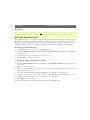
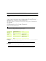
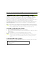
Quick Installation Procedure
Quick Installation Procedure
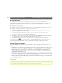
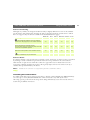
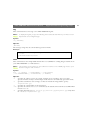
To get your AXIS 2400/2401 up and running on an Ethernet network, follow these instructions:
1. Note the serial number found on the underside label of the AXIS 2400/2401. The Ethernet
address is the same as the serial number of the unit.
2. Connect the video camera(s) to the AXIS 2400/2401.
3. Connect your AXIS 2400/2401to the network.
4. Connect the external power supply.
Note: The power supply supplied with your product is country specific. Refer to Checking the
Hardware Inventory, on page 11 and check that the type of power supply is correct.
5. Acquire a valid and unused IP address for the Video Server from your Network Administrator.
6. Assign the IP address using either the AXIS IP Installer program or ARP command, as
described below:
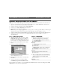
Easy - AXIS IP Installer
7a. Windows 95/98 & NT - Install the AXIS
IP Installer. You will find the installation
program on the AXIS Online CD and on
the Axis Web Site at http://www.axis.com
7b. Run the AXIS IP Installer from the Start
menu.
7c. Restart your AXIS 2400/2401.
Quick - ARP/PING
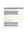
7. Windows 95/98 & NT - Start a DOS
window and type these commands:
arp -s <Server IP address> <Ethernet address>
<my PC IP address>
ping <Server IP address>
Example
arp -s 172.21.1.200 00-40-8c-10-00-86
172.21.1.193
ping 172.21.1.200
UNIX & OS/2 - Type these commands:
arp -s <IP address> <Ethernet address> temp
ping <IP address>
Example
arp -s 172.21.1.200 00:40:8c:10:00:86 temp
ping 172.21.1.200
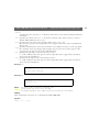
7d. Locate and select the serial number of your
AXIS 2400/2401 in the list.
7e. Enter the desired IP address, and click Set
IP address.
8. To access the Video Server Home Page,
click Home page of selected Axis-server...
8. To access the camera server Home Page,
start your Web browser and enter the IP
address in the location/address field:
http://<IP address>/
Example
http://172.21.1.200/
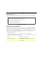
The installation is complete. Access the Web-based Administration Tools and configure the AXIS
2400/2401 to suit your user requirements.
AXIS 2400 and AXIS 2401
Video Servers
Administration Manual
AXIS 2400/2401 Administration Manual
2
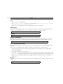
About This Document
Liability
This manual is intended for both administrators and users of the
AXIS 2400/2401 Video Server, and is applicable for software
release 1.0. It includes simple step-by-step instructions for
configuring, managing and using the AXIS 2400/2401 Video
Server within your networking environment.
It is not necessary for the reader to have any previous networking
experience to install or use this product, although some
knowledge of UNIX systems would be beneficial for developing
custom programming scripts.
Every care has been taken in the preparation of this manual; if you
detect any inaccuracies or omissions, please inform your local Axis
office which can be found on the cover of this document. Axis
Communications AB cannot be held responsible for any technical or
typographical errors and reserves the right to make changes to the
product and manuals without prior notice. Axis Communications AB
makes no warranty of any kind with regard to the material contained
within this document, including, but not limited to, the implied
warranties of merchantability and fitness for a particular purpose.
Axis Communications AB shall not be liable nor responsible for
incidental or consequential damages in connection with the
furnishing, performance or use of this material.
Readers are recommended to use this document as a supplement
to the Wizards and other on-line information available via the
Web-based interface. Superseding versions for this document
will be posted to the Axis Website, as required.
Safety Notices
Please observe all safety markings when using this product.
Caution! - Potential hazard that can damage the product.
Important! - Potential hazard that can seriously impair
operation.
Do not proceed beyond any of the above notices until you have
fully understood the implications.
Legal Considerations
Camera surveillance can be prohibited by laws that vary from
country to country. Check out the laws in your local region
before using the AXIS 2400/2401 for surveillance.
Electromagnetic Compatibility (EMC)
USA - This equipment generates, uses, and can radiate radio
frequency energy and if not installed and used in accordance
with the instruction manual, may cause interference to radio
communications. It has been tested and found to comply with
the limits for a Class A computing device pursuant to Subpart B
of Part 15 of FCC rules, which are designed to provide
reasonable protection against such interference when operated in
a commercial environment. Operation of this equipment in a
residential area is likely to cause interference in which case the
user at his/her own expense will be required to take whatever
measures may be required to correct the interference. Shielded
cables should be used with this unit to ensure compliance with
the Class A limits.
Europe
- This digital equipment fulfills the
requirements for radiated emission according to limit B of
EN55022/1994, and the requirements for immunity according
to EN50082-1/1992 residential, commercial, and light industry.
AXIS COMMUNICATIONS
<Product
Name> Quick User’s Guide
Year 2000 Compliance
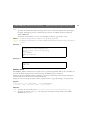
Axis Communications AB warrants that this product is Year 2000
compliant.
Trademark Acknowledgments
Acrobat, Adobe, Ethernet, IBM, Internet Explorer, LAN Manager,
Macintosh, Microsoft, Netscape Navigator, OS/2, UNIX, Windows,
WWW are registered trademarks of the respective holders. Java and
all Java-based trademarks and logos are trademarks or registered
trademarks of Sun Microsystems, Inc. in the United States and other
countries. Axis Communications AB is independent of Sun
Microsystems Inc.
Support Services
Should you require any technical assistance, please contact your local
dealer. If your questions cannot be answered immediately, your dealer
will forward your queries through the appropriate channels to ensure
you a rapid response. If you are connected to Internet, you can obtain
on-line manuals, technical support, software updates, application
software and general corporate information from any of the locations
listed below.
Axis’ CCTV Website
http://cctv.axis.com/
WWW:
http://www.axis.com
FTP:
ftp://ftp.axis.com/pub/axis
AXIS 2400/2401 Administration Manual
Revision 1.1
Part No: 16741
Dated: July 1999
Copyright © Axis Communications AB, 1996 1999
AXIS 2400/2401 Administration Manual
Table of Contents
Table of Contents
Product Overview . . . . . . . . . . . . . . . . . . . . . . . . . . . . . . . . . . . . . . . . . . . . . . . . . . . . . . . . . . 5
Features and Benefits . . . . . . . . . . . . . . . . . . . . . . . . . . . . . . . . . . . . . . . . . . . . . . . . . . . . . . . 6
Physical Description . . . . . . . . . . . . . . . . . . . . . . . . . . . . . . . . . . . . . . . . . . . . . . . . . . . . . . . . . 8
The Front Panel . . . . . . . . . . . . . . . . . . . . . . . . . . . . . . . . . . . . . . . . . . . . . . . . . . . . . . . . . . . . 8
The Rear Panel . . . . . . . . . . . . . . . . . . . . . . . . . . . . . . . . . . . . . . . . . . . . . . . . . . . . . . . . . . . 10
Installation. . . . . . . . . . . . . . . . . . . . . . . . . . . . . . . . . . . . . . . . . . . . . . . . . . . . . . . . . . . . . . . . 11
Checking the Hardware Inventory . . . . . . . . . . . . . . . . . . . . . . . . . . . . . . . . . . . . . . . . . . .
Connecting the AXIS 2400/2401 . . . . . . . . . . . . . . . . . . . . . . . . . . . . . . . . . . . . . . . . . . . .
Assigning an IP Address . . . . . . . . . . . . . . . . . . . . . . . . . . . . . . . . . . . . . . . . . . . . . . . . . . . .
Verifying the Installation . . . . . . . . . . . . . . . . . . . . . . . . . . . . . . . . . . . . . . . . . . . . . . . . . . . .
Configuring the Video Server . . . . . . . . . . . . . . . . . . . . . . . . . . . . . . . . . . . . . . . . . . . . . . . .
11
12
13
17
18
Overview of the Administration Tools . . . . . . . . . . . . . . . . . . . . . . . . . . . . . . . . . . . . . . . .
Designing your Application . . . . . . . . . . . . . . . . . . . . . . . . . . . . . . . . . . . . . . . . . . . . . . . . .
Network Settings . . . . . . . . . . . . . . . . . . . . . . . . . . . . . . . . . . . . . . . . . . . . . . . . . . . . . . . . .
Video Settings . . . . . . . . . . . . . . . . . . . . . . . . . . . . . . . . . . . . . . . . . . . . . . . . . . . . . . . . . . . .
Serial Port Settings . . . . . . . . . . . . . . . . . . . . . . . . . . . . . . . . . . . . . . . . . . . . . . . . . . . . . . . .
Pan Tilt Settings . . . . . . . . . . . . . . . . . . . . . . . . . . . . . . . . . . . . . . . . . . . . . . . . . . . . . . . . . . .
Generic Driver Settings . . . . . . . . . . . . . . . . . . . . . . . . . . . . . . . . . . . . . . . . . . . . . . . . . . . .
Configuring using FTP . . . . . . . . . . . . . . . . . . . . . . . . . . . . . . . . . . . . . . . . . . . . . . . . . . . . . .
Using the Video Server . . . . . . . . . . . . . . . . . . . . . . . . . . . . . . . . . . . . . . . . . . . . . . . . . . . . .
18
22
26
28
30
32
33
33
34
Accessing your Surveillance Images . . . . . . . . . . . . . . . . . . . . . . . . . . . . . . . . . . . . . . . . . . . 34
Positional Control of the Video Sources . . . . . . . . . . . . . . . . . . . . . . . . . . . . . . . . . . . . . . 36
Appendix A - Troubleshooting . . . . . . . . . . . . . . . . . . . . . . . . . . . . . . . . . . . . . . . . . . . . . . . 38
The Log File . . . . . . . . . . . . . . . . . . . . . . . . . . . . . . . . . . . . . . . . . . . . . . . . . . . . . . . . . . . . . .
PINGing Your IP Address . . . . . . . . . . . . . . . . . . . . . . . . . . . . . . . . . . . . . . . . . . . . . . . . . . .
Symptoms, Possible Causes and Remedial Actions . . . . . . . . . . . . . . . . . . . . . . . . . . . . .
Appendix B - Updating the Software . . . . . . . . . . . . . . . . . . . . . . . . . . . . . . . . . . . . . . . . . . .
38
39
40
42
Obtaining Updated Software . . . . . . . . . . . . . . . . . . . . . . . . . . . . . . . . . . . . . . . . . . . . . . . . 42
Upgrading the Software . . . . . . . . . . . . . . . . . . . . . . . . . . . . . . . . . . . . . . . . . . . . . . . . . . . . 42
Appendix C - Technical Specifications. . . . . . . . . . . . . . . . . . . . . . . . . . . . . . . . . . . . . . . . . . 44
Appendix D - The RS232 Interface . . . . . . . . . . . . . . . . . . . . . . . . . . . . . . . . . . . . . . . . . . . . 46
The Physical Connector . . . . . . . . . . . . . . . . . . . . . . . . . . . . . . . . . . . . . . . . . . . . . . . . . . . .
Camera Positioning . . . . . . . . . . . . . . . . . . . . . . . . . . . . . . . . . . . . . . . . . . . . . . . . . . . . . . . .
46
46
3
4
Table of Contents
AXIS 2400/2401 Administration Manual
Appendix E - CGI Parameters . . . . . . . . . . . . . . . . . . . . . . . . . . . . . . . . . . . . . . . . . . . . . . . . 51
CGI Parameters for Image Requests . . . . . . . . . . . . . . . . . . . . . . . . . . . . . . . . . . . . . . . . . .
CGI Parameters for Pan Tilt and Zoom Control . . . . . . . . . . . . . . . . . . . . . . . . . . . . . . .
CGI Parameters for Preset Positions . . . . . . . . . . . . . . . . . . . . . . . . . . . . . . . . . . . . . . . . .
CGI Parameters for Serial Port Control . . . . . . . . . . . . . . . . . . . . . . . . . . . . . . . . . . . . . . .
Appendix F - The IO Terminal Block. . . . . . . . . . . . . . . . . . . . . . . . . . . . . . . . . . . . . . . . . . .
51
53
54
54
56
Controlling and Monitoring . . . . . . . . . . . . . . . . . . . . . . . . . . . . . . . . . . . . . . . . . . . . . . . . . 58
Appendix G - Camera Applications . . . . . . . . . . . . . . . . . . . . . . . . . . . . . . . . . . . . . . . . . . . . 61
Wizard Preconfigurations . . . . . . . . . . . . . . . . . . . . . . . . . . . . . . . . . . . . . . . . . . . . . . . . . . . 61
Client Applications . . . . . . . . . . . . . . . . . . . . . . . . . . . . . . . . . . . . . . . . . . . . . . . . . . . . . . . . 62
Appendix H - The Programming Script . . . . . . . . . . . . . . . . . . . . . . . . . . . . . . . . . . . . . . . . . 63
Starting and Enabling the Editor . . . . . . . . . . . . . . . . . . . . . . . . . . . . . . . . . . . . . . . . . . . . .
Programming Script Format . . . . . . . . . . . . . . . . . . . . . . . . . . . . . . . . . . . . . . . . . . . . . . . . .
Commands . . . . . . . . . . . . . . . . . . . . . . . . . . . . . . . . . . . . . . . . . . . . . . . . . . . . . . . . . . . . . . .
Index . . . . . . . . . . . . . . . . . . . . . . . . . . . . . . . . . . . . . . . . . . . . . . . . . . . . . . . . . . . . . . . . . . . .
63
63
66
77
AXIS 2400/2401 Administration Manual
Product Overview
Product Overview
Axis’ Video Servers include a built-in Web server that enhances traditional surveillance systems and
provides added networking connectivity for distributing monitored images over a secure intranet
network, or even the Internet. Video camera management, configuration, and monitoring - all at
your fingertips through a standard Web browser; such as, Netscape Navigator or Microsoft
Internet Explorer.
The following models are currently available:
The AXIS 2400 Video Server Connecting directly to Ethernet or Fast
Ethernet networks, the AXIS 2400 Video
Server supports up to four PAL/NTSC
video cameras and is programmable for
both NTSC and PAL video systems.
The AXIS 2401 Video Server Connecting directly to Ethernet or Fast
Ethernet networks, the AXIS 2401 Video
Server provides a single video input that
accommodates any standard composite
video source and a loop-through video
output connector. The AXIS 2401 is
available for NTSC or PAL video systems.
Both product variants include a Web-based interface featuring several user-friendly Wizards that
not only simplify the installation process, but also allow for a seamless and automated integration
into your networking environment and custom applications. Furthermore, its open-network
structure minimizes the need for costly coax cabling and optimizes imaging broadcasting for a
minimal connection overhead.
The AXIS 2400/2401 is the smart and cost-effective solution for the sophisticated demands of a
modern interactive surveillance and remote monitoring system. Simple to install - and easy to use!
5
6
Product Overview
AXIS 2400/2401 Administration Manual
Features and Benefits
Ease of Use - The AXIS 2400/2401 has plug-and-picture functionality - all you need to do is
assign a valid IP address. The only software required is Microsoft Internet Explorer 4.x (used with
Axis’ ActiveX component), or Netscape 4.x or above.
Cost-effective - Increases image distribution with minimal connection overhead to provide a
reliable and low-cost resource for network imaging. Absolutely no hidden accessories; such as,
expensive software, management workstations or dedicated video cabling, is required.
Open Standards Environment - Supporting TCP/IP networking, SMTP e-mail, HTTP and
other Internet-related protocols; the AXIS 2400/2401 can be used in mixed operating system
environments; such as, Windows, UNIX, Macintosh and OS/2.
Simple Administration - Using a standard Web browser, you configure and manage the AXIS
2400/2401 directly from its own Web pages. When a new firmware release becomes available, you
can batch upgrade all of your Axis Video Servers remotely over the network using the AXIS
ThinWizard.
Standard Image Format - The AXIS 2400/2401 generates high-quality pictures in standard
JPEG format, which can be viewed using any standard Web browser.
Picture Updating - The on-board ETRAX 100 processor and revolutionary AXIS ARTPEC-1
Real Time Picture Encoder provides an amazing power-synergy to deliver up to 30 frames over
10Mbps or 100Mbps networks.
Wide Range of Applications - The AXIS 2400/2401 offers live video over the network for
enhancing and modernizing traditional CCTV systems - and much more.
The AXIS 2400/2401 allows remote CCTV and video access directly from a standard Web
browser. Users can access live images or remotely control CCTV at any time anywhere.
Accordingly, the AXIS 2400/2401 can be used for: verifying intruder alarms, traffic surveillance,
banking applications, parking lots, factory monitoring, industrial surveillance, visual security
systems, image archiving, etc. SMTP e-mail is supported which allows images to be sent as e-mail
attachments at predetermined times or events.
External Device Connection - The auxiliary inputs make it possible to trigger the AXIS
2400/2401 from external devices, e.g. IR-sensors, switches, alarm relays etc.
Pan/Tilt Device Connection - Via an RS232 or RS485 serial interface, you can combine the
AXIS 2400/2401 with a Pan/Tilt device for automatically adjusting camera orientation.
AXIS 2400/2401 Administration Manual
Product Overview
Security - The AXIS 2400/2401 includes a self-contained Web server. This means that the
camera server is secured like any other Internet host. The Network Administrator can decide
whether individuals, groups, the whole company or the whole world may access your video server.
This protection is normally implemented using the user security settings within the AXIS
2400/2401 or in combination with an organization’s Internet firewall.
Web Forum Discussions - Axis Communications have a Web forum for ideas and suggestions
for possible camera applications. Axis also maintain a collection of interesting links where you can
insert your own link to your application and keep lists of application notes, FAQs and other related
information.
Network Camera Servers Developer’s Pages - The Camera Division at Axis maintain a
specialist site for network camera developers. New exciting application ideas, tools, and
preprogramming scripts are constantly being added - this is an invaluable reference site for Axis’
development partners and OEMs. Follow the camera links and check it out at:
http://cctv.axis.com/ and http://www.axis.com/
7
Physical Description
AXIS 2400/2401 Administration Manual
Physical Description
Read the following information to familiarize yourself with the AXIS 2400/2401, making
particular note of where the connectors and indicators are located. This information provides a
useful reference during the installation of the product into your networking environment.
The Front Panel
POWER
NETWORK
AXIS 2400 Video Server
STATUS
8
VIDEO 1
VIDEO 2
VIDEO 3
VIDEO 4
1 2 3 4
75
ON
http://www.axis.com
AXIS 2400 Front Panel
AXIS 2401 Front Panel
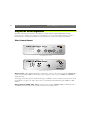
Video Inputs - The AXIS 2401 allows a single video source to be connected via the VIDEO IN
connector; the AXIS 2400 accommodates up to 4 separate video sources (VIDEO 1- VIDEO 4)
simultaneously.
Each supported video input is terminated using a coax/BNC connector. Physical connections made
using RG59, 75 ohm coax video cable; have a recommended maximum length of 800 feet (250
meters).
Video Output (AXIS 2401 only) - A single video output (VIDEO OUT) terminated with a
coax/BNC connector allows direct connection of an external monitor.
AXIS 2400/2401 Administration Manual
Physical Description
DIP Switches - DIP switches provide the line termination for each supported video input. All
units are shipped with the line termination enabled for each supported video input; that is, with the
DIP switches set in the down-position.
If the AXIS 2400/2401 is to be connected in parallel with other equipment, disable the input
termination by turning the corresponding DIP switch to the up-position (OFF). Failure to do this
can cause the picture quality to be impaired.
Status Indicator - The multi-colored status indicator defines the operational status of the server,
as described below:
• green - the indicator flashes briefly and momentarily displays orange during the start-up and
self-test routines; the indicator then displays green to indicate a healthy unit status.
• red - the indicator will display red only if a problem with the AXIS 2400/2401 has occurred.
Refer to Appendix A - Troubleshooting.
Note: The Status indicator also displays orange when setting the factory default settings, as described in
Reinstating the Factory Default Settings, on page 25.
Network Indicator - After completion of the startup and self test routines, the multi-colored
Network Indicator flashes independently, as follows:
• yellow - indicating network activity on a 10Mbps Ethernet network
• green - indicating network activity on a 100Mbps Fast Ethernet network
• red - indicating no physical connection to the network.
Power Indicator - The Power indicator is normally lit while power is applied. If it is not lit, or it
flashes, there is problem with the AXIS 2400/2401 external power source.
Control Button - Located centrally between the supported video input connectors on the AXIS
2400, and to the left of the loop-through video output on the AXIS 2401; this button is recessed
within the product casing. Using a suitably pointed object, you press this button to restore the
factory default settings, as described in Reinstating the Factory Default Settings, on page 25.
Serial Number - Located on the underside label of the AXIS 2400/2401, the serial number is
identical to the Ethernet address of the unit.
9
10
Physical Description
AXIS 2400/2401 Administration Manual
The Rear Panel
1 2 3 4 5 6 7 8
POWER
PS-D
COM 2
COM 1
ETHERNET
10/100
9 10 11 12 13 14 15 16
AXIS 2400/2401 Rear Panel
I/O Terminal Block - The I/O Terminal Block connector is located between the two serial
ports on the rear panel and provides the physical interface to one relay switch output, four digital
photo-coupled inputs, and an RS-485 interface. For details, refer to Appendix F - The IO Terminal
Block.
Use this connector for transmitting data over a multi-drop communication lines, RS485 Pan Tilt
devices, and external triggering - typically associated with CCTV equipment. The connector can be
utilized as an alternative connection point for DC supply to the unit.
RS-232 Serial Connectors - Two 9-pin D-sub connectors providing RS-232 serial
connection, one of which is multiplexed with the RS-485 port via the Terminal Block Connector.
Typically used for Pan/Tilt device interface.
Network Connector - The AXIS 2400/2401 is designed for 10 Mbps Ethernet and 100 Mbps
Fast Ethernet networks and connects to the network via a twisted pair category 5 cable (10baseT
and 100baseTX) terminated using a standard RG-45 connector. Supporting NWAY, the AXIS
2400/2401 detects the speed of the local network segment and varies the speed of data
communication accordingly, between 10 Mbps and 100 Mbps.
Power Supply Connector - A single Jack socket (PS-D) for connection of AXIS 2400/2401
power supply. The terminal block connector provides an auxiliary connection point for AC or DC
power to the unit.
Note: The power supply supplied with your AXIS 2400/2401 is country specific. Please check that the
type of power supply you are using is correct. See page 11.
AXIS 2400/2401 Administration Manual
Installation
Installation
Follow the instructions included in this section to install the AXIS 2400/2401 into your
networking environment. Each phase of the documented installation procedure is summarized
below:
•
•
•
•
Checking the Hardware Inventory
Connecting the AXIS 2400/2401
Assigning an IP Address
Verifying the Installation
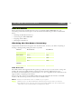
Checking the Hardware Inventory
Unpack and check all the items against the check list below. Contact your dealer if anything is
missing or damaged. All packing material is recyclable.
Hardware
Model Variants
Part Numbers
Video Server
AXIS 2400
0092- 001- 01
AXIS 2401 (NTSC)
0092- 007- 01
AXIS 2401 (PAL)
0092- 008- 01
Europe
14233
UK
14234
Australia
14255
USA
14253
Japan
14254
Media
Title
Part Numbers
CD-ROM
AXIS Online CD
-
Printed Materials
AXIS 2400/2401 Administration Manual
16741
Power Supply
(PS-D)
AXIS Online CD
The AXIS Online CD supplied with this product provides an easy-to-use electronic catalog that
includes all of the latest AXIS Utilities Software, Product Software, White Papers, User
Documents, Technical References, Technical Notes, etc. It is compatible for use within all of the
supported Axis computing environments.
You can view the contents of the AXIS Online CD via the Adobe Reader interface or HTML
interface. All documents presented on the CD are in PDF format.
Notes: If Adobe Acrobat Reader 3.0 is not installed on your system:
•Windows users can click the Get Adobe Reader button from the main user interface.
•Non-Windows users can locate and run the appropriate installer from the tools/Acrobat/
folder. Refer to the readme.txt file for full path name details.
11
12
Installation
AXIS 2400/2401 Administration Manual
Connecting the AXIS 2400/2401
The AXIS 2400 accommodates up to four coax/BNC connected video sources; whereas, the AXIS
2401 allows single video connection with a loop-through video output for connection to an
external monitor. The AXIS 2401 Web applications also support integrated image feed from other
Axis camera and video servers on the network within a single-presentation interface.
Both models display video images in single, or traditional quad picture format, delivering up to 25
PAL and 30 NTSC frames/second over 10/100Mbs networks.
Notes: •NTSC delivering 525 lines of resolution at 60 half-frames per second is the common standard in
the United States; whereas, PAL delivers 625 lines at 50 half-frames per second and is the dominant television standard in Europe.
•The AXIS 2401 is supplied as either an NTSC or PAL-specific unit. The AXIS 2400 is programmable for both PAL and NTSC operation.
Connecting your Camera(s)
Connect the video output of your camera(s) to the AXIS 2400/2401 video port(s) using standard
75 ohm coaxial video cable, terminated with a BNC-connector.
Notes: •The AXIS 2400/2401will experience lower image framerate when simultaneously accessed by
multiple clients. In particular, you will notice this on the AXIS 2400 when two or more different
video sources are accessed simultaneously.
•Use a BNC-to-RCA conver ter if your camera is supplied with a standard phono-type (RCA)
connector.
Connecting your Server to the Network
Follow the instructions below to connect the AXIS 2400/2401to your network:
1. Note the serial number of your AXIS 2400/2401 for future reference during the installation
procedure. This is located on the underside label of the unit.
2. Connect your video server to the network with twisted pair category 5 cable (10baseT or
100baseTX) terminated using a standard RG-45 connector.
3. Connect the power supply to the video server.
4. Check that the Power Indicator is constantly lit.
AXIS 2400/2401 Administration Manual
Installation
Assigning an IP Address
To enable access to your video server you must first assign it an appropriate IP Address.
Before you begin:
•
•
•
•
Make sure the AXIS 2400/2401 is powered up and attached to the network.
IP Address: Acquire an unused IP address from your Network Administrator.
Ser ver Privileges: You need root privileges for UNIX; administrator privileges for Windows NT.
Ethernet Address: Each AXIS 2400/2401 is pre-configured with a unique Ethernet Address that is
based upon the unit serial number, which you can find printed on the underside label of the unit. You
will need to know the Ethernet address of your AXIS 2400/2401 to install the unit.
Mapping a Host Name to the IP Address
If you are using host names, you can map a unique host name to the acquired IP address. Refer to
your system manuals or Network Administrator for instructions on how to perform the name
mapping on your particular system.
Note: If the host name has not been included in the system host table, you can still perform the following instructions on how to download the IP address. In this case, simply replace the host name
entry with the IP address wherever required.
Choosing an Appropriate Method
Set the IP address using an appropriate method for your operating system from the table below:
Method
Operating Systems
Refer to...
AXIS IP Installer
Windows 95/98 and NT
“Using the AXIS IP Installer” on page
14
ARP
Requires the IP address for each new device to
be downloaded individually and is not appropriate for use over routers.
Windows 95/98 and NT
“Using ARP in Windows 95/98 and
Windows NT” on page 15
UNIX, OS/2
“Using ARP in UNIX and OS/2” on
page 15
RARP
UNIX
Refer to Using RARP in UNIX, on
page 16.
UNIX
Refer to Using BOOTP in UNIX, on
page 16
Requiring a RARP daemon on your system, this
method downloads the IP address to each
device automatically and operates within a single network segment only.
BOOTP
Requiring a BOOTP daemon on your system,
this method operates over the entire network.
A request to an active daemon initiates a search
of the boot table to find an entry matching the
unit’s Ethernet address. The daemon downloads the IP address to the device if a match is
found.
13
14
Installation
AXIS 2400/2401 Administration Manual
Important!
When installing your AXIS 2400/2401, do not use the default or the IP address featured as examples
within this document. Always consult your Network Administrator before assigning an IP address.
Using the AXIS IP Installer
The AXIS IP Installer is a Windows 95/98 & NT program that simplifies the procedure for setting
IP addresses within Axis’ networking products; it also allows you to conveniently access the home
Web page of any Axis ThinServer connected to your network. The program is available on the
AXIS Online CD and from Axis’ Websites at http://cctv.axis.com/ and http://www.axis.com/
Installing the AXIS IP Installer:
1. On the AXIS Online CD, click on the Software button.
2. Select the AXIS IP Installer and click Install. The AXIS IP Installer - Setup dialog is displayed
on the screen.
3. Follow the instructions as they appear on the screen.
4. Click Finish to complete the setup.
Setting the IP Address with AXIS IP Installer:
1. Run the AXIS IP Installer from the Start menu. The AXIS IP Installer dialog is displayed on
the screen.
2. Restart your camera server.
3. Select the serial number of your camera server in the list. The serial number is identical to the
Ethernet address of the unit.
4. Enter the desired IP address. Click Set IP address. The IP address will now be set.
5. To access the home page of the camera server, click Home page of selected Axis-server... You
can now configure the video server according to your requirements.
6. Click OK to exit the program.
For more help during the installation of the IP address, click Help or F1.
AXIS 2400/2401 Administration Manual
Installation
Using ARP in Windows 95/98 and Windows NT
To download the IP address and verify the communication, start a DOS window and type the
following commands:
arp -s <server IP address> <Ethernet address>
ping <server IP address>
Example:
arp -s 172.21.1.200 00-40-8c-10-00-86
ping 172.21.1.200
The host will return ‘Reply from 172.21.1.200 ...’ or some similar message. This means that
the address has been set and the communication is established.
Important!
Windows 95 only: When using the Windows 95 implementation of ARP, change the first line to:
arp -s <server IP address> <Ethernet address> <w95host IP address>, where <w95host IP address> is the IP
address of your Windows 95 host.
Example:
arp -s 172.21.1.200 00-40-8c-10-00-86 172.21.1.193
ping 172.21.1.200
Note: When you execute the PING command for the first time, you will experience a significantly
longer response time than usual.
Using ARP in UNIX and OS/2
To download the IP address and verify the communication, type the following commands:
arp -s <server IP address> <Ethernet address> temp
ping <server IP address>
Example:
arp -s 172.21.1.200 00:40:8c:10:00:86 temp
ping 172.21.1.200
The host will return ‘172.21.1.200 is alive ’, or some similar message to indicate that the
address has been set and the communication is established.
Note: When you execute the PING command for the first time, you may experience a significantly
longer response time than usual.
15
16
Installation
AXIS 2400/2401 Administration Manual
Using RARP in UNIX
Follow these steps to use the RARP method in UNIX:
1. Append the following line to your Ethernet Address table. This is typically performed using
the command /etc/ethers:
<Ethernet address> <host name>
Example:
00:40:8c:10:00:86 videoserv
2. If necessary, update your host table and alias name databases as described required by your system.
3. If it is not already running, start the RARP daemon, typically done using the command rarpd -a.
4. Restart the AXIS 2400/2401 to download the IP address.
Using BOOTP in UNIX
Follow these steps to use the BOOTP method:
1. Append the following entry to your boot table. This is typically done using the command
/etc/bootptab:
<host name>:ht=<hardware type>:vm=<vendor magic>:\
:ha=<hardware address>:ip=<IP address>:\
:sm=<subnet mask>:gw=<gateway field>
where:
ht
= ether
vm
= rfc1048
ha
= The Ethernet address of the AXIS 2400/2401
ip
= The IP address of the AXIS 2400/2401
sm
= The subnet mask
gw
= The default router address
Example:
videoserv:ht=ether:vm=rfc1048:\
:ha=00408c100086:ip=172.21.1.200:\
:sm=255.255.255.0:gw=172.21.1.1
2. If necessary, update your host table and alias name databases as described required by your system.
3. If it is not already running, start the BOOTP daemon. This is typically done using the command
bootpd.
4. Restart the AXIS 2400/2401 to download the IP address, default router address, and subnet mask.
AXIS 2400/2401 Administration Manual
Installation
Verifying the Installation
After assigning an IP address, verify the connection between the AXIS 2400/2401 and the network:
1. Start your Web browser (see note below) and enter the name or IP address in the
Location/Address field:
Example
http://172.21.1.200/
Important!
When using Microsoft Internet Explorer for the first time, you must then temporarily lower your security settings to
perform a one-time-only installation of Axis' ActiveX component onto your workstation, as described below:
• From the View menu, select Internet Options
• Click the Security tab and make note of your current security settings
• Set the security level to Low and click OK
• Type the Internet Address or Host Name of your AXIS 2400/2401 into the Location field
• A dialog asking if you want to install ATLCamImage.ocx will appear. Click yes to start the installation
• Once the AxtiveX installation is complete, return the security settings to their original value, as noted above
Note: This functionality is currently under review in order to increase ease-of-use; new instructions relating to this
will shortly will be available from our Website http
ttp://cctv.axis.com/
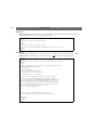
2. The Welcome Page of your AXIS 2400/2401 is now displayed:
3. To continue the setup process and configure your own application, click the Admin button in
the top left corner of this window and proceed to Configuring the Video Server, on page 18.
Log on as user root with the default password pass.
Note: Web pages are kept locally for fast browsing, and your browser may occasionally display a cached
image as opposed to a newly taken snapshot. When this happens, simply click Reload/Refresh in
your Web browser. Some browsers may even force you to clear the cache, or use forced reload,
e.g. Shift+Reload in Netscape.
17
18
Configuring the Video Server
AXIS 2400/2401 Administration Manual
Configuring the Video Server
This section is targeted specifically to personnel responsible for the administration of the AXIS
2400/2401. The Administrator(s) is granted with high-level privileges denied to the ordinary
user(s).
Before you begin:
To access the AXIS 2400/2401configuration pages, you must first set the Internet address as described in Assigning
an IP Address, on page 13 .
You configure the AXIS 2400/2401 from a standard Web browser such as Netscape Navigator or
Microsoft Internet Explorer.
As a viable alternative to managing and configuring the AXIS 2400/2401using a Web browser, you
can alternatively edit the system configuration file using a text editor and upload the file to the
AXIS 2400/2401using FTP. For further information please refer to Configuring using FTP, on page
33.
Overview of the Administration Tools
The Web-based Administration tools are displayed in a graphical user interface that allows simple
point-and-click display of the system tools. Several user-friendly Wizards are provided to guide you
through every aspect of the installation; from designing the user interface and configuring the
supported networking protocols, right down to integrating the unit into your specific application
environment - it is incredibly easy!
Important!
On-line help
is available on every page within the AXIS 2400/2401 Web interface. This information is of
particular relevance when configuring the unit and should be used as a first point of reference for resolving any
administration queries. The help system is stored internally in the AXIS 2400/2401.
Following the instructions provided within this section, use the Web-based Administration tools
for configuring and managing your AXIS 2400/2401.
AXIS 2400/2401 Administration Manual
Configuring the Video Server
Accessing the Tools
Follow the instructions below to access the Administration tools using a standard Web browser:
1. Start the Web browser and enter the name or Internet address of the AXIS 2400/2401on the
location/address field.
Example
http://172.21.1.200/
Important!
If this is the first time you have accessed the AXIS 2400/2401, the Welcome page will be now be displayed. In this case, click the Administration button and proceed to configure your application using the
Installation Wizard prior to proceeding with the next step.
Note: When accessing the AXIS 2400/2401 for the first time using Microsoft Internet Explorer, you
must temporarily lower your security settings to perform a one-time-only installation of Axis' ActiveX
component onto your workstation, as described on page 17.
The Administrator(s) can choose not to display the Administration and other navigational buttons from
the user interface. Selecting this feature within in a Wizard ultimately means that the Administration
tools can then only be accessed by entering the full Admin address into the URL of the Web browser ;
for example: http://172.21.1.200/admin.html
2. Your defined Application page is now displayed. Click the Admin button to display the
Administration Overview page and access the system Administration tools.
Note: A prompt for a username and password is displayed when entering these pages for the first time
in a Web browser session. At the prompt, log on as root and use the default password pass. It is
recommended that you change the password of your AXIS 2400/2401 as soon as possible.
3. The various components of your video system are represented as icons within the displayed
graphic. Simply click the component part you want to configure. As an Administrator, you
configure and modify the system directly from this page.
19
20
Configuring the Video Server
AXIS 2400/2401 Administration Manual
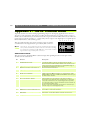
Tools Overview
The following table provides a one-stop overview of the information and services available from the
Administration pages:
Service
Administration Overview
Description
• The First-time Installation Wizard allows novice administrators to automatically set
the most important system parameters and quickly establish an appropriate application for the system users.
View Application
•
Displays the page and picture format that is presented to your users. Use this page
as a a reference after making any changes to your application design.
Help Contents
•
Displays the table of contents for the On-line Help
Support
•
Displays support and trouble-shooting information.
Design Application Settings •
Layout and Programming Wizard: design the look-and-feel of the user interface with
an easy-to-use Wizard. Choose Surveillance System or Web Attraction preconfigurations and refine the application specifically for your user needs.
•
Programming Script Editor: create programming scripts yourself using the embedded text editor - recommended for advanced users only.
Network Settings
•
Specify the system settings for each of the supported networking protocols, using a
Wizard or manually via the Detailed View; including:
- TCP/IP (Network settings)
- DNS (Domain Name System)
- SMTP (E-Mail)
Video Server Settings
•
Set the system date & time, manually or automatically
•
Define the username and password for administratror(s) and user(s)
•
View parameter list and log file
•
Emergency Settings: Restart the unit or set server parameters to factory default.
AXIS 2400/2401 Administration Manual
Configuring the Video Server
Specific Settings
Description
Video Settings
Enable/Disable video sources and specify which Pan Tilt driver (serial port) the attached
video camera is connected to - if any. Note: Two different icons are displayed to
differentiate video sources not connected to Pan Tilt devices (icon-left) from those that are
(icon-right). For each source specify:
Configure Serial Port
Pan Tilt Settings
•
Image settings: set the image features; such as: displaying text, clock, color or Black &
White etc
•
Video Input/Modulation: to define the video transmission standard automatically or
manually.
•
Preset Positions: used for creating Pan Tilt and Zoom preset conditions and only visible
if the selected video source is connected to a pan tilt device.
For each of the two supported serial ports specify:
•
Purpose: Pan Tilt, Generic or None
•
Interface Mode/Serial mode: RS485 or RS232 (Port 1 only)
•
Communication settings: Baud Rate (bps), Data Bits (length), Stop and Parity Bits
A Pan Tilt icon is displayed underneath a Serial Port icon only if the purpose of the
respective serial port is defined as Pan Tilt.
Select the Pan Tilt driver and define the driver specific settings: Canon VC-C3, Sony
EVI-D30, Sony EVI-D31, Sony EVI-G20, Sony EVI-G21, VideMech, Ernitec, ICU and
Diamond Smartscan are all supported.
Generic Settings
A Generic icon is displayed underneath a Serial Port icon only if the purpose of the
respective serial port is defined as Generic. The Generic driver is often referred to as
terminal server or serial server and enables complete control of the Axis server serial ports
from third-party client applications.
Configure the port as an HTTP input/output or TCP input/output and save the changes.
21
22
Configuring the Video Server
AXIS 2400/2401 Administration Manual
Designing your Application
As an Administrator, you decide the general look and feel of the user interface and determine:
• the appearance of the user interface
• how video images are to be displayed to user
• the services and functions available to user
Click the Application Design icon within the graphic user interface to display the settings for your
application.
Application - Layout
Design the layout of the application specifically to your users needs, using either the Wizard or
Programming Text Editor.
Important!
The Administrator can choose not to display the Administration and other navigational buttons from the
user interface. Selecting this feature within in the Wizard ultimately means that the Administration tools
can then only be accessed by entering the full Admin address into the URL of the Web browser, as
defined below:
http://172.21.1.200/html/admin.html
Using the Layout and Programming Wizard
From the Application Design page, click the Layout and Programming Wizard button
and
follow the on-line instructions to automatically configure the look-and-feel of the user interface.
You can choose Surveillance System or Web Attraction preconfigurations and refine the
application specifically to your needs by selecting from several of the available features, including:
alarm triggering, picture storage using FTP, image distribution via e-mail, etc.
You will find that the Wizard helps you not only to define the functionality of your system; such
as: Quad system with or without pre/post alarm storage, picture size and magnification parameters,
but also allows you to decide some of the more cosmetic aspects of system presentation; including:
background, logo, user button and product title presentation.
Click the Finish button to save the defined configuration to the Video Server.
Tip!
Spend some time to go through the different Application Wizards and try various settings. Click the
View Application button to view the results.
AXIS 2400/2401 Administration Manual
Configuring the Video Server
Wizard Overview
As a supplement to the information provided by the available Help, the table below provides a
one-stop-reference for the parameters established by the Application Wizard:
Parameter
Image size
Image Scale
Options
• Huge size
(interlaced image,
NTSC=704 x 480,
PAL=704 x 576)
•
Full size
(NTSC=352 x 240,
PAL=352 x 288)
•
Half size
(NTSC=176 x 112,
PAL=176 x 144)
x2 or x4
Description
You can adjust the size and appearance of the displayed
images: ranging from small, highly compressed pictures;
to large, high-quality JPEG images.
Typical file sizes for each of the available image sizes are
dependent upon a number of different factors. Generally,
low compression and large images sizes produce large
filesizes; although higher quality images that include a lot
of detail, will also increase resultant file size.
Note: NTSC (60Hz) is the common standard in the USA,
whereas PAL (50Hz) dominates in Europe.
To allow an increase in the image display size without
impacting network bandwidth, you can choose to scale
your images by a multiple factors of two (x2) or four (x4).
Increasing a halfsize image by x2 enlarges the picture
area to that of a fullsize image - delivering a lower picture
resolution, but using approximately one quarter of the
network bandwidth demanded to display a fullsize image.
Page style
•
•
•
Show gray background picture The Administrator can choose not to display the
Show title, line and Axis logo Administration and other navigational buttons from the
user interface. Selecting this feature within in the Wizard
Show buttons (e.g. Help,
ultimately means that the Administration tools can then
Admin)
only be accessed by entering the full Admin address into
the URL of the Web browser, as defined below:
http://172.21.1.200/admin.html
Programming Script Editor
The Programming Script Editor editor offers advanced administrators and developers with an even
greater level of flexibility for customizing the application specifically to meet their user needs. Using
the on-line help as a reference, advanced users follow the instructions below to quickly develop
programming scripts for time and/or alarm-triggered events:
Tip!
As a supplement to the information provided in the on-line help, the scripting language and syntax is also
fully explained in Appendix H- The Programming Script. Several tips and examples are also provided.
1. Click the Programming Script Editor button to start the editor.
2. Enter a valid script in the main window and then click the Save button to deposit the script in
product memory.
3. Check the Enable box to activate the programming scripts in your system.
23
24
Configuring the Video Server
AXIS 2400/2401 Administration Manual
Notes: •Scripts are not activated until the Enabled button is checked and the script is re-saved.
•Saving new scripts automatically removes any existing script(s) previously saved with the Editor.
•Previously saved scripts are automatically displayed when the Programming Script Editor is
opened.
Server Settings
Click the Video Server icon within the graphic user interface to display and/or edit the following
settings:
Date and Time
You click the Date and Time icon and set the current date and time either Automatically, or
Manually. Setting the date and time Automatically requires you to provide the Internet Address of a
local NTP server and select your local time zone from the available drop-down dialog.
Click Save to register the settings with the Video Server.
Security
To prevent any unauthorized use of the Video Server, access is strictly password protected and
restricted to defined Users and the Administrator(s) only. Administrator(s) have exclusive access to
the product Administration Tools and determine the registration of all ordinary users.
Notes: Although, the Administrator’s default username and password (set to root and pass respectively)
can be used for logging in to the unit for the first time, it is strongly recommended that you
change the Administrator (root) password of your AXIS 2400/2401 as soon as possible - since all
Axis products are shipped with the same password as default.
As an Administrator, you click the Security button to either:
• define or edit the Administrator password (the Administrator username is permanently set to
root, with password default to pass), or
• define, add and delete user names and passwords
Important!
By default, the AXIS 2400/2401 supports anonymous user access, which means that anybody on the
Internet/intranet has access to the video images from a Web browser.
Should you wish to restrict access, simply enter the usernames and passwords of authorized users in the
General Settings - Security page. If the anonymous user service is satisfactory for your application, simply
do not add any users.
Note: Only characters a - z, A - Z and 0 - 9 are valid when entering usernames and passwords.
AXIS 2400/2401 Administration Manual
Configuring the Video Server
The Log File
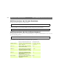
All system messages are recorded in a single log file and stored in product memory. Consequently,
the file can be used as reference for examining system events. It can also serve as a useful diagnostic
tool when attempting to resolve any problem that might occur. See also Appendix A Troubleshooting.
Follow the instructions below to display all Video Server messages since the last Restart of the
system:
1. Click the Video Server icon in the graphic interface.
2. Click the View Log File button. All recent commands are displayed in a separate window.
Viewing the Parameter List
The Parameter List provides a comprehensive list of all of the system parameters and their current
settings. Follow the instructions below to display the list:
1. Click the Video Sever icon in the graphic interface.
2. Click View Parameter List to display the list.
3. Click Print to print a hard copy of the displayed list to your default printer.
Emergency Actions
In certain circumstances it may become necessary to restart or return the Video Server to its
Factory Default settings, or initiate a hardware Restart of the unit. Both emergency actions can be
initiated by clicking the appropriate button on this page.
Note: Clicking Factor y Default deletes any previously defined layout and preprogramming configurations.
Reinstating the Factory Default Settings
Follow the instructions below to reinstate the factory default settings in AXIS 2400/2401:
1. Switch off the AXIS 2400/2401by disconnecting the power cord.
2. Using a suitably pointed object, press and continue to hold the Control button depressed.
Note: The Control Button is recessed within the product casing and located between the VIDEO 3 and
VIDEO 4 input connectors on the AXIS 2400, and to the left of the VIDEO OUT connector on
the AXIS 2401.
3. While continuing to hold the Control Button depressed, reconnect the power supply cable to
the video server.
4. When the Status LED starts flashing yellow, release the Control Button for at least 2 seconds.
5. Press and continue to hold the Control Button until the Status indicator permanently displays
yellow.
25
26
Configuring the Video Server
AXIS 2400/2401 Administration Manual
The AXIS 2400/2401is now reset to factory default settings. Restart the AXIS 2400/2401by
disconnecting and then reconnecting the power cable.
Note: The Ethernet address remains unchanged, but all other parameters including the IP address are
reset. Refer to Assigning an IP Address, on page 13 for details on how to set the IP number.
Network Settings
The AXIS 2400/2401 supports the following networking protocols that are configured directly via
Network Settings:
• Transmission Control Protocol/Internet Protocol (TCP/IP) - used by the Video Server for
transmitting data over the network.
• Domain Name System (DNS) - the Internet service used by the product for translating domain
names into Internet Addresses.
• Simple Mail Transfer Protocol (SMTP) - this is the protocol for sending e-mail messages
between e-mail servers on the network. The AXIS 2400/2401 can be pre-programmed to send
images as e-mail attachments to pre-defined addresses.
Note: •DNS ser vers are only necessary if scripts with DNS names are used. If you do not use scripts or
only use IP addresses in scripts, you need not enter a DNS server reference.
Click the Network icon within the graphic user interface, or click the Network Settings button to
configure the above protocols, using the Wizard, or by clicking Detailed View.
Using the Wizard
The Wizard guides you through the setup procedures for each of the above protocols - one at a
time. After completing one protocol, you optionally proceed to configure another protocol.
Clicking the Finish button on the last page of the Wizard saves the new settings to the Video
Server.
AXIS 2400/2401 Administration Manual
Configuring the Video Server
27
Using the Detailed View
Clicking the Detailed View displays the Network Settings dialog which is navigated by clicking
any visible tag. From this dialog you can display, edit and refine the settings for any supported
network protocol.
Note: Any changes that you make are only implemented when you click the OK button; consequently,
all of the protocols can be safely browsed and edited before deciding to save the settings.
With reference to the on-line help information and the table below, use the Detailed View
manually configure the Network Settings:
to
TCP/IP Parameters Description
BOOTP
Enable the BOOTP protocol for downloading the Internet address automatically. For further
information on using BOOTP see also Using BOOTP in UNIX, on page 16. If you intend to use
the AXIS IP Installer BOOTP must be enabled.
RARP
IP Address
Enable the RARP protocol for downloading the Internet address automatically to the unit. For
further information on using RARP, see also Using BOOTP in UNIX, on page 16.
Specifies the unique 32-bit IP address of your unit.
Default Router
Defines the default router for the AXIS 2400/2401 which by default, is set to automatic router
search. If script applications the default router must be defined.
Subnet Mask
Defines the subnet mask for the AXIS 2400/2401. Used for determining when the traffic
should be sent via a router. The default 0.0.0.0 indicates automatic router sensing. If script
applications the subnet mask must be defined.
Bandwidth
Default to unlimited, this parameter defines the network bandwidth restriction for the video
server; particularly useful for connection to busy and/or heavily loaded networks.
DNS Parameters
Primary DNS
Description
Defines the IP address of the primary DNS server. Used for identifying computers with names
instead of IP addresses.
Secondary DNS
The IP address of the secondary DNS server. The secondary DNS server will be used in case
the primary DNS server is unavailable or disconnected.
SMTP Parameters
SMTP Mail Server
SMTP Return
Address
Description
Defines the server that is to provide your e-mail facilities.
The reply address for e-mails sent by the AXIS 2400/2401; that is, the name address that is to
appear in the ‘sent by’ field of the dispatched e-mail.
Configuring the Video Server
28
AXIS 2400/2401 Administration Manual
Video Settings
Each Video icon within the graphic display represents a supported video input to the AXIS
2400/2401. An icon that is dull or opaque in color indicates the relative video source is not
enabled; whereas, a cross x visible to the left of the icon suggests that the associated video signal is
not present at the input.
Click the appropriate button to configure your video source, including:
•
•
•
•
•
Video enabling and disabling
Specifying the Pan Tilt Serial Port for the connected video camera
Setting the image features as displaying text, clock, color or B&W etc
Detecting the video modulation standard
Editing PTZ (pan, tilt, zoom) preset positions
Image Settings
You click the Image Settings button to set the image features for the supported video source(s).
As the AXIS 2400 supports up to four video inputs, you can optionally choose to implement your
preferred settings generically - that is, valid for all connected video sources, or specifically - limiting
your settings to the video source previously selected in the graphic only.
From the Apply settings to drop-down dialog, you select whether your settings are to be applied
generically or specifically; that is, Video 1’s or All Videos.
With reference to the table below, configure the image settings to match your application
demands:
General Parameter
Display date & time on Image
Description
Check to enable time display within the selected video source(s).
Display text on image
Enable or disable the display of a defined text string within the selected video
image. Type the text string that you want to display within the Text field.
Miscellaneous Settings
Color
Compression
Choose to display Color or Black and White video images.
Determines the compression factor for the selected video source: min, low,
medium, high or very high. Minimum (min) compression optimizes picture quality,
but generates larger image file sizes that demand greater network bandwidth.
Notes: •Image control can also be achieved directly using CGI parameters in the image URL.
•Using CGI parameters embedded in a URL request temporarily overrides any parameters
defined within the Image Settings dialog.
•For fur ther information on using CGI Parameters, see also Appendix E - CGI Parameters.
AXIS 2400/2401 Administration Manual
Configuring the Video Server
Input Modulation
Important!
The AXIS 2400/2401suppor ts today’s two most popular video standards - NTSC and PAL:
NTSC delivers 525 lines of resolution at 60 half-frames per second is the common standard in the
United States; whereas, PAL delivers 625 lines at 50 half-frames per second and is the dominant video
standard in Europe.
The AXIS 2400 suppor ts NTSC, PAL and their derived standards; whereas the AXIS 2401 is supplied as
either an NTSC or PAL-specific unit.
Automatic Detect-and-Store for the AXIS 2401
The AXIS 2401is supplied as either a NTSC or PAL-specific unit; simply click the Video Input
Modulation button from the Video Settings page to automatically detect and store an appropriate
derivative-standard for your video input.
Automatic or Manual Selection for the AXIS 2400
The AXIS 2400 is fully compatible between both NTSC or PAL transmission protocols and
supports several derivative modulation standards that are chosen either Manually or Automatically.
From the Video Settings page, you click the Video Input/Modulation button and select whether
the settings are to be applied generically or specifically; that is, Video 1’s or All Videos. Using either
method described below, you then define the transmission standard for the unit:
Automatically - Simply click the Start button to initiate a search of the selected video source(s).
An appropriate modulation type is then automatically assigned to the selected source(s).
Manually - Select a specific modulation type from the drop-down dialog box, as detailed below:
• PAL BGH/NTSC M:
• NTC 4.43, 50Hz / PAL 4.43, 60Hz
• PAL N/NTSC 4.43, 60Hz
• NTSC N/PAL M
• SECAM / PAL 4.43, 60Hz
Clicking Save registers your the settings with the Video Server.
29
30
Configuring the Video Server
AXIS 2400/2401 Administration Manual
Preset Positions
To enable quick and accurate camera PTZ positioning to known camera hotspots, the
Administrator can control and record any camera orientation as a named entity - creating up to
twenty Preset Positions that can be used at any time by the Administrator(s), or Users.
Defining Preset Positions
The camera orientation for the selected video source is controlled by Pan Tilt and Zoom control
bars. Follow the instructions below to define a preset position:
1. Click the Preset Position button. An image taken from the selected source - at its current
position - is displayed in a new window.
2. Using the Pan Tilt and Zoom control bars, move the camera to the desired position.
3. Enter a descriptive name in the Current Position field.
4. Click Save to register the new preset position with the AXIS 2400/2401 and then check that
the entered name is included in the Preset Positions drop-down list.
5. Click Remove only if you want to remove this or any other preset position in the list.
Established preset positions are reinstated from the Preset Positions drop-down dialog in the
application viewing environment, or by the user(s) when viewing a specific video source.
Serial Port Settings
The AXIS 2400/2401is supplied with two internal serial ports managed directly from the user
interface:
• Serial Port 1- typically used for controlling CCTV devices; such as, PTZ devices. This port can
be logically connected to the RS232 COM 1 port or the RS485/422 port on the Terminal
Block Connector; consequently, it is configurable as either an RS232 or RS485/422 port.
Click the Port1 within the graphic interface to determine the Purpose, Interface Mode and
Communication Settings for port.
• Serial Port 2 - logically connected to the COM2; this port is also used for connecting Pan/tilt
devices, but additionally provides a high-speed RS232 interface for connecting accessory equipment; such as, VCRs and badge readers to the AXIS 2400/2401.
Click the Port 2 icon within the graphic interface to determine the Purpose and Communication Settings for the port.
Important!
Some pan tilt units are external devices; that are, standalone devices that connect to a fixed video camera without inherent pan-tilt-zoom support. Unless stated to the contrary, Pan Tilt devices are assumed
to be in-built mechanisms within the video camera throughout this document.
AXIS 2400/2401 Administration Manual
Configuring the Video Server
Purpose
Both serial ports - Port 1 and Port 2 - can be designated as either of the following:
• Generic - the AXIS 2400/2401, through the Generic driver, has terminal server capabilities;
consequently, third party applications can have complete control of the serial ports using TCP
or HTTP. For more information see Appendix D - The RS232 Interface and Appendix E - CGI
Parameters.
• Pan Tilt - from the drop down dialog choose from several Pan Tilt drivers supported as standard
by the AXIS 2400/2401. A list of currently supported drivers is provided in Supported Pan Tilt
Drivers, on page 48.
• None - if you are not connecting a Pan Tilt or Generic driver to the port.
Interface Mode
From the drop-down dialog you can configure COM1 as either an RS232 or RS485 port. Selecting
the former logically connects Serial Port 1 to the COM 1 connector; whereas the latter connects
the port to the Terminal Block Connector.
Notes: •Most CCTV equipment suppor ts the RS485 standard - that is a bi-directional, half duplex standard for transmitting data over multi-drop communications line. Suppor ting up to 32 drivers
and 32 receivers over a single twisted pair cable, the maximum cable length should not exceed
4000 feet. Typically used for connecting a single PC to several addressable devices over the
same cable.
•Many Video cameras support RS232 as it provides for a reliable point-to-point communications
at low data transmission rates. Your wiring distances should be limited to one or two hundred
feet for asynchronous data lines, and about 50 feet on synchronous lines.
Communications Settings
Using the drop-down dialogs for Baud Rate, Data Bits, Stop Bits and Parity; match the AXIS
2400/2401 data transmission formats with the devices connected to the COM1 and COM2 ports.
Note: The appropriate communications settings for each supported Pan/Tilt driver are defined in Supported Pan Tilt Drivers, on page 48. Check the user documentation supplied with your Pan Tilt
device for detailed information.
31
32
Configuring the Video Server
AXIS 2400/2401 Administration Manual
Pan Tilt Settings
Before you begin:
• Ensure that your pan tilt devices are properly connected prior to proceeding with this section.
Instructions for the physical connection of pan tilt devices are provided in Appendix D - The RS232
Interface.
• The Pan Tilt icon is displayed within the graphic interface only after the Purpose of the relative Serial
Port has been set to Pan Tilt. If the Pan Tilt icon is not visible, or a Generic icon is displayed next to
the relative serial port icon, refer to Purpose, on page 31 and redefine the purpose of the port.
Having defined the purpose as Pan Tilt, specified the related Interface Mode (COM1 only) and
defined the Communications Settings for a serial port, you can then proceed to select an
appropriate driver for connecting Pan Tilt devices.
Click the Pan Tilt icon within the graphic user interface to view and configure the General Pan
Tilt settings, including:
• Defining the driver for your Pan Tilt device
• Viewing and editing the driver-specific settings
• Creating, editing and deleting preset camera positions
Choosing the Pan Tilt Driver
The AXIS 2400/2401 supports a variety of standalone Pan Tilt devices as standard.
You select an appropriate driver from the drop-down dialog, and click Save to register your choice
with the AXIS 2400/2401. The driver configuration is then refined by clicking Driver Specific
Settings.
Refining Driver Specific Settings
The comprehensive selection of embedded Pan Tilt drivers is listed in Appendix D - The RS232
Interface. For specific instructions on how to refine your installation by setting the respective
Driver Specific Settings, see Supported Pan Tilt Drivers, on page 48.
AXIS 2400/2401 Administration Manual
Configuring the Video Server
Generic Driver Settings
Defining the purpose of the related serial port (COM1 or COM2) to Generic provides you with
the option to position the video source directly using: HTTP (CGI parameters) in a Web browser,
or a TCP client; such as, a Visual Basic application. Refer to Appendix D - The RS232 Interface for
details.
Important!
The Generic icon
is displayed within the graphic interface only after the Purpose of the relative
Serial Port has been set to Generic. Refer to Purpose, on page 31 and redefine the purpose if the Pan
Tilt icon not visible, or a Pan Tilt icon is displayed next to the relative serial po rt icon.
Configuring using FTP
As an alternative to configuring the AXIS 2400/2401 using a Web browser, the configuration
parameters of your unit can also be modified using the File Transfer Protocol (FTP).
FTP is supported by most operating environments and is useful method for quickly downloading
standard preconfigurations to one or several remote video servers.
Modifying the Configuration File
Follow these instructions to modify the configuration file using FTP:
1. In a DOS or UNIX window, type ftp videoserv, where videoserv is the name or Host
Name of your AXIS 2400/2401.
2. Login using the user root and the root password. Default password is pass. It is highly
recommended that your change the root password, since all Axis products are shipped with this
password as default.
3. Type get config.ini to access the configuration file.
4. Edit the config file using any text editor. In Windows 95/98 and Windows NT environments,
you can for example use Notepad.
5. Once the editing is complete, save the file as config.ini. Type put config.ini to save the
configuration file permanently.
6. To exit FTP, type the command quit, bye, or exit.
Tip!
To install similar settings on several units: simply make the correct settings for one unit, fetch via FTP the
config.ini file, and then use a text editor to remove the IP address and any other unique settings. You can
then download this file to all your units via FTP.
33
34
Using the Video Server
AXIS 2400/2401 Administration Manual
Using the Video Server
This section is specifically targeted at system Users; that is, personnel responsible for using the
AXIS 2400/2401 as part of an integrated surveillance system.
Important!
• Your system Administrator(s) has installed the AXIS 2400/2401 to your computer network, connected several sur veillance video cameras to the unit, and tailored the user functions and general
look and feel of the system to specifically meet your surveillance needs; consequently, many of the
functions and examples provided within the section can vary from those displayed in your system.
• Any deficiencies or shor tcomings within your application should be escalated to the system Administrator(s) who has with high-level privileges normally denied to ordinary users.
• On-line help
may not be available from the user interface, as your access to this information
may be denied by your system Administrator.
Accessing your Surveillance Images
The AXIS 2400/2401 can be used with most operating systems; including: Windows 95/98 and
NT; as well as Linux, UNIX, Mac, and several others. You access the AXIS 2400/2401 from any
standard Web browser; such as, Netscape Navigator 4.x or Internet Explorer 4.x (see the Important
notice, below).
Follow the instructions below to access your surveillance images:
1. Start your Web browser application
2. Enter the name or IP address of the AXIS 2400/2401 into the Location/Address field (URL)
of your Web browser:
Example
http://172.21.1.200/
A video image, similar to one of the examples featured on page 35, is now displayed within your
Web browser.
Note: When accessing the AXIS 2400/2401 for the first time using Microsoft Internet Explorer, you
must then temporarily lower your security settings to perform a one-time-only installation of
Axis' ActiveX component onto your workstation, as described on page 17.
AXIS 2400/2401 Administration Manual
Using the Video Server
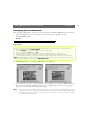
Typical Image Styles
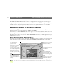
Because the look and feel of the AXIS 2400/2401 user interface is set up by your Administrator(s),
the images format and page styles can vary considerably. Typical layout styles are featured below but these examples should not be interpreted as an exhaustive library of available style formats.
Typical Quad Image Style
Typical Single Image Style
35
36
Using the Video Server
AXIS 2400/2401 Administration Manual
Disconnected Video Sources
All Disabled or Disconnected video cameras are displayed with an appropriate text message in
single-display viewing areas; that is, when a source other than VIDEO ALL is specifically selected.
A blank display - without text, may indicate a break in the signal transmission; such incidents
should be escalated to your system administrator immediately.
Positional Control of the Video Sources
Video cameras supporting Pan Tilt and Zoom (PTZ) control can be attached and positioned
directly from the supported serial ports (COM 1 and COM 2).
Furthermore, the AXIS 2400/2401 can control up to two external (standalone) PTZ devices for
positioning fixed cameras on your system.
All PTZ devices can be steered via the AXIS 2400/2401 Web interface, or TCP application if your
Administrator chooses.
Using the Pan Tilt and Zoom Toolbars
Clicking a specific Video button, other than Video All, automatically displays pan-tilt-configured
video sources in a single-image format that features Pan, Tilt and Zoom bars, as shown below:
Select Preset Position
Zoom
To enable quick and
accurate camera
positioning, the
Administrator can define
within server memory, up
to 20 preset camera
positions. Presets positions
are established and saved as
named entities by your
Administrator and can be
re-established at any time
from the drop-down dialog.
Allows smooth or stepped
camera zoom between
telescopic and wide viewing.
Pan
Allows smooth or stepped
horizontal panning of the
camera. For details, refer to
Camera Positioning
(below).
Click-in-image
For navigational control of
pan tilt devices
Tilt
Allows smooth or stepped
vertical panning of the
camera. For details, refer to
Camera Positioning (below).
Home
Returns the camera to the
default ‘home’ position. For
details, refer to Camera
Positioning (below).
Note: Pan Tilt control can be disabled by your Administrator and unavailable from the user interface.
AXIS 2400/2401 Administration Manual
Using the Video Server
Camera Positioning
Although very similar, the navigational functionality is slightly different for each of the available
pan tilt drivers. The table below describes the basic positioning methods, and the level to which
these are supported by the drivers available from the Administration pages:
Positioning method
Step: Click the left, right, up or down arrows
within the positional toolbar to move the selected
camera in 5o steps (approx) in the chosen direction.
Smooth: Each positional toolbar represents the full
viewing angle for the selected camera.
Click anywhere along the toolbar to gently travel the
camera to its equidistant position.
Click in picture: Click directly in the picture to
define the central position of the selected camera.
Home: Click to move the camera to its home
position, as defined by the pan tilt device.
Diamond
Smartscan
Sony
Canon
Videmech Ernitec Pelco
Yes
Yes
Yes
Yes
Yes
Yes
Yes
Yes
Yes
Yes
No
No
Yes
Yes
Yes
Yes
No
No
Yes
Yes
Yes
Yes
No
No
Camera Zoom
In a fashion similar to that provided for positional control, the degree of camera zoom is controlled
by clicking a scaled toolbar that represents the full tele-zoom potential for the selected device.
Click the left or right arrows within the toolbar for stepped increases for Wide and Tele zoom
respectively. Clicking anywhere along the toolbar gently adjusts the level of camera zoom by a
variable value predetermined by the device.
Note: Variable zoom control is not supported by the Pelco and Ernitec drivers.
Assuming Preset Positions
To enable quick and accurate camera positioning to known camera hotspots, the Administrator(s)
can create up to twenty Preset Positions that can be reinstated at any time by the users.
Choosing a preset position from the drop-down dialog immediately causes the selected camera to
assume the predefined orientation.
37
38
Appendix A - Troubleshooting
AXIS 2400/2401 Administration Manual
Appendix A - Troubleshooting
This appendix provides useful information to help you to resolve any difficulty you might have
with your AXIS 2400/2401. Fault symptoms, possible causes and remedial actions are provided
within a quick reference table.
The Log File
The AXIS 2400/2401 log file records events within the unit and can prove a useful diagnostic tool
when attempting to resolve any problems that might occur.
If you cannot resolve your problem after reading the information in this appendix or by referring to
the AXIS 2400/2401 FAQ, you can escalate the problem to the AXIS support desk. To help us
resolve your problems expediently, please ensure to provide the following information:
• A brief description of the problem
• The log file
• The config file
• If relevant, an example of a poor image
See “Support Services” on page 2 for information on how to contact your local support center.
Obtaining the File
Follow the instructions below to display all Video Server commands executed since the last Restart
of the system:
1. Click the Video Server icon in the graphic interface.
2. Click the View Log File button. All Video Server commands executed since the last Restart of
the system are displayed in a separate window.
Alternatively, obtain a copy of the log file, by typing the following command directly into the
location/Address field (URL) of your Web browser:
http://<servername>/log/messages
AXIS 2400/2401 Administration Manual
Appendix A - Troubleshooting
Examining the File
The Log file can be examined directly using any text editor and typically contains the following
information:
Wed Jun 30 19:13:10 Info: Initialize video decoders
Wed Jun 30 19:13:15 Info: Initialize serial ports and device Drivers
Wed Jun 30 19:13:15 Info: Create Canon VC-C3, COM1
Wed Jun 30 19:13:15 Info: Create HTTP Generic, COM2
Wed Jun 30 19:13:15 Info: Prepare for FTP/CRON image access
Wed Jun 30 19:13:15 Info: Initialize Juliette chip
Wed Jun 30 19:13:15 Info: Start script
Wed Jun 30 19:13:15 Info: Start SoftWatchdog
Wed Jun 30 19:13:15 Info: Create camera device port connection
Typical AXIS 2400/2401 Log File
PINGing Your IP Address
By sending a packet to the specified address and waiting for a reply, the PING (Packet Internet
Groper) can determine whether a specific IP address is accessible; it also provides a particularly
useful method for confirming addressing conflicts with your AXIS 2400/2401 on the network.
Having disconnected your AXIS 2400/2401, follow the instructions below in association with
Symptoms, Possible Causes and Remedial Actions, on page 40, and run the PING utility to
troubleshoot TCP/IP problems on your network:
1. Start a DOS window.
2. Type ping x.x.x.x, where x.x.x.x is the IP address of the AXIS 2400/2401.
3. The subsequent replies will provide an explanation as to the cause of the problem. Replies can
be interpreted as defined in the table below:
PING Reply
Interpretation and recommendation
bytes = 32 time = 2 ms......
The IP address is already used and cannot be used again.
You must obtain a new IP address.
destination host unreachable
The AXIS 2400/2401 is not accessible within your subnet.
You must obtain a new IP address.
request timed out
This IP address is not used by anyone and is available for use with
your AXIS 2400/2401.
39
40
Appendix A - Troubleshooting
AXIS 2400/2401 Administration Manual
Symptoms, Possible Causes and Remedial Actions
Symptoms
Possible causes
Remedial actions
The AXIS 2400/2401 can- The IP address is already 1. Disconnect your AXIS 2400/2401 from the network.
not be accessed from a
used by another device.
2. Run the PING utility (as described in PINGing Your IP
Web browser.
Address, on page 39) and follow the appropriate
recommendations.
Note: The assigned IP number can be assumed valid if the
PING utility returns “request timed out” - in which case you
should set the IP address again, power on the AXIS
2400/2401 and then try accessing the unit again.
The IP address is located Run the PING utility (as described inPINGing Your IP
within a different subnet. Address, on page 39). If the utility returns “no response” or
similar, the diagnosis is probably correct -you should then
proceed as follows:
In Windows 95/98 or Windows NT, check that the IP
address for your AXIS 2400/2401 is within the same subnet
as your workstation:
1. Click "Start", "Settings", "Control Panel" and "Network".
2. Specify the TCP/IP adapter and click on “Properties”. In
Properties, click "IP Address".
3. Check that the first 3 numbers within the IP address of
your AXIS 2400/2401 matches the first 3 of your
workstation. If not, your AXIS 2400/2401 may be on a
different subnet and the IP address cannot be set from
this workstation. You must set the IP address for the
AXIS 2400/2401 from a workstation on the same subnet.
In Windows 95, the ARP
table was empty when
you tried to set the IP
address.
In Windows 95, the ARP command cannot be used if you
have an empty ARP table.
A programming script
locking the unit.
Restore the unit to the factory default default settings. For
details, refer to Reinstating the Factory Default Settings, on
page 25.
Type arp -a to view the ARP table. If it is empty, you must
ping an existing unit on your network before you can download the IP address to the AXIS 2400/2401, using ARP.
See also the Important Note, on page 15. An alternative is
to use the AXIS IP Installer.
The programming script is The programming script is Check that the programming script has been enabled.
not working.
disabled.
The Power indicator is not Faulty power supply.
constantly lit
Verify that you are using an Axis PS-D power supply.
AXIS 2400/2401 Administration Manual
Symptoms
The Network indicator
displays red.
Possible causes
Faulty cabling.
Appendix A - Troubleshooting
Remedial actions
1. To verify that the cables are functional, PING the address
of a known existing unit on your network.
2. If the cabling is OK and your network is reachable, you
should receive the reply similar to this:
...bytes = 32 time = 2 ms,
The Active and Network
indicators are flashing
every 0.5 seconds
Your AXIS 2400 works
locally, but not externally.
No image using Refresh
and/or
Slow updating of
snapshots using the
Server push function.
Triggering difficulties with
programming scripts
Hardware failure.
Contact your Axis dealer.
Firewall protection
Check the Internet firewall with your system manager.
Default routers required
Check if you need to configure the default router settings.
The Internet site is too
heavily loaded.
Use a script running on your web server to relay images
from the AXIS 2400/2401 to the Internet.
Complex images, i.e.
those containing great
picture contrasts, have
greater file size and thus
place greater demand on
the available file space
within the AXIS
2400/2401.
Unable to triggering on
both positive and negative
transitions of the Control
Button and/or IO ports
(double-edged triggering).
The memory constraints become significantly more acute if
multiple clients try to access the same snapshot.
Try limiting the number of clients.
Repetitive trigger conditions that occur in quick succession
of one another can be missed. This is because the command initiated by the first trigger event may not have been
fully executed prior to the second event. This scenario is
demonstrated in the illustration below:
Command
Command
?
Command
T1
T2
T3
Time
Trigger
This feature has particular significance when using commands that take a relatively long time to process, e.g. mail
or ftp, especially if they are conjugated with a loop statement. See also Appendix H- The Programming Script.
Bad snapshot images.
Display configured incorrectly on your workstation.
Within Display Properties, configure your display to show at
least 65'000 colors, i.e. at least 16-bit.
Using only 16 or 256 colors on your computer will produce
dithering artifacts in the image.
Note: If you still have a problem after reading this information, please contact your reseller or check the
FAQ on the Axis Website at http://cctv.axis.com.
41
42
Appendix B - Updating the Software
AXIS 2400/2401 Administration Manual
Appendix B - Updating the Software
The AXIS 2400/2401 server software is stored in Flash memory. This memory is provided by a
silicon chip that just like any other ROM device, retains data content even after power is removed.
Flash memory is unique because it allows its data to be erased and re-written. This means that you
can install software updates for your AXIS 2400/2401 as soon as they become available - without
having to replace any parts. New software can be simply loaded into the AXIS 2400/2401 over the
network.
Obtaining Updated Software
The latest version of the AXIS 2400/2401 server software is available free of charge from Axis or
your local distributor. You can obtain this software over the Internet or via anonymous FTP.
Over the Internet
From the http://cctv.axis.com/ link on the AXIS 2400/2401 Welcome Page, follow the “Support
and Services” and then firmware links, or enter http://cctv.axis.com/service/fware.htm directly
within the URL of your Web browser.
Click the Flash firmware and Release Note link to download the file axis2400.exe. This self
extracting archive file unpacks the associated data and text files upon execution. It is recommended
that you save this file in your root directory.
Anonymous FTP
Log in to ftp.axis.com and go to the /pub/axis/software/cam_srv/cam_2400/latest/ directory.
Download the software download the file axis2400.exe. This self extracting archive file unpacks
the associated data and text files upon execution. It is recommended that you save this file in your
root directory.
Upgrading the Software
There are two methods for updating to the AXIS 2400/2401 Flash memory:
•over the network using the AXIS ThinWizard
•over the network using FTP
Upgrading Using the AXIS ThinWizard
AXIS ThinWizard is a tool for locating, managing and upgrading AXIS ThinServer devices,
including AXIS 2400/2401 products. Supplied on the AXIS Online CD and Axis Website, it
enables batch upgrading of several video servers simultaneously and is the recommended method
for upgrading Axis products in TCP/IP networks.
AXIS 2400/2401 Administration Manual
Appendix B - Updating the Software
Before you begin:
You must assign the AXIS 2400/2401 with an IP address, as described in Assigning an IP Address, on page
13, before you can use this upgrading method.
Follow the instructions below to upgrade your video servers using AXIS ThinWizard:
1. Click the Manage Network button in the AXIS ThinWizard main menu.
2. Select a network group from the drop-down list. You can only update the servers that are
included in the selected network group.
3. All AXIS servers included in the network group appear. Click the Firmware button to start the
Upgrade Wizard.
4. Follow the instructions that are presented to you to complete the installation.
For more information about AXIS ThinWizard, refer to the Axis Website at http://www.axis.com/
Upgrading using FTP
Having obtained the upgrade software, install it into the AXIS 2400/2401 by following the
instructions below:
1. Reset the AXIS 2400/2401 by powering it off and then on again.
2. Start an FTP session and log in to the AXIS 2400/2401 as root, using the root password. By
default this is set to pass.
3. Set FTP to binary mode using the command bin.
4. Download the new camera server software to you AXIS 2400/2401 by using the command put
2400_xxx.bin flash, where xxx is the version number for the firmware.
This process takes 30 - 60 seconds. The LEDs will flash slowly during programming.
Note: If you need to force a download, e.g. when rever ting to an older version of software, use the syntax put 2400_xxx.bin FLASH, where xxx is the version number for the firmware.
5. The AXIS 2400/2401 will report “Transfer complete, flash programming finished
OK”, once the programming is complete.
Caution!
In controlled environments, flash memory upgrades provide a very safe method for updating software.
However, flash products can become damaged if the updating operation if not performed correctly.
Your dealer reserves the right to charge for repairs made nece ssary due to incorrect upgrading by the
user.
43
44
Appendix C - Technical Specifications
AXIS 2400/2401 Administration Manual
Appendix C - Technical Specifications
System Requirements - The AXIS 2400/2401 uses the standard Internet TCP/IP suite of
protocols and can be used with most operating systems: Windows 95, 98 and NT as well as
Linux, UNIX, Mac and several others. The only software required is Microsoft Internet Explorer
4.x, or higher (used with Axis’ ActiveX component AXIS Camera Control), or Netscape 4.x or
above.
Installation - Physical network connection using RJ45 twisted pair cable. Installs directly to NTSC
or PAL video cameras using BNC connectors. Use as a standalone system or as an add-on to
existing CCTV systems.
Management - Remote configuration and status using Web-based tools.
Compression - Motion-JPEG, as well as single snapshot JPEG images. User controlled
compression level.
Video Features - Time stamp and text overlay. Color control (B/W or color).
Video Inputs (AXIS 2400) - supports up to four BNC composite video inputs with 75ohm/Hi Z
termination and includes autosensing for NTSC and PAL.
Video Inputs (AXIS 2401) - Supplied as an NTSC or PAL-specific unit allowing single BNC
composite video connection with 75ohm/Hi Z termination.
Video Output (AXIS 2401) - A single video output (VIDEO OUT) terminated with a coax/BNC
connector that allows direct connection of an external monitor.
Networking - 10baseT Ethernet or 100baseTX Fast Ethernet, TCP/IP, HTTP, FTP, SMTP, NTP,
ARP, BOOTP.
General I/O - 4 optical-isolated alarm inputs and 1 output relay (max 24V, 0.1 A) supplied on a
single terminal block connector. Programmable inputs for remote image storage via File Transfer
Protocol (FTP) or E-mail (SMTP), pre/post alarm image storage.
Pre/Post Alarm Buffer - Up to 8 MByte memory available for pre/post alarm image storage.
Serial Connectors - 9 pin D-SUB RS-232 max 230 Kbps, 9 pin D-SUB RS-232 or RS-485/422
max 38.4 Kbps, half duplex
Pan/Tilt/Zoom - PTZ support for remote camera control. Currently supported units and
protocols include: Ernitech ICU 51PA, Sony EVI-G20/21, EVI-D30/31, Canon VC-C3 and
Diamond Smartscan. Future support for other PTZ units.
AXIS 2400/2401 User’s Manual
Appendix C - Technical Specifications
Security - User level password protection.
Operating Conditions: - Temp: 40-125×F (5-50×C), Humidity: 20-80% RHG.
Approvals - EMC: FCC Class A,
Safety: EN 60950, UL, CSA.
:EN 55022/1987,EN50082- 1/1992
Metrics: - Height: 1.7” (4.2 cm), Width: 5.7” (14.5 cm), Length: 8.7” (22.0 cm), Weight: 1.7 lb.
(0.8 kg), excl. psu.
Hardware - ARTPEC-1 compression chip, ETRAX-100, 32 bit RISC, 100 MIPS CPU, 16 Mbyte
RAM, 2 Mbytes FLASH PROM.
Power - 3 alternative power sources: External power supply 12V AC, 9.6 VA (PS-D, included),
9-20V AC, min 10VA, 6-30V DC, min 7W
Complimentary Software - AXIS IP Installer - for quick installation of multiple units, AXIS Thin
Wizard - remote upgrade of multiple Axis units. AXIS Camera Control (Axis’ ActiveX
component software required for Microsoft Internet Explorer)
ThinServer Technology - Incorporating Axis ThinServer Technology, the AXIS 2400/2401
comprises: “thin” versions of the most popular network operating systems, Web management
tools, Axis’ own ETRAX 32-bit RISC processor - based on open architecture, streamlined and
optimized for device connectivity independent of any file server; and the industry's first dedicated
digital video surveillance compression chip - the AXIS ARTPEC-1.
Performance - The AXIS 2400/2401 delivers the following filesizes:
NTSC
Resolution
PAL
Filesize (kb)
Max fps*
Resolution
Filesize (kb)
Max fps*
704 x 480**
7 - 150
10
704 x 576**
8.5 - 180
8
352 x 240
1.4 - 40
30
352 x 288
1.7 - 50
25
176 x 112
0.3 - 10
30
176 x 144
0.4 - 12
25
Quad (4 x 352 x 240)
7 - 150
5***
Quad (4 x 352 x 288)
8.5 - 180
5***
* Maximum performance given single user and only one video source in use.
** Interlaced image
*** Quad image, images from all four video sources integrated into one single image (AXIS 2400
only).
All specifications are subject to change without prior notice.
45
46
Appendix D - The RS232 Interface
AXIS 2400/2401 Administration Manual
Appendix D - The RS232 Interface
As a complement to the information provided in Pan Tilt Settings, on page 32, this appendix
discusses the functionality of the RS232 serial interface and provides detailed instructions on how
to install a standalone Pan/Tilt device to the AXIS 2400/2401 Video Server.
Two 9 pin D-sub connectors provide the physical connection for the RS232 serial interface of the
AXIS 2400/2401. These connectors are provided for connecting accessory equipment; typically
standalone Pan/Tilt devices for remote positioning of connected video cameras.
The Physical Connector
A diagram of an RS232 connector and the AXIS 2400/2401 pin assignment table are detailed
below.
Pin
COM1
Function
COM2
Function
1
NC
CD
2
- RXD
- RXD
3
- TXD
- TXD
4
RTS
DTR
5
GND
GND
6
DSR
DSR
7
RTS
RTS
8
NC
CTS
9
NC
RI
5
4
9
3
8
2
7
1
6
Notes: The pinout is different for each supported serial por t
NC = Not connected
Camera Positioning
The AXIS 2400/2401 can control the position of connected cameras in three different ways:
• Pan Tilt Control using the Web Administration Tools: where, the position of the selected video
camera is controlled using a standard Web browser.
• Generic Control using CGI parameters: enter the positioning data as a CGI command directly
into your Web browser Location/Address (URL).
• Generic control using a TCP client: using a TCP client-application to control the position of
the chosen camera.
AXIS 2400/2401 Administration Manual
Appendix D - The RS232 Interface
Installing Pan/Tilt Devices
The diagram below illustrates how the AXIS 2400/2401 connects to your workstation, video
cameras and relative Pan Tilt Device. ➀ A fixed camera can be positioned remotely by using an
External Pan Tilt device. ➁ A PTZ-supported camera is connected directly to the COM 1 or
COM 2 ports directly.
Fixed
Camera
Computer
1
Web Browser
Administration Tools
RS232
Pan Tilt
Device Driver
COM 1
Camera
RS485
RS232
AXIS 2400
COM 2
External
Pan Tilt
Device
Pan Tilt
Device
2
Follow the instructions below to install a Pan/Tilt device:
1. Attach the Pan/Tilt device to the Pan/Tilt port of the AXIS 2400/2401 using an RS232 cable.
Note: It is also possible to connect a Pan Tilt device via the RS485 por t. See Appendix F - The IO Terminal Block for details.
2. On the AXIS 2400/2401 Home Page, click Settings. You will be prompted to supply a
username and password. By default, these are set to root and pass.
3. Click Pan/Tilt.
4. Click Driver. Select the driver that corresponds to your Pan/Tilt device from the drop-down
menu. Click Store driver.
47
48
Appendix D - The RS232 Interface
AXIS 2400/2401 Administration Manual
Supported Pan Tilt Drivers
A comprehensive list of currently supported drivers with their associated settings is provided below:
Driver
Diamond Smartscan
(SCAN III Family)
Canon VC C3
Accommodates single device
connection only - per RS232
port.
Sony G20/G21/D30/D31
(VISCA)
Accommodates up to three
devices connected in
daisy-chain.
Videmech
(Universal Outstation
Communication Protocol)
Up to four devices connect to
the RS485 connector in the
terminal block.
Ernitec ERNA
Up to four devices connect to
the RS485 connector in the
terminal block.
Pelco Digital Coaxitron
Up to four devices connect to
the RS485 connector in the
terminal block.
Serial Settings
Baud = 9600
Parity = Even
Databits =8
Stopbits=1
Baud = 9600
Parity = None
Databits =8
Stopbits=2
Driver Specific Settings
Define the unit identity, corresponding to the DIP switch settings
for the connected device(1-255).
Baud = 9600
Parity = None
Databits =8
Stopbits=1
AXIS 2400 only: Define the unit identity, corresponding the
order in which the device is connected in the daisy chain.Note:
Sony devices normally support automatic sensing and
chronological assignment of device identities for daisy-chain
configurations.
Baud = 9600
Parity = Odd
Databits =8
Stopbits=1
Define the following:
None.
•
Serial Address: the address of the head connected to the
camera corresponding to the DIP switch settings for the connected device(1-255). Note: the address 255 is reserved for
broadcast, i.e all connected heads will receive commands
sent to this address.
•
Movement limits: the limits representing the end positions in
all directions; i.e left, right, up and down. These limits ensure
that head travel is kept within certain bounds and must be
used if there is any risk of obstruction in the device head
movement.
•
Zoom and focus limits: indicating the end position for focus
and zoom. In order not to stall the motors when approaching
the mechanical end positions of your lens, it is very important that you limit the wide/tele intervals in accordance with
the physical travel restrictions for the lens mechanism.
•
Zoom and focus enabled: uncheck these boxes if you not
using a zoom and/or focus lens.
•
Optical Data: the MaxDeg setting should correspond to the
optimal width of the viewing angle at max wide; the MinDeg
setting should correspond to the minimal viewing angle at
max tele.
Baud = 2400
Parity = None
Databits =8
Stopbits=1
Define the unit identity, corresponding to the DIP switch settings
for the connected device(1-255).
Baud = 2400
Parity = None
Databits =8
Stopbits=1
Define the unit identity, corresponding to the DIP switch settings
for the connected device(1-255).
AXIS 2400/2401 Administration Manual
Appendix D - The RS232 Interface
Important!
Although many of the supported drivers have been tested and found to work satisfactorily with the
AXIS 2400/2401, Axis cannot guarantee the compatibilty of all drivers, conforming or otherwise, to a
specific manufacturer’s protocol.
Notes: •Setting the Pan Tilt Address to 255 causes the control signals to be broadcast to all connected
devices.
•Check the user documentation supplied with your Pan Tilt device for detailed information.
Generic Serial Port Control using HTTP
The AXIS 2400/2401 supports input/output operations on the serial ports via the HTTP protocol.
The functionality can be used for adjusting the video camera position or for controlling a simple
device, such as a relay switch. The schematic diagram below illustrates the logical elements for such
a configuration:
Fixed
Camera
Computer
1
Web Browser
CGI Parameters
RS232
HTTP Driver
Device Driver
COM 1
Camera
RS485
RS232
AXIS 2400
COM 2
External
Pan Tilt
Device
Pan Tilt
Device
2
Follow the instructions below to configure serial port control for use with the HTTP protocol:
1. Click the Generic icon within the graphic user interface.
2. Set the HTTP radio button.
3. Click Save.
The Pan/Tilt port is now enabled for input/output operations via HTTP.
49
50
Appendix D - The RS232 Interface
AXIS 2400/2401 Administration Manual
Serial Port Control using the TCP Protocol
The AXIS 2400/2401 supports input/output operations on the serial ports directly via the TCP
protocol. The functionality can be used for adjusting the video camera position or for controlling a
simple device, such as a relay switch. This functionality is normally used from a client application,
developed for instance in Visual Basic. The schematic diagram below illustrates the logical elements
for such a configuration:.
Fixed
Camera
Computer
1
TCP Application
e.g. Visual Basic
RS232
TCP Driver
Device Driver
COM 2
External
Pan Tilt
Device
COM 1
Camera
RS485
RS232
AXIS 2400/2401
Pan Tilt
Device
2
To enable TCP input/output operations on the Pan/Tilt port, follow these steps:
1. Click the Generic icon within the graphic user interface.
2. Set the TCP radio button.
3. Define the appropriate TCP Port number.
4. Click Save.
Note: Your TCP client application must also use this TCP port when communicating with the AXIS
2400/2401.
5. The Pan/Tilt port is now enabled for input/output operations via TCP.
Tip!
In step 3 (above), use a Telnet session to access the TCP port, and set a null modem connection to a
terminal program; such as, Hyper Terminal to verify the setup of the generic TCP driver.
AXIS 2400/2401 User’s Manual
Appendix E - CGI Parameters
Appendix E - CGI Parameters
The Common Gateway Interface (CGI) is a standard for interfacing external applications with
information servers, such as a Web server. A CGI program within the AXIS 2400/2401 allows you
to define special video image features within an embedded URL request and generate simple
HTTP input/output operations for controlling the Pan/Tilt port.
CGI parameter requests are generated in the form of query strings appended to the URL of the
AXIS 2400/2401.
CGI Parameters for Image Requests
For snapshot requests, use this syntax:
http://<servername>/cgi-bin/<imagefile>?<parameter>=<value>[&<parameter>=<value>...]
This table lists the CGI parameters for snapshot requests:
Parameter/Syntax
Description
Values
Selects the source for
camera=<n>
generating snapshots. If
(applicable for AXIS
1,2,3 or 4
omitted, the default camera is
2400 only)
used.
1-5, where:
compression=
Adjusts the image quality and 1= minimum, 2=low,
3=medium, 4=high,
<value>
file size.
5=very high
1 or 2; where:
color=<value>
Selects color or grayscale.
1=grayscale, 2=color
clock=<value>
Shows/hides the time stamp. on, off
Shows motion JPEG image
motion=<n>
0
stream
Example 1
Request a fullsize JPEG snapshot from the default camera connected to the AXIS 2400/2401
videoserv that contains a clock reference:
http://videoserv/cgi-bin/fullsize.jpg?clock=on
Example 2
Request a highly compressed hugesize JPEG snapshot from the camera connected to VIDEO 2
on an AXIS 2400 with the DNS name videoserv:
http://videoserv/cgi-bin/hugesize.jpg?camera=1&compression=5
51
52
Appendix E - CGI Parameters
AXIS 2400/2401 Administration Manual
Example 3
The following example features a simple JavaScript that transmits live video images from a
AXIS 2400/2401 into a Web page, using Netcape:
<html>
<head>
<title>Live Video Demo for Netscape</title>
</head>
<body>
<H2>Live Video Demo for Netscape</H2>
<IMG SRC="http://172.21.1.200/cgi-bin/fullsize.jpg?camera=1&motion=0">
</body>
</html>
Example 4
The following example features a JavaScript that transmits live video images from a AXIS
2400/2401 into a Web page, using either Netcape or Microsoft Internet Explorer:
<html>
<head>
<title>Live Video Demo, Netscape and Microsoft Internet Explorer</title>
</head>
<body>
<H2>Live Video Demo, Netscape and Microsoft Internet Explorer</H2>
<SCRIPT LANGUAGE="JavaScript">
<!--//hide script
if ((navigator.appName ==
"Microsoft Internet Explorer") &&
(navigator.platform != "MacPPC") &&
(navigator.platform != "Mac68k"))
{
document.write("<OBJECT ID=\"CamImage\" WIDTH=352 ");
document.write("HEIGHT=288 CLASSID=CLSID:917623D1-")
document.write("D8E5-11D2-BE8B-00104B06BDE3 CODEBASE=");
document.write("\"http://172.21.1.200/activex/ATLCamImage.ocx");
document.write("#Version=1,0,1,18\"> <PARAM NAME=\"URL\" ");
document.write("VALUE=\"http://172.21.1.200/cgi-bin/fullsize.jpg");
document.write("?motion=10&camera=1\">");
document.write("</OBJECT>");
}
else
{
document.write("<IMG SRC=\"http://172.21.1.200");
document.write("/cgi-bin/fullsize.jpg?camera=1&motion=0\"");
}
//end hide -->
</SCRIPT>
</body>
</html>
AXIS 2400/2401 User’s Manual
Appendix E - CGI Parameters
CGI Parameters for Pan Tilt and Zoom Control
Use the following syntax for creating CGI parameters to control Pan Tilt devices:
http://<servername>/cgi-bin/control?camera=<n>&<parameter>=<value>[&<parameter>=<value>...]
Example
Move the camera connected to VIDEO 1 on videoserv 45 degrees to the right:
http://videoserv/cgi-bin/control?camera=1&pan=45
This table lists the CGI parameters for Pan Tilt requests:
Parameter/Syntax
camera=<n>
move=<x>
*pan=<n>
*tilt=<n>
*rpan=<n>
*rtilt=<n>
Description
Selects the source for pan tilt requests. This is
mandatory and must be submitted (for the AXIS
2401this is always set to 1).
Moves the Pan/Tilt device 5 degrees in the
specified direction.
Pans the Pan/Tilt device <n> degrees relative to
the home position.
Tilts the Pan/Tilt device <n> degrees relative to
the home position.
Pans the Pan/Tilt device <n> degrees relative to
the current position.
Tilts the Pan/Tilt device <n> degrees relative to
the current position.
*zoom=<n>
Adjusts the camera zoom to the specified angle.
zoomrel=<x>
*focus=<x>
*focusrel
Adjusts zoom to specified values.
Adjusts zoom within the specified scale.
Adjusts zoom to upper and lower extremes.
Assumes the camera position defined by the
preset position number.
Assumes the camera position defined by the
preset position name.
Sets the head speed of the pan tilt device
connected to the selected camera/port.
identifies the type of pan tilt driver connected to
the selected camera/port.
presetposno
presetposname=<name>
*speed=<n>
whoami
Values
1,2,3 or 4
up/down/left/right/upleft/upright/
downleft/downright/*home/
-180 ... 180
-180 ... 180
-180 ... 180
-180 ... 180
1 ... 999
where 1is full zoom out
wide/tel/*widemax/*telemax/
1 ... 999
far or near
1 ... 20
<name>
1 ... 999
check
Notes: •Parameters and values identified with an asterisk “*” are not available to all supported pan tilt
devices. For the latest driver-specific information, check out the Axis Camera Developer’s Web
at http://cctv.axis.com/
•The CGI parameters that adjust the camera position are only applicable when using one of the
suppor ted Pan/Tilt devices.
53
54
Appendix E - CGI Parameters
AXIS 2400/2401 Administration Manual
CGI Parameters for Preset Positions
For preset position requests, use this syntax:
http://<servername>/cgi-bin/control?presetposname=<position name>&camera=<n>
It is also possible to use an index number instead of the preset position name:
http://<servername>/cgi-bin/control?presetposno=<1-20>&camera=<n>
CGI Parameters for Serial Port Control
For HTTP input/output operations on the Pan/Tilt port requires the Generic driver to be selected.
Use the following syntax:
http://<servername>/cgi-bin/control?<parameter>=<value>[&<parameter>=<value>...]
This table lists the CGI parameters for input/output operations
Parameter/Syntax
dataout=<string>
port = <n>
read=<n>
wait=<n>
flush=<value>
Description
Writes a specified data string to the
defined serial port (see port
parameter, below). Maximum string
length = 128 bytes.
Selects the serial port as either
COM1 or COM2. This is mandatory
and must be submitted.
Reads the specified number of bytes
from the Pan/Tilt port. The returned
value will be hexadecimal coded
and placed between #’s, e.g. #3A#.
Waits the specified number of
seconds before reading from the
Pan/Tilt port. Used together with the
“read” parameter.
Empties the input buffer for the
Pan/Tilt port. Always performed first
when combined with other
parameters.
Values
Hexadecimal coded
bytes {0, 1, 2, 3, 4, 5, 6,
7, 8, 9, A, B, C, D, E, F,
a, b, c, d, e, f}
1 or 2
1 ... 128
1 ... 9
yes/no
AXIS 2400/2401 User’s Manual
Appendix E - CGI Parameters
Example 1
Writes the data stream 430001FF to COM1:
http://videoserv/cgi-bin/control?port=1&dataout=430001FF
Example 2
Clears the input buffer, writes the data string 2B004C4C4F to COM1 and waits 5 seconds for a
reply. The AXIS 2400/2401 will return a value to the Web browser:
http://videoserv/cgi-bin/control?port=1&flush=yes&dataout=2B004C4C4F&wait=5&read=20
Example 3
An HTML page for reading and writing to the COM1 serial port:
<html>
<head>
<title>HTTP Input/Output Test Page</title>
</head>
<body>
<h2>HTTP Input/Output Test Page</h2>
<form action="http://videoserv/cgi-bin/control" method=post>
Write hexadecimal byte string
<input type=hidden name="port" value="1">
<input type=text size=20 maxsize=19 name="dataout"> to COM1
<p>Read <input type=text size=4 name="read" value="0"> bytes from COM1</p>
<p>Wait <input type=text size=4 name="wait" value="1"> seconds</p>
<input type=submit name="send" value="Send HTTP Request">
</form>
</body>
</html>
In a Web browser, the page will look like this:
55
56
Appendix F - The IO Terminal Block
AXIS 2400/2401 Administration Manual
Appendix F - The IO Terminal Block
Typically used in association with programming scripts for developing applications for motion
detection, event triggering, time lapse recording, alarm notification via e-mail, picture storage to
FTP locations and a variety of other functions; the 16-pin IO Terminal Block is located on the rear
panel and provides the interface to: a single relay switch output, four digital photo-coupled inputs,
an RS 485 interface, and auxiliary power.
This appendix describes the pinout, interface support and the
control and monitoring functions provided by this connector.
1 2 3 4 5 6 7 8
Note: Appendix H- The Programming Script supplements the information provided within this section and is recommended reading
for developers wanting to fully utilize the control and monitoring functions suppor ted by this connector.
9 10 11 12 13 14 15 16
Connector Pinout
The pinout for the Terminal Block (illustrated left) and signaling details for each pin is fully
described in the table below:
Pin
Function
Description
1
Auxiliary AC Power Input
2
Auxiliary AC Power Input
Electrically connected in parallel with PS-D power connector, pins 1 &
2 provide an auxiliary connector for mains power to the unit.
3
Digital Input 3 - Photocoupler Anode (+)
4
Digital Input 3 - Photocoupler Cathode (-)
Photocoupled Input 3: Electrically isolated from the chassis and connectors, this input can be supplied from an external DC voltage or
the DC Power Input/Output on pins 9 and 10.
5
Digital Input 4- Photocoupler Anode (+)
Photocoupled Input 4. As above.
6
Digital Input 4 - Photocoupler Cathode (-)
7
RS 485 - B (inverting)
8
RS 485 - A (non-inverting)
9
DC + Power (Input or Output)
10
DC - Power (Input or Output)
11
Digital Input 1 - Photocoupler Anode (+)
12
Digital Input 1 - Photocoupler Cathode (-)
13
Digital Input 2 - Photocoupler Anode (+)
14
Digital Input 2 - Photocoupler Cathode (-)
15
Relay Switch
16
Relay Switch
Serial Port1- RS485. A half duplex RS485 interface for controlling
auxiliary equipment. Note: Serial Port 1 is programmed as either
RS232 (COM1 Connector) or RS485 (Terminal Block Connector), via
the Web browser interface.
DC Power Input or Output: Used as an input, it supplies the Axis
2400 via a DC source; for example. a solar panel or a battery.
As an output, it can drive the photo coupler inputs or other equipment; such as an IR-sensor. The output voltage level is dependent
upon the input voltage to the unit. A maximum current of 50mA can
be sourced from the DC output.
Pin 10 is connected to unit chassis, and Ground on each serial port
and video input. See circuit diagram (below).
Input 1 Photo coupler input. As Input 3.
Input 2 Photo coupler input. As Input 3.
Relay switch - electrically isolated from chassis and connectors.
AXIS 2400/2401 Administration Manual
Appendix F - The IO Terminal Block
Note: For compatible replacement connectors, contact http://www.phoenixcontact.com, quoting:
MC1.5/8-ST-3.81 (ar t no 1803633)
Power and Ground
AXIS 2400/2401
3.3V
z
z
Switch
Mode
Power
Supply
z
~
z
z
Internal
o PS-D
o
o1
z
z z
z
z
o2
~
o9
+
o 10
-
z
z
z
GND PIN 5 z
o COM 1
z
z
GND PIN 5 z
o COM 2
z
GND.
z
z
z
z
z
VIDEO 1
VIDEO 4
57
58
Appendix F - The IO Terminal Block
AXIS 2400/2401 Administration Manual
Controlling and Monitoring
The status of the input/output interface can be controlled and monitored by the IO software file
resident within your AXIS 2400/2401.
From your Web browser, you can access the IO control file to:
• query the relay status, or drive the relay output high or low
• monitor the status of the 4 digital inputs
Note: To access the control file requires root access, you will therefore need to supply a username and
password. Login as root and supply the root password (default = pass).
Relay Output
You can use the supported relay output to drive directly a maximum load of 24V AC/DC at
100mA. By connecting additional relay circuitry, it can also drive heavier loads.
Querying the Status of the Relay
Enter the following URL to query the status of the relay output:
http://<servername>/io?relay=check
The AXIS 2400/2401 displays the relay status as either:
relay=on or
relay=off
Setting the Relay
The relay can be controlled from the scripting language using the relay command, as described in
relay, on page 75, or by entering the following URL:
http://<servername>/io?relay=on or
http://<servername>/io?relay=off
The AXIS 2400/2401 returns a respective messages, to confirm the relay status:
Relay is off
Relay is on
AXIS 2400/2401 Administration Manual
Appendix F - The IO Terminal Block
Digital Inputs
The four digital inputs make it possible to trigger your snapshots on chosen events using a
programming script. By connecting a motion detector to a digital input for example, it is possible
to trigger picture storage for each occasion that the detector is activated.
For full programming information, please refer to Appendix H- The Programming Script.
1
~ o2
~o
9
+ o
-
o
o
12V AC
o
o
AXIS 2400/2401
Switch, motion detector, etc.
10
o
o 11
o 12
o 13
+
o 14
-
Industrial
Control
Device
o 15
Relay
Switch
Optional
Relay
Switch
o
o
o
o
Appliance
ox
o 16
oo
24V DC
RS485 A
RS485 B
o
o
8
7
oo
Mains Power
o
PTZ Camera
Schematic diagram of the AXIS 2400/2401 Auxiliary Connector
- displaying a possible application
59
60
Appendix F - The IO Terminal Block
AXIS 2400/2401 Administration Manual
Querying the Status of Digital Inputs
The status of the four supported digital inputs can be queried in exactly the same fashion as the
relay output. Simply enter the following URL to query the status of the digital inputs:
http://<servername>/io?relay=check
The AXIS 2400/2401 displays the relay status as either:
Input1
Input2
Input3
Input4
is on / off
is on / off
is on / off
is on / off
AXIS 2400/2401 Administration Manual
Appendix G - Camera Applications
Appendix G - Camera Applications
The AXIS 2400/2401 offers live video over the network for enhancing and modernizing traditional
CCTV and video surveillance systems... and much more.
Whereas traditional security systems often limit camera access to a specific monitor; the AXIS
2400/2401 allows industrial and security surveillance over a secure intranet network and even
allows you to broadcast live images over the Internet. You can now monitor operations remotely
from within the comfort of your own home, corporate headquarters; or indeed, from any
workstation of your choosing that supports a Web browser. Just think... no more late trips to the
factory to investigate problems!
This section provides a detailed description of each preconfigured application available within the
Layout and Configuration Wizard and several client application ideas that will be of interest to
Administrators developing their own applications.
Wizard Preconfigurations
There are currently two Layout and Preprogramming applications available. The Application
Wizard guides you through the configuration procedure and helps you to define the functionality
of your application and general look-and-feel of the user interface. You initially choose from
Surveillance System or Web Attraction preconfigurations and then refine the application
specifically to your needs by selecting from several of the available features in the Wizard.
Surveillance System - Provides a typical surveillance design; including: Quad system with or
without pre/post alarm storage, Pan Tilt Zoom control and preset, variable picture size and
magnification parameters. Aesthetic aspects of system presentation; such as, background, logo, user
button and product title presentation, are also configurable.
Web Attraction - A basic system design that delivers a standard picture system - without the
alarm and control features provided by of the former. Aesthetic aspects of system presentation; such
as, background, logo, user button and product title presentation, are configurable.
61
62
Appendix G - Camera Applications
AXIS 2400/2401 Administration Manual
Client Applications
Aside from the preconfigured applications included as standard in the AXIS 2400/2401; there are a
whole host of other exciting applications that have already been developed, tested and
implemented by other developers using Axis’ camera products.
Typical applications include: security surveillance in banks, parking lots and conference rooms,
industrial surveillance, visual security systems, medical applications, intruder alarm verification,
traffic surveillance, image archiving, integrating video images into personal Web application using
CGI scripts, fun applications etc. SMTP e-mail support means that you can even send images as
e-mail attachments at predetermined times or events.
Notes: •Take the time to look at what other organizations in the industry are doing with Axis’ network
cameras. Visit Axis’ dedicated CCTV Website at: http://cctv.axis.com
•Network Camera Ser vers Developer’s Pages: The Camera Division at Axis maintain a specialist
site for network camera developers. New exciting application ideas, tools, and pre-programming scripts are constantly being added - this is an invaluable reference site for Axis’ development partners and OEMs. Follow the camera links and check it out at: http://cctv.axis.com/
AXIS 2400/2401 Administration Manual
Appendix H-The Programming Script
Appendix H- The Programming Script
Administrators and developers wishing to create a special level of customization within their
applications can create their own programming scripts using the Programming Script Editor.
Using the programming scripts demonstrated in this appendix, you can quickly develop
applications for: motion detection, event triggering, alarm notification via e-mail, picture storage to
FTP locations and a whole host of other functions limited only by your imagination.
The programming syntax and option information is supported by practical examples presented
within the context of genuine scripts that have been developed, tested and implemented into
proper user applications.
Note: Network Camera Servers Developer’s Pages: The Camera Division at Axis maintain a specialist
site for network camera developers. New exciting application ideas, tools, and programming
scripts are constantly being added to provide an invaluable reference site for Axis’ development
par tners and OEMs. Follow the camera links and check it out at: http://cctv.axis.com/
Starting and Enabling the Editor
1. Click the Programming Script Editor button to start the editor.
2. Enter a your script in the main window and then click the Save button to deposit the script in
product memory.
3. Check the Enable box to activate the programming scripts in your system.
Notes: •Scripts can be saved but are not activated until the Enabled button is checked.
•Saving new scripts automatically removes any existing script previously saved with the Editor.
•A previously saved script is automatically displayed when the Programming Script Editor is
opened.
Programming Script Format
A programming script for the AXIS 2400/2401includes one or several entries and is entered into
the editor in the following format:
# <comments>
<triggering condition> :
<commands>;
%
63
64
Appendix H-The Programming Script
AXIS 2400/2401 Administration Manual
where:
• The <comments> are optional.
• The <trigger condition> includes the following fields: <minute> <hour> <day> <month>
<weekday> <optional input/boot event>
• The <commands> include one or several programming script commands.
Comments
It is good programming practice to start each new entry with a comment to describe its function.
Comments are optional but must be proceeded by a # character, as detailed below:
# <comment>
Example:
# This programming entry will...
Trigger Condition
The commands contained within each specific entry are triggered by a defined trigger condition.
The trigger condition is specified by six separate fields and must be terminated with a colon “:”.
<Minute> <Hour> <Day> <Month> <Day of the week> <Input and Boot Field (optional)> :
Time and Date Event Fields
The first five fields specify the time and date events, i.e. Minute, Hour, Day, Month and Day of
the week.
The syntax for each field within a trigger condition is governed by the following rules:
• Each time and date field can contain several numerical event variables that are delimited by
commas and hyphens.
• Each field is delimited by an open space.
• An asterisk (*) represents the full range of event variables within the relative time and date field,
i.e. * * * * * means every minute, every hour, every day, every month, every day of the week.
• Numerical event variables separated by a hyphen indicate an inclusive range; for example, 2-6
means 2 to 6.
Example:
Trigger every month, between the fourth and eighth at 10.03, 12.03 and 14.03, using the 24-hour
clock:
3 10,12,14 4-8 * * :
AXIS 2400/2401 Administration Manual
Appendix H-The Programming Script
Input and Boot Field
The sixth field is an optional Input and Boot field that defines the input and boot trigger functions.
Using the trigger variables boot, B, I1 and I2 respectively, you can program the AXIS
2400/2401 to trigger at startup or on the logical states present on the Control button and digital
input ports. The B, I1 and I2 trigger variables must be proceeded by an activate condition, /, \, 0
or 1, to indicate when the trigger variable is activated.
Note: The AXIS 2400/2401 has four digital input ports 1 - 4 interfaced via the Terminal Block Connector. For connection details please refer to Appendix F - The IO Terminal Block.
The table below outlines the available trigger variables and their possible combinations:
Trigger Variable
Description
BOOT
Activate at startup.
START
Activate at startup and when a new script is compiled
\V
Activate when one enabled video signal is lost
/V
Activate when all enabled video signals are back
\B
Activate after high-low logical transition of Control button.
/B
Activate after low-high logical transition of Control button.
1B
Activate when Control button is logically high (pressed).
0B
Activate when Control button is logically low (released).
\I1
Activate after high-low logical transition on Input Port 1.
/I2
Activate after low-high logical transition on Input Port 2.
1I1
Activate when Input Port 1 is logically high.
0I2
Activate when Input Port 2 is logically low.
... etc.
Note: The video server polls the input por ts every 0.2 seconds. Thus, more rapid logical transitions will
not be detected.
Complex triggering mechanisms can be developed by simply conjugating the trigger variables using
a logical AND function (&), as shown below.
Example 1
Activate on Control button transition from high to low and Input port 1 high.
\B&1I1
Example 2
Activate on Input port 1 low and Input port 2 transition from low to high.
0I1&/I2
65
66
Appendix H-The Programming Script
AXIS 2400/2401 Administration Manual
Commands
A comprehensive catalog of available programming commands, complete with their syntax and
valid options are described below:
alert
The alert command sends a message to a remote host.
Syntax
alert [-host HOST] [-port PORTNUMBER] [-message STRING];
Options
-host Specifies the host name or IP address of the remote host.
-port Specifies the TCP port number in the range [0..65534].
-message
Specifies the message that will be sent to the remote host. The message must be surrounded
by quotation marks. Hexadecimal coded messages must be preceded by \0x, e.g. "\0x04" for
the non-printed character EOT. To include a quotation mark, it must be preceded by a
backslash, e.g. \".
Example
# This command will send the message "Alarm
# "0013" from AXIS 2400" to the remote host when
# input port 1 goes high.
* * * * * /I1:
alert -host 172.21.1.202 -port 2703 -message "Alarm \"0013\" from AXIS 2400";
%
buffer_init
The buffer_init command initiates or clears the image buffers. This is needed in order to store
images using the buffer_start and buffer_stop commands.
Syntax
buffer_init [[CAMERANUMBER],[IMAGE],[SIZE][:[CAMERANUMBER],[IMAGE],[SIZE]]];
Options
CAMERANUMBER
Specifies the camera source, i.e. 1- 4 (AXIS 2401must be set to 1)
IMAGE
Specifies the image type 1- 3, where: 1=halfsize.jpg, 2=fullsize.jpg and 3=hugesize.jpg
AXIS 2400/2401 Administration Manual
Appendix H-The Programming Script
SIZE
Specifies the maximum number of images that can be stored in the buffer. The valid range is
0-65535, although in practice is limited by the amount of available memory within the
AXIS 2400/2401.
To initiate several buffers, you can stack multiple statements separated by colon.
Notes: •To clear the image buffer, you simply do not specify any arguments.
•To initiate several buffers, you can stack multiple statements. Each statement must separated by
a colon “:”.
Example 1
# At startup, this command will initiate one
# buffer for camera 1 with 25 fullsize.jpg images
# and one buffer for camera 2 with 5 hugesize.jpg
# images.
* * * * * BOOT:
buffer_init 1,2,25:2,3,5;
%
Example 2
# This command will clear the buffer every Sunday.
00**0*:
buffer_init;
%
buffer_start
The buffer_start command stores snapshots in a specific image buffer. Before the command can
be used, the buffer facility must be initiated using the buffer_init command.
When invoked, the buffer_start command is executed in the background and any subsequent
command in the event entry is executed immediately.
Images are retrieved using the ftp or mail command (refer to page 70 and page 73 respectively).
Syntax
buffer_start [-src SOURCEFILE] [-cam CAMERANUMBER]
[-interval TIME] [-duration TIME] [-store SIZE];
Options
-src Specifies the source file name, i.e. halfsize.jpg, fullsize.jpg or hugesize.jpg.
-cam Specifies the camera source, i.e. 1-4. If omitted, the default camera will be used (AXIS
2401must be set to 1)
67
68
Appendix H-The Programming Script
AXIS 2400/2401 Administration Manual
-interval
Specifies the time interval between consecutive snapshots. If omitted, new snapshots are
generated without any delay.
Format: h<hours>m<minutes>s<seconds>, or fps <approximate frames per
second>.
-duration
Specifies the total time for the command to run. If omitted, the buffer_start command will
be issued only once.
Format: h<hours>m<minutes>s<seconds>.
If you specify -duration inf, the command will continue to be executed until it is
interrupted by any of the commands: buffer_init, buffer_start or buffer_stop.
-store
Specifies the number of images to be stored in the buffer. This setting will override the
duration. The maximum number of images is specified by the buffer_init command.
Example
# This command will keep loading fullsize.jpg images.
******:
buffer_start -src fullsize.jpg -cam 3 -interval s30
-duration inf;
%
buffer_stop
The buffer_stop command terminates the storage of snapshots to an image buffer. Until
completed, the buffer_stop command will block the execution of any subsequent commands in the
event entry. Note that the buffer_start command behaves differently.
The command is typically used together with the buffer_start command.
Syntax
buffer_stop [-src SOURCEFILE] [-cam CAMERANUMBER]
[-interval TIME] [-duration TIME] [-store SIZE];
Options
-src Specifies the source file name, i.e. halfsize.jpg, fullsize.jpg or hugesize.jpg.
-cam Specifies the camera source, i.e. 1- 4. If omitted, the default camera will be used.
-interval
Specifies the time interval between consecutive snapshots. If omitted, new snapshots will be
generated without any delay.
Format: h<hours>m<minutes>s<seconds>, or fps <approximate frames per
second>.
AXIS 2400/2401 Administration Manual
Appendix H-The Programming Script
-duration
Specifies the total time for the command to run. If omitted, the buffer_start command will
be issued only once.
Format: h<hours>m<minutes>s<seconds>.
Note that if you specify -duration inf, the command will continue to be executed until it
is interrupted by a buffer_init command.
-store
Specifies the number of images to be stored in the buffer. This setting will override the
duration. The maximum number of images is specified by the buffer_init command.
Example
# This command initiates the buffer to hold 60
# halfsize.jpg and 5 hugesize.jpg images. New images
# are captured until the buffer_start command is
# interrupted.
* * * * * BOOT :
buffer_init 1,1,60:1,3,5;
buffer_start -src halfsize.jpg -interval s1 -duration inf;
buffer_start -src hugesize.jpg -interval m1 -duration inf;
%
# When port 1 is triggered, an alert message is sent
# to host 1.2.3.4. Another 10 halfsize.jpg images are
# captured and all the images are sent to an ftp
# server with the names "Halfsize_1" to
# "Halfsize_60". Then the buffer is restarted.
* * * * * /I1:
alert -host 1.2.3.4 -port 4000 -message "Alert! Input on port 1.";
buffer_stop -src halfsize.jpg -store 10;
ftp -host somehost -user USER -pass PASS -src images/buffer.jpg -dest
Halfsize_$r1-60 -time
h1 -buffer halfsize.jpg;
alert -host 1.2.3.4 -port 4000 -message "Alert! Images sent to ftp server";
%
# When port 2 is triggered, the 5 most recent
# hugesize.jpg images are sent to an ftp server
# with the names "Picture_1" to "Picture5". Note that
# the buffer is not stopped.
* * * * * /I2:
ftp -host somehost -user USER -pass PASS -src images/buffer.jpg -dest
Picture_$r1-5 -time h1
-buffer hugesize.jpg;
%
69
70
Appendix H-The Programming Script
AXIS 2400/2401 Administration Manual
ftp
The ftp command uses the standard File Transfer Protocol (FTP) for transferring an image from
your AXIS 2400/2401 to a remote host.
Note: The ftp command keeps the connection open during each file transfer.
Syntax
ftp
[-host HOST] [-user USERNAME] [-pass PASSWORD]
[-src SOURCEFILE] [-dest DESTINATIONFILE]
[-temp TEMPORARY_DESTINATION_NAME] [-loop LOOPTIME]
[-time TOTALTIME] [-cam CAMERANUMBER]
[-buffer BUFFERTYPE];
Options
-host Specifies the name or IP address of the remote host. If specifying the DNS name,
performance will be slightly decreased due to the DNS lookup. If no host is specified, the
compiler will complain.
-user Specifies the user name for logging on to the remote host. If no user name is specified, the
compiler will complain.
-pass Specifies the password for logging on to the remote host.
-src Specifies the source file name. If omitted, the fullsize.jpg file will be sent. To include
the image buffer, specify images/buffer.jpg.
-dest Specifies the name and whole path of the destination file. If omitted, the destination file
name will be the same as the source file name. The maximum length of a destination file
name is 255 characters. You can add as many destination files as required, separated by a
space.
You can add time stamps, such as time, date and file indexes, to the destination file name.
This is useful for example when you are transferring a series of files.
The following table lists the available time stamp variables. Every substitution must be
proceeded by a dollar sign “ $”.
$s
The current second in the range 00-59.
$m
The current minute in the range 00-59.
$h
The current hour in the range 00-23.
AXIS 2400/2401 Administration Manual
Appendix H-The Programming Script
$d
The current day of the month in the range 01-31.
$n
The current month in the range 01-12.
$y
The current year without the century in the range 00-99.
$Y
The current year including the century.
$rS-E
-temp
-loop
-time
-cam
Inserts an index number starting from number S through all the numbers including the
number E. If you leave out number E, it will be interpreted as a very large number.
Note: The rS-E substitution can be used with the first destination file only.
Specifies a temporary name for the destination. This is to prevent someone else from
accidentally reading the file during the download.
Specifies the time interval within which the command should be repeated and used together
with the time attribute. If omitted, there will be no delay between repeated transfers.
Format: h<hours>m<minutes>s<seconds>, or fps <approximate frames per
second>. Optional.
Specifies the total time the command should loop. Used
together with the loop attribute. If omitted, the ftp command will be issued only once.
Format: h<hours>m<minutes>s<seconds>. Optional.
Specifies the camera source, i.e. 1 - 4. If this is omitted, video camera source 1 is used as
default.
-buffer
Specifies the buffer type, e.g. fullsize.jpg, halfsize.jpg or hugesize.jpg. Only valid
if -src is set to images/buffer.jpg.
Additional Options
In addition to the options described above, the following optional settings are also available:
-ctrlport
Specifies the TCP port number in the range [0..65534] to be used as the control port for the
FTP server.
-dataport
-to
Specifies the TCP port number in the range [0..65534] to be used as data port for the FTP
server.
Specifies the timeout, i.e. the FTP session will terminate when the specified time limit has
expired. Format: h<hours>m<minutes>s<seconds>.
71
72
Appendix H-The Programming Script
AXIS 2400/2401 Administration Manual
Example 1
# This command will log in as "user" with the
# password "pass" on the host with the Internet
# address 123.123.123.123, download a hugesize
# image with the name "user.jpg" and put
# it in the directory "/home/user" on the remote
# host. During download, the file name "tmp.jpg"
# will be used.
******:
ftp -host 123.123.123.123 -user user -pass pass
-src hugesize.jpg -dest /home/user/user.jpg -temp
tmp.jpg;
%
Example 2
# This command will every hour, every five seconds
# for twenty minutes, download a fullsize image
# from camera 3 and save the images with a time
# stamp in the filename.
0*****:
ftp -host an.interesting.site -user user -pass pass -src fullsize.jpg
-dest tmp/full$h$m$s.jpg -loop s5 -time m20 -cam 3;
%
Example 3
# This command will send 1001 consecutive fullsize
# images to "your.host.name". The first and last
# images will be named "fullsize1000.jpg" and
# "fullsize2000.jpg", respectively.
******:
ftp -host your.host.name -user user -pass pass
-src fullsize.jpg -dest
/home/camera1/tmp/fullsize$r1000-2000.jpg;
%
AXIS 2400/2401 Administration Manual
Appendix H-The Programming Script
log
This command writes a message to the AXIS 2400/2401 log file.
Note: To display the log file, you type the following in the address/location field of your Web browse r:
http://<video server>/log/messages
Syntax
log [MESSAGE];
Options
[MESSAGE]
The message string must be surrounded by quotation marks.
Example:
# This command writes a message to the log file when the AXIS 2400/2401Control Button is pressed.
* * * * * /B :
log "The Control button was pressed." ;
%
mail
This command uses the Simple Mail Transfer Protocol (SMTP) for sending images and files from
your AXIS 2400/2401 to e-mail addresses.
Note: The IP address of the mail server and a valid return address on the TCP/IP page must be specified when using the mail command.
Syntax
mail [-s SUBJECT] [-a ATTACHMENTS] [-t RECIPIENTS]
[-cam CAMERANUMBER] [-b BUFFERTYPE] [-n NUMBER];
Options
Specifies the subject text for the e-mail. A simple one-word subject does not require
-s
quotation marks. A subject with multiple words must be surrounded by quotation marks.
Specifies attachments such as images or files.To include the image buffer, specify:
-a
images/buffer.jpg.
Specifies the e-mail address of the recipient(s).
-t
-cam Specifies the camera source, i.e. 1-4. If omitted, the default camera will be used (AXIS 2401
must be set to 1).
Specifies the buffer type, i.e. fullsize.jpg, halfsize.jpg or hugesize.jpg. Only valid
-b
if -a is set to: images/buffer.jpg.
73
74
Appendix H-The Programming Script
-n
AXIS 2400/2401 Administration Manual
Specifies the number of buffered images to be included in the e-mail. Only valid if -src is set
to images/buffer.jpg.
Example 1
# This command will send an e-mail with the
# subject "Hello" and the attached file
# fullsize.jpg to [email protected]
******:
mail -s Hello -a fullsize.jpg -t [email protected];
%
Example 2
# This command will send an e-mail with the
# subject "This "fullsize.jpg" was sent from my
# AXIS 2400" to two recipients.
******:
mail -s "This \"fullsize.jpg\" was sent from my AXIS 2400" -a fullsize.jpg -t
[email protected] [email protected];
%
Example 3
# This command will send an e-mail with two attachments.
******:
mail -a fullsize.jpg halfsize.jpg -t me@home;
%
ptz
This command pans, tilts and zooms connected video cameras.
Syntax
ptz [-speed VALUE[DEVICE]][-preset POSITION]
[-cam CAMERANUMBER][-zoom VALUE][-move DIRECTION]
[-pan ANGLE][-tilt ANGLE];
Options
-speed
Supported by Canon and Sony drivers only, this parameter defines within the range 1 - 999,
the speed with which the camera source moves between the defined positions; where: 1 is
slow and 999 is fast.
AXIS 2400/2401 Administration Manual
Appendix H-The Programming Script
-preset
-cam
-zoom
-move
-pan
-tilt
Specifies the preset position, i.e. 1- 20. Note that camera source must be defined within the
command.
Specifies the camera source, i.e. 1 - 4. If this is omitted, video camera source 1 is used as
default (AXIS 2401 must be set to 1).
Specifies the zoom value of the selected camera source, i.e. 1 - 999.
Note that this option is device dependent and is supported by Sony, Canon and Videmech
drivers only.
Specifies in which direction the selected camera source shall be moved, i.e. home, up, upleft,
left, downleft, down, downright, right, upright. Note that the move home option is only
supported by the drivers Sony, Canon and Videmech.
Specifies the pan angle of the selected camera source,
i.e. -180 - 180. Note that this option is device dependent and is supported by the drivers
Sony, Canon and Videmech.
Specifies the tilt angle of the selected camera source,
i.e. -180 - 180. Note that this option is device dependent and is supported by the drivers
Sony, Canon and Videmech.
Example 1
# This command moves camera 1 up five degrees and zooms wide.
******:
ptz -cam 1 -zoom 1 -move up;
%
Example 2
# This command moves camera 1 to preset position 1.
******:
ptz -preset 1 -cam 1;
%
Note: The options must be entered in the following orde r:
-speed, -preset, -cam, -zoom, -move, -pan, -tilt
For example; ptz -tilt 10 -cam 4, will not work. You must enter, ptz -cam 4 -tilt 10.
relay
This command sets the relay on or off within the AXIS 2400/2401.
Syntax
relay [-on | -off];
75
76
Appendix H-The Programming Script
AXIS 2400/2401 Administration Manual
Options
-on
sets the relay on.
-off
sets the relay off.
Example
# This command sets the relay ON when digital input 1 goes high:
* * * * * / I1 :
reset -on;
%
reset
This command resets the software or hardware of the AXIS 2400/2401.
Syntax
reset [-soft | -hard];
Options
-soft Reinitiates the AXIS 2400/2401 protocols.
-hard Performs a complete reboot of the AXIS 2400/2401.
Example
# This command will reset the hardware once a day.
00****:
reset -hard;
%
sleep
This command adds a pause to the programming script execution. The command is typically used
if you want to assure that the previous command is finished before continuing the script.
Syntax
sleep <seconds>;
Options
<seconds>
Specifies the seconds to wait before proceeding with the next command in the event entry.
Example
# This command will result in a 30 seconds pause in the programming script execution.
******:
sleep 30;
%
AXIS 2400/2401 Administration Manual
Index
Index
A
Administration tools 19
alert, Programming script 66
Anonymous user access 24
ARP 13, 15, 40
AXIS IP Installer 13
AXIS Online CD 11
AXIS ThinWizard 42
B
bad snapshot images 41
BOOTP 13, 16
buffer_init, Programming script 66
buffer_start,Programming script 67
buffer_stop, Programming script 68
C
Camera applications 61
CGI Parameters
input/output operations 54
preset positions 54
Compression 28
Configuration
FTP 33
configuration
administration 19
Configuring 18
Control Button 9
D
Digital inputs 59
DIP Switches 9
DNS server 27
Driver Specific Settings 48
E
Ethernet address 13
F
Factory Default Settings 25
FAQ’s - Frequently asked questions 7
FTP 33
ftp, Programming script 70
I
I/O Terminal Block 10
Internet address 40
IO files 58
IP address 13
L
log
Programming script 73
Log file 38
examining 39
obtaining 38
M
mail
Programming script 73
N
Network Connector 10
Network Indicator 9
Network indicator 41
O
Obtaining updated software 42
anonymous FTP 42
over the internet 42
OS/2 15
P
Pan/Tilt 46, 47
connection 46
Parameter list
defaults 25
performance 45
PING command 15
poor images 41
Positioning 37
Power Indicator 9
Power indicator 40
Power Supply Connector 10
Preset Positions 37
problems 38, 51
Programming
alert 66
77
78
Index
Programming script
buffer_init 66
buffer_start 67
buffer_stop 68
commands 66
format 63
ftp 70
Input and Boot 64, 65
log 73
mail 73
ptz 74
reset 75, 76
sleep 76
Time and Date 64
Trigger 64
trigger condition 64
ptz
Programming script 74
Q
Quad Image 35
R
RARP 13, 16
relay output 56, 58
Reload/Refresh 17
reset, Programming script 75, 76
RS232 connector
diagram 46
RS-232 Serial Connectors 10
RS232 serial interface 46
S
serial interface 46
Serial Number 9
Serial Settings 48
Server password 19
Server push 41
Single Image 35
sleep, Programming script 76
Status Indicator 9
T
technical specifications 44
time stamp
Programming script 70
triggering snapshots 59
troubleshooting 38, 51
AXIS 2400/2401 Administration Manual
U
UNIX 15
Upgrading the software
using FTP 43
V
Video Inputs 8
Video Output 8
W
Welcome page 17
Z
Zoom 37