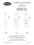
1
550-867
Betriebsanleitung
Service
Instructions
Foreword
This instruction manual is intended to help the user to become familiar
with the machine and take advantage of its application possibilities in
accordance with the recommendations.
The instruction manual contains important information on how to
operate the machine securely, properly and economically. Observation
of the instructions eliminates danger, reduces costs for repair and
down-times, and increases the reliability and life of the machine.
The instruction manual is intended to complement existing national
accident prevention and environment protection regulations.
The instruction manual must always be available at the machine/sewing
unit.
The instruction manual must be read and applied by any person that is
authorized to work on the machine/sewing unit. This means:
–
–
–
Operation, including equipping, troubleshooting during the work
cycle, removing of fabric waste,
Service (maintenance, inspection, repair) and/or
Transport.
The user also has to assure that only authorized personnel work on the
machine.
The user is obliged to check the machine at least once per shift for
apparent damages and to immediatly report any changes (including the
performance in service), which impair the safety.
The user company must ensure that the machine is only operated in
perfect working order.
Never remove or disable any safety devices.
If safety devices need to be removed for equipping, repairing or
maintaining, the safety devices must be remounted directly after
completion of the maintenance and repair work.
Unauthorized modification of the machine rules out liability of the
manufacturer for damage resulting from this.
Observe all safety and danger recommendations on the machine/unit!
The yellow-and-black striped surfaces designate permanend danger
areas, eg danger of squashing, cutting, shearing or collision.
Besides the recommendations in this instruction manual also observe
the general safety and accident prevention regulations!
General safety instructions
The non-observance of the following safety instructions can cause
bodily injuries or damages to the machine.
1. The machine must only be commissioned in full knowledge of the
instruction book and operated by persons with appropriate training.
2. Before putting into service also read the safety rules and
instructions of the motor supplier.
3. The machine must be used only for the purpose intended. Use of
the machine without the safety devices is not permitted. Observe all
the relevant safety regulations.
4. When gauge parts are exchanged (e.g. needle, presser foot, needle
plate, feed dog and bobbin) when threading, when the workplace is
left, and during service work, the machine must be disconnected
from the mains by switching off the master switch or disconnecting
the mains plug.
5. Daily servicing work must be carried out only by appropriately
trained persons.
6. Repairs, conversion and special maintenance work must only be
carried out by technicians or persons with appropriate training.
7. For service or repair work on pneumatic systems, disconnect the
machine from the compressed air supply system (max. 7-10 bar).
Before disconnecting, reduce the pressure of the maintenance unit.
Exceptions to this are only adjustments and functions checks made
by appropriately trained technicians.
8. Work on the electrical equipment must be carried out only by
electricians or appropriately trained persons.
9. Work on parts and systems under electric current is not permitted,
except as specified in regulations DIN VDE 0105.
10. Conversion or changes to the machine must be authorized by us
and made only in adherence to all safety regulations.
11. For repairs, only replacement parts approved by us must be used.
12. Commissioning of the sewing head is prohibited until such time as
the entire sewing unit is found to comply with EC directives.
13. The line cord should be equipped with a country-specific mains
plug. This work must be carried out by appropriately trained
technicians (see paragraph 8).
It is absolutely necessary to respect the safety
instructions marked by these signs.
Danger of bodily injuries !
Please note also the general safety instructions.
Index
Page:
Preface and General Safety Instructions
Service Instructions Class 550-867
(Edition 12/2011)
1
1.1
1.2
1.3
General notes
Gauges. . . . . . . . . . . . . . . . . . . . . . . . . . . . . . . . . . . . . . . . . . . . . . . . . . . . .
Description of the locking positions . . . . . . . . . . . . . . . . . . . . . . . . . . . . . . . . . . .
Graduation on the handwheel . . . . . . . . . . . . . . . . . . . . . . . . . . . . . . . . . . . . . . .
2
2.1
2.2
2.2.1
2.2.2
2.3
2.3.1
2.3.2
2.3.3
2.3.4
2.3.5
2.3.6
2.4
2.5
2.5.1
2.5.2
2.6
2.6.1
2.6.2
2.6.4
2.6.5
2.7
2.7.1
2.7.2
2.7.3
2.8
2.8.1
2.8.2
2.8.3
2.9
2.9.1
2.9.2
2.9.3
2.10
Sewing machine
Position of the arm shaft crank on the arm shaft . .
Upper and lower toothed belt wheel / toothed belt
Position of the upper toothed belt wheel . . . . . .
Position of the lower toothed belt wheel. . . . . . .
Bottom feed and stepping motor . . . . . . . . . . .
Pre-setting . . . . . . . . . . . . . . . . . . . . . . . .
Position of the feed dog in the throat plate cutout.
Feeding motion of the feed dog . . . . . . . . . . . .
Lifting motion of the feed dog . . . . . . . . . . . . .
Feed dog height . . . . . . . . . . . . . . . . . . . . .
Balance weight . . . . . . . . . . . . . . . . . . . . . .
Transmission lever . . . . . . . . . . . . . . . . . . . .
Needle bar linkage . . . . . . . . . . . . . . . . . . . .
Align the needle bar linkage laterally . . . . . . . . .
Needle penetration in feeding direction . . . . . . .
Hook, looping stroke and needle bar height . . . .
Looping stroke . . . . . . . . . . . . . . . . . . . . . .
Needle bar height . . . . . . . . . . . . . . . . . . . .
Distance between hook and needle . . . . . . . . .
Needle guard . . . . . . . . . . . . . . . . . . . . . . .
Bobbin case opening . . . . . . . . . . . . . . . . . .
General . . . . . . . . . . . . . . . . . . . . . . . . . .
Setting of the bobbin case opening . . . . . . . . .
Timing of opening . . . . . . . . . . . . . . . . . . . .
Feeding foot and presser foot . . . . . . . . . . . . .
Feeding foot and presser foot stroke. . . . . . . . .
Stroke motion of the feeding foot . . . . . . . . . . .
Sewing foot pressure . . . . . . . . . . . . . . . . . .
Sewing foot lifting . . . . . . . . . . . . . . . . . . . .
Mechanical sewing foot lifting . . . . . . . . . . . . .
Height of the sewing feet arrested with hand lever
Height of the lifted sewing feet . . . . . . . . . . . .
Thread-guiding parts . . . . . . . . . . . . . . . . . .
.
.
.
.
.
.
.
.
.
.
.
.
.
.
.
.
.
.
.
.
.
.
.
.
.
.
.
.
.
.
.
.
.
.
.
.
.
.
.
.
.
.
.
.
.
.
.
.
.
.
.
.
.
.
.
.
.
.
.
.
.
.
.
.
.
.
.
.
.
.
.
.
.
.
.
.
.
.
.
.
.
.
.
.
.
.
.
.
.
.
.
.
.
.
.
.
.
.
.
.
.
.
.
.
.
.
.
.
.
.
.
.
.
.
.
.
.
.
.
.
.
.
.
.
.
.
.
.
.
.
.
.
.
.
.
.
.
.
.
.
.
.
.
.
.
.
.
.
.
.
.
.
.
.
.
.
.
.
.
.
.
.
.
.
.
.
.
.
.
.
.
.
.
.
.
.
.
.
.
.
.
.
.
.
.
.
.
.
.
.
.
.
.
.
.
.
.
.
.
.
.
.
.
.
.
.
.
.
.
.
.
.
.
.
.
.
.
.
.
.
.
.
.
.
.
.
.
.
.
.
.
.
.
.
.
.
.
.
.
.
.
.
.
.
.
.
.
.
.
.
.
.
.
.
.
.
.
.
.
.
.
.
.
.
.
.
.
.
.
.
.
.
.
.
.
.
.
.
.
.
.
.
.
.
.
.
.
.
.
.
.
.
.
.
.
.
.
.
.
.
.
.
.
.
.
.
.
.
.
.
.
.
.
.
.
.
.
.
.
.
.
.
.
.
.
.
.
.
.
.
.
.
.
.
.
.
.
.
.
.
.
.
.
.
.
.
.
.
.
.
.
.
.
.
.
.
.
.
.
.
.
.
.
.
.
.
.
.
.
.
.
.
.
.
.
.
.
.
.
.
.
.
.
.
.
.
.
.
.
.
.
.
.
.
.
.
.
.
.
.
.
.
.
.
.
.
.
.
.
.
.
.
.
.
.
.
.
.
.
.
.
.
.
.
.
.
.
.
.
.
.
.
.
.
.
.
.
.
.
.
.
.
.
.
.
.
.
.
.
.
.
.
.
.
.
.
.
.
.
.
.
.
.
.
.
.
.
.
.
.
.
.
.
.
.
.
.
.
.
.
.
.
.
.
.
.
.
.
.
.
.
.
.
.
.
.
.
.
.
.
.
.
.
.
.
.
.
.
.
.
.
.
.
.
.
.
.
.
.
.
.
.
.
.
.
.
.
.
.
.
.
.
.
.
.
.
.
.
.
.
.
.
.
.
.
.
.
.
.
.
.
.
.
.
.
.
.
.
.
.
.
.
.
.
.
.
.
.
.
.
.
.
.
.
.
.
.
.
.
.
.
.
.
.
.
.
.
.
.
.
.
.
.
.
.
.
.
.
.
.
.
.
.
.
.
.
.
.
.
.
.
.
.
.
.
.
.
.
.
.
.
.
.
.
.
.
.
.
.
.
.
.
.
.
.
.
.
.
.
.
.
.
.
.
.
.
.
.
.
.
.
.
.
.
.
.
.
.
.
.
.
.
.
.
.
.
.
.
.
.
.
.
.
.
.
.
.
.
.
.
.
.
.
.
.
.
.
.
.
.
.
.
.
.
.
.
.
.
.
.
.
.
.
.
.
.
.
.
.
.
.
.
.
.
.
.
.
.
.
.
.
.
.
.
.
.
.
.
.
.
.
.
.
.
.
.
.
.
.
.
.
.
.
.
.
.
.
.
.
.
.
.
.
.
.
.
.
.
.
.
.
.
.
.
.
.
.
.
.
.
.
.
.
.
.
.
.
.
.
.
.
.
.
.
.
.
.
.
.
.
.
.
.
.
.
.
.
.
.
.
.
.
.
.
.
.
.
.
.
.
.
.
.
.
.
.
.
.
.
.
.
.
.
.
.
.
.
.
.
.
.
.
.
.
.
.
.
.
.
.
.
.
.
.
.
.
.
.
.
.
.
.
.
.
.
.
.
.
3
4
5
6
7
7
8
9
9
10
12
13
14
15
16
17
17
18
19
19
20
21
22
23
23
23
25
26
26
27
28
29
29
30
31
32
Index
Page:
2.10.1
2.10.2
2.10.3
2.10.4
2.11
2.11.1
2.11.2
2.11.3
2.11.4
2.11.5
2.12
2.13
2.13.1
2.13.2
2.14
2.15
Thread regulator . . . . . . . . . . . . . . . . . . . . . . . . . . .
Thread take-up spring. . . . . . . . . . . . . . . . . . . . . . . .
Thread tension plate. . . . . . . . . . . . . . . . . . . . . . . . .
Measuring system for thread tension. . . . . . . . . . . . . . .
Short thread cutter. . . . . . . . . . . . . . . . . . . . . . . . . .
General . . . . . . . . . . . . . . . . . . . . . . . . . . . . . . . .
Locking latch for the thread-pulling knife . . . . . . . . . . . .
Thread pulling knife . . . . . . . . . . . . . . . . . . . . . . . . .
Counter knife . . . . . . . . . . . . . . . . . . . . . . . . . . . . .
Cutting position . . . . . . . . . . . . . . . . . . . . . . . . . . .
Important notes concerning electrostatic discharges (ESD) .
Potentiometer in the arm . . . . . . . . . . . . . . . . . . . . . .
Basic setting without control panel . . . . . . . . . . . . . . . .
Basic setting with the control panel V810 or V820 . . . . . . .
Connections on the PCB . . . . . . . . . . . . . . . . . . . . . .
Setting the sliding clutch . . . . . . . . . . . . . . . . . . . . . .
.
.
.
.
.
.
.
.
.
.
.
.
.
.
.
.
32
33
34
34
35
35
36
37
39
41
42
43
43
44
45
46
3
3.1
3.2
Oil lubrication
Hook lubrication . . . . . . . . . . . . . . . . . . . . . . . . . . . . . . . . . . . . . . . . . . . . . . .
Maintenance . . . . . . . . . . . . . . . . . . . . . . . . . . . . . . . . . . . . . . . . . . . . . . . . .
48
49
4
4.1
4.1.1
4.1.2
4.1.3
4.1.4
4.2
4.3
4.4
4.5
4.6
4.6.1
4.6.2
4.6.3
4.6.4
4.7
4.8
4.9
4.10
4.11
4.12
4.13
4.13.1
4.13.2
4.13.3
Setting of the tearing seam visualization software
General . . . . . . . . . . . . . . . . . . . . . . . . . . . .
Security levels . . . . . . . . . . . . . . . . . . . . . . . .
Data backup . . . . . . . . . . . . . . . . . . . . . . . . .
Accessing the system for the first time . . . . . . . . .
Logging in with scanner and barcode . . . . . . . . . .
Exiting the system . . . . . . . . . . . . . . . . . . . . . .
Setting a new operator . . . . . . . . . . . . . . . . . . .
Deleting an operator. . . . . . . . . . . . . . . . . . . . .
Displaying an operator . . . . . . . . . . . . . . . . . . .
Seam patterns . . . . . . . . . . . . . . . . . . . . . . . .
Creating a new seam pattern . . . . . . . . . . . . . . .
Editing a seam pattern . . . . . . . . . . . . . . . . . . .
Copying a seam pattern . . . . . . . . . . . . . . . . . .
Deleting a seam pattern . . . . . . . . . . . . . . . . . .
Database . . . . . . . . . . . . . . . . . . . . . . . . . . .
Check . . . . . . . . . . . . . . . . . . . . . . . . . . . . .
Error codes . . . . . . . . . . . . . . . . . . . . . . . . . .
Determining the end label barcode . . . . . . . . . . . .
Determining the end label layout . . . . . . . . . . . . .
Adapting barcode definitions . . . . . . . . . . . . . . .
Setting the printer . . . . . . . . . . . . . . . . . . . . . .
Uninstall the printer driver . . . . . . . . . . . . . . . . .
Install a new printer . . . . . . . . . . . . . . . . . . . . .
Printer calibration . . . . . . . . . . . . . . . . . . . . . .
.
.
.
.
.
.
.
.
.
.
.
.
.
.
.
.
.
.
.
.
.
.
.
.
.
.
.
.
.
.
.
.
.
.
.
.
.
.
.
.
.
.
.
.
.
.
.
.
.
.
.
.
.
.
.
.
.
.
.
.
.
.
.
.
.
.
.
.
.
.
.
.
.
.
.
.
.
.
.
.
.
.
.
.
.
.
.
.
.
.
.
.
.
.
.
.
.
.
.
.
.
.
.
.
.
.
.
.
.
.
.
.
.
.
.
.
.
.
.
.
.
.
.
.
.
.
.
.
.
.
.
.
.
.
.
.
.
.
.
.
.
.
.
.
.
.
.
.
.
.
.
.
.
.
.
.
.
.
.
.
.
.
.
.
.
.
.
.
.
.
.
.
.
.
.
.
.
.
.
.
.
.
.
.
.
.
.
.
.
.
.
.
.
.
.
.
.
.
.
.
.
.
.
.
.
.
.
.
.
.
.
.
.
.
.
.
.
.
.
.
.
.
.
.
.
.
.
.
.
.
.
.
.
.
.
.
.
.
.
.
.
.
.
.
.
.
.
.
.
.
.
.
.
.
.
.
.
.
.
.
.
.
.
.
.
.
.
.
.
.
.
.
.
.
.
.
.
.
.
.
.
.
.
.
.
.
.
.
.
.
.
.
.
.
.
.
.
.
.
.
.
.
.
.
.
.
.
.
.
.
.
.
.
.
.
.
.
.
.
.
.
.
.
.
.
.
.
.
.
.
.
.
.
.
.
.
.
.
.
.
.
.
.
.
.
.
.
.
.
.
.
.
.
.
.
.
.
.
.
.
.
.
.
.
.
.
.
.
.
.
.
.
.
.
.
.
.
.
.
.
.
.
.
.
.
.
.
.
.
.
.
.
.
.
.
.
.
.
.
.
.
.
.
.
.
.
.
.
.
.
.
.
.
.
.
.
.
.
.
.
.
.
.
.
.
.
.
.
.
.
.
.
.
.
.
.
.
.
.
.
.
.
.
.
.
.
.
.
.
.
.
.
.
.
.
.
.
.
.
.
.
.
.
.
.
.
.
.
.
.
.
.
.
.
.
.
.
.
.
.
.
.
.
.
.
.
.
.
.
.
.
.
.
.
.
.
.
.
.
.
.
.
.
.
.
.
.
.
.
.
.
.
.
.
.
.
.
.
.
.
.
.
.
.
.
.
.
.
.
.
.
.
.
.
.
.
.
.
.
.
.
.
.
.
.
.
.
.
.
.
.
.
.
.
.
.
.
.
.
.
.
.
.
.
.
.
.
.
.
.
.
.
.
.
.
.
.
.
.
.
.
.
.
.
.
.
.
.
.
.
.
.
.
.
.
.
.
.
.
.
.
.
.
.
.
.
.
.
.
.
.
.
.
.
.
.
.
.
.
.
.
.
.
.
.
.
.
.
.
.
.
.
.
.
.
.
.
.
.
.
.
.
.
.
.
.
.
.
.
.
.
.
.
.
.
.
.
.
.
.
.
.
.
.
.
.
.
.
.
.
.
.
.
.
.
.
.
.
.
.
.
.
.
.
.
.
.
.
.
.
.
.
.
.
.
.
.
.
.
.
.
.
.
.
.
.
.
.
.
.
.
.
.
.
.
.
.
.
.
.
.
.
.
.
.
.
.
.
.
.
.
.
.
.
.
.
.
.
.
.
.
.
.
.
.
.
.
.
.
.
.
.
.
.
.
.
.
.
.
.
.
.
.
.
.
.
.
.
.
.
.
.
.
.
.
.
.
.
.
.
.
.
.
.
.
.
.
.
.
.
.
.
.
.
.
.
.
.
.
.
.
.
.
.
.
.
.
.
.
.
.
.
.
.
.
.
.
.
.
.
.
.
.
.
.
.
.
.
.
.
.
.
.
.
.
.
.
.
.
.
.
.
.
.
.
.
.
.
.
.
.
.
.
.
.
.
.
.
.
.
.
.
.
.
.
.
.
.
.
.
.
.
.
.
.
.
.
.
.
.
50
50
51
51
52
53
54
55
56
57
58
63
64
65
66
68
91
92
95
96
100
100
103
110
1
General
The present service instruction describes the adjustment of the
special sewing machine 550-867.
ATTENTION!
The operations described in the service instructions must only be
executed by qualified staff or correspondingly instructed persons
respectively!
Caution: Risk of injury!
In case of repair, alteration or maintenance work turn off the main
switch and disconnect the machine from the pneumatic supply
system.
Carry out adjusting operations and functional tests of the running
machine only under observation of all safety measures and with
utmost caution.
The present service instructions describe the adjustment of the
sewing machine in an appropriate sequence. Please observe in this
connection that various setting positions are interdependent.
Therefore it is absolutely necessary to do the adjustment following the
described order.
For all setting operations of parts involved in the stitch formation a
new needle without damage has to be inserted.
Machine covers having to be screwed off and on again for checking
and adjusting operations are not mentioned in the text.
Note:
Some of the shafts of the special sewing machine 550-867 are
provided with flat spots. This facilitates the adjustment considerably.
In case of all adjustments on flat spots the first screw in rotation
direction is put on such a flat spot.
1.1
Gauges
1
The locking pin 1 required for adjusting the machine belongs to the
serial equipment of the machine. It is in the accessories and can be
put at the bottom side of the oil pan.
3
1.2
Description of the locking positions
3
4
2
1
With the locking pin 1 and the arresting grooves 2 and 3 in the arm
shaft crank 4 the sewing machine can be arrested in two adjusting
positions.
Position I = Locking pin Ø 5 mm for large groove
= Looping stroke, needle bar height
Position II = Locking pin Ø 3 mm for small groove
= Needle bar at its upper dead center, graduation on the
handwheel
4
1.3
Graduation on the handwheel
1
2
3
The handwheel 2 has a graduation printed on it.
Certain settings are carried out according to the position of the
handwheel.
– Turn the handwheel until the degree mark mentioned in the
present instructions points to the index 3.
– Carry out the described adjustment.
Setting the handwheel
– Set the handwheel to the degree mark 50°
– Loosen the threaded pin for the handwheel through opening 1.
– Set the handwheel to 0°
– Arrest the machine in position II with the locking pin Ø 3 mm
– Loosen the threaded pin for the handwheel through opening 1.
– Turn the handwheel 2 so that the degree mark 0° points to the
middle of the index 3.
– Tighten the threaded pin for the handwheel through opening 1.
– Set the handwheel to 50° and tighten the threaded pin for the
handwheel.
5
2
Sewing machine
2.1
Position of the arm shaft crank on the arm shaft
2
4
3
1
2
1
Caution: Risk of injury!
Turn off the main switch.
Check and set the position of the arm shaft crank only when the
machine is switched off.
Standard checking
The arm shaft crank 1 is fastened on the arm shaft 4 with three
threaded pins 2. The threaded pins must sit on the flat spot 3.
Correction
– Loosen the threaded pins 2 on the arm shaft crank.
– Twist the arm shaft crank 1 on the shaft until the threaded pins 2
sit on the flat spot 3.
– Push the arm shaft crank axially to the right as far as it will go.
– Tighten the threaded pins 2.
6
2.2
Upper and lower toothed belt wheel / toothed belt
2.2.1
4
Position of the upper toothed belt wheel
3
2
1
3
2
Caution: Risk of injury!
Turn off the main switch.
Check and set the position of the upper toothed belt wheel only when
the machine is switched off.
Standard checking
The toothed belt wheel 2 is fastened on the arm shaft 4 with two
threaded pins. The threaded pins must sit on the flat spot 1.
The distance between the toothed belt wheel 2 and the bobbin winder
wheel 3 must amount to 0.8 mm when the bobbin winder is switched
off.
– Check distance between toothed belt wheel 2 and bobbin winder
wheel 3 by means of a thickness gauge.
Correction
– Loosen the threaded pins in the toothed belt wheel.
– Turn the toothed belt wheel, until the threaded pins sit on the flat
spot 1 of the arm shaft 4.
– Set lateral distance of 0.8 mm between the toothed belt wheel 2
and the bobbin winder wheel 3 by using a thickness gauge.
– Tighten the threaded pins in the toothed belt wheel.
7
2.2.2
Position of the lower toothed belt wheel
1
5
4
3
2
1
Caution: Risk of injury!
Turn off the main switch.
Check and set the position of the lower toothed belt wheel only when
the machine is switched off.
Standard checking
The threaded pins in the toothed belt wheel 2 must sit on the flat spot
1 of the lower shaft 5.
The toothed belt wheel must be positioned in a way that the toothed
belt 4 bears against the belt tensioner ring 3 when the handwheel is
turned but without being dislocated.
– Check the position of the toothed belt wheel.
Correction
– Pull out the toothed belt from the lower toothed belt wheel.
– Loosen the threaded pins in the toothed belt wheel.
– Turn the toothed belt wheel 2, until the screws sit on the flat spot
of the lower shaft 5.
– Tighten the threaded pins in the toothed belt wheel.
– Mount the toothed belt on the toothed belt wheel.
– Check the course of the toothed belt.
ATTENTION: Danger of breakage!
After replacing the toothed belt, check the following settings: Hook
adjustment (see chapter 2.6), feeding motion of the feed dog (see
chapter 2.3.4) and lifting motion of the feed dog see chapter 2.3.5).
8
2.3
2.3.1
Bottom feed and stepping motor
Pre-setting
1
2
3
4
5
6
7
Caution: Risk of injury!
Turn off the main switch.
Adjust the basic setting only with the sewing machine switched off.
Pre-setting
– Fix the screws 1 and 3 on the flat spots of the shaft 2.
– Loosen screw 4.
– Bring the gear tongues 5 into parallel position and align the
markings 6 and 7.
– Tighten screw 4.
Fine adjustment
(see software chapter 4.14)
9
2.3.2
Position of the feed dog in the throat plate cutout
2
9
8
7
6
5
4
3
14
Caution: Risk of injury!
Turn off the main switch.
Check and set the position of the feed dog and stitch regulator gear
only when the machine is switched off.
–
–
–
–
–
–
–
–
10
11
–
Loosen the threaded pins on the adjustment rings 8 and 9.
Loosen screw 5.
Align the feed dog in the center of the throat plate cutout.
Arrest the shaft 7 with the adjustment rings 8 and 9 and tighten
the screws.
Loosen threaded pin 10 and screw 2.
Loosen the threaded pins on the thrust eccentric 4.
Align the positioning frame 14 laterally so that it comes to sit in the
center between the cutouts on the shaft 7.
Arrest the positioning frame 14 axially with the bearing bolt 6
(fixed with screw 10) and the adjustment ring 2.
Tighten the threaded pins on the thrust eccentric 4.
Note:
The shaft 11 is fixed on surface in the positioning frame 14
at position 3 with two screws in series.
10
11
–
–
–
–
–
–
12
13
Set the lever on the step motor to marking.
Set the gear to “0”.
In order to do so, turn the positioning frame 14 so that the tongues
come parallel to each other.
Tighten the screw 13 on the block 12.
Align the feed dog in longitudinal direction in the center of the
throat plate cutout.
Tighten screw 5 (see picture on page 10).
Fit in the spring 1 (see picture on page 10) on the positioning
frame and the fastening bracket.
ATTENTION: Danger of breakage!
The shaft 11 must not reach so far into the positioning frame 14 that
the tongues are hindered in their movements.
11
2.3.3
Feeding motion of the feed dog
1
Caution: Risk of injury!
Turn off the main switch.
Check and set the feeding motion of the feed dog only when the
machine is switched off.
Standard checking
When the machine is in position “190°” the feed dog must not
move upon actuating the stitch regulator if the maximum
stitch length is set.
– Set the maximum stitch length.
– Turn the machine to position “190°”.
– Move the stitch regulator by switching the step motor from
forwards to backwards stitches and check whether the feed dog
stands still (see software chapter XXX).
Correction
– Loosen the threaded pin on the thrust eccentric 1.
– Adjust thrust eccentric 1.
– Tighten the threaded pin on the thrust eccentric 1.
– Move the stitch regulator by switching the step motor from
forwards to backwards stitches and check whether the feed dog
stands still (see software chapter XXX).
12
2.3.4
Lifting motion of the feed dog
1
Caution: Risk of injury!
Turn off the main switch.
Check and set the lifting motion of the feed dog only when the
machine is switched off.
Standard checking
The feed dog should stand at the same height at the needle’s entering
and leaving the throat plate.
– Turn the handwheel and check the movement of the feed dog.
Correction
– Loosen the threaded pin on the lifting cam 1.
– Turn the lifting cam.
– Tighten the screws on the lifting cam 1.
– Check the setting.
13
2.3.5
Feed dog height
2
1
Caution: Risk of injury!
Turn off the main switch.
Check and set the height of the feed dog only when the machine is
switched off.
Standard checking
For a safe forward movement of the material the feed dog 2 must be in
its highest position for machines with KFA (short thread cutter) 0.8 mm
above the throat plate surface.
– Turn the handwheel until the feed dog 2 has reached its highest
position.
– Check the height of the feed dog 2
Correction
– Turn the handwheel until the feed dog 2 has reached its highest
position.
– Loosen the screws on the lever 1.
– Turn the lever 1 so that the feed dog stands 0.8 mm with KFA
(short thread cutter) above the throat plate surface.
– Tighten the screws on the lever 1.
14
2.3.6
Balance weight
1
3
2
Caution: Risk of injury!
Turn off the main switch.
Check and set the balance weight only when the machine is switched
off.
Standard checking
The balance weight 1 has to be positioned in a way that, with the
handwheel in position “210°”, a stuck in Allen key 3 stands parallel to
the bed plate 2.
– Check the position of the balance weight.
Correction
– Loosen the screws on the balance weight 1.
– Turn the balance weight 1 accordingly.
– Tighten the threaded pin on the balance weight 1.
15
2.4
Transmission lever
3
2
1
4
Caution: Risk of injury!
Turn off the main switch.
Check and set the transmission lever only when the machine is
switched off.
Standard checking
The lever 3 transmits the movement of the advance shaft to the needle
bar linkage.
The lever 3 must be positioned in a way the distance between the
surface of the arm 1 and the center of the bolt 2 amounts to 123,6 mm
with the stitch length set to “0”.
– Set the stitch length to “0” by aligning the markings 6 and 7.
– Check the distance between the top edge 1 and the bolt center 2.
5
7
16
6
Correction
– Loosen the threaded pin 4 at the lower transmission lever.
– Loosen the screw 5 at the upper transmission lever.
– Adjust the lever 3 to fit the given measure.
– Tighten the threaded pin 4 and the screw 5 again.
2.5
2.5.1
Needle bar linkage
Align the needle bar linkage laterally
2
1
4
3
Caution: Risk of injury!
Turn off the main switch.
Check and set the needle bar linkage only when the machine is
switched off.
Standard checking
The needle must penetrate the center of the feed dog’s stitch hole.
– Insert a new needle.
– Turn down the needle bar with the handwheel.
– Check the lateral position of the needle in the stitch hole.
Correction
– Loosen the screws on the adjustment rings 3 and 4.
– Adjust the lateral position of the needle bar linkage so that the
needle stands in the center of the stitch hole.
– Fix the adjustment rings 3 and 4 and tighten the screws.
– Loosen the threaded pins 1.
– Adjust the thread lever laterally in a way that the clearance of the
traction rod 2 on the cross head is identical to both sides.
– Tighten the threaded pins 1.
ATTENTION: Danger of breakage!
Check the distance between the hook tip and the needle after
adjusting the lateral position of the needle bar linkage. If necessary,
readjust the distance (see chapter 2.6.3).
17
2.5.2
Needle penetration in feeding direction
2
1
3
Caution: Risk of injury!
Turn off the main switch.
Check and set the needle penetration only when the machine is
switched off.
Standard checking
The needle is supposed to penetrate the center of the feed dog’s
stitch hole with the stitch length set to “0”.
– Insert a new needle.
– Set the stitch length to “0” by aligning the markings 4 and 5.
– Turn down the needle bar with the handwheel.
– Check the position of the needle in the needle hole.
Correction
– Loosen the screw 3 at the upper transmission lever.
– Adjust the needle bar linkage 2 so that the needle 1 stands in the
center of the stitch hole.
– Tighten screw 3 again.
5
18
4
2.6
Hook, looping stroke and needle bar height
2.6.1
Looping stroke
3
Caution: Risk of injury!
Turn off the main switch.
Check and set the looping stroke only when the machine is switched
off.
Standard checking
The looping stroke is the way of the needle bar from its bottom dead
center to the point where the hook tip 2 is at the middle of the
needle 1.
The looping stroke is 2 mm.
– Arrest the machine head in position I
(Locking pin Ø 5 mm in the large groove).
– Set the stitch length to “ 0” by aligning the markings 4 and 5.
– Check the position of the hook tip in relation to the needle.
1
2
Correction
– Arrest the machine head in position I by putting the locking
pin Ø 5 mm into the large groove.
– Set the stitch length to “0”.
– Loosen the screws on the clamping ring 3.
– Turn the hook in a way that the hook tip 2 stands in the middle of
needle 1.
– Tighten the screws on the clamping ring 3.
ATTENTION!
After the hook’s setting the position of the thread cutter cam is to be
checked (see chapter 2.11.5).
5
4
19
2.6.2
Needle bar height
3
2
1
Caution: Risk of injury!
Turn off the main switch.
Check and set the needle bar height only when the machine is
switched off.
Standard checking
The needle bar’ s height is to be set in a way that the hook tip stands
in the lower third of the needle scarf with the stitch length set to “ 0 “
in the looping stroke position.
– Set the stitch length to “ 0” by aligning the markings 4 and 5.
– Arrest the sewing machine in position I (looping stroke position).
– Check the position of the needle in relation to the hook tip.
5
4
Correction
– Set the stitch length to “ 0”.
– Loosen the needle bar fastening screw 2.
– Shift the needle bar 1 with needle 3.
Upon shifting the needle bar must not be turned.
The needle scarf must be directed to the hook tip.
– Tighten the needle bar fastening screw.
A wrong setting of the needle bar height can have the following
consequences:
– Damage on the hook tip.
– Jamming of the needle thread between needle and needle guard.
– Missed stitches and thread breakage.
ATTENTION!
After a correction of the needle bar height, the needle guard’s position
has to be checked (see chapter 2.6.5).
20
2.6.4
Distance between hook and needle
3
2
1
Caution: Risk of injury!
Turn off the main switch.
Check and set the distance between hook and needle only when the
machine is switched off.
Standard checking
In looping stroke position the distance between the hook tip and the
needle scarf is to be max. 0.1 mm.
Correction
– Check whether the needle is dislocated by the hook guard 5 in
looping stroke position.
If this is the case, the hook guard 5 must be readjusted
accordingly (see chapter 2.6.4).
– Check the distance.
The distance between the needle 3 and the hook should be max.
0.1 mm.
– Loosen the screws 1 and 2.
– Loosen the screws on the clamping ring 4.
– Shift the hook turret laterally to fit.
– Tighten the screws 1 and 2.
– Set the looping stroke (see chapter 2.6.1).
– Tighten the screws on the clamping ring 4.
4
5
21
2.6.5
Needle guard
2
1
Caution: Risk of injury!
Turn off the main switch.
Check and set the needle guard only when the machine is switched
off.
Standard checking
The needle guard 2 is to prevent a contact of the needle with the hook
tip.
In looping stroke position the needle should be slightly dislocated.
– Check the needle guard.
Correction
– Turn the machine into looping stroke position.
– Adjust the needle guard by twisting the screw 1.
ATTENTION!
The needle guard must be adjusted after changing the needle bar
height, correcting the looping stroke and changing the needle size.
22
2.7
2.7.1
Bobbin case opening
General
The thread lever has to pull the thread through between the bobbin
case and its holder.
For the thread to slip through without any hindrance the bobbing case
must be opened in this particular moment.
That way the desired seam pattern can be achieved with the least
thread tension possible.
Wrong settings can have the following consequences:
– Thread breakage
– Eyes on the seam’s bottom side
– Loud noises
2.7.2
Setting of the bobbin case opening
1
3
2
1
Caution: Risk of injury!
Turn off the main switch.
Check and set the bobbin case opener only when the machine is
switched off.
Standard checking
The bobbin case opener 3 has to open the hook center 2 just enough
for the sewing thread to pass unimpededly between the bobbin case
dog 1 and the gap of the stitch plate. The opening gap X depends on
the thickness of the sewing thread.
– Turn the handwheel and check, whether the bobbin case opener
opens the hook center wide enough.
23
3
2
1
5
Correction
– Loosen screw 4.
– Shift the cover on the hook housing downward.
– Loosen screw 5.
– Adjust the bobbing case opener 3.
– Tighten screw 5 again.
– Put the cover back again.
– Tighten screw 4.
24
4
2.7.3
Timing of opening
3
2
1
6
5
4
Caution: Risk of injury!
Turn off the main switch.
Check and set the bobbin case opener only when the machine is
switched off.
Standard checking
After having taken up the loop, when the hook tip 2 is below the
bobbin case opener (handwheel position 350°) the sewing thread
should be able to slip through unimpededly between the bobbin case
opening finger 3 and the bobbin case 1.
– Turn the handwheel to position “350°”.
– Check whether the bobbin case opening finger has opened wide
enough for the sewing thread to be pulled through unimpededly.
Correction
– Remove the plug 6 from off the hook housing 4.
– Loosen the screw 7 in the control cam 8 using the Allen key 5.
– Twist the control cam 8.
– Tighten screw 7.
– Reinsert the plug 6.
7
8
25
2.8
2.8.1
Feeding foot and presser foot
Feeding foot and presser foot stroke
2
1
4
3
Caution: Risk of injury!
Turn off the main switch.
Check and set the stroke of the sewing feet only when the machine is
switched off.
Standard checking
Setting of the cylinder
With the multi-position cylinder lifted the tongues 4 of the stitch
regulator gear have to be flush.
When actuating the multi—position cylinder and when turning the
handwheel the stroke of the sewing feet 1 and 2 should be identical.
Correction
– Remove the arm cover.
– Turn the handwheel to position 0°.
– Loosen screw 3.
– Push the feeding foot 2 completely onto the throat plate.
– Tighten screw 3.
– Put the arm cover back on again.
– Actuate the cylinder.
– Check whether the two strokes are identical now. If not readjust
the setting.
26
2.8.2
Stroke motion of the feeding foot
2
1
3
Caution: Risk of injury!
Turn off the main switch.
Check and set the stroke motion only when the machine is switched
off.
Prerequisite
·
·
The strokes of the feeding foot and the presser foot are identical
(see chapter 2.8.1).
Correct timing of the feeding dog’s lifting motion
(see chapter 2.3.3)
Standard
The descending feeding foot 2 is, with max. sewing foot stroke and
max. stitch length, supposed to touch down on the feed dog, when
the needle 1 is descending and the needle tip has reached the upper
edge of the feeding foot (95° on the handwheel).
– Set the maximum stitch length.
– Set the maximum sewing foot stroke.
– Turn the handwheel and check the stroke motion.
Correction
– Loosen the screws on the lifting cam 3 (2 pieces).
– Twist the cam accordingly.
ATTENTION!
The cam must not be shifted axially.
–
–
Tighten the screws on the lifting cam 3.
Check the setting.
27
2.8.3
Sewing foot pressure
1
Standard checking
The material to be sewn must not “float”.
It should not be exerted more pressure than necessary.
Correction
– Set the sewing foot pressure by turning screw 1.
Increase the pressure
= Turn screw 1 clockwise.
Decrease the pressure = Turn screw 1 counter-clockwise.
28
2.9
2.9.1
Sewing foot lifting
Mechanical sewing foot lift
1
2
1
5
4
3
Caution: Risk of injury!
Turn off the main switch.
Check and set the clearance of the lifting mechanism only when the
machine is switched off.
Standard checking
The lifting shaft 6 is supposed to run softly but should have no end
play. The clearance in the lifting mechanism should be approx. 0.5 mm
between the spring guide 2 and the lifting lever 1.
– Lower the sewing feet.
– Turn the handwheel until the presser foot touches down.
– Move the lifting shaft 6 and check its clearance.
6
Correction
Tightening the lifting shaft
– Unscrew the electric and pneumatic unit 5.
– Loosen the screw on the setting ring 3.
– Push the lifting shaft 6 completely to the right (see the arrow),
push the adjustment ring 3 close to the bearing bush and tighten
it.
ATTENTION!
The shaft must still run softly.
Lifting shaft clearance
– Loosen the screws on the lifter block 4.
– Twist the lifting shaft 6 until it has the necessary clearance of 0.5
mm.
– Tighten the screws on the lifter block 4.
29
2.9.2
Height of the sewing feet arrested with hand lever
1
3
2
Caution: Risk of injury!
Turn off the main switch.
Check and set the sewing foot lifting only when the machine is
switched off.
Standard checking
The sewing feet 4 are arrested in lifted position with the hand lever 1,
for example in order to exchange the sewing feet or to run the sewing
machine without any material or to wind up the hook thread.
When arrested in lifted position with the hand lever the sewing feet 4
are supposed to have a distance of 10 mm to the throat plate.
– Bring both sewing feet to the same level.
– Lift the sewing feet with the hand lever and arrest them.
– Check the lifting height.
4
30
Correction
– Lift the sewing feet.
– Put a distance keeper (10 mm) under the sewing feet 4.
– Loosen the screws on the lifting lever 3.
– Push down the lifting lever 1.
– Press the lever 3 onto the eccentric cam 2.
– Tighten the screws on the lifting lever 3.
2.9.3
Height of the lifted sewing feet
2
1
3
Caution: Risk of injury!
Turn off the main switch.
Check and set the height of the lifted sewing feet only when the
machine is switched off.
Standard checking
The pneumatically or via knee lever lifted sewing feet 4 are supposed
to have a distance of 20 mm to the throat plate, when the needle bar
is in its upper dead center.
The screw 2 limits the travel of the lifting lever 3.
– Lower the sewing feet.
– Turn the handwheel until the needle bar is in its upper dead center.
– Lift the sewing feet pneumatically or via knee lever and check the
lifting height.
Correction
– Loosen the lock nut 1.
– Twist the stop screw 2 accordingly.
– Tighten the lock nut 1.
4
31
2.10 Thread-guiding parts
2.10.1
Thread regulator
1
2
Caution: Risk of injury!
Turn off the main switch.
Check and set the thread regulator only when the machine is switched
off.
Standard checking
The position of the thread regulator 1 depends on the thickness of the
material to be sewn, the thread size and the chosen stitch length. It
has to be set so that the thread is guided around the hook and kept
under control.
In position “1” occurs the highest thread output, as needed with
particularly large stitch lengths and thick sewing threads.
– Open the throat plate slide.
– Thread in the needle and hook thread.
– Insert the material.
– Sew a few stitches.
– Turn the handwheel slowly and observe how tight the thread is
guided around the hook.
Correction
– Loosen screw 2.
– Shift the thread regulator.
Thread regulator to the left = more thread.
Thread regulator to the right = less thread.
– Tighten screw 2.
32
2.10.2
Thread take-up spring
3
2
1
4
Caution: Risk of injury!
Turn off the main switch.
Check and set the thread take-up spring only when the machine is
switched off.
Standard checking
The standard setting for the spring travel and spring tension only
apply to usual thread sizes. Very thick or very thin threads or sewing
material may necessitate different settings.
Spring travel
The thread take-up spring 1 has to keep the needle thread from the
moment of the thread lever lifting until the needle eye’s penetrating of
the material under a light tension. In order to achieve a regular seam
with a low thread tension, the travel of the thread take-up spring may
be increased. The thread take-up spring must only meet the stop
when the needle eye has penetrated the material.
Spring tension
The spring tension should be lower than the thread tension.
Correction
Spring travel
– Loosen screw 2.
– Turn the stopping collar 4.
Turning counter-clockwise = larger travel
Turning clockwise = smaller travel.
– Tighten screw 2.
Spring tension
– Loosen screw 2.
– Adjust the tensioner disc 3 without changing the stopping collar’s
4 position.
Turning the disc clockwise = less spring tension
Turning the disc counter-clockwise = higher spring tension
– Tighten screw 2 without changing the positions of the stopping
collar 4 and the tensioner disc 3.
33
2.10.3
Thread tension plate
4
2
3
1
ATTENTION!
Repair works on the thread tension plate 1 may only be effectuated by
Dürkopp Adler.
Trying to repair it on one’s own will destroy the exact calibration and
leads to loss of warranty.
2.10.4
Measuring system for thread tension
ATTENTION!
In order to ensure the quality of sewing results continuously the
measuring system for thread tension has to be checked and calibrated
at least once a year.
Proceeding
– Dismount the thread tension sensor 2 and the associated PCB 3
and send it to the following address:
Dürkopp Adler AG
Department T-Q
Potsdamer Straße 190
33719 Bielefeld
–
34
You will receive a thread tension sensor newly calibrated for one
year.
Checked measuring systems for thread tension are identified with
a label 4 on the sensor and on the PCB mentioning the test date.
The test results are documented in a certificate.
2.11 Short thread cutter
2.11.1
General
2
1
3
Thread-pulling knife height
As standard the height of the thread-pulling knife is set through the
washers underneath the knife carrier 3 to a distance of 10.9±0.05
between the upper edge of the knife carrier 3 and the screw-on area
of the hook bearing (see the picture).
Pay attention to the number of washers when dismantling the
thread-pulling knife!
Position of the thread-pulling knife
The thread-pulling knife 1 cannot be shifted on the knife carrier 3. This
allows to exchange of the thread pulling knife 1 without having to
reset the trimming pressure.
In its resting position the thread pulling knife 1 has to cover
completely the knife-edge of the counter-knife in order to avoid
damage on the upper thread.
The swing range of the thread-pulling knife measures 23° and is
defined by the control cam’s 4 geometry.
Note!
Make sure that the control cam 4 bears against the clamping ring 5
and that the printing on the control cam 4 is readable. If the printing
on the control cam 4 is upside down, the control cam 4 has been
mounted the wrong way.
35
2.11.2
7
Locking latch for the thread-pulling knife
12
4
10
11
10
12
11
13
ATTENTION: Danger of breakage!
The sewing machine must not be used without the thread-pulling
knife.
The back stop (anti-rollback) for the bobbin case 2 is situated on the
thread pulling knife.
Standard checking
In the thread-pulling knife’s 1 resting position, between the locking
latch 10 and the locking bolt 11 should not be a distance of more than
0.1mm.
– Turn the handwheel until the roller 7 stands in the highest point of
the control cam 4.
– Push the roller 7 against the control cam 4.
– In this position the locking latch 10 should be able to swing out
without hindrance and the distance between the locking latch 10
and the locking bolt 11 should not be more than max. 0.1mm.
Correction
– Loosen the locknut 12.
– Turn the stop screw 13 until the distance between the locking
bolt 11 and the locking latch 10 measures 0.1mm.
– Tighten the locknut 12.
36
2.11.3
Thread pulling knife
14
1
3
7
5
4
Caution: Risk of injury!
Turn off the main switch.
Check and set the thread-pulling knife only when the machine is
switched off.
ATTENTION!
The sewing machine must not be used without the thread-pulling
knife.
The back stop (anti-rollback) for the bobbin case 2 is situated on the
thread pulling knife.
1
#0,
Standard checking
In the thread-pulling knife’s 1 resting position the distance between
the control cam 4 (highest point) and the roller 7 should be # 0.1 mm.
At the same time the control cam 4 has to bear on the clamping ring 5.
In the resting position the marking 14 of the thread-pulling knife 1
should face the blade of the counter-knife 2.
The thread-pulling knife carrier 3 must not have any end play but
should move freely.
– Check whether the control cam 4 bears on the clamping ring 5.
– Turn the machine until the control cam’s 4 highest point points to
the roller 7.
– Check the distance between the control cam 4 and the roller 7.
37
14
1
7
5
4
Correction
–
–
–
–
–
–
–
6
7
12
13
8
–
–
–
–
Loosen the screws (4x) on the clamping ring 5 and shift it towards
the hook bearing. Tighten the screws (4x) on the clamping ring 5
again in order to avoid changing the looping stroke’s position.
Loosen the screws (2x) on the control cam 4.
Twist the lever 6 until it stops against the stop screw 13.
Set the distance between the control cam 4 (highest point) and the
roller 7 to 0.1 mm.
Tighten the screws (2x) on the control cam 4 again.
Loosen the clamping screw 8 on the control lever 6.
Twist the thread-pulling knife 1 so that the marking 14 of the
thread-pulling knife faces the blade of the counter-knife 2.
Tighten the clamping screw 8. Make sure not to allow any end
play.
Loosen the screws (4x) on the clamping ring 5 and shift it until it
stops against the control cam 4.
Fasten the screws (x4) on the clamping ring 5 again.
Check the looping stroke.
ATTENTION!
The control cam 4 and the clamping ring 5 serve mutually as stop and
should not be loosened at the same time!
38
2.11.4
Counter knife
1
7
4
Caution: Risk of injury!
Turn off the main switch.
Check and set the counter-knife only when the machine is switched
off.
Standard checking
The thread is to be trimmed safely with as little pressure as possible.
A low trimming pressure keeps the knife wear low!
It must be possible to safely trim two of the thickest sewing threads
simultaneously.
– Turn the handwheel until the thread-pulling knife can be swung out
after releasing the latch.
– Swing out the thread-pulling knife manually. In order to do so push
the bolt with the roller 7 to the right against the control cam 4.
– Insert two threads to be trimmed into the thread-pulling knife 1.
– Continue turning the handwheel until the knife has swung back.
– Check whether the sewing threads have been trimmed properly.
ATTENTION!
If the pressure of the counter-knife is set too high this leads to an
excessive knife wear.
39
20
1
2
19
2
20
19
1
Correction of the cutting pressure
– Swing out the thread-pulling knife 1 far enough so that the
marking 19 stands next to the blade of the counter-knife 2.
– Loosen screw 20.
– Turn the counter-knife 2 against the thread-pulling knife 1.
– Tighten the screw 20.
Note:
Through the eccentric cut of the thread-pulling knife 1 a cutting
pressure is automatically exerted when the two blades superpose.
40
2.11.5
Cutting position
1
6
7
4
Standard checking
With the factory setting the cutting position corresponds to the
position “thread lever in its upper dead center” (65°on the handwheel).
– Turn the handwheel to position 0°.
– Release the locking latch.
– Swing out the thread-pulling knife 6 manually. In order to do so
push the lever 7 with the roller to the right against the control
cam 4.
– Insert the thread into the thread-pulling knife 1.
– Turn the handwheel until the thread is cut.
– Check whether the cutting took place in the position “thread lever
in its upper dead center” (65°on the handwheel).
Correction
– Loosen the screws (2x) on the control cam 4.
– Swing out the thread-pulling knife 1 until the blade of
thread-pulling knife 1 comes flush with the blade of the
counter-knife 2.
– Bring the machine into the position “thread lever in its upper dead
center” (65°on the handwheel).
– Shift the control cam 4 until its stops (against clamping ring 5) and
twist it on the shaft until the control cam 4 touches the roller 7.
– Tighten the screws (2x) on the control cam 4 in this position again.
41
2.12
Important notes concerning electrostatic discharges (ESD)
ATTENTION!
Before effectuating any works on electronic components:
Turn off the main switch. Remove the plug from the socket.
·
·
·
·
42
Electrostatic discharges can cause damage to PCBs and other
components.
You can obtain a certain protection by wearing anti-static gloves
or wrist-wraps that you can connect for grounding on the mass of
any unpainted metal piece of the machine head or on the switch
cabinet.
Handle the PCBs with utmost caution. They are very sensitive
towards electrostatic discharges.
Hold the PCBs only at their edges.
Put the PCBs after unwrapping or after dismounting with their
components upside onto a grounded statically discharged
surface. We recommend to use a conductive foam underlay but
not the protective cover of the PCB.
Pay attention not to pull the PCB over any surface.
2.13 Potentiometer in the arm
Sewing machines with thread trimmer are equipped with a
potentiometer in order to limit the sewing speed of higher sewing foot
strokes. Through this potentiometer the control unit recognizes the
sewing foot stroke and limits the sewing speed.
1
2.13.1
2
4
3
Basic setting without control panel
Set sewing machines without control panel according to the following
description.
Caution: Risk of injury!
Turn off the main switch.
Set the potentiometer only with the sewing machine switched off.
–
–
(3)
(2)
Pull out the plug 3 of the potentiometer on the PCB 4.
Check the resistance on the terminals (2) and (3) of the
potentiometer with an ohmmeter. Terminal (3) = green wire
Terminal (2) = brown wire Measuring value: 7.1 to 7.3 kOhm
If the values mentioned are not correct, the position of the
potentiometer 2 has to be adjusted.
– Loosen screw 1.
– Set the shaft of the potentiometer 2 to the corresponding value.
– Push the potentiometer completely into the bore hole of the
setting shaft and tighten screw 1.
– Plug in plug 3 of the potentiometer on the PCB 4.
43
2.13.2
Basic setting with the control panel V810 or V820
1
2
Caution: Risk of injury!
The adjustment of the potentiometer is done with the main switch
switched on.
Work with utmost caution.
–
–
–
–
–
–
–
–
44
Loosen the stop screw 1 for the potentiometer 2.
Keep the key “P” pressed and turn on the main switch.
Enter the technician level.
Select the parameter “F-188”.
Actuate the key “E”.
The current Speedomat grade (for example 11) and the
corresponding sewing speed limitation (for example 2860) are
displayed.
Turn the potentiometer shaft until the Speedomat grade “07” and
the corresponding maximum sewing speed of 3800 rpm resp. 3400
rpm (depending on the subclass) are indicated on the display.
Tighten the stop screw 1.
Check the setting.
2.14 Connections PCB
For the sake of completeness, the various connections of the PCB
mentioned below are explained here.
Connection
X1
X2
X3
X4
X11
X12
X13
X14
X15
X16
X17
X18
X19
X20
X21
X22.1
X22.2
X22.3
X22.4
X22.5
X22.6
X22.7
X22.8
X23
X24
X25
J1
Device
S401
S411
A40
Jumper 1 - 2
Jumper 3 - 4
Jumper 5 - 6
A20
Y2
Y3
Y4
Y5
Y6
Y7
Y8
P1
A34
A36
…………………
…………………
…………………
…………………
…………………
…………………
…………………
…………………
Designation
Inductive switch hook plate
Reference switch stitch regulator
PCB Thread tensioner plate
Valve Y6 switch on with signal FA (default)
Valve Y6 switch on with signal NK
Valve Y6 switch on with signal FL
Distribution board in the control cabinet
Valve stroke position 1 (HP1)
Valve stroke position 1 (HP2)
Valve stroke position 1 (HP3)
Valve foot lifting (FL)
Valve blow clean residual thread monitor (RFW)
Valve needle cooler (NK)
Valve thread tension lifting (FS)
Speedomat
Key Block
Light barrier edge detection
+24-40V
Solenoid Y1 thread cutter (FA)
Signal Foot lifting (FL)
Signal Needle cooler (NK)
Solenoid Y12 thread clamp (FK)
+24-40V
+24-40V
0V Power
A38
A39
Solder bridge
Hook thread monitor
Oil level gauge
closed = LED V4 on the key block
open = LED V1 on thread tension plate (default)
45
2.15 Setting the sliding clutch
3
2
1
Caution: Risk of injury!
Turn off the main switch.
Set the sliding clutch only with the sewing machine switched off.
The factory setting of the sliding clutch is at about 8 Nm and is
marked with the point 1 on the sliding clutch.
– Loosen screw 3.
– Twist the sliding clutch 2 accordingly.
Direction + = increasing the torque
Direction - = decreasing the torque
– Tighten screw 3 again.
46
3
Lubrication
Caution: Risk of injury!
Oil can cause skin rashes.
Avoid longer skin contact.
After contact wash yourself thoroughly.
ATTENTION!
The handling and disposal of mineral oils is subject to legal
regulations.
Deliver used oil to an authorized collecting station.
Protect your environment.
Be careful not to spill any oil.
To lubricate the sewing unit use only DA 10 lubricating oil or an
equivalent oil with the following specifications:
– Viscosity at 40° C:
10 mm²/s
– Ignition point :
150° C
DA 10 is available from DÜRKOPP ADLER AG retail outlets under the
following parts number:
250-ml Container:
9047 000011
1-liter Container:
9047 000012
2-liter Container:
9047 000013
5-liter Container:
9047 000014
1
Lubrication of the machine head
– The sewing machine is equipped with a central oil wick lubrication.
All bearings are supplied by the oil reservoir 1.
– The oil level must not drop below the marking “MIN”.
– Fill up oil up to the marking “MAX” through the drill-holes in the
inspection glass.
47
3.1
Hook lubrication
1
Caution: Risk of injury!
Turn off the main switch.
Adjust the hook lubrication only with the sewing machine switched off.
Make a functional test with utmost caution when the sewing machine
is running.
Standard checking
The necessary oil quantity for the correct lubrication of the hook is
factory set by the manufacturer. It may be modified, only in
exceptional cases.
The required oil quantity depends on the sewing threads to be
processed and on the fabric.
A piece of paper - preferably blotting paper - held below the hook has
to be slightly sprayed with oil when sewing approx. 1 m of sewing
thread and fabric.
Correction
– Adjust the oil quantity with the regulating screw 1.
Turn screw counter-clockwise = increase the oil quantity
Turn screw clockwise = reduce the oil quantity.
ATTENTION!
The adjusted oil quantity only changes after a several minutes of
operation.
48
3.2
Maintenance
Caution: Risk of injury!
Turn the main switch off !
The maintenance of the sewing machine must only be done
when the machine is switched off.
The daily or weekly maintenance work (cleaning and oiling) to be
carried out by the operators of the sewing machine is described in the
operating instructions (part 1). It is only listed in the following table for
the sake of completeness.
Maintenance work to be carried out
Operating hours
8
40
160
500
Sewing machine head
- Sewing dust, lint und thread waste
- Check oil level in the oil reservoir for the lubrication of the machine head
X
Sewing drive
- Clean motor fan grill
X
- Check condition and tension of the V-belt
X
Pneumatic system
- Check water level in the pressure regulator
X
- Clean filter element of the compressed air maintenance unit
X
- Check the tightness of the pneumatic system
X
49
4
Setting of the tearing seam visualization software
4.1
General
4.1.1
Security levels
The software of the sewing unit 550-867 has as standard equipment 3
security levels.
·
·
·
Level 0 = Operator
Level 1 = Supervisor
Level 2 = Product manager
The following menu items of the software can be operated:
Level
Menu item
0
Access, Sewing
1
Access, Sewing, Seam patterns, Database
2
Access, Sewing, Seam patterns, Database, Check
In the “Setup” screen of the software the security levels can be
slightly modified.
– Log in “Product manager”.
– Press the “Check” button.
– Press the “Setup” button.
The following screen will appear.
–
50
Modify the security levels for the user levels as desired.
4.1.2
Data backup
The sewing unit 550-867 has been configurated in the factory so that
it is ready for operating.
To this end the operating system“Microsoft XP” as well as the
Dürkopp Adler software “SAB” has been provided with all the
necessary settings.
These settings (factory settings) are additionally delivered in the form
of a computer “backup”.
Dürkopp Adler uses as backup software the program
Acronis ® Backup & Recovery ®
see http://www.acronis.de
Since the Dürkopp Adler SAB-software only saves the data that is
relevant to sewing, a backup of the complete system should be
effectuated regularly.
4.1.3
Accessing the system for the first time
2
–
–
–
Insert the dongle 2 into the USB slot.
Enter “Admin” as operator.
Confirm with “OK”.
51
4.1.4
Logging in with scanner and barcode
2
3
–
–
52
Press the switch 2 underneath the table top.
The integrated lamp lights up.
Scan in the barcode of the operator using the hand scanner 3.
The corresponding security level is activated.
4.2
Exiting the system
–
Press the button “End”.
The following screen will appear:
–
Press the button “PC off”.
The system will be shut down and the PC switched off.
Note:
Exiting by pressing the “Yes” will lead the user to the Windows
graphic user interface (only possible with the security level 2).
53
4.3
Setting a new operator
Before the engineered sewing station can be used the operator has to
be logged in. The person logging in the new operator has to be
authorized to access at least security level 2.
Note!
The length of the card barcode has to be predefined in the setup.
– Log in to the system
– Press the “Access” button
– Press the button “New”.
The following screen will appear:
–
–
–
–
–
–
–
–
–
Enter the name of the new operator and determine his security
level.
Enter the personnel id number.
Enter the password.
Repeat the password entry.
Press the “Print BC” button.
A barcode for the log-in via scanner will be printed for the new
operator.
Press the Log-in key.
Enter the Barcode via hand scanner.
The number will be displayed in the field “Id number”.
Press the Button “OK”.
The entry will be adopted.
Memorize.
Note:
The log-in system only functions with the barcode type 128.
Any other barcode types are not accepted by the system.
The contents of the access barcode can be checked lateron via hand
scanner.
54
4.4
Deleting an operator
In order to carry out this operation the user must be authorized to
access security level 2.
– Log in to the system
– Press the “Access” button
– Press the button “Delete”.
The following screen will appear:
–
–
–
Select the corresponding operator.
(for example: Operator name Andree)
Press the button “Delete operator”.
The following screen will appear:
Press the button “Yes”.
The operator will be deleted from the list.
55
4.5
Displaying the operators
–
–
–
Log in to the system
Press the “Access” button
Press the “Disp op.” button.
The following screen will appear:
–
Press “Operator screen”.
The following screen will appear:
–
–
Select an operator symbol from the list.
Press “Open”.
The symbol will be loaded.
Note:
The operator symbols are memorized in the file - SABSoft/SystemDB Format:
Size:
56
JPEG
< 150 KB
4.6
Seam patterns
Upon pressing the button “seam patterns” new seam patterns can be
created or existing seam patterns can be edited or deleted.
–
Press the button “Seam patterns”.
The following screen will appear:
57
4.6.1
Creating a new seam pattern
–
Press the button “new seam pattern”.
A screen displaying all existing seam patterns and their alteration
status will appear.
2
1
–
Press “Seam pattern code” 2.
The following input screen will appear.
–
–
–
Enter the seam pattern code.
Press the “Return” button.
Press “Seam pattern name” 1.
The following input screen will appear.
–
–
Enter the name of the seam pattern.
Press the “Return” button.
The list of all existing seam patterns and their alteration status will
be displayed.
“
58
Return”
–
Press the “OK” button.
An input screen for the number of seam sections will appear.
–
–
Select the number of seam sections, for example “3”.
Press the “OK” button.
The new seam pattern will be displayed.
59
–
Select the individual seam sections by clicking on them and enter
the corresponding seam parameters.
The selected seam segment is displayed with a raised bar.
monitored (red)
not monitored
(green)
selected
seam section
Parameter
Description
Free/SAB
Indicates whether a free seam segment
or a tearing seam is activated
maximum speed for the current seam segment
stitch length for the current seam segment
Correction of the stitch length depending
on the material
Distance between the two strips on the
sewing material
Tolerance range (lower value, top value)
and number of tolerance stitches
Value of power supply in % (only with ETT)
strip, stitch counting or manually (Pedal – 2)
Max. speed
Stitch length
St l corr.fac.
Dist. Length
Thread tension
Thread tens.
Stop at
GB thread ten.
Komp file
Lift Stroke
Lift stroke knee
Selection of a Teach-in file (only with ETT)
Lift stroke of the alternating sewing feet
Lift stroke upon activating the knee lever
(Rapid stroke adjustment)
Number of bartack stitches
Bartack stitches
(forwards/backwards)
Sewing in the label
Activates the seam scanner
TT ON/OFF
Trims the thread at the end of the seam
section
–
60
After setting the seam parameters for all of the seam sections,
press the button “Save”.
Inserting a seam section
– Select the seam section that will follow the new section that is to
be inserted.
– Press the “Insert” button.
The following screen will appear.
–
Press the “OK” button.
The inserted seam section 1 will be displayed.
–
Select the new seam section by clicking and enter the
corresponding seam parameters.
After setting the seam parameters, press the button “Memorize”.
1
–
61
Delete a seam section
1
–
–
–
62
Press the seam section that is to be deleted.
For example: Seam section 1.
Press the button “Delete”.
The following screen will appear:
Press the “OK” button.
The seam section will be deleted.
Three seam patterns are displayed.
4.6.2
Editing a seam pattern
–
Press the “Edit a seam pattern” button.
A list of all existing seam patterns and their alteration status will
be displayed.
–
–
Enter the seam pattern code.
Press the “OK” button.
The selected seam pattern will be displayed on the screen.
–
Call up the individual seam sections and effectuate the desired
alterations.
Press the button “Memorize”.
–
63
4.6.3
Copying a seam pattern
–
Press the button “Copy a seam pattern”.
A list of all existing seam patterns and their alteration status will
be displayed.
–
Enter the code of the seam pattern that is to be copied.
For example: Seam pattern 003.
Press “seam pattern code”.
Enter a new number for the seam pattern code.
For example: 004
Press the “OK” button.
Press “seam pattern name” and enter a new name.
Press the “OK” button.
The following screen will appear.
–
–
–
–
–
–
64
Press the “OK” button.
The seam pattern 003 has been copied to the new seam pattern
004.
4.6.4
Deleting a seam pattern
–
Press the button “Delete a seam pattern”.
A list of all existing seam patterns and their alteration status will
be displayed.
–
Enter the seam pattern code.
For example: Seam pattern 004
Press the button “OK”.
A confirmation request will appear:
–
–
Confirm the request with „Yes“.
The seam pattern 004 will be deleted.
65
4.7
Data base
The finished seams are recorded and the data are memorized in a data
base.
Via the button “Data base” these recorded data can be displayed,
printed and copied.
1
–
The selection of the desired data takes place via button 1
File
Each day a new file is created.
With the “Files” button an older file can be displayed.
– Press the “Files” button.
The following menu will appear:
–
–
Press the requested file.
Press “Open”.
“Printing”
If a printer is connected the selected file can be printed by pressing
the button “Print”.
66
”Copy”
The selected daily file will be copied to a previously determined
directory.
”Help”
A list of the error codes will appear (see chapter 6.7)
”Thread Tens”
File that indicates the thread tension values of each individual stitch
within the documented seam sections.
67
4.8
Checking
Via the button “Check” functions are available that serve to secure
and restore files, to inform about sewing materials and sewing
parameters as well as to test, adjust and set-up the integrated sewing
station.
“Backup System”
When this function is activated all system-relevant settings will be
saved.
– Press “Backup system”.
The following screen will appear:
68
–
Press the “OK” button.
A selection window will appear.
–
–
Select the backup location.
Press “OK”.
The backup will be saved.
“Restore System”
System-relevant data are imported into the system.
The requested parameters can be set previously.
For the way of proceeding see Backup System
69
”Print BC label”
When this function is activated the label printer will print a barcode
label.
“Backup file DB”
When this function is activated all data base records of the sewing
station will be saved under the corresponding machine number.
For the way of proceeding see Backup System
“Data import”
Backup files of older software versions will be imported.
For the way of proceeding see Backup System
“Copy dump files”
When this function is activated all dump files will be copied.
For the way of proceeding see Backup System
”Connections”
When this function is activated all connections of the computer will be
listed.
70
“Setup”
When this function is activated system settings can be entered
“General settings”
When this function is activated the language is selected, code
numbers for the manufacturer and the sewing station are attributed,
relevant barcode digits determined and the sewing equipment that is
to be used selected.
“Components”
Here the used working materials or functions are activated or
deactivated
Barcode printer
Protocoll printer
With batch mode
For the printing of barcode labels
during the sewing process
existing / not existing
(optional) for the printing of
recorded data after sewing
existing / not existing
Allows for repeated sewing
after one-time scanning
activated / deactivated
Scanner needle thread
Reading the needle thread barcode
with a fixed scanner (optional)
existing / not existing
Scanner hook thread
Reading the hook thread barcode
with a fixed scanner (optional)
existing / not existing
Bobbin winder
Automatic Bobbin winder
existing / not existing
Step motor
Stitch length adjustment via
step motor
existing / not existing
71
72
Read bobbin no. with
stat. scanner
Bobbin identification via
barcode (optional)
existing / not existing
With seam scanner
Monitoring of the end label (optional)
existing / not existing
Cone switch for the
needle thread
Monitoring of the thread cone
via proximity switch.
The barcodes are read with the hand
scanner.
existing / not existing
Cone switch for the
hook thread
Monitoring of the thread
cone via proximity switch.
The barcodes are read with
the hand scanner.
existing / not existing
Multibarcodes
Entering additional barcodes besides
the primary barcodes
possible / not possible
With UPS monitoring
Needle control
possible / not possible
Regular control / exchange of the
needle
activated / deactivated
Multibarcode switch
Automatic entering of additional
barcodes with batch mode
activated / deactivated
Save individual stitch data of
SAB-seam
Saving the thread tension values
in a TXT-file
ON/OFF
Stitch counting with PC card
The stitch counting of the PC
not of Efka is being considered
activated/ deactivated
Efka decorative bartack
switched on
Make selection according to Efka
parameter settings (decorative
bartack or regular bartack)
ON/OFF
Thread tens. individual
stitch check
Definition whether
the number of tolerance stitches in
a row should be outside of the
tolerance or be repartitioned over the
whole length
ON/OFF
Calibration control
Regular checking of the step motor
and the thread tension sensor
ON/OFF
Thread tension graphic
Visualization of the thread tension
during the sewing process
ON/OFF
Thread tension regulator on
When using an ETT nominal and
and actual values are compared and
corrected (adjusted)
ON/OFF
Edge detection
Optional equipment for the
detection / controlling of the
distance between needle and material
edge
existing / not existing
Enables different
Bartack stitches for initial or
end bartacks in the particular
seam sections
ON/OFF
Bartack stitches for each
SS progr.
“Values”
When this function is activated the scanners are selected, the barcode
type for the card-reader is defined and the desired number of barcode
digits is set.
When the function“Sew label separately” is activated in the
Components field, the number of stitches for the additional seam can
be set via the function “Number of stitches of label sewing ”
In order to prevent that each thread that gets into the light barrier
simulates a strip the sensibility of the light barrier can be adjusted in
the function “Strip detection filter stitches” If the value 2 is entered
the size of the strip must be extended over two stitches in order to be
recognized as such.
Authorization for access to the system can be influenced by changing
the user level. The entered values represent the security levels that
are at least required in order to carry out the program functions.
In the field “Lot size” the number of sewing procedures, which should
be released by a singular scanning of the input barcode can be
determined.
73
Barcodes
Via the “Barcode” field the barcode definitions can be adjusted, saved
or newly loaded.
In order to do so the relevant barcode digits are defined through the
setting of masks.
1=
The digit of the barcode will be read.
0=
The digit of the barcode will be ignored.
1
Entry of
the nominal values
Changing the barcode definition
– Press the corresponding barcode row 1
An input screen will appear.
–
–
–
Enter the barcode definition.
Press the “OK” button.
The new definition is adopted.
Press the button “Memorize”.
Loading a barcode definition
– Press the “Load” button.
A selection window will appear.
–
–
74
Select a file.
Press “Open”.
The file will be loaded.
Memorizing a barcode definition
– Press the “Save” button.
A selection window will appear.
–
–
Enter a file name.
Press “Save”.
The definition is memorized.
“Label”
Via the “Label" button the layout of the end label can be determined.
The barcode information that will be printed is determined.
Via the button “Define ext. label print” additional information can be
included on the end label.
3
1
2
1 Determining the end label barcode type
See chapter 4.9.
2 Determining the end label layout
See chapter 4.10.
3 Determining the label text to be printed
75
“Load”
Via this button a barcode set-up file can be loaded.
–
Press “Load”.
A selection window will appear.
–
–
Press the requested file.
Press “Open”.
The file will be loaded.
“Save”
Via this button a barcode definition can be memorized.
–
Press “Save”.
A selection window will appear.
–
–
Enter a file name.
Press “Save”.
The file will be memorized.
“Define ext. label print”
Via this button an extended label print can be edited. With this
function variable information can be printed on the endlabel.
76
”Path+Net”
Via the “Path+Net” field the paths to be used when saving the record
database and the system database can be determined, as well as the
intervals between automatic saving.
–
Press “Change path”.
The following screen will appear:
–
–
Select the path.
Press “OK”. The path will be adopted.
Note:
When using a network connection the path for the automatic copy of
the record data base will be changed to the desired path.
77
“Threads” field
When this function is activated a database containing the threads that
are determined for the use with this system will be displayed.
New threads can be entered and existing threads can be deleted.
Important note
Upon entering a new thread the Ident-No. has to be entered. Through
the Ident-No. the system recognizes the thread. It is made up of the
predefined digits of the thread barcode.
Entering a new thread type
– Press the button “New thread”.
The thread type data base editor will appear.
– Enter the thread barcode
or
– Scan the thread barcode.
78
–
Press the button “Scan”.
The following screen will appear:
–
–
–
Read the thread barcode with the hand scanner.
Press “OK”. The thread barcode is adopted.
Enter further thread data and confirm with “OK”.
“Modify thread type”
When this function is activated the selected thread type can be
modified.
“Delete thread type”
When this function is activated the selected thread type can be
deleted.
79
“Print DB”
When this function is activated the seam database will be printed
(only if a file printer is connected and has been activated in the setup).
“Display DB”
When this function is activated the seam data base will be opened
and all seam parameters will be displayed.
80
“Bobbins”
When this function is activated all registered bobbins will be
displayed. By pressing the “Delete” button preselected bobbins can
be deleted.
–
–
Press the bobbin that is to be deleted.
Press “Delete”.
A confirmation request will appear:
–
Press “OK”.
The bobbins will be deleted.
81
“Needle DB”
If during the setup the component „needle control“ has been
activated, the operator will be asked in certain intervals to check the
needle and replace it, if necessary.
These activities are recorded in the needle replacement data base.
82
–
Press “Replacement”.
The following screen will appear:
–
Press “Checked”.
The following screen will appear:
“SM-Cali” and “Cali”
If during the setup the component „calibration control“ has been
activated, the operator will be asked in certain intervals to check the
settings of the step motor and the thread tension sensor or to
recalibrate them.
These activities are recorded in the thread tension and step motor
calibration data base.
SM Cali
Cali
83
“SM”
When this function is activated the stitch length adjustment can be
calibrated and checked.
Checking the stitch lengths
1
–
–
–
–
–
–
84
Pull the needle thread out of the needle.
Put a piece of cardboard 1 under the sewing foot.
Press the button “Check 2 mm”.
Press the foot pedal.
A predetermined section will be sewn.
Measure the stitch length.
Proceed as described for the other stitch lengths.
Calibrating the stitch lengths
–
–
–
Pull the needle thread out of the needle.
Put a piece of cardboard 1 under the sewing foot.
Press the button “Cali. 1”.
The following screen will appear:
–
Press the button “Enter 100 stitches + length”.
The following screen will appear:
–
Press the foot pedal.
A predetermined section will be sewn.
Measure the stitch length and enter it with the keyboard.
Press “Return”.
Repeat the procedure for “Cali. 2”.
Memorize.
–
–
–
–
85
“I/O”
When this function is activated the inputs and outputs of the system
can be checked.
“Scanner”
When this function is activated the barcode scanners can be tested.
86
“Sewing motor”
When this function is activated all the functions of the Efka DC motor
can be checked.
The preset settings like initial bartack, end bartack, speed, stitch
length and so forth will be transmitted to the control unit via pressing
the “Send” button and a seam will be seam will be triggered.
Note:
These entries can only be carried out via external operating panel of
the type V820.
87
“Thread tension”
This function is for the setting of the thread tension in consideration of
the preset tolerance limits, the sewing speed, the lift stroke as well as
the stitch length and for the checking of the thread tension after a
Teach-in process in connection with a ETT.
See chapter 6.6 Tolerance range of the thread tension.
“Thread tens.file”
After pressing this button a thread tension file can be loaded.
88
“Teach-In”
During the monitored seam sections the values of the occurring thread
tensions will be compared to a preset tolerance range. If the thread
tensions deviate from the tolerance range more often than desired the
seam will be defined as bad seam .
Adjusting the thread tension to the required tolerance range
The value of the needle thread tension is influenced by several factors
like sewing speed, material, sewing thread, seam section etc. With the
function “Thread tension” the upper and lower limits for the needle
thread tension can be set.
Step 1:
Setting the thread tension at the operating point and at the limits.
– Enter the corresponding values for the tearing seam into the field
for “lower limit”, “upper limit” and “target value”.
(Manufacturer’s data)
– Enter the maximum speed.
– Enter stitch length and lift stroke.
– Press “Set Fa”. The thread tension value is adopted.
– Check the thread tension using a thread scale.
– Adjust the value for “Current lifting magnet” correspondingly.
Lower value = Lower thread tension
Higher value = Higher thread tension
– Also check “lower limit” and “upper limit” (Fu, Fo).
– Press the button “next step”.
89
Step 2:
Thread tension at the operating point
–
Press “Begin test seam”.
The following screen will appear:
The determined values for step 2 will be displayed.
– Press the button “next step”.
– Carry out step 3 and 4.
A screen displaying all registered values will appear.
With the field “File name (NB number)” the determined values can be
memorized.
90
4.9
Error codes
EC10000
EC20000
EC21000
EC21500
motor
EC21600
from
Acknowledging an error through the supervisor
Check the thread tension, currently not in use
Forced thread trimming in a tearing seam
Received a wrong error message from the Efka
Received a wrong bobbin thread message
EC22000
EC22500
EC22600
EC23000
EC23500
the Efka motor
Forced bartack in a tearing seam
Wrong bartack in the seam
Wrong stitch counting motor and PC
Thread breakage in a tearing seam
Thread tension too low in a tearing seam
EC23600
Thread tension too high in a tearing seam
EC25000
Thread breakage within a free seam
EC25500
Thread tension too low in a free seam
EC25600
Thread tension too high in a free seam
EC25700
EC25800
EC26000
(additional
Edge detection upper limit overran
Edge detection lower limit overran
Did not read the extra bar code label
EC27000
EC27500
device
bar code)
Hardware-error, Efka control unit does not
react properly
Hardware-error, Thread tension measuring
EC28000
does not react properly
Remained below the allowed stitch area
EC29000
EC31010
Exceeded the allowed stitch area
Incorrect reading of the final label bar code
EC31000
with
Incorrect reading of the final label bar code
the manual scanner of the supervisor
EC31500
Wrong final label sewn into the workpiece
EC32000
A bobbin with a non approved thread has been
EC33000
inserted during the sewing process
Bar code printer not ready
ECxxxxxACK
“xxxxx”
ECxxxxxCNT
processing
The supervisor has acknowledged the error
The supervisor has released the further
of the workpiece despite the error “xxxxx”
91
4.10 Determining the end label barcode
In order to carry out changes in the barcode labelling system the
operator must be authorized to security level 2.
– Log in to the system.
– Call up “Check”.
– Call up “Setup”.
– Call up “Label”.
1
In field 1 the layout of the endlabel barcode is displayed.
The meaning of the predefined codes is now explained:
92
D2
Current day (two digits); for example: June 9 = 09
M2
Current month (two digits)); for example June 9 = 06
Y2
Current year (two digits); for example: 1999 = 99
Y4
Current year (four digits); for example: 1999 = 1999
J3
Number of days in the year (three digits);
for example: February 20 = 051
H2
Current hour (two digits);for example: 8:52:13 = 08
U2
Current minute (two digits);for example: 8:52:13 = 52
S2
Current second (two digits);for example: 8:52:13 = 13
P1
Current personnel number (one digit);for example:
1234 = 1
P2
Current personnel number (two digits);for example:
1234 = 12
P3
Current personnel number (three digits);for example:
1234 = 123
P4
Current personnel number (four digits);for example:
1234 = 1234
E1
Current machine number (one digit);for example: 567 = 5
E2
Current machine number (two digits);for example:
567 = 56
E3
Current machine number (three digits);for example:
567 = 567
F1
Manufacturer code (one digit);for example: 1357 = 1
F2
Manufacturer code (two digits);for example: 1357 = 13
F3
Manufacturer code (three digits);for example: 1357 = 135
F4
Manufacturer code (four digits);for example: 1357 = 1357
N2
Daily number of pieces (two digits);for example:
1234 = 34
N3
Daily number of pieces (three digits);for example:
1234 = 234
N4
Daily number of pieces (four digits);for example:
1234 = 1234
N5
Daily number of pieces (five digits);for example:
12345 = 12345
N6
Daily number of pieces (six digits);
for example: 123456 = 123456
CP
Number of digits and coding are defined by the mask
that is specified under “Prim.barcode mask label”.
1 = the digit will be read;; 0 = the digit will be ignored
TU
Number of digits and coding are defined by the mask
that is specified under “Needle thread mask label”.
1 = the digit will be read; 0 = the digit will be ignored
TL
Number of digits and coding are defined by the mask
that is specified under “Hook thread mask label”.
1 = the digit will be read;; 0 = the digit will be ignored
WE
Calender week (1 - 53)
WD
Weekday from 1 = Sunday to 7 = Saturday
MB
Element from multi-barcode
KX
Constant sign
LR
Identification left/right/L/R/U
LN
Identification left/right 0/1/2
SN
Seam pattern number
Y1
Year 1-digit
CQ
Part I primary barcode
CR
Part II primary barcode
R2..R8
Resident counter
V1..3
Machine number from the back
CD, CE
Numerics from the file
X6
Resident counter flex
O6
Res. counter mod36
93
Defining the extended label print
This option allows to additionally print the information listed below on
the endlabel.
The desired information is positioned on the endlabel by means of a
defined program line.
When the extended label print is activated, the information will always
be printed at the predefined position, regardless of the barcode
set-up file that has been loaded.
******************************************************************************
*
* 550-867 D5
* 04. Nov. 2010
* This is the extended label printing setup file
* for customer specific label printing
*
* Format of the control lines:
* ———————————————————* POSX , POSY , FONT , DESCRIBING TEXT , INFO-CODE
*
* Each line, which has a “ * ” as first character is
* ignored.
*
* Avaible Info-Codes:
* ———————————————
* MB1 - MB9 : scanned mutli barcodes 1-9
* ONM : operator name
* OPN : operator personel number
* FAB : manufacturer code
* MAC : machine number
* TRN : needle thread barcode
* TRB : bobbin thread barcode
* DPC : daily piece number
* DNF : daily piece number formatted to 4 digits
* DNT : daily piece number formatted to 3 digits
* ERC : actual error code
* SNM : seam record name
* SRN : seam record number 00-99
* DAT : date
* TIM : time
* JDY : Julean Day
* YR2, YR4 : Year with 2 or 4 digits
* DAY : Tag
* MON : Month
* BON : bobbin number
* PB1,PB2,PB3 : parts barcode 1,2,3
* SRT : text from the seam record
* CYN : cycle number
* DT2 : Date : Day, Month, Year but each with 2 digits
* RC2,RC3,RC4,RC5,RC6,RC7,RC8 : resident part counter with 2..8 digits
* GRP : Graphics, Print BMP-file, Filename without “.bmp” instead DESCR.TEXT
*
*****************************************************************************
*5,11,3,,SNM
*85,33,6,,DT2
*85,15,6,,DT2
*65,15,3,DA,GRP*
**************************************************************************
54,14,2, ,DNF
61,14,2, , MAC
65,14,2, , YR2
69,14,2, , JDY
94
4.11 Determining the endlabel layout
In order to carry out changes in the barcode labelling system the
operator must be authorized to security level 2.
–
–
–
–
Log in to the system.
Call up “Check”.
Call up “Setup”.
Call up “Label”.
1
1
2
3
4
–
–
–
–
–
–
–
–
–
Enter the measured height of the label in the field “Label length”.
for example: 25 mm
Enter the space between the labels in the field “Gap”.
for example: 3 mm
Enter the desired label text into the fields 1.
for example:
Endlabel text 1 = Manufacturer
Endlabel text 2 = Model
Endlabel text left = Left-hand seat
Endlabel text right = Right-hand seat
Set the origin for the text coordinates in the fields 2.
Set the position of the endlabel text 1 in the fields “Pos. text 1 X”
and “Pos. text 1 Y”.
Set the position of the endlabel text 2 in the fields “Pos. text 2 X”
and “Pos. text 2 Y”.
Set the position of the barcode in the fields “Pos. BC X” and Pos.
BC Y” .
In the field 3 the desired font is set.
With button 4 the set label is printed out.
95
4.12 Adapting barcode definitions
In order to carry out changes in the barcode labelling system the
operator must be authorized to security level 2.
–
–
–
–
–
–
–
–
96
Log in to the system.
Call up “Check”.
Call up “Setup”.
Call up “Barcodes”.
Select the corresponding type in the field “Primary barcode type”.
This barcode is read via hand scanner.
Select the corresponding type in the field “Thread barcode type”.
This selection applies to both needle and hook thread.
Select the corresponding type in the field “Endlabel barcode
type”.
In the following fields masks can be defined to transmit
system-relevant information (entry: “1”) and ignore unimportant
information (entry: “0"): “Prim. barcode identifier A” (barcode for
material and colour), “Prim. barcode identifier B” (barcode for the
top and bottom piece), “Prim. barcode identifier C” (barcode for
the seam pattern) and “Prim. barcode mask L/R” (barcode for the
left and right piece).
for example
·
·
Primary barcode:
(read via hand scanner)
11112233001234567890
Primary barcode identification in the field “Prim. barcode ident. A”:
(barcode for material and colour)
11110000000000000000
·
ID number:
1111
If only pieces with the ID number “1111” are to be processed, this
number can be entered in the field “Identifier A set value”. If pieces
with various ID numbers are to be processed the ”Identifier A set
value" field must remain blank.
–
The “Prim barcode ident. B” field determines whether the piece is
a top, middle or bottom piece.
For example:
·
·
·
–
–
·
·
·
Primary barcode:
(read via hand scanner)
11112233001234567890
Primary barcode identification in the field “Prim. barcode ident. B”:
00001100000000000000
ID number:
22
The ID number must be defined in one of the fields “ID piece 1”,
“ID piece 2” and “ID piece 3”. It is not possible to enter the same
ID number in more than one of the fields.
In the field “Prim. barcode identifier C” the sewing parameters are
set.
For example:
Primary barcode:
(read via hand scanner)
11112233001234567890
Primary barcode identification in the field “Prim. barcode ident.C”:
00001100000000000000
ID number:
330
97
Via the ID number the corresponding parameters will be requested
from the data base (here the seam pattern with the number 330).
Note
Three-digit seam patterns are identified with seam pattern numbers
between 100 – 999 (identifying numbers between 001 and 099 are not
admissed.
– The “Prim. barcode mask L/R” determines whether it is a right or
left-hand seat.
For example:
·
·
·
–
Primary barcode:
(read via hand scanner)
11112233001234567890
Primary barcode identification in the field “Prim. barcode mask
L/R”:
00000000110000000000
ID number:
00
The corresponding ID number must be defined in the fields “ID
left” and “ID right”.
–
Example with two pieces:
11112233001234567890
“Prim. barcode ident. A”:
11110000000000000000
ID number:
1111
The ID numbers are identical = OK.
11112333001234567890
11110000000000000000
1111
11112233001234567890
11112333001234567890
“Prim. barcode ident. B”:
00001100000000000000
00001100000000000000
ID number:
22
23
The ID numbers are different = OK.
The piece with the ID number 22 is the top layer, the ID number 23 is
the bottom layer.
11112233001234567890
“Prim. barcode ident. C”:
00000011100000000000
ID number:
98
11112333001234567890
00000011100000000000
330
330
The ID numbers are identical = OK.
The sewing parameters No. 330 will be requested from the data base.
11112233001234567890
11112333001234567890
“Prim. barcode mask L/R”:
00000000110000000000
00000000110000000000
ID number:
00
00
The ID numbers are identical = OK.
A right-hand seat will be sewn.
The text for a right-hand seat will be printed on the endlabel.
– Via the field “Prim. barcode mask label” information from the initial
barcode can be printed onto the endlabel.
– Via the field “Mask multi barcode on” is determined how many
additional barcodes (multi barcodes) should be scanned and
memorized.
The desired number of barcodes is realized by selecting the
corresponding digit of the primary barcode.
– Via the field “Mask multi BC print” information from the
multibarcode of the endlabel can be printed out.
(See information code “MB” chapter 4.9)
99
4.13 Setting the printer
1
Note!
When exchanging the connected barcode printer 1 the old printer
driver has to be deleted in the Windows printer menu and the new
printer has to be installed.
4.13.1
Uninstall the printer driver
On the Windows printer screen 1 two printer drivers
(Zebra GK420t (ZPL) and Zebra GK420t) are displayed.
1
·
·
Zebra GK420t (ZPL) is a printer driver that the Windows operating
system recognizes and installs automatically.
Zebra GK420t is the printer driver that is needed by the printer and
is installed by the printer installation program.
Note!
Both printer drivers may only be removed by using the program
“Uninstall” that is provided upon delivery.
100
–
–
–
–
Open Windows Explorer.
Open the local Disk (C:).
Select the directory “Printer Driver”.
Doubleclick the program “Driver Uninstall.exe”.
The following screen appears:
–
Press the “Next” button.
The installed printer drivers will be displayed.
–
–
Select the driver “Zebra GK420T”.
Press the “Remove” button.
101
The following screen appears:
102
–
Press the“OK” button.
The selected printer drivers will be deleted.
–
–
–
Select the driver “Zebra GK420t (ZPL)”.
Press the “Remove” button.
Press the “OK” button.
The following screen will appear.
–
Press the “Next” button.
–
Press the “Finish” button.
4.13.2
Install a new printer
Note!
Connect the printer only after the setup has been successfully
completed.
–
Doubleclick the program “Setup.exe” in the directory
“PrinterDriver”.
The following screen will appear:
–
–
Select the desired language.
Press the “OK” button.
The following screen will appear.
–
Press the “Next” button.
The screen depicted on the next page will appear:
103
2
1
–
–
–
104
Select on the screen 1 the printer mode “ Zebra EPL ”.
Select on the screen 2 the correct printer appellation (see printer
type label).
Example: Zebra GK420t (EPL)
Press the button “Next”.
The following note will appear:
–
Press the “Continue Anyway” button.
The screen for the printer connection will appear.
–
–
Click the connection “USB001".
Press the “Next” button.
The screen for the printer name will appear.
–
–
Confirm the displayed printer name.
Note!
Make sure that between the word Zebra and the model number
GK420t there are two blank spaces!
– Press the “Next” button.
The configuration assistant will appear.
–
Press the “Next” button.
The setup for the barcode label will appear.
–
Press the “Customize” button.
The screen for the paper size will appear.
105
1
2
3
106
–
–
–
–
Select the unit “Milimeters” in the field 1.
Enter the label width in the field 2 (Width).
Enter the label height in the field 3 (Height).
Press the “OK” button.
The following screen will appear.
–
Press the “Next” button.
The screen for the printer mode will appear.
–
–
Select “None”.
Press the “Next” button.
The screen for the media type will appear.
–
–
Select “Thermal Transfer”.
Press the “Next” button.
The screen for the calibration of the label will appear.
–
–
Press the “Next” button.
Press the “Finish” button.
The screen for the printer test will appear.
–
Press the “Finish” button.
On the Windows printer screen the installed printer driver will
appear.
107
108
–
–
Connect the printer by using the USB-cable.
Switch on the printer.
After a while the Windows operating system will find a new printer.
The hardware assistant will be launched.
–
–
Select “No, not this time”.
Press the “Next” button.
The screen for the installation wizard will appear.
–
–
Select “Install the software automatically”.
Press the “Next” button.
The screen depicted on the next page will appear:
–
Press the “Continue Anyway” button.
The screen for the driver search will appear.
1
–
–
Select in the field 1 (Copy files from) the path c:\PrinterDriver.
Press the “OK” button.
–
Press the “Finish” button.
The automatic installation has been successfully completed.
On the Windows printer screen the installed printer driver will
appear(Zebra GK420t (Copy1)) together with the notice that the
new hardware has been installed successfully.
109
Note!
Both printer drivers have to be installed in order for the printer to work
properly and so that the operating system will not find a new hardware
at each start-up.
Rename the printer driver installed by the operating system for a
better identification.
4.13.3
–
–
–
Select the driver “Zebra GK420T (Copy1)”.
Right-click with the mouse.
Click “rename”.
–
Rename the driver to Zebra GK420t (ZPL).
Printer calibration
With its built-in light barrier the label printer sets itself automatically to
the correct distance between the labels on the support material.
If the correct distance is not recognized automatically the printer has
to be recalibrated.
For further information, please consult the page 82 of the operating
instructions of the manufacturer.
110
Subject to design changes - Printed in Germany - © Dürkopp Adler AG - 0791 550691 - 00.0 - EN - 12/2011
DÜRKOPP ADLER AG
Potsdamer Str. 190
33719 Bielefeld
Germany
Phone +49 (0) 521 925 00
E-Mail: [email protected]
www.duerkopp-adler.com