1
6DG104SH..02
Printed in Taiwan
RECYCLABLE
Copyright 2000 D-Link Corporation.
Contents subject to change without prior notice.
D-Link is a registered trademark of D-Link Corporation/D-Link Systems, Inc. All other trademarks belong to their respective proprietors.
No part of this publication may be reproduced in any form or by any means or used to make any derivative such as translation,
transformation, or adaptation without permission from D-Link Corporation/D-Link Systems Inc., as stipulated by the United States
Copyright Act of 1976.
D-Link warrants each of its hardware products to be free from defects in workmanship and materials under normal use and service for a
period commencing on the date of purchase from D-Link or its Authorized Reseller and extending for the length of time stipulated by the
Authorized Reseller or D-Link Branch Office nearest to the place of purchase.
This Warranty applies on the condition that the product Registration Card is filled out and returned to a D-Link office within ninety (90)
days of purchase. A list of D-Link offices is provided at the back of this manual, together with a copy of the Registration Card.
If the product proves defective within the applicable warranty period, D-Link will provide repair or replacement of the product. D-Link shall
have the sole discretion whether to repair or replace, and replacement product may be new or reconditioned. Replacement product shall be of
equivalent or better specifications, relative to the defective product, but need not be identical. Any product or part repaired by D-Link
pursuant to this warranty shall have a warranty period of not less than 90 days, from date of such repair, irrespective of any earlier
expiration of original warranty period. When D-Link provides replacement, then the defective product becomes the property of D-Link.
Warranty service may be obtained by contacting a D-Link office within the applicable warranty period, and requesting a Return Material
Authorization (RMA) number. If a Registration Card for the product in question has not been returned to D-Link, then a proof of purchase
(such as a copy of the dated purchase invoice) must be provided. If Purchaser's circumstances require special handling of warranty correction,
then at the time of requesting RMA number, Purchaser may also propose special procedure as may be suitable to the case.
After an RMA number is issued, the defective product must be packaged securely in the original or other suitable shipping package to ensure
that it will not be damaged in transit, and the RMA number must be prominently marked on the outside of the package. The package must
be mailed or otherwise shipped to D-Link with all costs of mailing/shipping/insurance prepaid. D-Link shall never be responsible for any
software, firmware, information, or memory data of Purchaser contained in, stored on, or integrated with any product returned to D-Link
pursuant to this warranty.
Any package returned to D-Link without an RMA number will be rejected and shipped back to Purchaser at Purchaser's expense, and D-Link
reserves the right in such a case to levy a reasonable handling charge in addition mailing or shipping costs.
Warranty service for software products may be obtained by contacting a D-Link office within the applicable warranty period. A list of D-Link
offices is provided at the back of this manual, together with a copy of the Registration Card. If a Registration Card for the product in
question has not been returned to a D-Link office, then a proof of purchase (such as a copy of the dated purchase invoice) must be provided
when requesting warranty service. The term "purchase" in this software warranty refers to the purchase transaction and resulting license to
use such software.
D-Link warrants that its software products will perform in substantial conformance with the applicable product documentation provided by
D-Link with such software product, for a period of ninety (90) days from the date of purchase from D-Link or its Authorized Reseller. D-Link
warrants the magnetic media, on which D-Link provides its software product, against failure during the same warranty period. This
warranty applies to purchased software, and to replacement software provided by D-Link pursuant to this warranty, but shall not apply to
any update or replacement which may be provided for download via the Internet, or to any update which may otherwise be provided free of
charge.
D-Link's sole obligation under this software warranty shall be to replace any defective software product with product which substantially
conforms to D-Link's applicable product documentation. Purchaser assumes responsibility for the selection of appropriate application and
system/platform software and associated reference materials. D-Link makes no warranty that its software products will work in combination
with any hardware, or any application or system/platform software product provided by any third party, excepting only such products as are
expressly represented, in D-Link's applicable product documentation as being compatible. D-Link's obligation under this warranty shall be a
reasonable effort to provide compatibility, but D-Link shall have no obligation to provide compatibility when there is fault in the third-party
hardware or software. D-Link makes no warranty that operation of its software products will be uninterrupted or absolutely error-free, and
no warranty that all defects in the software product, within or without the scope of D-Link's applicable product documentation, will be
corrected.
The product's Registration Card, provided at the back of this manual, must be sent to a D-Link office. To obtain an RMA number for
warranty service as to a hardware product, or to obtain warranty service as to a software product, contact the D-Link office nearest you. An
addresses/telephone/fax list of D-Link offices is provided in the back of this manual.
IF THE D-LINK PRODUCT DOES NOT OPERATE AS WARRANTED ABOVE, THE CUSTOMER'S SOLE REMEDY SHALL
BE, AT D-LINK'S OPTION, REPAIR OR REPLACEMENT. THE FOREGOING WARRANTIES AND REMEDIES ARE
EXCLUSIVE AND ARE IN LIEU OF ALL OTHER WARRANTIES, EXPRESSED OR IMPLIED, EITHER IN FACT OR BY
OPERATION OF LAW, STATUTORY OR OTHERWISE, INCLUDING WARRANTIES OF MERCHANTABILITY AND
FITNESS FOR A PARTICULAR PURPOSE. D-LINK NEITHER ASSUMES NOR AUTHORIZES ANY OTHER PERSON TO
ASSUME FOR IT ANY OTHER LIABILITY IN CONNECTION WITH THE SALE, INSTALLATION MAINTENANCE OR
USE OF D-LINK'S PRODUCTS
D-LINK SHALL NOT BE LIABLE UNDER THIS WARRANTY IF ITS TESTING AND EXAMINATION DISCLOSE THAT
THE ALLEGED DEFECT IN THE PRODUCT DOES NOT EXIST OR WAS CAUSED BY THE CUSTOMER'S OR ANY
THIRD PERSON'S MISUSE, NEGLECT, IMPROPER INSTALLATION OR TESTING, UNAUTHORIZED ATTEMPTS TO
REPAIR, OR ANY OTHER CAUSE BEYOND THE RANGE OF THE INTENDED USE, OR BY ACCIDENT, FIRE,
LIGHTNING OR OTHER HAZARD.
IN NO EVENT WILL D-LINK BE LIABLE FOR ANY DAMAGES, INCLUDING LOSS OF DATA, LOSS OF PROFITS, COST
OF COVER OR OTHER INCIDENTAL, CONSEQUENTIAL OR INDIRECT DAMAGES ARISING OUT THE
INSTALLATION, MAINTENANCE, USE, PERFORMANCE, FAILURE OR INTERRUPTION OF A D- LINK PRODUCT,
HOWEVER CAUSED AND ON ANY THEORY OF LIABILITY. THIS LIMITATION WILL APPLY EVEN IF D-LINK HAS
BEEN ADVISED OF THE POSSIBILITY OF SUCH DAMAGE.
IF YOU PURCHASED A D-LINK PRODUCT IN THE UNITED STATES, SOME STATES DO NOT ALLOW THE
LIMITATION OR EXCLUSION OF LIABILITY FOR INCIDENTAL OR CONSEQUENTIAL DAMAGES, SO THE ABOVE
LIMITATION MAY NOT APPLY TO YOU.
This equipment has been tested and found to comply with the limits for a Class B digital device, pursuant to part 15 of the
FCC Rules. These limits are designed to provide reasonable protection against harmful interference in a residential
installation. This equipment generates, uses and can radiate radio frequency energy and, if not installed and used in
accordance with the instructions, may cause harmful interference to radio communications. However, there is no guarantee
that interference will not occur in a particular installation. If this equipment does cause harmful interference to radio or
television reception, which can be determined by turning the equipment off and on, the user is encouraged to try to correct the
interference by one or more of the following measures:
-Reorient or relocate the receiving antenna.
-Increase the separation between the equipment and receiver.
-Connect the equipment into an outlet on a circuit different from that to which the receiver is connected.
-Consult the dealer or an experienced radio/ TV technician for help.
The device complies with part 15 of the FCC rules. Operation is subject to the following two conditions:
(1) This device may not cause harmful interface.
(2) This device must accept any interference received, including interference that may cause undesired operation.
.
!
!
"#$%
"#
"
$% "!
& "'
(
(
)#
)"
* ))
*
)+
& ,(( )-
.+)+ )
& )
)!
( / )'
,
0
(&
*
1 2 +"
&
03
(&
*2 ++
,%0,((
(
%(245
( +-
,
%( +
&
%( +'
,%,((
/ 6)
,%.
/ 66
,%&
/ 6
&
, 6!
, 6'
$,
-"
7 -)
$%
-6
,(
%
--
3
-
&
-
(
-!
( -'
(
(
#
"
* )
*
+
( 6
( DG-104SH VoIP Station Gateway
1
Thank you for choosing the D-Link DG-104SH, the value leader for VoIP products.
The D-Link DG-104SH VoIP Station Gateway links traditional telephony networks to IP networks with
conventional telephony devices such as analog phones or fax machines. The DG-104SH includes four loop start
Foreign Exchange Subscriber (FXS) interfaces with normal RJ-11 telephone connectors that provide voice/fax
communication over the IP network, and it also provide two 10/100 Mbps dual speed Ethernet ports. One
Ethernet port is for a DSL/Cable Modem or other WAN devices, and the other is for connection to create a home
or small office LAN networks. The built-in DHCP server/client and Network Address Translation (NAT) function
automatically assign IP address for LAN users, allowing multiple users to share a single Internet connection. It
can be configured/monitored via the Console, Web browser or Telnet and SNMP management is also supported.
By routing calls over the Internet or any IP network, this gateway can reduce or eliminate long distance or interoffice phone charges. Corporations can also enjoy the benefits of network consolidation and reduction of leased
lines by relying on the Internet service providers to deliver toll-quality voice communications over the IP
networks.
Designed for versatility and performance, the DG-104SH VoIP Gateway provides the following features:
♦
Four analog loop-start FXS interfaces using female RJ-11 connectors
♦
One 10/100 WAN port for connecting to a WAN device
♦
One 10/100 LAN port for connecting to a local network
♦
IP address assignment using DHCP (Dynamic Host Configuration Protocol) or static configuration
♦
Silence suppression to reduce bandwidth consumption
♦
Comfort noise generation for a more natural feel
♦
Adaptive jitter buffer for smooth voice reception
♦
Lost packet recovery ability for improved voice quality
♦
Command port for easy configuration
♦
Remote software download/update
♦
Support IP sharing to allow multiple users to access the Internet via a single IP address
♦
Build-in PPPoE function to support dial-up connection for broadband technology
♦
Support Caller ID
♦
Support QoS to guarantee voice quality
1
DG-104SH VoIP Station Gateway
2
Open the shipping carton and carefully remove all items. In addition to this User's Guide, ascertain that you
have:
♦ One DG-104SH VoIP Gateway
♦ A/C Power Adapter
If any item is found missing or damaged, please contact your local reseller or D-Link directly at one of the
offices listed at the rear of the manual for replacement.
!"#$#
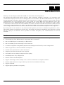
This section identifies all the major external components of the device. Both the front and rear panels are shown,
followed by a description of each panel feature. The indicator panel is described in detail in the next chapter.
The figure below shows the front panels of the device.
♦
LED Indicator Panel Refer to the next chapter, “Understanding Indicators,” for detailed information
about each of the VoIP Gateway’s LED indicators.
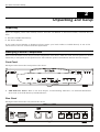
The figure below shows the rear panel of the device.
2
DG-104SH VoIP Station Gateway
♦
AC Power Connector For the included power adapter. If you use a power adapter other than the one
included with the product please make sure it has a DC output of 12VDC/1A.
♦
Diagnostic Port An RS-232 serial port used to configure the device. Plug one end of a straight-through
wired RS-232 cable to the device and the other end to a serial port of a PC running a terminal emulation
program (such as Microsoft HyperTerminal) or a VT-100 terminal.
♦
Ethernet WAN A 10/100 dual-speed Ethernet port fitted with an RJ-45 connector used to connect the
VoIP gateway to a WAN device (usually a router). This port accepts Category 3, 4 or 5 UTP cabling with an
RJ-45 connector.
♦
Ethernet LAN A 10/100 dual-speed Ethernet port fitted with an RJ-45 connector used to connect the
VoIP gateway to a LAN device (hub, switch, PC, etc.). This port accepts Category 5 or better UTP cabling
with an RJ-45 connector.
♦
Phone 1 to 4 Normal RJ-11 phone jacks used to connect telephones and fax machines. Plug your normal
telephone(s) and/or fax machine directly into any of these jacks.
%& """#
Use the following guidelines when choosing a place to install the VoIP Gateway:
♦ The surface must support at least 1 kg.
♦ The power outlet should be within 1.82 meters (6 feet) of the device.
♦ Visually inspect the power cord and see that it is secured to the AC power connector.
♦ Make sure that there is proper heat dissipation from and adequate ventilation around the device. Do not
place heavy objects on the unit.
When installing the unit on a desktop or shelf, the rubber feet included with the device should first be
attached. Attach these cushioning feet on the bottom at each corner of the device. Allow adequate space for
ventilation between the device and the objects around it.
#&'#("
Category 3, 4 or 5 UTP cable can be used to make the Ethernet connection to your WAN router.
The maximum cable run between the DG-104SH and the supporting call agent is 100 meters. The cable must be
straight (not a crossover cable) with RJ-45 connectors at each end. Make the network connection by plugging one
end of the cable into the RJ-45 jack of the DG-104SH, and the other end into a port on your WAN router.
3
DG-104SH VoIP Station Gateway
Once the device has been connected to a PC, you will need a separate IP address and a straight cable.
To connect the device to either a hub or switch, you must connect the straight cable to the Uplink port.
4
DG-104SH VoIP Station Gateway
3
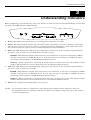
Before configuring your VoIP Gateway, take a few minutes to look over this section and familiarize yourself with
the front panel LED indicators depicted below.
♦
Power This LED is lit when the device is receiving power; otherwise, it is unlit.
♦
Status This LED will flash quickly when the CPE is either performing a self test or booting up. The LED
will remain lit when the system is ready for a connection with the Gatekeeper; it will remain dark when
the system is ready but can not receive an acknowledgement from the Gatekeeper.
♦
WAN This LED displays the connection speed, link status, and activity on the 10/100 dual-speed Ethernet
port that is used to connect to your WAN device (usually a router).
10/100M − This indicator remains unlit when there is no connection, or the port is operating at 10Mbps
through a connection to a 10BASE-T device. It is lit when the port is operating at 100Mbps through a
connection to a dual-speed or 100BASE-TX Fast Ethernet device.
Link/Act − When a good link to a powered-up but idle device is detected on a port, this indicator shines
steadily. When packets are received from the device, the indicator blinks off and on.
♦
LAN This LED displays the connection speed, link status, and activity on the 10/100 dual-speed Ethernet
port that is used to connect to your LAN.
10/100M − This indicator remains unlit when there is no connection, or the port is operating at 10Mbps
through a connection to a 10BASE-T device. It is lit when the port is operating at 100Mbps through a
connection to a dual-speed or 100BASE-TX Fast Ethernet device.
Link/Act − When a good link to a powered-up but idle device is detected on a port, this indicator shines
steadily. When packets are received from the device, the indicator blinks off and on.
♦
Phone 1 to 4 Lights when standard phone port is in use
NOTE:
If a powered-up device is connected to a port and the port’s Link/Act status indicator is unlit, the
most probable cause is a cabling or connection problem (for example, wrong cable type or bad contact)
or a device malfunction.
5
DG-104SH VoIP Station Gateway
4
In order to use the DG-104SH VoIP gateway, you must first configure it.
#&)#%*' There are two ways to configure the VoIP gateway, both of which are discussed below. They are:
♦
Using a terminal or PC running terminal emulation software connected to the diagnostic port via an RS-232
cable. In the discussion below, the terminal (or PC) is referred to as a console and the connection a console
connection.
♦
Using a web browser on a PC connected to the device via the WAN or LAN Ethernet connections. In the
discussion below, the PC running the browser is referred to as the management station.
First-time configuration must be carried out through a "console," that is, either (a) a VT100-type serial data
terminal, or (b) a computer running communications software set to emulate a VT100. The console must be
connected to the Diagnostics port. This is an RS-232 port with a 9-socket D-shell connector and DCE-type
wiring. Make the connection as follows:
1. Obtain suitable cabling for the connection.
You can use either (a) a "null-modem" RS-232 cable or (b) an ordinary RS-232 cable and a null-modem
adapter. One end of the cable (or cable/adapter combination) must have a 9-pin D-shell connector suitable
for the Diagnostics port; the other end must have a connector suitable for the console's serial
communications port.
2. Power down the devices, attach the cable (or cable/adapter combination) to the correct ports, and restore
power.
3. Set the console to use the following communication parameters for your terminal:
♦
9600 baud
♦
VT-100/ANSI compatible
♦
No parity checking (sometimes referred to as "no parity")
♦
8 data bits (sometimes called a "word length" of 8 bits)
♦
1 stop bit (sometimes referred to as a 1-bit stop interval)
♦
No Flow control
♦
VT-100/ANSI compatible
♦
Arrow keys enabled
A typical console connection is illustrated below:
6
DG-104SH VoIP Station Gateway
Once you have set an IP address for your device, you can use a Telnet program (in a VT-100 compatible
terminal mode) to access and configure it. Most of the screens are identical, whether accessed from the console
port or from a Telnet interface.
The console interface makes use of the following conventions:
Items in <angle brackets> can be toggled on or off using the space bar.
Items in [square brackets] can be changed by typing in a new value. You can use the Backspace and Delete
keys to erase characters behind and in front of the cursor.
The up and down arrow keys, the left and right arrow keys, the Tab key and the Backspace key can be used to
move between selected items. It is recommended that you use the Tab key and Backspace key for moving
around the console.
Items in UPPERCASE are commands. Moving the selection to a command and pressing Enter will execute
that command, e.g. APPLY, etc.
Please note that the command APPLY only applies for the current session. Use Save Changes from the
Main Menu for permanent changes.
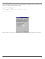
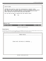
First make the console connection to the device and then power it on. If your terminal (or terminal emulation
program) is properly configured according to the specifications defined above, you will see the POST test and
the boot up process. During this process, press <Ctrl+C> to reach the Boot Menu (shown below).
7
DG-104SH VoIP Station Gateway
If the boot up process has proceeded too far and you did not reach the Boot Menu shown above, unplug the device,
plug it back in (to restart the boot up process), and press <Ctrl+C> until the Boot Menu appears.
In order for the VoIP to function, you must provide the device with the following information:
♦
Define where the device receives its IP settings from.
♦
IP settings – IP Address, Subnet Mask, and Default Gateway
♦
Gatekeeper Mode– Choose the Gatekeeper mode
♦
Gatekeeper IP –The Gatekeeper IP address is necessary if you chose the <Manual Discovery> item within the
Gatekeeper Mode
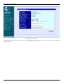
All of these settings are found in the first menu item in the Boot Menu named IP Configuration.
Use the <Tab> key to highlight the first menu item Configure IP and press <Enter>. The IP Configuration
screen will now be displayed:
8
DG-104SH VoIP Station Gateway
♦
Gatekeeper Mode Use the <Space> key to choose the Gatekeeper mode once the device is rebooted
(restarted). Choices include:
Auto Discovery – When Auto Discovery is chosen, the VoIP gateway will auto-search the Gatekeeper
from your LAN or WAN.
Manual Discovery – When Manual Discovery is chosen, the VoIP gateway will attempt to obtain the
Gatekeeper settings from the fields located just below.
No Gatekeeper – When No Gatekeeper is chosen, the VoIP gateway will not need Gatekeeper.
♦
Gatekeeper IP Enter an IP address for the Gatekeeper.
♦
BOOTP Use the <Space> key to choose the method that the VoIP gateway will use to obtain its IP
settings once it is rebooted (restarted). Choices include:
Manual – When Manual is chosen, the VoIP gateway will obtain its IP settings from the fields located
just below.
BOOTP – When BOOTP is chosen, the VoIP gateway will attempt to obtain its IP settings from a
BOOTP server located on your LAN.
DHCP – When DHCP is chosen, the VoIP gateway will attempt to obtain its IP settings from a DHCP
server located on your LAN.
♦
IP Address Enter an IP address for the VoIP gateway.
♦
Subnet Mask Enter a subnet mask for the VoIP gateway.
♦
Default Gateway Enter the IP address of the WAN device (usually a router) you are using to make the
WAN connection.
After you have finished, press <Ctrl+S> to save changes to RAM. Next, press the <Esc> key to return to the Boot
Menu. Position the cursor over the Save Changes item and press <Enter>. This will save the settings to NV-RAM
9
DG-104SH VoIP Station Gateway
so they will still be present after powering off or restarting the device. Position the cursor over the Restart System
item and press <Enter> for the changes to take effect.
Your VoIP is now configured for use.
In order to use a web browser to configure the VoIP gateway, you must make sure it has a valid Ethernet
connection to a PC or LAN via its LAN or WAN ports.
The VoIP gateway comes with a default IP address of 10.1.10.4. You must make sure the PC is in the same IP
domain as the VoIP gateway. You can do this by changing the IP address of the PC as shown below.
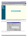
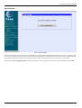
Once this is done, run any browser on the PC and point it to the default IP address of the VoIP as shown below:
10
DG-104SH VoIP Station Gateway
!
"
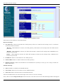
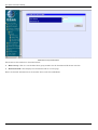
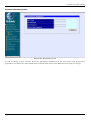
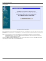
Click on the Login to the web-based management module button in the middle of the window. The following
window will be displayed:
Initially, the VoIP gateway does not have a Username or Password. To log in, simply click on the OK button.
The following window will be displayed:
11
DG-104SH VoIP Station Gateway
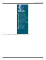
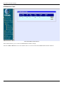
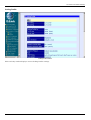
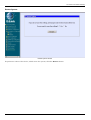
#
!!
To begin configuring the device, click on the Config IP & H.323 folder on the left-hand side of the window
(shown below).
12
DG-104SH VoIP Station Gateway
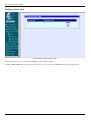
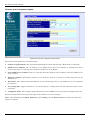
Next, click on Config Device IP Address. The following window will appear:
13
DG-104SH VoIP Station Gateway
#$!!
The items on this window are described below:
Restart Settings
♦
Get IP From Choose the method the VoIP gateway will use to obtain its IP settings once it is rebooted
(restarted). Choices include:
Manual – When Manual is chosen, the VoIP gateway will obtain its IP settings from the fields located
just below.
BOOTP – When BOOTP is chosen, the VoIP will attempt to obtain its IP settings from a BOOTP server
located on your LAN.
DHCP – When DHCP is chosen, the VoIP will attempt to obtain its IP settings from a DCHP server
located on your LAN.
♦
IP Address Enter an IP address for the VoIP gateway.
♦
Subnet Mask Enter a subnet mask for the VoIP gateway.
♦
Default Gateway Enter the IP address of the WAN device (usually a router) you are using to make the
WAN connection.
PPPoE Settings
♦
State Enables or disables the PPPoE function.
♦
User Name Enter the User Name for the PPPoE function.
♦
Password Enter the Password for the PPPoE function.
Click on the Save button at the bottom right of the screen to save the settings.
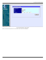
Next, click on the Config Gatekeeper item in the list at the left of the screen. The following window will appear:
14
DG-104SH VoIP Station Gateway
%&'('!!
The items on this window are described below:
Gatekeeper Information
♦
Mode Choose the Gatekeeper mode.(Default is Auto)
♦
Gatekeeper IP Address This IP address is necessary if you chose the Manual mode defined as above.
♦
Send Keepalive RRQ to Gatekeeper Enables or disables the Keepalive function.
♦
Keepalive Interval This is a user-defined Keepalive Interval
H.323 Information
♦
Display Name
♦
H.323 ID
♦
Terminal Type (0…255)
Click on the Save button at the bottom right of the screen to save the settings.
Send Register/Unregister to Gatekeeper Determines whether or not the device register to Gatekeeper.
15
DG-104SH VoIP Station Gateway
5
The DG-104SH VoIP gateway features a Boot Menu, which is described in this chapter.
To access the Boot Menu, you must first make sure the console is connected to the Diagnostics port (an RS-232
port with a 9-socket D-shell connector and DCE-type wiring) and the appropriate cabling for the connection is
being used. Please see the previous chapter, “Configuration,” for additional information. Next, power the device
on by simply plugging it in. You will see the POST test and the boot up process. During this process, press
<Ctrl+C> to reach the Boot Menu. If the boot up process has proceeded too far and you did not reach the Boot
Menu shown below, unplug the device, plug it back in (to restart the boot up process), and press <Ctrl+C> until
the Boot Menu appears.
)
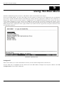
This screen allows you to enter information necessary for the initial configuration of this device.
Use the <Tab> key to highlight the first menu item on the Boot Menu, Configure IP, and press <Enter>. The IP
Configuration screen will be displayed:
16
DG-104SH VoIP Station Gateway
Each item on the IP Configuration screen is described below:
17
DG-104SH VoIP Station Gateway
♦
Gatekeeper Mode Use the <Space> key to choose the Gatekeeper mode once the device is rebooted
(restarted). Choices include:
Auto Discovery – When Auto Discovery is chosen, the VoIP gateway will auto-search the Gatekeeper
from your LAN or WAN.
.Manual Discovery – When Manual Discovery is chosen, the VoIP gateway will attempt to obtain the
Gatekeeper settings from the fields located just below.
No Gatekeeper – When No Gatekeeper is chosen, the VoIP gateway will not need Gatekeeper
♦
Gatekeeper IP Enter an IP address for the Gatekeeper.
♦
BOOTP Use the <Space> key to choose the method that the VoIP gateway will use to obtain its IP
settings once it is rebooted (restarted). Choices include:
Manual – When Manual is chosen, the VoIP gateway will obtain its IP settings from the fields located
just below.
BOOTP – When BOOTP is chosen, the VoIP gateway will attempt to obtain its IP settings from a
BOOTP server located on your LAN.
DHCP – When DHCP is chosen, the VoIP gateway will attempt to obtain its IP settings from a DHCP
server located on your LAN.
♦
IP address Enter an IP address for the VoIP gateway.
♦
Subnet mask Enter a subnet mask for the VoIP gateway.
♦
Default gateway Enter the IP address of the WAN device (usually a router) you are using to make the
WAN connection.
After you have finished, press <Ctrl+S> to save changes to RAM. Next, press the <Esc> key to return to the Boot
Menu. Position the cursor over the Save Changes item and press <Enter>. This will save the settings to NV-RAM
so they will still be present after powering off or restarting the device. Make sure the Reset button on the rear
panel of the device is in the down position. Position the cursor over the Restart System item and press <Enter> for
the changes to take effect. Your VoIP is now configured for use.
This screen allows you to set an SNMP trap manager.
18
DG-104SH VoIP Station Gateway
*
""!+
♦
SNMP AuthTrap Enables or disables the SNMP trap function.
♦
Community Enter the community name of the trap manager.
♦
IP Enter the IP address of the trap manager.
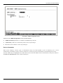
This screen displays various types of information about the DG-104SH as well as allowing you to enter
information pertaining to name, location, and how to reach the person responsible for maintaining the device.
Use the <Tab> keys to highlight the second menu item on the Boot Menu, Device Information, and press <Enter>.
The Device Information screen will be displayed:
19
DG-104SH VoIP Station Gateway
#
""!+
♦
Device Type This displays the model name of this device.
♦
MAC Address This displays the MAC address of this device.
♦
Serial Number This displays the serial number of this device.
♦
Boot PROM Version This displays the version number of the device’s startup code.
♦
Firmware Version This displays the version number of the device’s runtime code.
♦
Hardware Revision This displays the revision number of the hardware circuitry.
♦
System Country Code This is a user-defined country code for this device. < 0:USA, 1:Japan (Default),
2:Hong Kong, 3:Sweden >
♦
System Name This is a user-defined name for this device.
♦
System Location This is a user-defined physical location of the device.
♦
System Contact This is user-defined contact information for the person or department responsible for
the maintenance of this device.
!
!
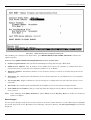
New software can be downloaded from a TFTP server.
Use the <Tab> keys to highlight the third menu item on the Boot Menu, Update Firmware and Configuration
Files, and press <Enter>. The Update Firmware and Configuration Files screen will be displayed:
20
DG-104SH VoIP Station Gateway
,!
After making your changes in the fields above, press RESET DEVICE TO START UPDATE to initiate the
update sequence.
""!+
♦
Software Update Mode This specifies downloading the image file through a WAN Link.
♦
TFTP Server Address The IP address of the TFTP server where the runtime or configuration file is
located. This entry is used only if the Firmware Update is set to Enable.
♦
Firmware Update Determines whether or not the device will try to look for a runtime image file on the
TFTP server.
♦
File Name The complete path and filename of the runtime image file on your TFTP server to be uploaded
to the device.
♦
Use Config File Toggle to Enabled to use the settings in a configuration text file when the device is reset
(rebooted).
♦
File Name The complete path and filename on the TFTP server for the desired configuration file.
♦
Last TFTP Server Address This is a read-only field that displays the IP address of the last TFTP server
to be accessed.
Note: After finishing the Update Firmware, please Must perform Factory Reset to make sure firmware
update is complete
To save all the changes made in the current session to the device’s flash memory, use the <Tab> keys to highlight
the fourth menu item on the Boot Menu, Save Changes, and press <Enter>. The Saving Settings screen will be
displayed:
21
DG-104SH VoIP Station Gateway
After the settings have been saved to NV-RAM, they will become the default settings for the device, and they will
be used every time it is powered on, reset or rebooted. The only exception to this is a factory reset, which will clear
all settings and restore them to their initial values, which were present when the device was purchased.
"
Before performing a Factory Reset, be absolutely certain that this is what you want to do. Once the reset is done,
all of the device’s settings stored in NV-RAM will be erased and restored to values present when the device was
purchased.
Note: After performing the Factory Reset, make sure to redefine the IP settings for the device in the IP
Configuration menu. Then perform a Restart System on the device. After these three procedures are
performed, your Factory Reset is complete.
To perform a Factory Reset, use the <Tab> keys to highlight the fifth menu item on the Boot Menu, Factory
Reset, and press <Enter>. The Factory Reset screen will be displayed:
22
DG-104SH VoIP Station Gateway
-.
"
To perform a system reset, use the <Tab> keys to highlight the last menu item on the Boot Menu, Restart System,
and press <Enter>. The following Reboot Device screen will be briefly displayed:
.-
23
DG-104SH VoIP Station Gateway
6
##
The DG-104SH VoIP gateway offers an embedded Web-based (hypertext) interface allowing users to manage the
device from anywhere on the network through a standard browser such as Netscape Navigator/Communicator, 4.x
or later, or Microsoft Internet Explorer, 4.x or later. The Web browser acts as a universal access tool and can
communicate directly with the device using HTTP protocol. Your browser screen may vary with the screen shots
(pictures) in this guide.
Note: This Web-based Management Module does not accept Chinese language input (or other languages
requiring two bytes per character).
*
The first step in getting started in using Web-based management for your device is to secure a browser. A Web
browser is a program that allows a person to read hypertext, for example, Netscape Navigator, 4.x or later, or
Microsoft Internet Explorer, 4.x or later. Follow the installation instructions for the browser.
The second and last step is to configure the IP interface of the device. This can be done manually through a
console. See the Configuring the VoIP Gateway using a Web Browser section of the “Configuration” chapter for
specific instructions.
$
To begin managing your device simply run the browser you have installed on your computer and point it to the IP
address you have defined for the device. The URL in the address bar should read something like:
http://123.123.123.123, where the numbers 123 represent the IP address of the device.
In the page that opens, click on the following Login to the web-based management module button:
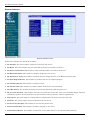
This categories listed on the left-side of the web-based management module include: Config IP & H.323 (Config
Device IP Address and Config H.323), Device Information, Telephony Configuration (System Gains and
Prefer Codec Table), Dial Address Configuration (Basic and Advance), DHCP Configuration (Dynamic
IP Assignment and Static IP Assignment), NAT Configuration (NAT Configuration and Local Server
Configuration), SNMP Trap Configuration, Administration Management, Monitor (Ethernet
Statistics, DSP Statistics, Tcid Configuration, and Coding Profile), Firmware and Configuration
Update, Save Changes, Factory Reset, and Restart System.
24
DG-104SH VoIP Station Gateway
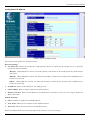
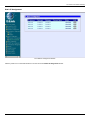
#!!
#$!!
The items on this window are described below:
Restart Settings
♦
Get IP From Choose the method the VoIP gateway will use to obtain its IP settings once it is rebooted
(restarted). Choices include:
Manual – When Manual is chosen, the VoIP gateway will obtain its IP settings from the fields located
just below.
BOOTP – When BOOTP is chosen, the VoIP will attempt to obtain its IP settings from a BOOTP server
located on your LAN.
DHCP – When DHCP is chosen, the VoIP will attempt to obtain its IP settings from a DCHP server
located on your LAN.
♦
IP Address Enter an IP address for the VoIP gateway.
♦
Subnet Mask Enter a subnet mask for the VoIP gateway.
♦
Default Gateway Enter the IP address of the WAN device (usually a router) you are using to make the
WAN connection.
PPPoE Settings
♦
State Enables or disables the PPPoE function.
♦
User Name Enter the User Name for the PPPoE function.
♦
Password Enter the Password for the PPPoE function.
Click on the Save button at the bottom right of the window to save the settings.
25
DG-104SH VoIP Station Gateway
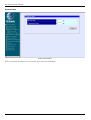
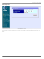
$%&'&
%&'('!!
The items on this window are described below:
Gatekeeper Information
♦
Mode Choose the Gatekeeper mode.(Default is Auto)
♦
Gatekeeper IP Address This IP address is necessary if you chose the Manual mode defined as above.
♦
Send Keepalive RRQ to Gatekeeper Enables or disables the Keepalive function.
♦
Keepalive Interval This is a user-defined Keepalive Interval
H.323 Information
♦
Display Name
♦
H.323 ID
♦
Terminal Type (0…255)
Click on the Save button at the bottom right of the screen to save the settings.
Send Register/Unregister to Gatekeeper Determines whether or not the device register to Gatekeeper.
26
DG-104SH VoIP Station Gateway
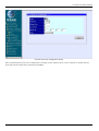
#
!!
The items on this window are described below:
♦
Device Type This displays the model name of this device.
♦
MAC Address This displays the MAC address of this device.
♦
Boot PROM Version This displays the version number of the device’s startup code.
♦
Firmware Version This displays the version number of the device’s runtime code.
♦
Hardware Revision This displays the revision number of the hardware circuitry.
♦
DSP Version This displays the Digital Signal Processor version, if any.
♦
Country Code This is a user-defined country code for this device. < 0:USA, 1:Japan (Default), 2:Hong
Kong, 3:Sweden >
♦
Serial Number This field is for a user-determined identification number.
♦
System Name This is a user-defined name for this device.
♦
System Location This is a user-defined physical location of the device.
♦
System Contact This is user-defined contact information for the person or department responsible for
the maintenance of this device.
Click on the Save button at the bottom right of the window to save the settings.
27
DG-104SH VoIP Station Gateway
-/!!
Enter the desired information on the window above and then click Save.
28
DG-104SH VoIP Station Gateway
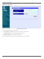
!
(
"!!
This window allows you to view the Prefer Codec Table settings.
Click the number of Tcid column on the window above to access the second Prefer Codec Table window:
29
DG-104SH VoIP Station Gateway
"!!
The items on this window are described below:
♦
Tcid This displays the port number of this device. (0: port1, 1: port2, 2: port3, 3: port4)
♦
Prefer Codec Type This is a user-defined prefer codec type for the port shown as above.
Click on the Save button at the bottom right of the window to save the settings.
30
DG-104SH VoIP Station Gateway
#
)
! "
*+
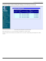
First Analog Port Telephone No. Table window
This window allows you to view the Analog Port Telephone No. Table settings.
Click the number of Tcid column on the window above to access the second Analog Port Telephone No. Table
window.
31
DG-104SH VoIP Station Gateway
$*&"!!
The items on this window are described below:
♦
Tcid This displays the port number of this device. (0: port1, 1: port2, 2: port3, 3: port4)
♦
Telephone No. This is a user-defined Caller ID number for the port shown as above.
♦
Caller ID Name This is a user-defined Caller ID name.
♦
Private Type Determines whether or not the user would like to block/unblock the Caller ID number and
Caller ID name.
♦
Call Forward Toggle to Enabled to use the Call Forward function.
♦
Call Forward to Telephone No. This is a user-defined telephone number for call forward.
♦
Process Type This is a user-defined which situation will activate Call Forward function. The entry is
used only if the Call Forward is set to Enable.
Click on the Save button at the bottom right of the window to save the settings.
32
DG-104SH VoIP Station Gateway
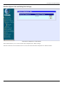
),
! "+
#*&"!!
This window allows you to view the Data Port Telephone No. Table settings
Click the Add icon on the window above to access the First Data Port Telephone No. Table window:
33
DG-104SH VoIP Station Gateway
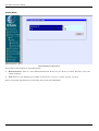
#*&"!!
The items on this window are described below:
♦
Prefix Strip Telephone No. This is a user-defined prefix strip number for outgoing call to another
device..
♦
Destination IP Address Enter the IP address of the destination you would like to call. One prefix
telephone number will map to one destination IP address.
Enter the desired information on the window above and then click Save.
34
DG-104SH VoIP Station Gateway
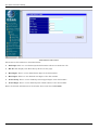
#)#!!
!
!+-.
!
$!!
The items on this window are described below:
♦
Analog This Mode allow user to setup advanced ingress calls and dialing rule settings for the gateway’s
voice ports.
♦
Data This Mode allow user to setup advanced egress calls and dialing rule settings via the gateway’s data
ports
Choose the Analog or Data Mode then click Next.
35
DG-104SH VoIP Station Gateway
#
!
$#"!!
The items on this window are described below:
♦
Destination ID. This is a user-defined destination ID for the port shown as below. The ID is only and
cannot duplicate.
♦
Tcid This is a user-defined port number of this device. (0: port1, 1: port2, 2: port3, 3: port4)
Enter the desired information on the window above and then click Next.
36
DG-104SH VoIP Station Gateway
$%/"!!
The items on this window are described below:
♦
Hunt Group. This is a user-defined hunt group number for the destination ID shown as below.
♦
Destination ID. This displays the destination ID we set last page.
Enter the desired information on the window above and then click Next.
37
DG-104SH VoIP Station Gateway
$$"!!
The items on this window are described below:
♦
Dial Digit This is a user-defined prefix dial number when user make the call.
♦
HG ID This displays the Hunt Group ID we set last page.
♦
Min Digits This is a user-defined min digits of the dial number
♦
Max Digits This is a user-defined max digits of the dial number
♦
Prefix Strip This is a user-defined prefix stripped digits of the dial number
♦
Prefix Digit This is a user-defined prefix added number of the dial number
Enter the desired information on the window above and then click Finish.
38
DG-104SH VoIP Station Gateway
!
$#"!!
The items on this window are described below:
♦
Destination ID. This is a user-defined destination ID for the port shown as below. The ID is only and
cannot duplicate.
♦
IP Address Enter the destination IP address of outgoing calls.
Enter the desired information on the window above and then click Next.
39
DG-104SH VoIP Station Gateway
$%/"!!
The items on this window are described below:
♦
Hunt Group. This is a user-defined hunt group number for the destination ID shown as below.
♦
Destination ID. This displays the destination ID we set last page.
Enter the desired information on the window above and then click Next.
40
DG-104SH VoIP Station Gateway
$$"!!
The items on this window are described below:
♦
Dial Digit This is a user-defined prefix dial number when user make the call.
♦
HG ID This displays the Hunt Group ID we set last page.
♦
Min Digits This is a user-defined min digits of the dial number
♦
Max Digits This is a user-defined max digits of the dial number
♦
Prefix Strip This is a user-defined prefix stripped digits of the dial number
♦
Prefix Digit This is a user-defined prefix added number of the dial number
Enter the desired information on the window above and then click Finish.
41
DG-104SH VoIP Station Gateway
##!!
(
$$"!!
This window allows you to view the ATPM Address Table settings
Click the Add or Delete icon on the window above to access the Second ATPM Address Table window:
42
DG-104SH VoIP Station Gateway
$$"!!
Enter the desired information on the window above and then click Save.
43
DG-104SH VoIP Station Gateway
#$
(
$%/"!!
This window allows you to view the ATPM Hunt Group Table settings
Click the Add or Delete icon on the window above to access the Second ATPM Hunt Group Table window:
44
DG-104SH VoIP Station Gateway
$%/"!!
Enter the desired information on the window above and then click Save.
45
DG-104SH VoIP Station Gateway
# (
$#"!!
This window allows you to view the ATPM Destination Table settings
Click the Add or Delete icon on the window above to access the Second ATPM Destination Table window:
46
DG-104SH VoIP Station Gateway
$#"!!
Enter the desired information on the window above and then click Save.
47
DG-104SH VoIP Station Gateway
#
#-$!!
Enter the desired information on the window above and then click Save.
48
DG-104SH VoIP Station Gateway
#
$!!
0!!"
!!+
49
DG-104SH VoIP Station Gateway
$!!
Enter the desired information on the window above and then click Save.
50
DG-104SH VoIP Station Gateway
#
*$
!!
After entering the desired information on the window above, enable or disable the NAT Function and then click
Save.
51
DG-104SH VoIP Station Gateway
/
1
!!
!!!-!
&
0!!"
!!+
52
DG-104SH VoIP Station Gateway
1
!!
After completing the local server configuration settings on the window above, select enabled or disabled in the
drop-down menu under State and then click Save.
53
DG-104SH VoIP Station Gateway
*
!!
The items on this window are described below:
♦
Trap Manager IP Address The IP address of the trap receiving station.
♦
Community Name A user-defined SNMP community name.
♦
SNMP AuthTrap Enable or disable the SNMP trap.
Click on the Save button at the bottom right of the window to save the settings.
54
DG-104SH VoIP Station Gateway
#!
$!!
To add or change a User Account, fill in the appropriate information in the User Name, Old Password (if
applicable), New Password, and Confirm New Password fields. Click on the Save button to keep the settings.
55
DG-104SH VoIP Station Gateway
,
!!
Items in the window are described as follows:
♦ Rx Packets The total number of packets received by the device.
♦ Rx Bytes The total number of bytes contained in packets received by the device.
♦ Rx Non Ucast Packets The number of non-unicast packets received by the device.
♦ Rx Discard Packets The number of packets dropped by the device.
♦ Rx Frame Too Long The number of packets that are larger than the 1514 Ethernet packet limit.
♦ Rx Non-Aligned Errors The number of packets that are not aligned properly.
♦ Rx Collision Errors The number of collision errors.
♦ Rx Short Frames The number of packets smaller than the 64-octet minimum.
♦ Rx CRC Errors The number of packets received that failed the CRC checksum test.
♦ Rx Overrun Packets The number of packets received that exceed the 1518 octet maximum length imposed
on Ethernet packets. Overrun packets are generated by some proprietary software applications.
♦ Tx Packets The total number of valid packets transmitted by the device since the last reset.
♦ Tx Bytes The total number of bytes transmitted by the device.
♦ Tx Non Ucast Packets The number of non-unicast packets sent.
♦ Tx Discard Packets The number of packets dropped by the device.
♦ Tx Heartbeat Errors The number of heartbeat errors. This relates to an internal timing function.
56
DG-104SH VoIP Station Gateway
♦ Tx Late Collision The number of late collisions.
♦ Tx Retransmission Limit The number of times the device had to retransmit packets.
♦ Tx Underrun Packets This counter shows the number of runt packets transmitted by the device that are
less than the allowed 64-octet minimum length. Underrun packets occur due to jam signals generated by
collisions, backpressure, etc.
♦ Tx Carrier Sense Lost The number of times packets were lost due to carrier sense lost.
#!!
This window displays a variety of DSP statistics.
57
DG-104SH VoIP Station Gateway
!
!!
This read-only window displays a variety of Tcid configuration settings.
58
DG-104SH VoIP Station Gateway
!
!!
This read-only window displays various Coding Profile settings.
59
DG-104SH VoIP Station Gateway
!
!
,!
!!
The items on this window are described below:
♦
Software Update Mode This specifies downloading the image file through a WAN Link or LAN Link.
♦
TFTP Server Address The IP address of the TFTP server where the runtime or configuration file is
located. This entry is used only if the Firmware Update is set to Enable.
♦
Last TFTP Server Address This is a read-only field that displays the IP address of the last TFTP server
to be accessed.
♦
Firmware Update Determines whether or not the device will try to look for a runtime image file on the
TFTP server.
♦
File Name The complete path and filename of the runtime image file on your TFTP server to be uploaded
to the device.
♦
Use Config File Toggle to Enabled to use the settings in a configuration text file when the device is reset
(rebooted).
♦
Config File Name The complete path and filename on the TFTP server for the desired configuration file.
Click on the Save button at the bottom right of the window to save the settings.
Note: After finishing the Update Firmware, please Must perform Factory Reset to make sure firmware
update is complete
60
DG-104SH VoIP Station Gateway
!!
After the settings have been saved to NV-RAM, they will become the default settings for the device, and they will
be used every time it is powered on, reset or rebooted. The only exception to this is a factory reset, which will clear
all settings and restore them to their initial values, which were present when the device was purchased.
Click on the Save Configuration button at the bottom of the window to save the system settings to NV-RAM.
61
DG-104SH VoIP Station Gateway
"
-.#
2!!
Before performing a Factory Reset, be absolutely certain that this is what you want to do. Once the reset is done,
all of the device’s settings stored in NV-RAM will be erased and restored to values present when the device was
purchased.
Note: After performing the Factory Reset, make sure to redefine the IP settings for the device in the IP
Configuration menu. Then perform a Restart System on the device. After these three procedures are
performed, your Factory Reset is complete.
Click on the Reset to Factory Default button at the bottom of the window to reset the NV-RAM to the default
values that were present when you purchased the device.
62
DG-104SH VoIP Station Gateway
"
.-!!
To perform a reboot of the device, which resets the system, click the Restart button.
63
DG-104SH VoIP Station Gateway
7
The DG-104SH VoIP gateway offers a line-at-a-time prompt and response scheme to execute various
configuration instructions. The interface displays a single prompt character ggdbg> when it is ready to accept a
command (ex. ggdbg>set or ggdbg>show).
Typing a question mark after the ggdbg> prompt will display a list of helpful user commands. Please note that all
characters must be entered in lower case. For the sake of explanation, all command line examples in this chapter
are in bold type.
See below for a list of some of the most commonly used commands, parameter(s), and examples of their usage.
!
nwdbg system reboot
Definition:
This command is used to restart the device.
Parameter(s):
None.
Example:
nwdbg system reboot
nwdbg save changes
Definition:
This command is used to save configuration changes into flash and then restart the device.
Parameter(s):
None.
Example:
nwdbg save changes
nwdbg factory reset
Definition:
This command is used to change all of the configuration data to the default values, save the
new configuration data into flash, and then restart the device.
Parameter(s):
None.
Example:
nwdbg factory reset
nwdbg un <USERNAME>
Definition:
This command sets the username if there is a username string, or shows the
username/password if only nwdbg un is typed.
Parameter(s):
<USERNAME, maximum string length is 12 characters>
Example:
nwdbg un 123456789012
nwdbg pw <PASSWORD>
Definition:
This command sets the password if there is a password string, or shows the
username/password if only nwdbg pw is typed.
Parameter(s):
<PASSWORD, maximum string length is 12 characters>
Example:
nwdbg pw
nwdbg slic <0|1>
Definition:
Parameter(s):
Example:
This command changes the Subscriber Line Interface Circuit (SLIC) state to standby or
active, or shows the SLIC state if only nwdbg slic is typed.
<slic state, 0 : standby, 1 : active >
nwdbg slic 0
64
DG-104SH VoIP Station Gateway
nwdbg dtmf_relay <0|1>
Definition:
This command turns the Dual Tone Multiple Frequency (DTMF) relay function on or off, or
shows the DTMF relay state if only nwdbg dtmf_relay is typed.
Parameter(s):
<0 : off, 1 : on>
Example:
nwdbg dtmf_relay 0
nwdbg mac <MAC ADDRESS>
Definition:
This command sets the MAC address of the voice link, or shows the MAC address if only
nwdbg mac is typed.
Parameter(s):
<MAC ADDRESS, the format is XX:XX:XX:XX:XX:XX>
Example:
nwdbg mac 00:50:ba:08:24:56
nwdbg ip <dhcp|bootp|manual>
Definition:
This command sets the software boot mode to DHCP or BOOTP or Manual mode.
If only nwdbg ip is typed, this command shows the IP configuration.
DHCP: While the system is booting, the system acts as a DHCP client.
BOOTP: While the system is booting, the system acts as a BOOTP client. This mode is used
to set the device's IP address and upgrade the software.
Manual: While the system is booting, the system uses a fixed IP address. The fixed IP
address can be set by nwdbg ip <IP ADDRESS>.
Parameter(s):
<dhcp|bootp|manual>
Example:
nwdbg ip dhcp
nwdbg ip <IP ADDRESS>
Definition:
This command sets the fixed IP address, which is used as the system's IP address if the
software boot mode is Manual mode.
If only nwdbg ip is typed, this command shows the IP configuration.
Parameter(s):
<IP ADDRESS>
Example:
nwdbg ip 10.1.1.120
nwdbg mask <SUBNET MASK>
Definition:
This command sets the fixed subnet mask, which is used as the system's subnet mask if the
software boot mode is Manual mode.
If only nwdbg mask is typed, this command shows the IP configuration.
Parameter(s):
<SUBNET MASK>
Example:
nwdbg mask 255.0.0.0
nwdbg gw <GATEWAY IP>
Definition:
This command sets the fixed GW address, which is used as the system's GW address if the
software boot mode is Manual mode.
If only nwdbg mask is typed, this command shows the IP configuration.
Parameter(s):
<GATEWAY IP>
Example:
nwdbg gw 10.1.1.254
nwdbg tftp <0|1>
Definition:
Parameter(s):
Example:
This command sets the software download link to either a WAN link or a LAN link.
If only nwdbg tftp is typed, this command shows the download link.
<0:WAN link, 1:LAN link>
nwdbg tftp 0
nwdbg dns <DNS IP>
Definition:
This command sets the Domain Name Server's IP address.
65
DG-104SH VoIP Station Gateway
Parameter(s):
Example:
If only nwdbg dns is typed, this command shows the DNS IP/STATE.
<DNS IP>
nwdbg dns 10.1.1.5
nwdbg dns <disable|enable>
Definition:
This command turns on/off the DNS function.
If only nwdbg dns is typed, this command shows the DNS IP/STATE
Parameter(s):
[disable | enable]
Example:
nwdbg dns disable
nwdbg country <code>
Definition:
This command provides country code setting interface to config the tone frequency for
different country.
If only nwdbg country is typed, this command shows the COUNTRY CODE
Parameter(s):
<0:USA, 1:Japan (Default)>
Example:
nwdbg country 1
nwdbg config
Definition:
Parameter(s):
Example:
This command shows all the configuration settings made by nwdbg commands.
None.
nwdbg config
ping <DEST IP> <OPTIONS>
Definition:
This command lets the user ping an IP address from the device.
Parameter(s):
<DEST IP: The host ip address>
<OPTIONS, -t : Ping the specifed host until stopped (type SPACE).
-n count: Number of echo requests to send.
-w timeout: Timeout in seconds to wait for each reply.
-i interval: The interval in half-seconds between two echo requests.>
Example:
ping 10.1.1.6 -n 100 -w 2 -i 1
!
When the user enters tftp, the screen will show all commands about the TFTP client:
ggdbg>tftp
tftp srvip <IP ADDRESS>
tftp get <FILENAME>
– set the IP address of TFTP server
– get the remote image file
if <FILENMAE> is not specified, the
image file name in EEPROM will be
employed.
– update the image in flash
tftp update
Current Settings :
TFTP Server IP Address : 172.16.6.245
Image File Name : 102nmm01.tfp
tftp srvip <IP ADDRESS>
Definition:
This command sets the IP address of the TFTP server. The image must be resident on that
TFTP server. If the IP address is invalid, the message ERROR will be displayed.
Example:
ggdbg>tftp srvip 172.16.6.245
OK
tftp get <FILENAME>
66
DG-104SH VoIP Station Gateway
Definition:
Example:
tftp update
Definition:
Example:
Gets the image from the TFTP server. The <FILENAME> is the name of the image on the
TFTP server. If any error happened during downloading image, the message ERROR will
be displayed. When the user enters tftp get, the file name in EEPROM will be employed.
ggdbg>tftp get c:\102nmm.tfp
Download d:\project\dg102\102nmm.tfp ...\
OK
This command updates the image in FLASH. The image is downloaded for storage in
DRAM. If any error happens during the update of the image, the message ERROR will be
displayed.
ggdbg>tftp update
.. Erase Runtime Flash Memory ... Done
.. Program Runtime Flash Memory ... Done
OK
67
DG-104SH VoIP Station Gateway
A
!"#$
%&#!'(!
)')*&+',#!
-#./#!0*'01
2
3324'445
- $-.$&%666
3324'445
- $-.$&%6 6---1445
--.#+!#
6---14445
- $-.#+!
)!#$7!#!$!!!87.""!#
))))&!'%+!
,9:#$1
/:'6:;%:
9:6/&::3&::
%/:%+!#$/"!(!:#$7#!
3
3<
$$$!
:::7-./!
!
3&:+(+(=$&6566
7!$!!(
&("#!$.(.!!!7==$(.!#$!"#
#+(+#$
:.=!>!!7!!$":#7!$"!+(
:$$
.!#!:#'/.($.<
.!#!:#:
:'/
:
68
DG-104SH VoIP Station Gateway
+!!$!7$$.(./$2=3&:
"#
$
:
$
2
34'44&!<'
#
34'44&!<'
#
%&
<'9!(!(
#
42,0%,??*++
'
@4'445
- $-.2
3
@4'445
- $-.
3
$ 9A$
@9/%5/$
/%/7!
%/6)%/'
()
4*4B/
)
4**B/
*+
*C*C#$!(
/
6!/
*4;*4-304*46-/*4
,!-.
///$$5
/-/$$5
)//6/$$5
5&6/$$5
/!#<
69
Offices
AUSTRALIA
D-LINK AUSTRALASIA
Unit 16, 390 Eastern Valley Way Roseville, NSW 2069 Australia
TEL: 61-2-9417-7100 FAX: 61-2-9417-1077 TOLL FREE (Australia): 1800 177 100 TOLL FREE (New Zealand): 0800-900900
URL: www.dlink.com.au E-MAIL: [email protected] & [email protected]
CANADA
D-LINK CANADA
2180 Winston Park Drive, Oakville, Ontario, L6H 5W1 Canada
TEL: 1-905-829-5033 FAX: 1-905-829-5223 BBS: 1-965-279-8732 TOLL FREE: 1-800-354-6522
URL: www.dlink.ca FTP: ftp.dlinknet.com E-MAIL: [email protected]
DENMARK
D-LINK DENMARK
Naverland 2 DK-2600 Glostrup Copenhagen, Denmark
TEL:45-43-969040 FAX:45-43-424347 URL: www.dlink.dk E-MAIL: [email protected]
EGYPT
D-LINK MIDDLE EAST
7 Assem Ben Sabet Street, Heliopolis Cairo, Egypt
TEL: 202-245-6176 FAX: 202-245-6192 URL: www.dlink-me.com E-MAIL: [email protected] & [email protected]
FRANCE
D-LINK FRANCE
Le Florilege #2, Allee de la Fresnerie, 78330 Fontenay le Fleury, France
TEL: 33-1-3023-8688 FAX: 33-1-3023-8689 URL: www.dlink-france.com E-MAIL: [email protected]
GERMANY
D-LINK GERMANY
Bachstrae 22, D-65830 Kriftel, Germany
TEL: 49-(0)6192-97110 FAX: 49-(0)6192-9711-11 URL: www.dlink.de BBS: 49-(0)6192-971199 (analog)
BBS: 49-(0)6192-971198 (ISDN) INFO: 00800-7250-0000 (toll free) HELP: 00800-7250-4000 (toll free)
REPAIR: 00800-7250-8000 E-MAIL: [email protected] & [email protected]
INDIA
D-LINK INDIA
Plot No.5, Kurla-Bandra Complex Rd., Off Cst Rd., Santacruz (E) Bombay - 400 098 India
TEL: 91-22-652-6696 FAX: 91-22-652-8914 URL: www.dlink-india.com E-MAIL: [email protected]
ITALY
D-LINK ITALY
Via Nino Bonnet n.6/b, 20154 Milano, Italy
TEL: 39-02-2900-0676 FAX: 39-02-2900-1723 URL: www.dlink.it E-MAIL: [email protected]
JAPAN
D-LINK TOKYO
10F, 8-8-15 Nishi-Gotanda, Shinagawa-ku, Tokyo 141 Japan
TEL: 81-3-5434-9678 FAX: 81-3-5434-9868 URL: www.d-link.co.jp E-MAIL: [email protected]
SINGAPORE
D-LINK INTERNATIONAL/D-LINK SINGAPORE
1 International Business Park, #03-12 The Synergy, Singapore 609917
TEL : 65-774-6233 FAX: 65-774-6322 E-MAIL: [email protected] URL: www.dlink-intl.com
SWEDEN
D-LINK SWEDEN
P. O. Box 15036, S-167 15 Bromma, Sweden
TEL: 46-(0)8564-61900 FAX: 46-(0)8564-61901 E-MAIL: [email protected] URL: www.dlink.dk
TAIWAN
D-LINK TAIWAN
2F, No. 119 Pao-Chung Rd, Hsin-Tien, Taipei, Taiwan
TEL: 886-2-2910-2626 FAX: 886-2-2910-1515 URL: www.dlinktw.com.tw E-MAIL: [email protected]
U.K.
D-LINK EUROPE/D-LINK U.K.
4th Floor, Merit House, Edgeware Road, Colindale, London NW9 5AB U.K.
TEL: 44 (0) 20-8731-5555 FAX: 44 (0) 20-8731-5511 URL: www.dlink.co.uk E-MAIL: [email protected]
U.S.A.
D-LINK U.S.A.
53 Discovery Drive, Irvine, CA 92618, USA
TEL: 1-949-788-0805 FAX: 1-949-753-7033 BBS: 1-949-455-1779 & 1-949-455-9616 INFO: 1-800-326-1688
URL: www.dlink.com E-MAIL: [email protected] & [email protected]
#
!" #
Product
Model
Product Serial
No.
* Product installed in type of
computer (e.g., Compaq 486)
* Product installed Computer serial
No.
$
$
!!!
!!!
!!!!!!!
!
"
! !"!
!"!#$%!%&'''''''''''''''''''''''''''''
#
! !
"
!#()(*%!%+!%+(%! ,-!-
!. !//0!1!#$%%&2)
!+32
!+32
* !+324!%&''''''''''''''
$
!!
!
"
!#12!12!+32!12!,-! %56!5 !%127!%&''''''''''''''''''''
%
&
!
"
!.8%!
&)-$%&%!
&-$%&%
!* $
,
! !* $
!* $
!19*(*
!%&'''''''''''''''''
'
!#)%8&6! 3&%!+36!*#!*5
!#%86%!*%6!%&'''''''''''''''''''''
(
!
!*!$66!$3%!.!%!(6!"!:$%%!5%6
!:%!&%!+&!9%!
%%!,%%!%!1*:
! %&!!%&'''''''''''''
)*+,
!;!<2&=>''''''''''''''''''''''!"3 )2%
-.////////////////////////////////////////////////////////////