1
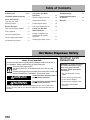
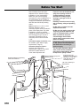
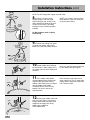
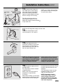
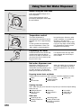
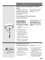
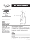
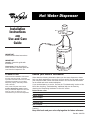
Hot Water Dispenser
®
Installation
Instructions
AND
Use and Care
Guide
IMPORTANT:
Read and save these instructions.
IMPORTANT:
Installer: Leave this guide with
homeowner.
Homeowner: Keep this guide for
future reference. Save this guide for
local electrical inspector’s use.
A Note to You
Record your model’s information
Please read the Installation Instructions
and Use and Care Guide. It contains
important information about how to install,
operate and maintain your hot water
dispenser properly and safely. Please
read it carefully.
Write down the following information about your hot water dispenser to better
help you obtain assistance or service if you ever need it. You will need to know
your complete model number and serial number. You can find this information
on the model and serial number label/plate.
Also, please complete and mail the
Product Registration Card provided
with your hot water dispenser. This card
helps us notify you about any new
information for your hot water dispenser.
Builder/dealer name
If you need assistance or service, first see the “Troubleshooting” section of this
book. After checking “Troubleshooting,” additional help can be found by
checking the “Requesting Assistance or Service” section.
Address
Phone number
Model number
Serial number
Purchase date
Date installed
(See the “Parts and Features” section for model and serial number label/plate
location.)
Keep this book and your sales slip together for future reference.
Part No. 3192760
Table of Contents
A Note to you . . . . . . . . . . . . Cover
Hot Water Dispenser Safety . . . . 2
Parts and Features . . . . . . . . . . . 3
How your hot water
dispenser works . . . . . . . . . . . . . . 3
Using Your Hot Water
Dispenser . . . . . . . . . . . . . . . . . 10
Before using the first time . . . . . . 10
Requesting Assistance
or Service . . . . . . . . . . . . . . . . . 13
Temperature control . . . . . . . . . . 10
Warranty . . . . . . . . . . . . . . . . . . 14
Dispensing hot water . . . . . . . . . 10
Before You Start . . . . . . . . . . . . . 4
Hot water dispenser uses . . . . . . 10
Tools and materials needed. . . . . . 5
Caring For Your Hot
Water Dispenser . . . . . . . . . . . . 11
Parts supplied. . . . . . . . . . . . . . . . 5
Water supply requirements . . . . . . 5
Energy-saving tips and . . . . . . . . .
preparation for periods
of nonuse . . . . . . . . . . . . . . . . . . 11
Installation Instructions . . . . . . . . . 6
Cleaning the spout screen. . . . . . 11
Electrical requirements . . . . . . . . . 5
Troubleshooting. . . . . . . . . . . . . 12
Hot Water Dispenser Safety
Your safety and the safety of
others is very important.
We have provided many important safety messages in this manual and on
your appliance. Always read and obey all safety messages.
This is the safety alert symbol.
This symbol alerts you to hazards that can kill or hurt you and
others.
All safety messages will be preceded by the safety alert symbol and
the word “DANGER” or “WARNING”. These words mean:
DANGER
You will be killed or seriously injured if
you don’t follow instructions.
WARNING
You can be killed or seriously injured if
you don’t follow instructions.
IMPORTANT SAFETY
INSTRUCTIONS
WARNING: To reduce the risk of
fire, electrical shock, or injury
when using your hot water
dispenser, follow these basic
precautions:
• Plug into grounded 3 prong
outlet.
• Do not remove ground prong.
• Do not use an adapter.
All safety messages will identify the hazards, tell you how to reduce the
chance of injury, and tell you what can happen if the instructions are not
followed.
2
• Do not use an extension cord.
• Disconnect power before
servicing.
Parts and Features
How your hot water dispenser works
Water is electrically heated to a
brewing/cooking hot 190°F by a
tank that mounts under the sink. A
thermostat maintains it at this
approximate temperature. When you
turn the On/Off Cap, cold water
enters the bottom of the tank and
forces hot water out of the faucet.
The system is vented so the tank is
not pressurized.
Use this hot water dispenser
illustration to help you quickly learn
how to install and use your new hot
water dispenser. Page numbers are
listed to help you find more detailed
information about that feature.
On/Off cap
(Pages 6, 7, 9, 10)
Spout
(Pages 6, 7, 11)
Quick-connect fitting
(Page 9)
Cold water
supply line
from saddle
valve
(Page 9)
Clear
tubing
(Page 8)
Hot water supply
line to spout
(Page 8)
Quick-connect fitting
(Page 8)
Mounting bracket
located behind tank
(Page 7)
Temperature
Control
(Pages 9, 10)
Tank
(Page 7)
Model and
serial number
label/plate
Drain plug
(Page 11)
3
Before You Start
Check location where hot water
dispenser will be installed. Proper
installation is your responsibility.
Make sure you have everything
necessary for correct installation. It is
the responsibility of the installer to
comply with installation specifications
and with state and local plumbing
codes.
If spout is not to be installed in sink
spray hose opening, contact a
qualified installer for the best
procedure for cutting a spout
opening in your type of sink or
countertop.
Spout requires a 1-1/16" to 1-3/8"
diameter opening in sink or
countertop. Spout can be installed in
place of sink spray hose. For other
installations, contact a qualified
installer for best procedure to drill a
hole through your type of sink or
countertop. Thickness of sink or
countertop hole must not exceed
1-1/8".
Do Not store or operate hot water
dispenser below 32°F.
Cold water supply connection must
be available. (See “Water supply
requirements,” Page 5.)
Temperature Control must be turned
to “Off” position and the dispenser
tank filled before connecting to
electrical supply.
Grounded electrical outlet is
required. (See “Electrical
requirements,” Page 5.) The outlet
should be located within 42"
of hot water dispenser tank.
Plumbing connections must comply
with all sanitary, safety and plumbing
codes.
Do Not use pipe sealing compounds.
They may get inside dispenser and
cause an unpleasant taste or smell.
Water connections use quickconnect fittings which Do Not
require sealing compounds to keep
them from leaking.
This hot water dispenser is Not a
water purifier. Some installations
may require a water filtering system
to improve the quality of water.
Spout installed in spray hose
opening in sink.
Important: Observe all governing
codes and ordinances.
If spout is not to be
installed in sink spray hose
opening, cut 1-1/16" min. —
1-3/8" max. dia. sink or
countertop cutout.
1-1/8" max. countertop or
sink thickness
Cold
water
line
Tank
must be
mounted
vertically.
11-1/8"
42" max. — electrical
outlet to hot water
dispenser tank.
5-5/8"
Saddle
valve
4
6-3/4"
Before You Start cont.
Tools and materials needed
ruler or
measuring tape
pliers
Electrical requirements
WARNING
pencil
3-prong
ground-type
wall receptacle
3-prong
ground
plug
gloves
flat-blade
screwdriver
safety
glasses
tubing cutter
1/4" drill bit
hand or
electric drill
open-end wrench(es)
to fit saddle valve
1/4" O.D. copper
tubing
bucket or pan
2 mounting bracket screws (and
2 plastic anchors if attaching to
dry wall)
Saddle valve kit to fit
water supply line
Kit must meet all local
codes and ordinances.
Electrical Shock Hazard
Plug into a grounded 3 prong
outlet.
Do not remove ground prong.
Do not use an adapter.
Do not use an extension cord.
Failure to follow these
instructions can result in death,
fire, or electrical shock.
If codes permit and a separate
ground wire is used, it is
recommended that a qualified
electrician determine that the
ground path is adequate.
A 120-volt, 60-Hz, AC-only 15- or
20- ampere fused, grounded
electrical supply is required. It is
recommended that a separate circuit
serving only your hot water dispenser
be provided. Use an outlet that
cannot be turned on/off by a switch.
ground
prong
power
supply cord
Recommended ground method
For your personal safety, the hot
water dispenser must be grounded.
This appliance is equipped with a
power supply cord having a 3-prong
ground plug. To minimize possible
shock hazard, the cord must be
plugged into mating, 3-prong, groundtype wall receptacle, grounded in
accordance with all national and local
codes and ordinances. If a mating
wall receptacle is not available, it is
the personal responsibility and
obligation of the customer to have a
properly grounded, 3-prong, wall
receptacle installed by a qualified
electrician.
Parts supplied
Remove parts from packages.
Check that all parts were
included.
Water supply requirements
gasket
spout
assembly
clamp
tank
mounting
bracket
tank
If local codes permit, the hot water
dispenser feed line should be
connected to the cold water supply
line using a saddle tapping valve.
If this unit is replacing a hot water
dispenser connected to a hot water
supply, the existing connection may
be used.
Important: If local codes Do Not
permit the use of saddle valves,
special feed valves can be
obtained from your local plumbing
supply distributor.
A water filter is recommended if
your water supply contains sand,
grit or other particles. If a filter is
used, the water pressure to the
dispenser should not drop below
20 psi.
Connection to hot water line is not
recommended. Energy will be wasted
in heating the water twice and the
magnesium rod used in household
heating may produce a “rotten egg”
taste.
5
Installation Instructions
3. 6.
15.
2.
Numbers
correspond
to steps.
5.
4.
5.
clear
tubing
13.
13.
12.
10.
11.
8.
9.
7.
14.
off
position
16.
NOTE: Do NOT plug power supply cord into outlet.
1.
2.
Put on gloves and safety glasses.
Determine where you will install
your hot water dispenser. Check
below sink to assure that reinforcing
ribs, support brackets or cabinet
construction will not interfere with
spout. Knock out plug from hole in
sink or cut a hole in sink or
countertop.
On/Off Cap
3.
Remove masking tape and tag
from spout assembly. Do Not remove
quick-connect fittings from spout
tubing or tank tubing. Do not
replace quick-connect fittings with
brass fittings. Brass fittings can cause
lead contamination.
Carefully pull On/Off Cap off the
spout assembly and set aside.
6
NOTE: It is recommended that only
a licensed plumber or professional
installer cut an opening in the sink
or countertop.
Installation Instructions cont.
NOTE: Do NOT plug power supply cord into outlet.
4.
Lay spout assembly on flat
surface with coiled tubing facing up.
Using one hand to hold tubing just
below spout, carefully straighten
tubing with other hand.
Slide gasket over tubing so that lip
side of gasket is seated into base of
spout.
gasket
5.
Loosen square nut until it is
flush with end of the mounting screw.
Tip spout bracket against mounting
screw. (Bracket will form a “y” when
in the correct position.)
mounting
screw
square
nut
Hold nut, bracket, gasket and tubing
in position and insert into hole in sink
or counter.
bracket
6.
Pull up on spout body to keep
tension on spout mounting bracket
and nut. Tighten screw inside the
spout until spout is securely in
position. Do not overtighten. Snap
on On/Off Cap.
2-1/4"
off
position
bracket
7.
Position tank vertically beneath
spout so that clear tubing from spout
reaches center stainless tubing on
tank, and tank touches wall. Use a
pencil to mark on the wall where the
top of tank needs to be located. Set
tank aside. Mark a second line 2-1/4"
below the first line.
Position mounting bracket on wall so
that bottom of mounting bracket is
even with the lower line. Use two
screws (and plastic anchors if
attaching to dry wall) to fasten
mounting bracket to wall. Hang tank
on bracket.
7
Installation Instructions cont.
NOTE: Do NOT plug power supply cord into outlet.
8.
quickconnect
fitting
collet
Connect 1/4" spout tubing
(longer tubing) to the rear quickconnect fitting on top of tank. Push
tubing straight into fitting as far as it
will go. Pull on tubing. The tubing
should not come out when properly
installed.
NOTE: If you need to remove tubing,
push down on collet. Pull tubing out
of quick-connect fitting.
Do Not lengthen, twist or tightly
bend tubing.
9.
Connect clear tubing from spout
to center tank tubing using clamp.
Make sure clear tubing does not kink.
clamp
clear
tubing
10.
Install saddle valve following
kit instructions. If water supply line is
not copper, shut off water supply and
drain line.
11.
closed
Turn saddle valve handle
clockwise
until lance pierces soft
copper tubing and valve is firmly
seated. If the water line is not copper,
turn the saddle valve handle
clockwise until the valve is firmly
seated. The valve is now in the
closed position.
12.
open
8
Slowly open saddle valve and
flush line into bucket to remove any
foreign material that may have been
trapped in the supply line during
saddle valve installation.
Close saddle valve.
Drill a 1/4" hole into water supply line
for the saddle valve piercing pin.
Place a bucket under open end of
water supply line. Turn on main water
supply valve to pressurize cold water
line. Check for leaks.
Installation Instructions cont.
13.
water supply
line
quick-connect
fitting
Connect water supply line
from saddle valve to spout copper
tubing with the factory-assembled
quick-connect fitting. Push water
supply line tubing straight into fitting
as far as it will go. Pull on tubing.
NOTE: If you need to remove tubing,
push down on collet. Pull tubing out
of quick-connect fitting.
The tubing should not come out
when properly installed. Turn the
saddle valve handle counterclockwise
to open water line.
copper
tubing
saddle
valve
NOTE: Do NOT plug power supply cord into outlet.
14.
Turn Temperature Control
counterclockwise to “Off” position.
On
15.
Push down and turn the
On/Off Cap clockwise to open spout.
Hold cap open to fill tank (about 1
minute). When tank is full, water will
flow from spout. Release cap.
NOTE: Turn Temperature Control to
“Off” position before plugging hot
water dispenser into power supply.
If tank is empty and thermostat is
in an “On” position when the
16.
Plug power supply cord into
grounded outlet.
Turn Temperature Control clockwise
to highest position.
Water in tank will reach maximum
temperature in approximately
15 minutes.
When water is heating, you may hear
gurgling noises coming from the tank.
There may also be some spitting or
power supply cord is connected,
the heater will overheat causing
an unpleasant taste, black specks
in the water, and permanent
damage to the heater seals.
hot water flow from the faucet. This is
normal for the initial heat-up of the
dispenser.
Turn Temperature Control to lower
temperature setting if you notice
vapor or hear boiling noise.
NOTE: Temperature Control
controls tank heater, not water
delivery. Rotate Temperature
Control clockwise to raise water
temperature, counterclockwise to
lower water temperature.
9
Using Your Hot Water Dispenser
Before using the first time
Check that installation Steps 14-16
were completed.
The hot water dispenser can be
permanently damaged if these steps
are not followed.
Temperature control
The water temperature is
thermostatically controlled. It can be
adjusted from “Off” to approximately
190°F.
To raise or lower the temperature,
turn the Temperature Control. The
“Max” setting is recommended for
best performance. However, under
certain conditions, it is possible for
the water to boil when the
Temperature Control is set at “Max.”
If you see any vapor or hear boiling,
turn Temperature Control to lower
temperature as necessary.
Dispensing hot water
Push down and turn the On/Off Cap
clockwise and hold until desired
amount of hot water is obtained. You
can control the flow of water by how
far you turn the cap.
For maximum flow, turn cap until it
stops. Release the On/Off Cap to
turn off water.
Hot water dispenser uses
Regardless of what food you are
preparing, you’ll appreciate the
convenience and time saved by your
hot water dispenser. The dispenser
allows you to draw the amount of hot
water you require [up to 2 quarts at
one time]. It eliminates the need to
heat a full teakettle for a cup of hot
water.
Preparing instant foods and drinks
Instant foods that require only 190°F water for complete preparation include:
coffee
soup or bouillon
frosting mix
tea
mashed potatoes
hot chocolate
instant cereal
Cooking shortcuts
190°F water will give you a fast start for any food you cook that requires boiling
water such as:
packaged dinners
dried soup
hot cereals
fresh or frozen
meat cooked in
pasta and rice
vegetables
liquid
boiling eggs
Other uses
loosening jar lids
peeling tomatoes or
peaches
10
dissolving gelatin
thawing frozen foods
preparing vegetables
for canning
Caring For Your Hot Water Dispenser
Energy-saving tips and preparation for periods of
nonuse
On average, you will use your hot
water dispenser to heat 7 to 8 cups
of water per day. This uses only 19
kilowatt-hours of energy per month.
So it is Not necessary to turn off the
hot water dispenser each night to
conserve energy.
However, if the hot water dispenser
will not be used for an extended
period of time, follow these
instructions:
For short periods (2-30 days of nonuse):
Set the Temperature Control to the
“Off” position to conserve energy.
For long periods of
nonuse (winterizing,
seasonal storage or
protection from freezing):
1. Turn Temperature Control to the
“Off” position.
When ready to use the dispenser
again, follow Installation
Instruction Steps 14-16, Page 9.
Do Not Turn Unit On If Tank Is
Empty. Damage to the unit will
result and is not covered by the
warranty.
2. Unplug hot water dispenser power
supply cord.
O-ring
3. Turn On/Off Cap, hold and run
water until water is cold.
screw
4. Turn saddle valve handle
clockwise to turn off water supply.
5. Place a 3-quart minimum
container under the drain plug at
the bottom of the tank.
6. Use a screwdriver to remove the
screw and O-ring from the drain
tube.
7. Replace the screw and O-ring in
the drain tube opening. Tighten
the screw to reseal the drain.
Cleaning the spout screen
screws
base plate
If you have very hard water, and you
notice that the water flow is reduced,
it may be necessary to clean the
spout screen.
1. Turn Temperature Control to
the “Off” position. Push down and
turn On/Off Cap clockwise and
run water until it is cold to avoid
possibility of burn.
5. Use a small brush and vinegar to
remove hard-water deposit.
2. Remove the two spout screws.
6. Replace screen assembly in tube.
Reattach plate back onto spout.
3. Remove spout base plate.
4. Pull the screen assembly out of
the hot water tube.
If deposit has hardened, soak in
vinegar for an hour or two. Then
use a brush to clean.
7. Turn Temperature Control to the
“Max” setting. The dispenser will
be ready in about 15 minutes.
11
Troubleshooting
Before calling for service...
If hot water dispenser does not operate, check these points first:
✓ Has circuit breaker tripped or
house fuse blown?
✓ Is the Temperature Control set
to the “Off” position?
✓ Is power supply cord plugged
in?
✓ Has the water supply been
turned off?
✓ Is the electrical outlet
controlled by a switch?
If you need more help, check the chart below. This could save you the cost of a service call for a problem that is
not covered by the warranty.
PROBLEM
Water is not hot.
CHECK THE FOLLOWING
Check that the circuit breaker is not tripped or the house fuse blown.
Check that power supply cord is plugged into electrical outlet.
Check if the electrical outlet is operated by a switch. The switch may
have turned power off.
Cold water in tank is still being heated. Wait 15 minutes and check
temperature again.
Check that the Temperature Control is set to the “Max” setting.
Vapor appears, dispenser
makes boiling water noises, or
water is too hot.
Adjust Temperature Control to a lower setting that eliminates the vapor or
noise. If you live at a high altitude, you may need to lower the thermostat
setting to keep water from boiling.
Hot water drips or sputters from
spout.
Check that tubing is not bent or kinked.
Adjust Temperature Control to a lower setting that eliminates the drips or
sputters.
Check that spout screen is not clogged. See “Caring For Your Hot Water
Dispenser,” Page 11.
Check for proper installation of copper tubing from spout to storage tank
and from spout to cold water line. See “Installation Instructions,” Pages 8-9.
Water does not flow from spout.
Check that water supply valve is open.
Check that spout screen is not clogged. See “Caring For Your Hot Water
Dispenser,” Page 11.
If a water filter is used, check that water pressure to hot water dispenser
is 20 psi minimum.
Leaking saddle valve.
Water has a “rotten egg” taste.
Tighten saddle valve clamp screws evenly and firmly. Keep both halves
of bracket parallel. Do Not crush water supply tubing.
Hot water dispenser is attached to hot water line. Attach to cold water line.
Install a water filtration system on cold water line to dispenser.
12
Requesting Assistance or Service
To avoid unnecessary service calls, please check the
“Troubleshooting Guide” section. It may save you the cost
of a service call. If you still need help, follow the
instructions below.
1. If you need assistance*…
Call the Whirlpool Consumer Assistance Center
telephone number. Dial toll-free from anywhere in
the U.S.A. 1-800-253-1301 and talk with one of our
trained consultants or visit
www.whirlpool.com. The consultant can
instruct you in how to obtain satisfactory
operation from your appliance or, if
service is necessary, recommend a
qualified service company in your area.
If you prefer, write to:
Consumer Assistance Representative
Whirlpool Corporation
20000 North M-63
Benton Harbor, MI 49022-2692
Please include a daytime phone number in your
correspondence.
2. If you need service*…
Whirlpool has a nationwide network of authorized
Whirlpool service companies. Whirlpool service
technicians are trained to fulfill the
product warranty and provide afterwarranty service, anywhere in the United
States. To locate the authorized Whirlpool
service company in your area, call our
Consumer Assistance Center telephone
number (see Step 1) or look in your telephone
directory Yellow Pages under:
•APPLIANCE-HOUSEHOLD- MAJOR, SERVICE & REPAIR
-See: Whirlpool Appliances or Authorized Whirlpool Service
(Example: XYZ Service Co.)
•WASHING MACHINES & DRYERS, SERVICE & REPAIR
-See: Whirlpool Appliances or Authorized Whirlpool Service
(Example: XYZ Service Co.)
3. If you need FSP® replacement parts …
FSP is a registered trademark of Whirlpool Corporation
for quality parts. Look for this symbol of quality whenever you need a replacement part for your
WHIRLPOOL® appliance. FSP replacement parts will fit
right and work right, because they are made to the
same exacting specifications used to build every new
WHIRLPOOL appliance.
To locate FSP replacement parts in your area, refer to
Step 2 or call the Whirlpool Consumer Assistance
Center number in Step 1.
* When asking for help or service:
Please provide a detailed description of the problem, your appliance’s complete model and serial numbers, and the
purchase date. (See Page 2.) This information will help us respond properly to your request.
13
WHIRLPOOL®
Hot Water Dispenser Warranty
LENGTH OF
WARRANTY:
WHIRLPOOL
WILL PAY FOR:
WHIRLPOOL
WILL NOT PAY FOR:
ONE YEAR FULL
WARRANTY
FROM DATE OF
INSTALLATION
Replacement parts and repair labor costs
to correct defects in materials or workmanship. Service must be provided by an
authorized Whirlpool servicing outlet.
A. Service calls to:
1. Correct the installation of the Hot Water
Dispenser.
2. Instruct you how to use the Hot Water
Dispenser.
3. Replace house fuses or correct house
wiring.
4. Replace house plumbing.
B. Repairs when Hot Water Dispenser is used
in other than normal home use.
C. Damage resulting from accident, alteration,
misuse, abuse, improper installation, or
installation not in accordance with local
electrical codes or plumbing codes.
D. Replacement parts or repair labor costs for
units operated outside the United States.
E. Pickup and delivery. This product is
designed to be repaired in the home.
2/98
WHIRLPOOL DOES NOT ASSUME ANY RESPONSIBILITY FOR INCIDENTAL OR CONSEQUENTIAL DAMAGES.
Some states do not allow the exclusion or limitation of incidental or consequential damages, so this exclusion or limitation
may not apply to you.
This warranty gives you specific legal rights, and you may also have other rights which may vary from state to
state.
Outside the United States, a different warranty may apply. For details, please contact your authorized Whirlpool
dealer.
If you need service, first see the “Troubleshooting Guide” section of this book. After checking the “Troubleshooting Guide,”
additional help can be found by checking the “Requesting Assistance or Service” section or by calling our
Consumer Assistance Center, 1-800-253-1301 (toll-free), from anywhere in the U.S.A.
14
15
Part No. 3192760
©1999 Whirlpool, U.S.A.
®Registered Trademark of Whirlpool, U.S.A.
Printed in U.S.A