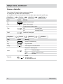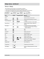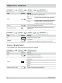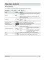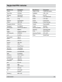
1
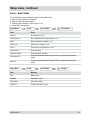
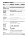
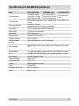
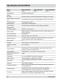
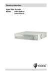
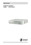
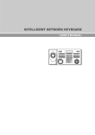
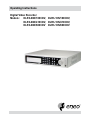
Operating Instructions
Digital Video Recorder
Models: DLR3-08N/160CDV, DLR3-16N/160CDV,
DLR3-08N/410CDV, DLR3-16N/410CDV,
DLR3-08N/660CDV DLR3-16N/660CDV
Safety instructions
EMC class
► This video recorder (DVR) is a class A device in accordance with EN 55022.
► This device may cause interference to other equipment in domestic use. In such cases the persons operating the DVR are required to provide appropriate countermeasures, for which they themselves bear the cost.
Importance of these Operating Instructions
► Please read the safety instructions and the other information contained in the Operating Instructions before
connecting up and operating the DVR.
► The Operating Instructions should be kept in a safe place for later reference.
Ambient conditions for the DVR
► The DVR should be protected against excessive heat, dust, damp and vibration.
► The DVR may only be operated at temperatures between +5°C and +40°C, and up to a maximum air
humidity of 90%.
► The DVR may only be operated indoors, and must be protected against incursion of water and damp.
Care of the DVR
► Never switch on the DVR when damp has penetrated it. In such cases, have the DVR checked by a qualified
service engineer.
► Do not place any heavy objects on the DVR.
► Never cover over the DVR's vents.
► Never insert metal objects or any other items into the vents. This may permanently damage the DVR.
► The housing may only be opened by authorised persons. Repairs may only be carried out by qualified
service personnel.
► The DVR must be disconnected from the power supply before its housing is opened.
Getting started with the DVR
► When laying the connecting cables, make sure no weight is placed on them, that they are not kinked or
damaged, and that no damp can penetrate them.
Cleaning the DVR
► The housing of the DVR may only be cleaned with a damp (not wet) cloth,
► Use only a mild detergent. Do not use solvent-containing detergents or petrol. This could permanently
damage the surface finish.
Spare parts
► Use only original spare parts from Videor Technical GmbH.
DLR3-XXN/XX
Table of contents
Overview
7
Package contents
7
Basic functions
7
Features
7
Requirements for operation
7
Control options
7
Connections on the rear
8
Front panel controls
9
Key to controls
10
Function buttons
10
PTZ camera functions
10
Playback functions
10
Menu structure
11
Getting started
13
Checklist for DVR operation
13
Switching on the DVR
14
Accessing the Setup menu
14
Switching off the DVR
14
Administration
15
Saving your system setup 15
Loading your system setup
15
Deleting recordings
15
Downloading software updates
16
Hiding from specific users
16
Restoring factory defaults
16
Determining the memory requirement of a recording
17
Searching for recordings
18
Using calendar search
19
Using event log search
20
Using text-in search
21
Using motion search
23
Copying recordings
24
Menu descriptions – Setup menu
25
System – Information
26
System – Date/Time
27
System – Storage
28
System – User30
System – Shutdown31
System – Log out USER...31
Network – Network31
Network – Notification
34
DLR3-XXN/XX
Table of contents
Devices – Camera35
Devices – Alarm-Out36
Devices – Display37
Devices – Remote Control38
Record – Record39
Record – Schedule
40
Record – Pre-Event
41
Event – Alarm-In
42
Event – Motion Detection
44
Event – Video Loss
46
Event – Text-In
48
Event – System Event
51
Event – Event Status
53
Specifications DLR3-08N/XX
54
Specifications DLR3-16N/XX
56
Accessories
58
Supported PTZ cameras
59
Index
60
Notes on disposal
63
DLR3-XXN/XX
Overview
Package contents
●
●
●
●
●
●
Digital video recorder (DVR)
Mains power cord
Operating instructions
RAS (Remote Administration System) software on CD
Operating instructions for RAS software on paper and CD
Mounting kit for cabinet installation
Basic functions
●
●
●
●
Record video images using multiple cameras
Even-based recording start
Video playback
Search for specific video sequences
Features
●
●
●
●
●
●
●
●
●
●
●
MPEG-4 compression / duplex mode
8 or 16 loop-through inputs / VGA, FBAS outputs
Alarm inputs / outputs
Max. recording speed: 100 field images per sec (PAL)
Memory capacity 160 GB / 410 GB / 660 GB
Maximum video resolution 720 x 576 pixels
Archiving/image transfer via USB and CD-RW
Live picture & Playback Zoom (2x)
Integral Motion Detector
Telemetry control functions via RS-485 port
Network connection (Ethernet)
Requirements for operation
●
●
●
●
Digital video recorder DLR3 connected
At least 1 camera connected
At least 1 monitor connected
Mouse connected, if DVR is to be controlled by mouse
Control options
● Front panel
● Mouse
● RAS program
DLR3-XXN/XX
Connections on the rear
Note: Connections optionally for NTSC or PAL operation.
2
1
VIDEO IN 1
VIDEO IN 2
VIDEO IN 3
VIDEO IN 4
VIDEO IN 5
VIDEO IN 6
VIDEO IN 7
VIDEO IN 8
VIDEO IN 9
VIDEO IN 10
VIDEO IN 11
VIDEO IN 12
VIDEO IN 13
VIDEO IN 14
VIDEO IN 15
VIDEO IN 16
LOOP1
LOOP2
LOOP3
LOOP4
LOOP5
LOOP6
LOOP7
LOOP8
LOOP9
LOOP10
LOOP11
LOOP12
LOOP13
LOOP14
LOOP15
LOOP16
CAUTION
RISK OF ELECTRIC SHOCK
DO NOT OPEN
AI1 AI2 AI3 AI4 GND AI5 AI6 AI7 AI8 GND
NO
1
12
C
11
NO NC
10
C
NO ARI GND /RX+ /RXTX+ TX-
9
AI9 AI10 AI11 AI12 GND AI13 AI14 AI15 AI16 GND
RS-232C
NETWORK
8
7
VIDEO OUT
VGA
6
5
4
CAUTION: TO REDUCE THE RISK OF ELECTRIC SHOCK,
DO NOT REMOVE COVER (OR BACK).
NO USER-SERVICEABLE PARTS INSIDE.
REFER SERVICING TO QUALIFIED
SERVICE PERSONNEL.
SPOT
No.
Designation
Functions/connections
Example devices
1
VIDEO IN 1-16
Max. 16 video channels
Cameras
2
LOOP 1-16
Max. 16 loop-through video channels
Cameras
3
SPOT
Video output
Spot Monitor
4
VIDEO OUT
Video output
Monitor
5
VGA
PC monitor
PC monitor
6
RS-232C
External interface
Modem
7
NETWORK
Network
Network cable
8
AI1 - AI16
Alarm inputs for external devices
Sensors
9
/RX+, /RX-,
TX+, TX-
External interface (RS-485)
Keyboard, PTZ camera
10
ARI/GND
Reset alarm with external signal
Switch
11
NO, C, NC
Alarm outputs for external devices
Siren, flashing light
12
Reset switch
Reset to factory defaults
-
13
Power supply
Mains power connection
-
DLR3-XXN/XX
Front panel controls
The following diagram and table set out the controls on the front panel of the DVR:
1
1
2
2
3
SPOT
SEQUENCE
DISPLAY
GROUP
4
5
6
7
11
10
9
8
CAMEO
4
MENU
PTZ
5
6
7
8
ZOOM
15
No.
Designation
1
9
10
11
12
13
14
15
16
14
CLIP COPY
PLAYBACK
PANIC
ALARM
1
12
Function
PTZ camera functions (secondary assignment)
2
SPOT, SEQUENCE,
CAMEO, DISPLAY,
GROUP, PTZ, ZOOM,
PLAYBACK, CLIP COPY
Function buttons
3
MENU
Open/quit menu structure (primary assignment)
4
Menu navigation
Navigate and select within the menu structure (secondary assignment)
5
Power-on indicator when DVR is in operation
6
Display at alarm
7
Indicates hard disk operation
8
Connections
USB ports
9
Indicates recordings being copied
10
Indicates Ethernet or modem connection
11
Playback functions (primary assignment)
12
PANIC
Start/end panic recording
13
ALARM
● Reset alarm
● View event list
14
1 to 16
● Select cameras
● Enter passwords
15
DLR3-XXN/XX
Open built-in CD-RW writer
Key to controls
Function buttons
Note: The secondary function assignment is accessed by holding down the key.
Element
Function
Spot monitor assignments (secondary assignment)
Sequence On/Off (secondary assignment)
Cameo mode On/Off (secondary assignment)
Changing the image display modes (primary usage)
Switch displayed group (primary assignment)
PTZ camera functions On/Off (secondary assignment)
Zoom On/Off (primary assignment)
Start playback
Copying recordings
PTZ camera functions
Element
Function
Zoom in
Zoom in
Close-up
Wide-angle
Save preset
Load preset
Playback functions
Element
Function
Frame-by-frame rewind
Fast rewind
Start/pause playback
Fast forward
Frame-by-frame forward
10
DLR3-XXN/XX
Menu structure
The following diagram shows the menu structure:
Display
Camera
PIP
2x2
3x3
4x4
Previous Group
Next Group
Edit Group
Sequence
Freeze
Zoom...
PTZ...
Spot Monitor...
DLR3-XXN/XX
1. CAM1
2. CAM2
3. CAM3
Camera
Spot Monitor...
Exit Group Edit
Speed
Auto Pan
Tour
Pattern
Device Menu
Light
Pump
Wiper
Power
Aux.
Move to Origin
Spot Monitor...
Exit PTZ
Spot Monitor 1
11
Menu structure, continued
The following diagram shows the menu structure:
Setup Menu...
Search
System
Information
Date/Time
Storage
User
Shutdown...
Log out user1...
Network
Network
Notification
Devices
Camera
Alarm-Out
Display
Remote Control
Record
Record
Schedule
Pre-Event
Event
Alarm-In
Motion Detection
Video Loss
Text-In
System Event
Event Status
Go to the First
Go to the Last
Go to the Date/Time...
Calendar Search...
Event Log Search...
Text-In Search…
Motion Search...
Clip-Copy...
Zoom...
Slow Play
x1
x1/2
x1/3
x1/4
x1/6
x1/8
Exit Search
12
DLR3-XXN/XX
Getting started
Checklist for DVR operation
Step
Action
1
Connect peripheral devices as per planned setup.
2
Specify menu language.
Setup Menu... > System > Information
3
Adjust date and time.
Setup Menu... > System > Date/Time
4
Set up user.
Setup Menu... > System > User
5
Set up network and desired notification channels
(optional).
Setup Menu... > Network > ...
6
Register peripherals with DVR.
Setup Menu... > Devices > ...
7
Set up event types and associated responses.
Setup Menu... > Event > ...
8
Set up recording parameters and schedule.
Setup Menu... > Record > ...
DLR3-XXN/XX
Menu path
13
Getting started, continued
Switching on the DVR
Requirement:
● The start-up preparations are complete.
Step
Action
1
Plug in DVR mains plug.
2
Switch on monitor.
Result: System starts up automatically and is ready to use.
Accessing the Setup menu
Requirement:
● The DVR is switched on.
● You have set up a custom user name and password or
you are using the following default access data (only when first accessing the Setup menu):
User name: admin
Password: (blank)
Step
1
2
Action
Open Setup Menu...
Result: Prompt for user name and password.
Menu path
Setup Menu...
Log in as user.
Switching off the DVR
Requirement:
● You have accessed the Setup menu.
Step
1
2
14
Action
Shut down the system.
Result: System shuts down automatically.
Menu path
Setup Menu... > System > Shutdown...
After shutdown, disconnect the mains plug.
DLR3-XXN/XX
Administration
Saving your system setup
You can save your DVR’s setup data, including its network configuration.
Requirement:
● USB memory stick
Step
Action
1
Insert a USB memory stick into one of the USB
ports.
2
Export your setup.
3
Specify a file name.
4
Export your setup.
Menu path
Setup menu... > System > Information >
Setup Export...
Export
Loading your system setup
You can load your stored DVR system setup with or without its network configuration.
Requirement:
● USB memory stick with stored setup
Step
Action
Menu path
1
Insert a USB memory stick into one of the USB
ports.
2
Import your setup.
3
Select the file name and, where appropriate, the
network configuration.
4
Import your setup.
Setup menu... > System > Information >
Setup Import...
Import
Deleting recordings
You can only delete all your recordings together. It is not possible to delete recordings from a specific time
period.
Step
1
Action
Menu path
Delete all recordings.
Setup Menu... > System > Information > Clear All
Data...
or
Setup menu... > System > Storage > Information
tab > Using > Clear
DLR3-XXN/XX
15
Administration, continued
Downloading software updates
You can download software updates for your DVR from a USB memory stick.
Requirement:
● USB memory stick with latest software release
Step
Action
1
Insert a USB memory stick into one of the
USB ports.
2
Start update.
3
Install new release.
Menu path
Setup Menu... > System > Information > Upgrade...
Hiding from specific users
You can hide video images and camera data according to the preset user rights.
Step
Action
Menu path
1
Set camera Covert mode.
Setup Menu... > Devices > Camera > Settings
2
Cancel ‘Covert Camera View' access for
specific users (groups).
Setup Menu... > System > User
Restoring factory defaults
Before restoring the factory defaults, you should export your current system settings in case you need to reimport them later. (see Saving your system setup and Loading your system setup)
Step
Action
1
Shut down the system.
2
Disconnect the mains plug.
3
Push a paper clip into the Reset button (on the rear of the DVR) and hold it there.
4
Plug in the mains plug.
5
Wait for all the LEDs to flash 5 times (about 30 seconds).
6
Withdraw the paper clip.
16
DLR3-XXN/XX
Administration, continued
Determining the memory requirement of a recording
The amount of memory recorded video sequences will take up depends on the following factors:
● Picture quality
● number of images per second
● duration
The memory requirement for 1 camera is calculated by this formula:
Memory requirement = picture size x duration of recording x images per second
Calculation example: CIF resolution (PAL):
Picture
quality
Picture
size
Duration of
recording
Low
2.4 kB
Standard
4.8 kB
High
Very High
Approx. memory space
5 images/s
10 images/s
25 images/s
24 hours
1.04 GB
2.07 GB
5.18 GB
24 hours
2.07 GB
4.15 GB
10.37 GB
9.6 kB
24 hours
4.15 GB
8.29 GB
20.74 GB
14.4 kB
24 hours
6.22 GB
12.44 GB
31.10 GB
2Calculation example: 2CIF resolution (PAL):
Approx. memory space
Picture
quality
Picture
size
Duration of
recording
5 images/s
10 images/s
25 images/s
Low
4.8 kB
24 hours
2.07 GB
4.15 GB
10.37 GB
Standard
9.6 kB
24 hours
4.15 GB
8.29 GB
20.74 GB
High
19.2 kB
24 hours
8.29 GB
16.59 GB
41.47 GB
Very High
28.8 kB
24 hours
12.44 GB
24.88 GB
62.20 GB
DLR3-XXN/XX
17
Searching for recordings
Find first stored recording
Search
Go to the First…
Find last stored recording
Search
Go to the Last…
Find recording by date and time
Search
Go to the Date/Time...
Calendar search
For each camera the calendar search indicates:
● the days from which there are recordings
● the time ranges of recordings on those days
Search
Calendar Search...
Event log search
The event log search enables you to search for events based on specific criteria, such as:
● movements recorded by a specific camera
● alarm from a specific alarm input
● System events
Search
Event Log Search...
Text-in search
The text-in search enables you to search for recordings based on specific text inputs.
Search
Text-In Search…
Motion search
The motion search function can detect movements in recordings within defined zones for one camera. 2 types
of motion search are possible:
● Motion search: Search for movement in a defined zone.
● Museum search: Search for movement of a defined object.
Search
Motion Search...
Copying recordings
Recordings can be written to a CD or copied to a USB memory stick.
Search
18
Clip-Copy...
DLR3-XXN/XX
Using calendar search
Performing a calendar search
Step
1
Action
Menu path
Open calendar search.
Result: Calendar and time line are displayed.
2
Select day and time
3
Confirm input.
Search
Term
Search > Calendar Search...
Go
Calendar Search...
Symbol
Meaning
Date display
● Grey: No recording available
● White: Recording available
Hours display
● White: Recording available
Select a Segment
DLR3-XXN/XX
If the date and time on the DVR have been changed (such
as when switching to Summer time) there may be multiple
recordings for one time from the same camera. They are stored
in separate segments.
19
Using event log search
Performing an event log search
Step
1
2
3
4
Action
Menu path
Open event log search.
Result: The result of the last search is displayed.
Define criteria.
Search > Event Log Search...
Option...
Confirm input.
Result: List of search results is displayed.
Search
Select desired entry from list.
Search
Term
Event Log Search...
Symbol
Option...
Meaning
From First
Start date
To Last
End date
Check Time Overlap
Activates a system prompt if there are multiple recordings
for the same time range
Alarm-In
Alarm inputs in response to which a search for events is
to start
Motion
Cameras on which to search for motion detection
Video Loss
Cameras on which to search for video loss
Text-In
Text input devices on which to search for events
Record Channels
Cameras on which to search for events
Search for system events:
Setup Menu... > Event > System Event > Actions
20
DLR3-XXN/XX
Using text-in search
Performing a text-in search
Step
1
2
3
4
Action
Open text-in search.
Result: The result of the last search is displayed.
Define text inputs.
Confirm input.
Result: List of search results is displayed.
Menu path
Search > Text-In Search...
Option...
Search
Select desired entry from list.
DLR3-XXN/XX
21
Using text-in search, continued
Search
Term
Text-In Search…
Symbol
Option...
Meaning
From First
Start date
To Last
End date
Channels
Text input devices on which to search for events
Type of text input:
Any Text-In Product
Generic Text
Epson
No.
Numbers of text elements to search for
Linking operator for different query conditions:
-
(blank)
AND
OR
Name
Text field by which the search should be made
Comp.
Comparison conditions
Value
Numerical value against which the comparison is to be made
Column
Column number
Line
Line number
+
Add new set of search parameter
Case Sensitive
Makes search case-sensitive
Load
Load saved search option settings
Save
Save current search option settings
22
DLR3-XXN/XX
Using motion search
Performing a motion search
Step
Action
Menu path
1
Display desired camera in single frame.
Display > Camera > ...
2
Open motion search.
Search > Motion Search...
3
Enter settings for motion search.
Option...
4
5
Confirm input.
Search
Result: List of search results is generated.
Select desired entry from list.
Search
Term
Motion Search...
Symbol
Option...
Meaning
From First
Start date
To Last
End date
Type of search:
Type
Zone
Motion Search
Search for movement in a defined zone
Museum Search
Search for movement of a defined object.
Definition of motion-sensitive zones for motion search or museum search:
See “Zone” on page 44.
Sensitivity of motion detection of:
1 (Dull)
Sensitivity
2
3
4
5 (Sensitive)
Min. Blocks
DLR3-XXN/XX
Motion search only (not museum search):
Specify in how many motion-sensitive blocks motion must be detected as
a minimum to trigger an alarm
23
Copying recordings
Copying recordings to CD or USB memory stick
Step
1
2
3
Action
Menu path
Find desired recordings.
Note: Make a note of the data of the recordings you
want to copy.
Search > ...
Define settings.
Search > Clip-Copy...
Start copying.
Result: The recordings are copied.
Search
Term
Data Source
Start
Clip-Copy...
Symbol
Meaning
Record
From First
Start date
To Last
End date
Channels
Assignment of cameras from which recordings are to be copied
Password
Use password, if desired
Destination medium:
Internal CD-RW
Dest.
USB-CD-RW
1. USB Storage
2. USB Storage
3. USB Storage
File name
Name of file on destination medium
Include Text-In
Data
Activates use of Text-In data
Verify After
Burning
Activates verification after burning
Progress
Copy status
24
DLR3-XXN/XX
Menu descriptions – Setup menu
The Setup menu has the following sub-menus:
System menu
On the “System” menu
● the basic settings are made
● users are administered
● the system is shut down.
Network menu
On the “Network” menu the network settings are made. Network access provides
access to all the functions of the DVR via
● RAS (Remote Administration System), independent of Internet Explorer
The DVR can be configured so that alarms trigger a notification by e-mail or notify an
RAS.
Devices menu
On the “Devices” menu the connected peripheral devices are configured. Possible
peripherals are:
● Cameras
● Microphones and speakers (through amplifier)
● Sirens and signal lamps
● Monitors
● Remote control for PTZ
Record menu
On the “Record” menu the following settings are made:
● Recording quality
● Timer control
● Duration of pre-event recording
Event menu
On the “Event” menu the following settings are made:
● Assignment of alarm inputs to alarms
● Configuration of motion-sensitive zones individually for each camera
● Definition of text input device and assignment to alarms
● Response to undesirable events
The event status is additionally displayed.
DLR3-XXN/XX
25
Setup menu
System – Information
On the “Information” menu
● basic information is entered and displayed
● software updates are installed
● recorded data are deleted as required
Setup Menu...
Term
System
Symbol
Information
Meaning
Site
Location of DVR
System ID
ID for remote keypad
● The remote keypad and DVR must be set to the same ID.
Language
Menu language
Version
Version of DVR software
Upgrade...
Starts installing latest version of software via USB port
Import...
Import setup
Export...
Export setup
Show System Log...
Show log of all actions and events
From
Date of oldest recording
To
Date of newest recording
Clear All Data...
Deletes all stored data
26
DLR3-XXN/XX
Setup menu, continued
System – Date/Time
On the “Date/Time” menu
● time and date settings are made
● dates of public holidays are entered
● time synchronisation is configured.
Setup Menu...
Term
System
Symbol
Date/Time
Date/Time
Meaning
Date
Date
Format Date display format
Time
Time
Format Time display format
Time Zone
Local time zone
Use Daylight Saving Time
Activates use of summertime Daylight Saving Time
Setup Menu...
Term
System
Symbol
Date/Time
Holiday
Meaning
No.
Number of entered public holiday
Date
Date of each desired public holiday
Setup Menu...
Term
System
Symbol
Date/Time
Time Sync
Meaning
Automatic Sync.
Activates synchronisation with time server
Time Server
IP address or domain name of time server
Interval
Synchronisation interval
Last Sync-Time
Time of last synchronisation
Run as Server
Activates use of the DVR as the time server
DLR3-XXN/XX
27
Setup menu, continued
System – Storage
On the “Storage” menu the status and usage of the available storage media is displayed.
Setup Menu...
Term
System
Symbol
Storage
Information
Meaning
Type
Type of storage medium
Capacity
Size of storage medium
Format Storage medium usage >>
Information
Time range of recorded data >>
Format
Term
Symbol
Meaning
Use of storage medium:
Use as
Record
Not using
Activating permits:
Partition
CD/DVD burn
Format Reserves a data buffer as a separate
partition. This is essential for burning
CDs, and must be activated for a
storage medium with „Record“ usage.
Formatting deletes the recordings from the hard disk
Information
Term
Symbol
Meaning
From
Start date of recorded data
To
End date of recorded data
Clear
Delete all recordings
28
DLR3-XXN/XX
Setup menu, continued
Setup Menu...
Term
System
Symbol
Storage
Meaning
Type
Memory type
Disk Bad
Data carrier status
Temperature
Temperature status
S.M.A.R.T.
Result of S.M.A.R.T. check
DLR3-XXN/XX
Status
29
Setup menu, continued
System – User
On the “User” menu the user groups and individual users are set up.
Setup Menu...
Term
System
Symbol
User
Meaning
Group & User,
Group field
Assignment of group access privileges
Table of possible group access privileges >>
Group & User,
User field
Set password
+ Group...
Add a new group
+ User...
Add a new user
Set password
Auto Login
User to be logged in automatically
Auto Logout
Time after which logged-in user is automatically logged out
Table of possible group access privileges
Group access privilege
Meaning
Shutdown
May shut down the DVR
Upgrade
May install a new firmware version
System Time Change
May change the time setting
Data Clear
May delete recording data
Setup
May make changes anywhere on the Setup menu
Colour Control
May change the picture settings
PTZ Control
May control PTZ cameras
Alarm-Out Control
May reset alarms
Covert Camera View
May view video images from covert cameras
System Check
May interrogate system status
Record Setup
May make changes to the Record menu
Search
May use Search mode
Clip-Copy
May copy video images
30
DLR3-XXN/XX
Setup menu, continued
System – Shutdown
Setup Menu...
System
Shutdown...
System – Log out USER...
Setup Menu...
System
System – Log out USER...
Network – Network
On the “Network” menu all settings required to ensure network access are made.
Setup Menu...
Term
Network
Symbol
Network
Network
Meaning
Transmission bandwidth:
Transfer Speed
(bps)
bits per second
(ips)
images per second
Quality of picture transmission via network (PAL):
Quality
DLR3-XXN/XX
Very High
14,4 kB/picture
High
9,6 kB/picture
Standard
4,8 kB/picture
Low
2,4 kB/picture
31
Setup menu, continued
Setup Menu...
Term
Network
Symbol
Network
LAN
Meaning
Type of connection to DVR:
Type
Manual
Manual connection required input of:
● IP Address
● Gateway
● Subnet Mask
DHCP
Automatic assignment of IP address of DNS
server
ADSL
(with
PPPoE)
Requires following input as specified by provider:
● ID
● Password
Note: Use of modem must not be activated.
DNS Server
Address of DNS server
Port Number Setup...
Definition of port numbers needed to access the DVR via the
RAS software
Setup Menu...
Term
Enable
Network
Symbol
Network
Meaning
Enables modem use
Note: LAN type ADSL must not be enabled.
Baud Rate
Baud Rate
Data Bit
Number of data bits
Stop Bit
Number of stop bits
Parity
Parity
32
Modem
DLR3-XXN/XX
Setup menu, continued
Setup Menu...
Term
Network
Network
Symbol
DVRNS
Meaning
Use DVR Name Service
Enables the DVR name service
DVRNS Server
IP address or domain name of DVRNS server
DVRNS = Digital Video Recorder Name Service
Port
Port for DVRNS
Use NAT
Enables NAT (Network Address Translation) use
DVR Name
Name by which the DVR is to be registered with the DVRNS
server
Check
Check DVR name for usability after entering
Help Desk
Information from help desk if DVRNS setting correct
DLR3-XXN/XX
33
Setup menu, continued
Network – Notification
On the “Notification” menu the method of notification is defined.
Setup Menu...
Term
Network
Symbol
Notification
Mail
Meaning
Enable
Enables notification by e-mail
SMTP Server
IP address or domain name of SMTP server
Port
Port for SMTP server
Default is port 25.
Authentication
Login to SMTP server
Sender
E-mail address of sender
Recipient
E-mail address of recipient
Setup Menu...
Term
Network
Symbol
Notification
Callback
Meaning
LAN
Enables notification of an RAS via LAN
No.
Number of IP address
IP Address
IP addresses of RAS PCs
Retry
Number of notification attempts by the DVR in the event of an
error
Modem
Enables notification of an RAS via modem
Remote Server Phone
Number
Telephone number of the modem on the notified RAS PC
Outside Line Call
Outside line code for external calls, if DVR’s modem is connected to a PABX system
Callback Phone Number
Telephone number of DVR’s modem
The RAS PC contacts the DVR on this number.
34
DLR3-XXN/XX
Setup menu, continued
Devices – Camera
On the “Camera” menu the cameras are configured.
Setup Menu...
Term
Devices
Symbol
Camera
Settings
Meaning
No.
Activates the cameras
Title
Name of camera
Visibility of recordings and camera data depending on user access
privileges:
Use
Setup Menu...
Term
Normal
All users see all camera data and all recordings
Covert1
Users without relevant access see camera title, status
symbol, but no recordings
Covert2
Users without relevant access see only camera title, but no
recordings
Devices
Symbol
Camera
PTZ
Meaning
No.
Number of camera
Product
PTZ camera type as per specified list
ID
Unique ID of PTZ camera
Port
Interface type of PTZ cameras
Settings as specified by PTZ camera manufacturer:
Baud Rate
Setup…
Data Bit
Stop Bit
Parity
DLR3-XXN/XX
35
Setup menu, continued
Devices – Alarm-Out
On the “Alarm-Out” menu the alarm outputs are configured.
● “Settings” tab: The alarm outputs are configured.
● “Schedule” tab: Time slots are defined in which the alarm outputs respond in specific ways.
Setup Menu...
Term
Devices
Symbol
Alarm-Out
Settings
Meaning
No.
Number of alarm output
Title
Name of alarm output
Contact method of alarm output:
Type
Dwell
Setup Menu...
Term
NO
Normally Open
NC
Normally Closed
Duration of alarm signal
Devices
Symbol
Alarm-Out
Schedule
Meaning
No.
Number of schedule entry
Day
Day of the week
Range
Time range at 15-minute intervals
Response in defined period:
Mode
Channels
36
On
Continuous alarm
Event
Alarm in response to event
Off
No alarm
Enable
● Alarm outputs
● internal beep by DVR
DLR3-XXN/XX
Setup menu, continued
Devices – Display
On the “Display” menu the mode of on-screen display is configured.
● “OSD” tab: Specify what additional information is displayed on-screen.
● “Main Monitor” tab: Specify how the camera images are displayed on the main monitor.
● “Spot Monitor” tab: Specify which cameras are displayed on the spot monitors.
Setup Menu...
Term
Devices
Symbol
Display
Displayed symbol
OSD
Meaning
Progress
Activates display of:
Zoom
Visible when Zoom mode enabled
Network
Visible when DVR operating in a network
Freeze & Sequence
● Freeze
● Visible when Sequence mode enabled
Screen Group
1/4
Free Space
Displays number of groups, and their ID
numbers
● Visible when Recycle mode enabled
● Remaining hard disk capacity, if Recycle
mode not selected
Date
-
Date
Time
-
Time
User Name
-
Display of user name
Camera
Activates display of:
No.
-
Display of camera number
Title
-
Display of camera title
Record
Display of Record symbols
PTZ
Visible when PTZ camera is displayed
Text-In
-
Display of character string
Display Dwell
-
Text In Dwell Time
Transparency
-
Transparency of menu screens
-
Distance of displayed symbols from screen
margin
OSD Margin...
DLR3-XXN/XX
37
Setup menu, continued
Setup Menu...
Term
Devices
Symbol
Display
Main Monitor
Meaning
Modes of sequences in multiple playback:
Mode
Full
Sequence
All cameras are switched through sequentially.
Cameo
Only the image at the bottom right is switched
through; cameras in „Covert“ mode are not
displayed to users without „Covert“ access.
Interval
Time interval between picture refresh
Event Monitoring On
Displays image of relevant camera in full-screen mode when an
event occurs
Setup Menu...
Term
Devices
Symbol
Display
Spot Monitor
Meaning
No.
Number of spot monitor output
Channels
● Cameras
● Display time of recordings from cameras on spot monitor
Devices – Remote Control
On the “Remote Control” menu the remote control function is configured.
Setup Menu...
Term
Port
Devices
Symbol
Remote Control
Meaning
Interface type of remote control
Setup as specified by manufacturer:
Baud Rate
Setup…
Data Bit
Stop Bit
Parity
Remote Control Product
38
Remote control type as per specified list
DLR3-XXN/XX
Setup menu, continued
Record – Record
On the “Record” menu the basic settings for recordings and their quality are made.
Setup Menu...
Term
Recycle
Record
Symbol
Record
Meaning
Enables automatic overwriting of the oldest recordings when the
hard disk is full
Note: If not enabled, recording ends when the hard disk is full.
Quality of recorded images
Resolution
Standard
CIF
High
2CIF
Event Record Dwell
Duration of recording when an event occurs
Auto Deletion
Specify time after which automatically deleted
Use Panic Recording
Enables the panic recording function
Duration of panic recording
Panic Recording Duration
No Limit
End panic recording by pressing PANIC
button
xx min.
Panic recording ends after preset time or
by pressing PANIC button
ips
Number of recorded images per second in panic recording
Quality
Picture quality of the recorded images in panic recording
DLR3-XXN/XX
39
Setup menu, continued
Record – Schedule
On the “Schedule” menu the schedule for recording is defined.
Setup Menu...
Record
Term
Symbol
Schedule On
Schedule
Meaning
Enables schedule entries
Note: A recording is made only if schedule entries are enabled.
Otherwise only panic recording is possible.
No.
Number of schedule entry
Day
Day of the week
Range
Time range at 15-minute intervals
Response:
Mode
Channels
No Record
-
Time
Always record in the defined time slot in the quality
set for “Time” mode
Event
Record only in case of event in the defined time
slot in the quality set for „Event“ mode
Time &
Event
Always record in the defined time slot in the quality
set for “Time” mode, also in case of event in the
defined time slot in the quality set for “Event”
mode
Assignment of cameras to schedule
Picture data settings in Time and Event modes:
Settings
ips
Number of recorded images per second
Quality
Picture quality of recorded images
Picture data defaults in Time and Event modes:
Default
40
ips
Number of recorded images per second
Quality
Picture quality of recorded images
DLR3-XXN/XX
Setup menu, continued
Record – Pre-Event
On the “Pre-Event” menu the settings for recording prior to the event are made.
Setup Menu...
Term
Record
Symbol
Pre-Event
Meaning
No.
Activates the cameras
ips
Number of recorded images per second prior to the event
Quality
Picture quality of the recorded images prior to the event
Recording time prior to the event
Dwell
DLR3-XXN/XX
Note: The pre-event recording memory capacity is limited.
Consequently, the maximum recording time prior to the event,
the number of recorded images and picture quality are interdependent.
41
Setup menu, continued
Event – Alarm-In
On the “Alarm-In” menu the alarm inputs and responses to events are configured.
Setup Menu...
Term
Event
Symbol
Alarm-In
Settings
Meaning
No.
Enables the alarm inputs
Title
Name of alarm input
Contact method of alarm input:
Type
Panic Record
Setup Menu...
Term
NO
Normally Open
NC
Normally Closed
Panic recording of alarm input
Event
Symbol
Alarm-In
Actions 1
Meaning
No.
Number of alarm input
Record
Assignment of cameras to record in event of alarm
These cameras must be in “Event” or “Time and Event” mode
within the time slot:
Setup Menu... > Record > Schedule
Alarm-Out
Assign and enable
● alarm outputs
● internal beep by DVR
These alarm outputs and the internal beep must be enabled
within the time slot:
Setup Menu... > Devices > Alarm-Out > Schedule
Assign and enable notifications:
Mail
Modem
Notify
LAN 1 to LAN 5
Alert Window
The selected function must be enabled:
Setup Menu... > Network > Notification
42
DLR3-XXN/XX
Setup menu, continued
Setup Menu...
Term
Event
Symbol
Alarm-In
Actions 2
Meaning
No.
Number of alarm input
PTZ
Select PTZ cameras to record in event of alarm and select the
desired settings
Spot Monitor
Select spot monitor on which camera image is displayed in
event of alarm
DLR3-XXN/XX
43
Setup menu, continued
Event – Motion Detection
On the “Motion Detection” menu the motion-sensitive zones are defined and responses to events configured.
Setup Menu...
Term
No.
Event
Symbol
Motion Detection
Settings
Meaning
Enables motion detection for the camera
Sensitivity of motion detection:
Sensitivity
Daytime
Nighttime
Select the motion-sensitive blocks within the time slot
Left mouse button functions:
● Click to select/deselect
● Click - hold down - drag to define a zone for selection/deletion/back
Right mouse button functions or menu in time slot to select blocks:
Zone
Min. Blocks
Select
Select complete row of blocks
Clear
Clear selection of a row
Reverse
Reverse selection of a row
Select All
Select all blocks
Clear All
Clear selection of all blocks
Reverse All
Reverse selection of all blocks
Specify in how many motion-sensitive blocks motion must be detected as
a minimum to trigger an alarm:
Daytime
Nighttime
Zone View
Mark the motion-sensitive zones (red in event of motion)
Motion Ignoring
Interval
Time interval between 2 events logged as separate events:
Daytime Setup...
Definition of “Daytime” time range
44
Never
Each motion detection is logged as a separate event.
DLR3-XXN/XX
Setup menu, continued
Setup Menu...
Term
Event
Symbol
Motion Detection
Actions 1
Meaning
No.
Number of alarm input
Record
Assignment of cameras to record in event of alarm
These cameras must be in “Event” or “Time and Event” mode
within the time slot:
Setup Menu... > Record > Schedule
Assign and enable
● alarm outputs
● internal beep by DVR
Alarm-Out
These alarm outputs and the internal beep must be enabled
within the time slot:
Setup Menu... > Devices > Alarm-Out > Schedule
Assign and enable notifications:
Mail
Modem
Notify
LAN 1 to LAN 5
Alert Window
The selected function must be enabled:
Setup Menu... > Network > Notification
Setup Menu...
Term
Event
Symbol
Motion Detection
Actions 2
Meaning
No.
Number of alarm input
PTZ
Select PTZ cameras to record in event of alarm and select the
desired settings
Spot Monitor
Select spot monitor on which camera image is displayed in
event of alarm
DLR3-XXN/XX
45
Setup menu, continued
Event – Video Loss
On the “Video Loss” menu checking for covert cameras and the responses to events are configured.
Setup Menu...
Term
Event
Symbol
Video Loss
Settings
Meaning
Sensitivity of check as to whether camera is covert:
Check Obscuration
Setup Menu...
Term
Event
Symbol
Never
not checked
15
very sensitive
Video Loss
Actions 1
Meaning
No.
Number of covert camera
Record
Assignment of cameras to record in event of alarm
These cameras must be in “Event” or “Time and Event” mode
within the time slot:
Setup Menu... > Record > Schedule
Alarm-Out
Assign and enable
● alarm outputs
● internal beep by DVR
These alarm outputs and the internal beep must be enabled
within the time slot:
Setup Menu... > Devices > Alarm-Out > Schedule
Assign and enable notifications
Mail
Modem
Notify
LAN 1 to LAN 5
Alert Window
The selected function must be enabled:
Setup Menu... > Network > Notification
46
DLR3-XXN/XX
Setup menu, continued
Setup Menu...
Term
Event
Symbol
Video Loss
Actions 2
Meaning
No.
Number of covert camera
PTZ
Select PTZ cameras to record in event of alarm and select the
desired settings
Spot Monitor
Select spot monitor on which camera image is displayed in
event of alarm
DLR3-XXN/XX
47
Setup menu, continued
Event – Text-In
On the “Text-In” menu the text input device is defined and the responses to text input are configured.
Setup Menu...
Term
Event
Symbol
Text-In
Meaning
No.
Number of text input device
Setup
Configuration of text input >>
Title
Name of text input
48
Settings
DLR3-XXN/XX
Setup menu, continued
Setup
Term
Port
Symbol
Meaning
Interface
Setting as specified by manufacturer of text input device (ATM,
cash-till etc.):
Setup…
Baud Rate
Data Bit
Stop Bit
Parity
Type of text input:
Text-In Product
Generic Text
Epson
Transaction Start
Character string with which text input must start for the DVR to
respond
Any Character
DVR responds to any character
Transaction End
Character string with which text input must end for the DVR to
respond
0 more line(s)
Enables recording of n more lines
Line Delimiter
Line delimiter as specified by the text input device manufacturer:
^J for LF or ^M for CR
Ignore String
Character string in the text input which the DVR is to ignore
All transmittable character strings are specified by the text input
device manufacturer.
Case Sensitive
Case sensitivity according to text input device manufacturer’s
specification
Time Out
Waiting time after the last string
DLR3-XXN/XX
49
Setup menu, continued
Setup Menu...
Term
Event
Symbol
Text-In
Actions 1
Meaning
No.
Number of alarm input
Record
Assignment of cameras to record in event of alarm
These cameras must be in “Event” or “Time and Event” mode
within the time slot:
Setup Menu... > Record > Schedule
Assign and enable
● alarm outputs
● internal beep by DVR
Alarm-Out
These alarm outputs and the internal beep must be enabled
within the time slot:
Setup Menu... > Devices > Alarm-Out > Schedule
Assign and enable notifications:
Mail
Modem
Notify
LAN 1 to LAN 5
Alert Window
The selected function must be enabled:
Setup Menu... > Network > Notification
Setup Menu...
Term
Event
Symbol
Text-In
Actions 2
Meaning
No.
Number of alarm input
PTZ
Select PTZ cameras to record in event of alarm and select the
desired settings
Spot Monitor
Select spot monitor on which camera image is displayed in
event of alarm
50
DLR3-XXN/XX
Setup menu, continued
Event – System Event
On the “System Event” menu the self-diagnostics and corresponding messages are configured..
Setup Menu...
Term
Event
Symbol
System Event
Health Check
Meaning
System
System self-diagnostics interval
Check Recording
Setup... . Configuration of schedule >>
Check Alarm-In
Interval and status for checking alarm inputs
Setup
Term
Symbol
Meaning
Schedule On
Enables schedule entries
No.
Number of schedule entry
Day
Day of the week
Range
Time range at 15-minute intervals
Interval
Checking interval
Setup Menu...
Term
Event
Symbol
System Event
Storage
Meaning
Disk Bad Notify
Percentage of bad sectors on hard disk as from which an alarm
is triggered
Disk Almost Full Notify
Percentage hard disk space available as from which “Disk
Almost Full” alarm is triggered
Setup…
Configuration of data media S.M.A.R.T. check
Opens a window in which the frequency rate and time and a
temperature limit (in Celsius or Fahrenheit) for the S.M.A.R.T.
check can be specified.
If the temperature limit is exceeded an alarm is triggered.
For details of your hard disk’s temperature limit refer to the
manufacturer’s manual.
DLR3-XXN/XX
51
Setup menu, continued
Setup Menu...
Term
Event
Symbol
System Event
Actions
Meaning
Events (based on checks):
Event
Alarm-Out
System
System check failed
Panic Record
Panic recording in progress
Check Recording
Recording check failed
Check Alarm-In
Check of alarm inputs failed
Disk Almost Full
Preset limit value for hard disk capacity
reached
Disk Full
Hard disk full
Disk Bad
Preset limit value for number of bad
sectors reached
Disk Temperature
Preset temperature limit reached
Disk S.M.A.R.T.
S.M.A.R.T. check failed
Assign and enable
● alarm outputs
● internal beep by DVR
Note: Not possible for system event and panic recording
Assign and enable notifications:
Mail
Notify
Modem
(not in case of system event)
LAN 1 to LAN 5
(not in case of system event)
Alert Window
(not in case of system event)
The selected function must be enabled:
Setup Menu... > Network > Notification
52
DLR3-XXN/XX
Setup menu, continued
Event – Event Status
The “Event Status” menu indicates the status of all possible events:
● Grey text: Event detection not enabled
● White text: Event detection enabled
● Flashing border: Message – acute event for 5 sec
● Yellow field: Pending event
Setup Menu...
Event
Event Status
Event Status
Term
Event
Alarm-In
At alarm input 1 to 16
Check Alarm-In
Error detected at one of alarm inputs 1 to 16
Motion
Motion detected on camera 1 to 16
Video Loss
Video loss on camera 1 to 16
Text-In
Text input on text input device 1 to 16
Panic Record
Panic recording
Check Recording
On checking the recording
Disk Almost Full
On checking the data medium (only if DVR is not operating in Overwrite
mode)
Disk Full
On checking the data medium (only if DVR is not operating in Overwrite
mode)
Setup Menu...
Event
Event Status
Term
Meaning
Type
Memory type
Disk Bad
Data carrier status
Temperature
Data carrier status
S.M.A.R.T.
Result of S.M.A.R.T. check
DLR3-XXN/XX
Storage
53
Specifications DLR3-08N/XX
Model
DLR3-08N/160CDV
DLR3-08N/410CDV
DLR3-08N/660CDV
EDP No.
71983
71982
71981
Video standard
PAL/NTSC (auto detection)
Remark
-
Event logs
Unlimited number of entries for alarm/event/text messages, loss of signal
Security against unauthorised
use
Key locking, 64 user groups with programmable access (up to 256 users)
Transmission rate
100 images per sec (PAL)
Alarm triggering
E-mail, pager, remote SW (RAS)
Alarm activation
Automatic multi-screen display of alarm images programmable
Remote Control
-
Text display interface
ATM/POS, 10 channels max.
Monitor display
Real-time playback: 25 field images per sec (PAL), 30 field images per sec
(NTSC) per camera
Covert camera mode
Programmable
Time synchronisation
Network time log, network time server
System change log
Up to 5000 entries for login/logout, configuration changes, remote access,
change of signal connection, disk read/write errors
Zoom function
2x
Playback
Frame image, 4-/8-channel split, PIP
Post-alarm recording
Up to 15 minutes
VGA
-
Control interface
RS-485 port for PTZ control (verified logs: eneo-Fastrax, Pelco P/D) or
keyboard connection for remote control
Activity detection
Programmable 16 x 12 (192) grid, 5 sensitivity settings
Simplex/Duplex/Triplex/Pentaplex mode
Duplex
Video inputs
8x 1 Vp-p, (F)BAS, 75 Ohm, BNC, loop-through
Monitor outputs
1x spot output 1 Vp-p, (F)BAS, 75 Ohm, BNC
Video output
1x 1 Vp-p, (F)BAS, 75 Ohm, BNC; 1x S-VHS, S= 1 Vp-p, C= 0.3 Vp-p, 75
Ohm
Resolution
720 x 576 pixels (display)
Compression method
MPEG-4, higher compression rates with same picture quality enable maximum recording times
Recording speed
100 field image per sec at CIF resolution (336 x 272 pixels/PAL), 50 field image per sec at 2CIF resolution (672 x 272 pixels/PAL)
Picture size
Basic: 2/2.4 kB; Standard: 4/4.8 kB; High: 8/9.6 kB; Very high: 12/14.4 kB
(NTSC/PAL). 2 times larger in High Resolution mode
54
DLR3-XXN/XX
Specifications DLR3-08N/XX, continued
Model
DLR3-08N/160CDV
DLR3-08N/410CDV
DLR3-08N/660CDV
Hard disk capacity
160 GB ATA hard disk,
expandable to as many
as 3 internal hard disks
410 GB ATA hard disk,
expandable to as many
as 3 internal hard disks
660 GB ATA hard
disks
Playback speed
25 half-screen images per sec at CIF resolution (336 x 272 pixels/PAL) and
Duplex
Export of picture data
via USB 2.0, CD writer.
Network data export: Clip Player, AVI, JPG, BMP
Alarm inputs
8x TTL, programmable as NC/NO (terminal strip)
Alarm outputs
2x relay output (terminal strip)
Alarm reset
1x TTL (terminal strip)
Alarm messages
System error, hard disk error
Pre-alarm recording
Up to 30 minutes
Recording medium
ATA-2 (EIDE) hard disks, built-in CD-RW writer
Archiving
-
Menu languages
German, English, Italian, French, Spanish, Polish, Russian, Czech, Hungarian
Ethernet port
10Base-T, 100Base-TX, RJ-45
Remote software
For remote administration and image search function (RAS plus included)
Ports
2x USB, 1x RS-485, 1x RS-232 (remote control/configuration or modem)
Power Supply
100 VAC~230VAC, 50/60Hz
Power consumption
approx. 150 W
Temperature range
5°C to 40°C
Housing
Metal with plastic front panel
Colour
Pantone 427C
Dimensions (H x W x D)
88 x 430 x 393 mm
Weight
approx. 7.4 kg
DLR3-XXN/XX
55
Specifications DLR3-16N/XX
Model
DLR3-16N/160CDV
DLR3-16N/410CDV
DLR3-16N/660CDV
EDP No.
71984
71985
71986
Video standard
PAL/NTSC (auto detection)
Remark
-
Event logs
Unlimited number of entries for alarm/event/text messages, loss of signal
Security against unauthorised
use
Key locking, 64 user groups with programmable access (up to 256 users)
Transmission rate
100 images per sec (PAL)
Alarm triggering
E-mail, pager, remote SW (RAS)
Alarm activation
Automatic multi-screen display of alarm images programmable
Remote Control
-
Text display interface
ATM/POS, 10 channels max.
Monitor display
Real-time playback: 25 field images per sec (PAL), 30 field images per sec
(NTSC) per camera
Covert camera mode
Programmable
Time synchronisation
Network time log, network time server
System change log
Up to 5000 entries for login/logout, configuration changes, remote access,
change of signal connection, disk read/write errors
Zoom function
2x
Playback
Frame image, 4-/9-/16-channel split, PIP
Post-alarm recording
Up to 15 minutes
VGA
-
Control interface
RS-485 port for PTZ control (verified logs: eneo-Fastrax, Pelco P/D) or
keyboard connection for remote control
Activity detection
Programmable 16 x 12 (192) grid, 5 sensitivity settings
Simplex/Duplex/Triplex/Pentaplex mode
Duplex
Video inputs
16x 1 Vp-p, (F)BAS, 75 Ohm, BNC, loop-through
Monitor outputs
1x Spot-Outputs 1Vss, (F)BAS, 75 Ohm, BNC
Video output
1x 1 Vp-p, (F)BAS, 75 Ohm, BNC; 1x S-VHS, S= 1 Vp-p, C= 0.3 Vp-p, 75
Ohm
Resolution
720 x 576 pixels (display)
Compression method
MPEG-4, higher compression rates with same picture quality enable maximum recording times
Recording speed
100 field image per sec at CIF resolution (336 x 272 pixels/PAL), 50 field image per sec at 2CIF resolution (672 x 272 pixels/PAL)
Picture size
Basic: 2/2.4 kB; Standard: 4/4.8 kB; High: 8/9.6 kB; Very high: 12/14.4 kB
(NTSC/PAL). 2 times larger in High Resolution mode
56
DLR3-XXN/XX
Specifications DLR3-16N/XX, continued
Model
DLR3-16N/160CDV
DLR3-16N/410CDV
DLR3-16N/660CDV
Hard disk capacity
160 GB ATA hard disk,
expandable to as many
as 3 internal hard disks
410 GB ATA hard disk,
expandable to as many
as 3 internal hard disks
660 GB ATA hard
disks
Playback speed
25 half-screen images per sec at CIF resolution (336 x 272 pixels/PAL) and
Duplex
Export of picture data
via USB 2.0, CD writer.
Network data export: Clip Player, AVI, JPG, BMP
Alarm inputs
16x TTL, programmable as NC/NO (terminal strip)
Alarm outputs
2x relay output (terminal strip)
Alarm reset
1x TTL (terminal strip)
Alarm messages
System error, hard disk error
Pre-alarm recording
Up to 30 minutes
Recording medium
ATA-2 (EIDE) hard disks, built-in CD-RW writer
Archiving
-
Menu languages
German, English, Italian, French, Spanish, Polish, Russian, Czech, Hungarian
Ethernet port
10Base-T, 100Base-TX, RJ-45
Remote software
For remote administration and image search function (RAS plus included)
Ports
2x USB, 1x RS-485, 1x RS-232 (remote control/configuration or modem)
Power Supply
100 VAC~230VAC, 50/60Hz
Power consumption
approx. 150 W
Temperature range
5°C to 40°C
Housing
Metal with plastic front panel
Colour
Pantone 427C
Dimensions (H x W x D)
88 x 430 x 393 mm
Weight
approx. 7.4 kg
DLR3-XXN/XX
57
Accessories
EDP No.
Short description
71857
250GB hard disk for DLR/DXR/DTR and DCR
71919
500GB hard disk for DLR/DXR/DTR and DCR
74088
System keyboard with 3-axis joystick
74092
System keyboard with joystick, 5” monitor
71902
USB mouse for DVR series DXR, DLR3
58
DLR3-XXN/XX
Supported PTZ cameras
Manufacturer
Designation
Manufacturer
Designation
Costar
CDC 2500
Ademco Video
Orbiter Microsphere
Dyna Color
CDC2400
SysMania
ORX_1000
Chilsung
CRD-J6416
Linlin
PIH-717
Fine
CRR-1660s
ELMO
PTC-200C/CVAS
Pelco
D-log
ELMO
PTC-250C
Dennard
Dennard2060
Pacom
Pacom 2036
Tokina
DMP-1223
Dongyang
Power Controller
Dongyang Unitech
DRX-500
Sungjin
Receiver/MPU
Dongyang
DY-255RXC
Costar
SIC722V
Sensormatic
Delta Dome II/Ultra IV
Samsung Techwin
SPD 1600
Eneo
Fastrax
Samsung
Samsung Dome
Philips
G3 Basic AutoDome
Pelco
Spectra Dome
LG Honeywell)
GRU604A
Samsung Techwin
SRX-100B
JVC
TK-S576
Hitron
Speed Dome
Sensormatic
Ultra VI
Canon
VC-C4
Canon
VC-C50i
Inter-M
VRX-2201
Vicon
Vicon
Hitron
22x AF Zoom
360Vision
VisionDome
Panasonic
WJ-SX550A
Panasonic
WV-CS850/854
CBC
ZC-SD622J
Samsung
Zoom Camera
Honeywell
HDC-655
LG Honeywell
HSD-25X
Honeywell
HSDN-251
Idis
IRX-100
Ultrak
KD6
Ultrak
KD6 Z-series
Kalatel
KTD-312
LG
LPT-A100L
Novus-C
Samsung
DLR3-XXN/XX
MRX-1000
59
Index
A
D
Accessories 58
Alarm
Configuring inputs 42
Configuring outputs 36
Connecting inputs 8
Connecting outputs 8
Motion Detection 45
Resetting 9
Setting schedule for outputs 36
Setting signal duration 36
Ambient conditions 3, 55
Assigning cameras
Alarm-In 42
Motion Detection 44, 45
Text-In 50
Video Loss 46
Assigning PTZ cameras
Alarm-In 43
Motion Detection 44, 45
Text-In 50
Video Loss 47
Date setting 27
Defining group access rights 30
Defining motion-sensitive zones 44
Display
Configuring 37
Hiding 16, 35
Displaying event status 53
Disposal 63
DVRNS
Network configuration 33
Dwell 36
B
Basic functions 7
C
Calendar search 19
Cameo 38
Cleaning 3
Clip-Copy 24
Configuring a pre-event 41
Configuring event responses 42
Configuring Motion Detection 44
Configuring panic recording 39
Configuring PTZ cameras 35
Configuring remote control 38
Configuring text input as event 48
Configuring the cameras 35
Configuring video loss as event 46
Connecting cameras 8
Connections 8
Control options 7
Control protocols 59
Controls
Front panel 9
Copying recordings 24
Covert mode 16, 35
60
E
E-mail Notification 34
EMC class 3
Enabling notification
Alarm-In 42
Motion Detection 45
System Event 52
Text-In 50
Video Loss 46
Event
Configuring a pre-event 41
Configuring responses 42
Defining motion-sensitive zones 44
Displaying status 53
Setting recording time 39
System events 51
Text input 48
Video Loss 46
Event log 20
F
Front panel 9
Controls 9, 10
G
Getting started
Video recorder 3, 13
H
Health Check 51
I
IP Address 32, 33
DLR3-XXN/XX
Index, continued
L
S
LAN
Network configuration 32
Safety instructions 3
Schedule
Setting for alarm 36
Setting for recording 40
Search
Calendar search 19
Event log 20
Motion Search 23
Text-In 21
Setting a password 30
Setting automatic overwrite 39
Setting menu language 26
Setting recording quality 39
Setting system ID for remote control 26
Setting the duration of records in an event occurrence 39
Setting up a concealed camera 16, 35
Setting up Notification 34
Setting up user groups 30
Setting up users 30
Setup menu
Access 14
Menu descriptions 25
Shutdown 14
Software updates 16
Software version 26
Specifications 54
Specifying public holidays
27
Spot Monitor
Assigning a camera 38
Connecting 8
Storage media
Displaying status 28
Displaying usage 28
Setting automatic overwrite 39
Switching off 14
Switching on 14
System
Export setup 26
Import setup 26
Logging out as USER 31
Shutdown 31
System events
Configuring 51
Health Check 51
M
Memory requirement
Recording 17
Memory type 28
Menu descriptions
Search menu 18
Setup menu 25
Menu structure 11
Modem
Network configuration 32
Monitor
Configuring display 37
Configuring display sequence 38
Connecting 8
Motion Search 23
N
Network configuration 31
Network settings
DVRNS 33
LAN 32
Modem 32
P
Package contents 7
PANIC 9, 39
PTZ cameras
Connecting 8
Supported cameras 59
R
Recording
Copying 24
delete 15
Memory requirement 17
Search 18
Setting schedule 40
Recreate factory settings 16
Recycling the device 63
Remote control
Setting system ID 26
Reset 8, 16
DLR3-XXN/XX
61
Index, continued
T
Text-in search 21
Time
Setting 27
Synchronising 27
62
DLR3-XXN/XX
Notes on disposal
Correct disposal of this DVR
WEEE (Waste Electrical & Electronic Equipment)
Applicable in the member states of the European Union and other European countries with a separate collection system
The marking on the DVR and on the documentation stipulates that it must not be
thrown away in normal domestic waste at the end of its useful life.
General rules
► Avoid uncontrolled waste disposal: Please dispose of this DVR separately from other waste, so as to avoid
posing a hazard to the environment and to human health.
► Recycle the DVR in order to aid the sustainable reuse of material resources.
Private users
► Contact the retailer from whom you purchased the DVR or your competent local authority to find out how
you can recycle the DVR in an environmentally friendly way.
Commercial users
► This DVR must not be thrown away with trade waste. To clarify the conditions of disposal, check your
purchase contract or contact your supplier.
DLR3-XXN/XX
63
eneo® is a registered trademark of Videor Technical E. Hartig GmbH
Exclusive distribution through specialised trade channels only.
VIDEOR TECHNICAL E. Hartig GmbH Carl-Zeiss-Str.
8 · 63322 Rödermark, Germany Tel.
+49 (0) 6074 / 888-0 · Fax +49 (0) 6074 / 888-100
www.videortechnical.com
Operating Instructions version 01/2008 (V1.2)
Subject to technical change without notice.
© Copyright by VIDEOR TECHNICAL 2008