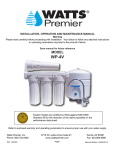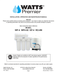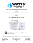
1
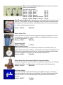
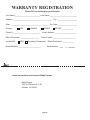
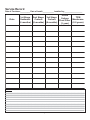
INSTALLATION, OPERATION AND MAINTENANCE MANUAL
Warning
Please read carefully before proceeding with installation. Your failure to follow any attached instructions
or operating parameters may lead to the product’s failure and possible damage to property.
Save manual for future reference
MODELS
5 SV DELUXE
RO-TFM-4SV
WATTS PREMIER 25
RO-TFM-5SV
CRO-TFM-5SV
PUR-TEK
ULTRA 5
System Tested and certified by NSF International against ANSI/NSF
Standard 58 for the reduction of claims specified on performance data sheet.
Refer to enclosed warranty for operating parameters to ensure proper use with your water supply.
Watts Premier, Inc.
Phone: 800-752-5582
1725 W. Williams Drive C-20
www.wattspremier.com
Page 1
Phoenix, AZ 85027
Fax: 623-931-0191
Thank you for your purchase of a Premier Reverse Osmosis system. With proper installation and maintenance, this system will provide you with high quality water for years to come. All of Premier's water enhancement products are rigorously tested by independent laboratories for safety and reliability. If you have any
questions or concerns, please contact our customer service department at 1-800-752-5582 (outside USA
623-931-1977) or refer to our online troubleshooting at www.wattspremier.com.
Table of Contents
Operational Parameters ........................................................................................................................ 4
Contents of Reverse Osmosis System .................................................................................................. 4
Tools Recommended For Installation ..................................................................................................... 4
Drill a Hole for the Faucet in a Porcelain Sink ........................................................................................ 5
Punch a Hole for the Faucet in a Stainless Steel Sink ............................................................................ 5
Faucet Installation ................................................................................................................................. 6
Adapta Valve Installation ....................................................................................................................... 7
Reverse Osmosis Module Mounting ...................................................................................................... 7
Drain Saddle Installation ........................................................................................................................ 8
Tank Tee Installation............................................................................................................................... 8
Green Tube Connection ........................................................................................................................ 9
Blue Tube Connection ........................................................................................................................... 9
Black Tube Connection ....................................................................................................................... 10
Red Tube Connection .......................................................................................................................... 10
6” Final Filter Installation ...................................................................................................................... 10
10" Final Filter Installation ..................................................................................................................... 11
Start up Instructions ............................................................................................................................. 12
6 Month System Maintenance.............................................................................................................. 13
Annual Maintenance ............................................................................................................................ 14
Membrane Maintenance ...................................................................................................................... 15
Check Air Pressure in the Tank ............................................................................................................ 16
5 Stage Reverse Osmosis System ...................................................................................................... 19
California Certification ........................................................................................................................ 21
Other Products from Watts Premier ..................................................................................................... 22
Warranty Registration .........................................................................................................................................25
Service Record ................................................................................................................................... 27
Limited Warranty .................................................................................................................................................28
Page 2
Operational Parameters
Do not use with water that is microbiologically unsafe or of unknown quality, without adequate
disinfection before or after the system.
Operating Temperatures:
Maximum 100°F (37.8°C)
Minimum 40°F 4.4°C)
Operating Pressure:
Maximum 100 psi (7.43 g/cm2)
Minimum
pH Parameters:
Maximum 11
Minimum 3
Iron:
Maximum 0.2 ppm
TDS (Total Dissolved Solids):
< 1800 ppm
Turbidity:
< 5NTU
40 psi (2.80 kg/cm2)
Hardness: Recommended hardness not to exceed 10 grains per gallon, or 120ppm. System will operate
with hardness over 10 grains but the membrane life may be shortened. Addition of a water softener may
lengthen the membrane life.
Note: The operating pressure in your home should be tested over a 24 hour period to attain the
maximum pressure. If it is above 100 psi then a pressure regulator will be required.
Note: Reverse Osmosis water should not be run through copper tubing as the purity of the water will
leach copper and cause an objectional taste in water and cause pin holes to form in tubing. Be sure to
follow any state or local regulations.
Contents of Reverse Osmosis System
5 Stage RO System has 3 bowls. 4 Stage RO System has two bowls.
1 Tank – Blue or White
1 Module – Blue or White
1 Parts Bag – With a 6" or 10" Final Filter
1 Faucet Bag
1 Manual and Warranty Card
If any of the items are missing please contact Premier prior to installing.
Tools Recommended For Installation
√ 1 1/4" Hole Saw Bit for Faucet opening
√ Round Knock out Punch for Stainless Sinks, ½” & 1 ¼”
√ Adjustable Wrench
√ Sharp Knife
√ 1 / 2" - 5/8" Open End Wrenches
√ Phillips Screw Driver
√ Needle Nose Pliers – Adjustable Pliers
√ Electric Drill
√ 1/8", 1/4" & 3/8" Drill Bits
Page 3
Drill a Hole for the Faucet in a Porcelain Sink
Note:
Porcelain sink surface material is extremely hard and can crack or chip quite easily. Use
extreme caution when drilling. Premier Manufactured Systems accepts no responsibility for
consequential damage resulting from the installation of faucet.
A dripping or gurgling sound may be heard coming from the Air Gap hole in the faucet when the
system is running. This is normal and in compliance with UPC Plumbing Codes.
Most sinks are predrilled with 1 ½" or 1 ¼" diameter holes (if you are already using it for a
sprayer or soap dispenser, see step 1).
See the Faucet Installation section for the proper size hole to drill for a non air gap faucet.
Step 1
Determine desired location for the faucet on your sink and place a piece
of masking tape on location where the hole is to be drilled. Mark the
center of the hole on the tape.
Step 2
Using a variable speed drill on the slowest speed, drill a 1/8" Pilot
hole through both porcelain and metal casing of sink at the center of the
desired location. (If drill bit gets hot it may cause the porcelain to crack
or chip).
Step 3
Using a 1 ¼" hole saw, proceed to drill the large hole. Keep drill speed
on the slowest speed and use lubricating oil or liquid soap to keep the
hole saw cool during cutting.
Step 4
Make sure the surroundings of the sink are cooled before mounting the
faucet to the sink after drilling. Remove all sharp edges with a file.
Punch a Hole for the Faucet in a Stainless Steel Sink
Note:
If mounting faucet to a Stainless Steel Sink you will need a ½" & 1 ¼"
Hole Punch. The faucet opening should be centered between the
back splash and the edge of the sink, ideally on the same side as the
vertical drain pipe.
Step 5
Drill a ¼” pilot hole. Use a ½” Hole Punch and an adjustable wrench
to punch the hole in the sink.
The faucet can now be installed.
Page 4
Wave Faucet Installation
Note:
Step 6
If using the Wave Air Gap Faucet (included), a 1 1/4" hole will be required.
If using a Wave non air gap faucet, a 3/4” hole will be required.
Gather and identify the Wave faucet pieces.
• Faucet assembly
• Black Shank Nut
Air Gap Faucet
• Spacer
• Gasket
•
•
Non Air Gap Faucet •
•
•
Faucet assembly
Black Shank Nut
Slotted washer
Gasket
3' Blue Tube
Step 7
Remove black stem nut and insert the three tubes (air gap faucet)
through the white gasket with the groove on the gasket toward the
faucet base.
Step 8
Insert the three tubes through the 1 1/4" hole in the sink. The white gasket
must be on top side of the sink.
Step 9
View from under the sink and insert the white plastic spacer as shown. (A
slotted washer is used if it is a non air gap faucet.)
Step 10
Thread the black stem nut back onto the white threaded stem and thighten
within ¼” of plastic spacer. Check the orientation of the faucet above the
sink and tighten the black plastic washer until white plastic spacer is snug
and faucet stands securely on top of the sink. (For a non air gap faucet,
the blue tube will have to be pushed into the faucet fitting at the bottom of
the faucet. Push the tube all the way to the “tube stop” inside the fitting.)
Note:
A dripping or gurgling sound may be heard coming from the air gap hole
on the faucet or the drain when the system is running. This is normal and
in compliance with UPC (Universal Plumbing Code).
Page 5
AG-SS with Monitor Faucet Installation
Note: If using the AG-SS Monitor Air Gap Faucet , a 1 1/4" hole will be
required.
Step 6
Gather and identify the M-500 faucet pieces.
Step 7
Remove Faucet and small parts from plastic bag.
Slip the Gasket over the threaded Stem to the Faucet Flange.
From above the sink, feed the tubing and Faucet Stem down
through the 1¼ inch mounting hole in the Sink.
Step 8
From below the sink, slide the Tubing Guide up the threaded Stem
and follow it with the Mounting Nut, turning the nut clockwise until
fully tightened.
Step 9
Press the blue colored Product Water Tubing, coming
from the RO purification system into the end of the
threaded Stem. Push it all the way in and then pull on it
firmly to verify it is locked in place.
Step 10
Step 11
Refer to Black Tube Connection and Red Tube
Connection steps in this manual to complete the faucet
installation.
.Remove the Spout from the top of the Faucet by pulling it straight
upward. SEE DRAWING
Remove the Faucet Knob by pinching the two locking tabs inward
and then pulling upward on the Knob while the tabs are pinched
inward. Push the coin cell Battery into the Battery Holder behind the
Circuit Board. NOTE: the + side of the Battery goes against the
Gold metal bracket.
Step 12
Replace the Knob by centering it over the Faucet and aligning the
trough on the inside of the Faucet Knob with the Valve Lever.
Lower the Knob making sure the Valve Lever slides into the trough,
making sure the Knob top hole is centered over the locking tabs.
Push the Knob all the way down until it locks in place.
Push the Spout back into the top of the Faucet so that it is fully
seated and push the frosted Deflector down until fully seated. You
may have to rotate the Deflector until it is in position to be fully
seated.
Step 13
With the Knob rotated to the Right about ½ inch, turn the source
water to your RO purification system on and check for leaks. You
should see the Green light flash at the base of the Faucet while water
is flowing through the Faucet (red light may flash when system is
initially producing water, this will turn green following the
initial tank flush). When you see the Red light flash, it means it is
time to replace your filter cartridge(s).
Turn the Knob to the left until water stops flowing and check for leaks.
Note:
A dripping or gurgling sound may be heard coming from the air gap hole on the faucet or
the drain when the system is running. This is normal and in compliance with UPC
(Universal Plumbing Code) requirements.
Page 6
Adapta Valve Installation
Configuration for 3/8”
compression fittings
Configuration for 1/2”
compression fittings
Step 11
Turn off the cold water supply to the faucet by turning the angle stop valve
completely off.
Step 12
Attach adapta valve as illustrated in the three photos above, choosing the
configuration that fits your plumbing. (When attaching the adapta valve to
straight pipe threads, use Teflon tape on the treads.) The green tube from inlet side of RO
module will be cut to length and attached later in the installation.
Caution: Watersupply line to the system must be from the cold water supply line. Hot water will
severely damage your system.
Reverse Osmosis Module Mounting
Step 13
Note:
Determine best location for the RO module to be mounted to allow for
future system maintenance. The parts bag has 2 self tapping screws.
Using a phillips screwdriver, screw them into the cabinet wall 10 ¾”
apart and 16" from the bottom of the cabinet.
Do not cut these tubes at this time
Page 7
Drain Saddle Installation
Drain Saddle fits standard 1 ¼” – 1 ½” drain pipes
Step 14
Step 15
Gather the pieces of the drain saddle
1 Black compression nut
1 Semi-circle bracket with opening
2 Screws
1 Foam washer
2 Nuts for screws
1 Semi-circle bracket
The small square black foam gasket with a circle cut out of the middle
must be applied to the inside of the drain saddle. Remove sticky tape
backing and stick to the drain saddle as shown.
Step 16
Drill a ¼” hole through the drain pipe at least 1 ½” above the nut of
the P-trap to allow for the removal of the P-trap if necessary.
Assemble the drain saddle around the drain pipe. Position the
drain saddle over the drilled hole in pipe. Insert screw driver into
the opening of the drain saddle and align with drilled hole in drain
pipe. Using Philips screw driver tighten screws evenly and
securely on both sides of the drain saddle. Attach black
compression nut, but do not tighten at this time. The black tubing
will be installed later.
Caution:
Do not over tighten the screws. It may crack the drain saddle.
Tank Tee Installation
Step 17
Teflon tape must be applied in a clockwise direction. Wrap (7 to 12
turns) around the male pipe threads (MPT) on the Stainless Steel
fitting on top of the tank.
Step 18
Thread the brass tee (supplied in the parts bag) onto the brass
connection on the top of tank. Tighten using an adjustable wrench.
Caution: Do not teflon tape the compression fitting threads. If taped it will leak.
Page 8
Green Tube Connection
Step 19 Drape the green tube connected to the 90° Inlet white plastic elbow on the left side of the
Reverse Osmosis Module over to the adapta valve attached to the cold water sink faucet or
attached to the Angle Stop Valve, leaving a gentle curve in the tubing. Cut to desired
length using a sharp knife.
Step 20 Remove a brass nut, plastic delrin sleeve and brass insert from
the parts bag. Place nut on the tube first, then the Delrin sleeve
and then insert the brass Insert into the end of the tube. (Small
taper end of Delrin sleeve must point to the end of tube).
Step 21
Insert the green tube into the ¼” opening until it stops. Slide nut
and sleeve down and thread onto the male pipe threads. Use a
½” wrench to securely tighten.
Blue Tube Connection
Step 22
Position tank in desired location. Stand it upright or lay it on its
side (using the black plastic stand). Measure the blue tube from
the RO module over to the tank and cut it to length.
Step 23
Push blue tube into the brass tee until it stops. Slide brass nut and
plastic Delrin sleeve down until you can thread nut onto the tee.
Use wrench to securely tighten the nut.
Page 9
Black Tube Connection
Note:
The tubing must be as SHORT and STRAIGHT as possible, making a downward slope from
faucet to drain saddle to allowfor proper drainage.
Step 24
Measure the black tube from faucet to the black drain
saddle and make a straight cut with a sharp knife
though tube.
Step 25
Remove black plastic nut from drain saddle. Slip black tube
through black nut. Insert black tube into the opening in the
drain saddle and tighten the black nut securely.
Note:
This is a gravity fed line, if there is any bend in the tube the
rinse water will not flow into the drain properly. Water will back
up and come out the air gap hole in the back of the faucet
base.
Red Tube Connection
Step 26
Using the white plastic union in the parts bag, determine where
the red tubing from the faucet and the black tubing from the RO
membrane housing would join together comfortably. Cut the
tubes leaving a straight cut on both tubes. Insert the red tube in
one end of the white plastic union and the black tube in the other
end. Use a 5/8" wrench to tighten both of the white plastic nuts
securely.
6” Final Filter Installation
Step 27
Gather the pieces needed for the Final Filter installation. Each
unit is supplied with a final filter and 2 white plastic connectors.
Step 28
Remove the blue caps from the final filter.
Page 10
Step 29
Thread the 2 white plastic connectors into the final filter and tighten.
Step 30
To install the 6" filter cut the blue tube from the faucet approximately
in half. Insert the blue tube attached to the faucet into the “out” port
of the filter. The flow arrow should be pointing toward the faucet.
Take the left over section of blue tube and insert it into the other
white connector. Tighten the white compression nuts with a 5/8"
wrench.
Step 31
Slip the brass nut over blue tubing from faucet, then slip the white
Delrin sleeve over the tubing and insert the brass insert into the end
of the blue tubing. (Same as in the Green Tube Connection section.)
Step 32
Insert the tubing into the brass tank tee until it stops. Slide the brass
nut and delrin sleeve along the tube until you can thread the nut onto
the tank tee. Use a ½” open end wrench to tighten the nut securely.
10" Final Filter Installation
Note:
If the system has a 6" final filter, refer to the 6” inch final filter
installation. If the 6" final filter has already been installed skip this
section.
Step 33 Remove the 2 blue caps from the 10" final filter and attach a plastic
connector to each end of the filter.
Snap the 2 white clips from the parts bag onto the top of the
membrane vessel. Snap the 10" final filter into the clips.
Step 34
Measure the blue tube from the faucet to the end of the 10" final filter
that the flow arrow points toward. Use a sharp knife to make a
straight cut through the tubing. Insert the tube into the white
connector and tighten with a 5/8" wrench.
Page 11
Start up Instructions
Note:
If unit is supplied with GAC Carbon Filters (hard plastic case) you will need to start at step # 1
in this section. If unit is supplied with Carbon Block Filters (mesh covering) you may skip to
Step 4 of this section.
Step 1
Disconnect the green tube that runs from the 3rd Stage Filter Housing to the Automatic Shut- Off
Valve and place it in a bucket.
Step 2
Turn on the cold water supply and allow water to flow into the bucket until the water is clear (as
shown in the 6 month System Maintenance section steps 10 and 11.) Then turn off the
incoming water supply.
Step 3
Reconnect the green tube to the Automatic Shut-Off Valve and tighten with 5/8" wrench. (If the
system is hooked up to an Ice Maker see the note below.)
Step 4
Turn on the incoming cold water. Check the system for leaks and tighten any fitting as
necessary. (Check over the next 24 hours to ensure no leaks are present).
Step 5
Open the RO faucet and leave it open until water begins to trickle out. (it will come out slowly)
Step 6
The tank will take between 4 to 6 hours to fill completely (depending on the size of the
membrane, local water temperature and pressure). After the Tank has filled, open the RO
Faucet and flush the Tank completely and to remove carbon particles from final filter.
There is an average of 4 gallons of reject water for every 1 gallon of product water produced.
Note:
If system is hooked up to an Ice Maker, turn Ice Maker off until tank has filled, then flushed and
refilled before allowing water to flow to Ice Maker. The system should have a ball valve
installed before the Ice Maker so it can be closed to prevent water flowing to the Ice Maker.
Your tank must be allowed to fill up in order for the unit to shut off. (If you are installing an Ice
Maker Kit, tee off after the final filter).
Step 7
Fill out postage paid warranty card (phone no. is necessary for registration) and drop it in the
mail. Premier uses this information to provide a free filter change reminder service. Pre-filters
should be changed every six months. You may also register your warranty via our website at
www.wattspremier.com or call 1-800-752-5582 (within USA only).
Step 8
Inspect the reverse osmosis system periodically to ensure the unit is functioning properly.
Page 12
6 Month System Maintenance
Items needed:
√ One 10” sediment filter
√ Two 10” carbon filters
√ Bucket to catch water from filter housings.
√ Wrench to loosen filter bowls. (Watts Premier also sells a double sided wrench).
Step 1
Turn off incoming water supply to the RO at needle valve on adapta valve.
Step 2
Open RO Faucet to allow the water to drain from tank until completely empty. Water can
be saved in a container for drinking or to rinse system parts.
Step 3
Let system sit for 10 – 15 minutes after tank is empty to depressurize before attempting to
remove filter housings.
Step 4
For more leverage, leave RO module attached to wall of cabinet. If you are
unable to access the module you may remove it to change filters. Starting
with the closest housing, remove and empty water, then discard filters.
Continue on to the 2nd and/or 3rd Bowls.
Step 5
Clean all filter housings (bowls) with a mild soap solution and rinse with
water. Check O-rings and lubricate with water soluble lubricant. KY Jelly®
and other water based lubricants can be used, but petroleum based
lubricants (such as Vaseline®) must not be used.
Step 6
The sediment filter has a cloth like appearance. It must be in the 1st
Housing on the left (where the water inlet connects).
Note:
Keep RO Module in an upright position while replacing bowl in order to
keep O-rings properly seated.
GAC Carbon filter is encased in a hard plastic shell and has a white
rubber gasket on one end only.
Carbon Block filter has a mesh covering and a white rubber gasket on
each end.
Step 7
Insert the Carbon Filter with gasket facing up. (GAC filter
has a gasket on one end only. Carbon Block filter has a
gasket on each end). Be sure to Seat Black the O-ring
properly in the housing bowl.
Step 8
Repeat this step for 3rd housing (5 Stage units only).
Page 13
Important: Follow Step 10 – 11 only if you have GAC (hard plastic carbon filter.) If carbon particles are
not rinsed out they may clog the flow restrictor which could then foul the membrane. The carbon block
filter does not need to be flushed.
Step 9
After changing pre-filters, disconnect the green tube at the Automatic
Shut-Off Valve, using a 5/8" wrench to loosen nut.
Step 10
Hold green tube over a bucket. Turn on incoming water at Adapta
Valve and flush out all carbon particles from the filters. As soon as the
water runs clear, turn off the incoming water and re-attach green tube to
the Automatic Shut-Off Valve. Using a 5/8" wrench tighten black nut
securely.
Step 11
Perform steps 4, 5 and 6 in the start up instruction section.
Annual Maintenance
Watts Premier sells a filter change kit which includes pre-filters, orings, a final filter, connectors, and a
wrench. Call 1-800-752-5582 or buy online at www.wattspremier.com.
Step 1
Perform 6 month system mainenance. (previous section)
Step 2
The Final Filter should be replaced annually. Remove White Nuts at
both ends of the filter to replace the old Final Filter. Replace with new
filter and connectors.
Note:
Flow Arrow on final filter must be pointing in the direction of the out flow
of water.
Step 4
Annual Sanitizing of unit is recommended to prevent bacteria growth.
Remove the Blue Tube from the left side of the Automatic Shut Off
Valve (Marked “OUT”).
Step 5
Using a clean eye dropper insert ½ teaspoon of 3% hydrogen peroxide
or common household beach into the blue tube. This will flow into the
tank once water is turned back on to unit. Reattach blue tube to
Automatic Shut Off Valve. Follow start up procedure.
Page 14
Membrane Maintenance
Membranes have a life expectancy of between 2 and 5 years, depending on the incoming water
conditions and the amount of use of the RO system.
Normally, a membrane would be replaced during a semiannual or annual filter change. However, if at any
time you notice a reduction in water production or an unpleasant taste in the reverse osmosis water, it
could be time to replace the membrane. A sample may be sent into Premier for a free test or a TDS
(total desolved solids) monitor can be purchased from Watts Premier to test the incoming and reverse
osmosis water.
To send a water sample, include ½ cup of tap water and ½ cup of the system’s reverse osmosis water in
clean containers. Clearly mark each container. Watts Premier will test the water and call or mail you the
results.
Step 1
To change the membrane, use a 5/8" wrench to remove the Green
Tube on the left side of the membrane housing (the end with only one
elbow).
Step 2
Remove the cap from the white horizontal membrane housing. Turn
Cap counter clockwise to loosen.
Note:
A double sided wrench can be purchased from Premier.
Step 3
Using a pair of pliers, grip and pull firmly on the membrane to remove
from the housing and discard.
Step 4
Unwrap new membrane and lubricate the o-rings with water soluble
lubrication such as KY Jelly ® before inserting into housing. Insert
end with the two black O-rings into the membrane housing.
Step 5
Once membrane has been inserted into the housing you must take
your thumbs and give a firm push to properly seat the membrane.
Replace membrane housing cap and tighten.
Page 15
Membrane Maintenance (Continued)
Tip of Membrane
Edge of Housing
Note:
To be properly seated the tip of the Membrane must be below the
housing edge.
Step 8
After replacing membrane housing into clips, attach the green tube to
the elbow on cap using 5/8" wrench.
Step 9
The flow restrictor must be changed each time you change the
Membrane. Replace the existing flow restrictor with the new one by
removing the White Compression Nuts. Be sure to orientate the Flow
with the arrow pointing toward the faucet.
Step 10
Follow the Start Up Instructions.
Check Air Pressure in the Tank
Note:
Check air pressure when tank is empty!
Step 1
Using a digital air gauge check the air pressure in the tank. You should
always have between 5 -7 psi. If you have more than 7 psi release air
and recheck. If you have less than 5 psi, add air. Air can be added with
a bicycle pump.
Step 2
Your unit comes with a stand for your storage tank to sit on if you need
to turn the unit on its side.
Step 3
This allows for air flow under the tank keeping moisture and standing
water from rusting on the bottom of your tank which would void your
warranty.
Page 16
TROUBLE SHOOTING
PR OB LEM
1. Low/Slow Producti on
C AU SE
SOLU TION S
Low Water Pressure
Assure a mi ni mum of 40 psi i ncomi ng water pressure.
Premi er sells a booster pump i f home water pressure i s
low. Make sure water supply i s turned on and Adapta
Valve i s all the way open.
C ri mps i n tubi ng
C heck tubi ng and strai ghten or repai r as necessary.
C logged pre-fi lters
Replace pre-fi lters.
Fouled membrane
Replace membrane and FlowRestri ctor.
2. Mi lky C olored Water
Ai r i n system
Ai r i n the system i s a normal occurrence wi th i ni ti al start
up of the RO system. Thi s mi lky look wi ll di sappear duri ng
normal use wi thi n 1-2 weeks. If condi ti on reoccurs after
fi lter changes, drai n tank 1 to 2 ti mes.
3. Water constantly
runni ng / uni t
wi ll not shut off
Low water pressure
See #1 above
C ri mp i n supply tube
C heck tubi ng and strai ghten or repai r as necessary.
Hi gh water pressure
C heck i ncomi ng water pressure to make sure i t does not
exceed 80 psi . A pressure reli ef valve may be necessary.
Hi gh pressure i n
Empty storage tank of water. Set tank ai r pressure to 5
psi . See previ ous page.
Ai r gap faucet
Inherent sound wi th ai r-gap faucets.
Locati on of drai n saddle
See di agram for proper locati on of drai n saddle.
Restri cti on i n drai n tube
C lear blockage someti mes caused by debri s from
garbage di sposal or di shwasher.
Hi gh water pressure
Pressure regulator requi red i f pressure exceeds 80 psi .
C ri mp i n drai n li ne
C heck tubi ng.
Restri cti on i n drai n li ne
Strai ghten all drai n li nes. C lear blockage. C ut off any
excess tubi ng.
D rai n tube clogged
C aused from di shwasher or garbage di sposal.
D i sconnect the 3/8" black li ne at the drai n, clean the 3/8"
black li ne out wi th a wi re, then re-connect. Blowi ng ai r
through the li ne wi ll not always remove the clog.
System just starti ng up
Normally i t takes 6-10 hours to fi ll tank. Note: Low
pressure and/or temperature can drasti cally reduce
producti on rate.
Low water pressure
See #1 above
Excessi ve ai r i n tank bladder
Tank pressure i s set at the factory and should be 5 psi
when empty. Add i f below 5 psi and bleed i f above 5 psi .
C heck only when tank i s empty. See previ ous page.
Not properly ti ghtened
Ti ghten the bowl
Ki nked ori ng
Turn off the water supply and release the pressure.
Replace the ori ng i f necessary. Then lubri cate i t and
make sure the ori ng i s seated i n the fi lter bowl properly
before rei nstalli ng the fi lter bowl.
4. Noi se from faucet or drai n
5. Faucet leaks from
the ai r gap feature
6. Small amount of water i n
storage tank
7. Water leaks from the
blue / whi te fi lter housi ng
Page 17
Parts List for 5 Stage Reverse Osmosis System
8
12
BLUE
30
BLUE
GREEN
12
11
BLACK
BLUE
12
12
GREEN
BLACK
22
10
29
11
4
29
7
24
13
1
RED
14
16
14
27
27
26
28
28
13
BLUE
25
17 18 19 21 19 18 17
Serial # NSF
Premier ........
15
5
9
20
5
32
GREEN
20
5
32
2
3
6
6
15
32
3
17
18
19
31
23
6
Rev 1/31/02
* The reverse osmosis system contains a replaceable treatment component, critical for the effective reduction of total
dissolved solids and that the product water shall be tested periodically to verify that the system is performing properly
Item #
1 a
1 b
2
3 a
3 b
4 a
4 b
5 a
5 b
6 a
6 b
7
8 a
8 b
8 c
9 a
9 b
10 a
10 b
11
12
13
14
15
Part #
100004
100014
104017
101009
100036
110004
110005
113004
113007
113017
113024
113032
116001
116002
116007
119004
119007
122004
122017
125002
125005
125017
125031
125034
Description
GAC-IL-6"-1/4 F (1M-6)
GAC-IL-10"-1/4 F (PREMIER)
SED-SPUN-10"-5M-CTG(5M-10)
CARBONBLOCK-10"-5M-CTG
GAC 10” - 56 Cu In CPG
*MEM-TFM-18 GPD
*MEM-TFM-25 GPD-DRY
LID-BLACK 1/4" FPT UNASSEMBLED
LID-WHITE 1/4" FPT UNASSEMBLED
HOUSING-FILTER 10" BLUE
HOUSING-FILTER 10" WHITE
VESSEL-MEM-HOUSING-RES
FAUCET-AG-CHROME (TF)
FAUCET-AG-WAVE BLK ON SS
FAUCET-AG-WAVE WHT ON SS
TANK-PRES-3 GAL-BLUE
TANK-PRES-3 GAL WHITE
FLOW RESTRICTOR 150 ML
FLOW RESTRICTOR 250 ML
NUT-PL-1/4C-WHITE-CELCON
NUT-PL-1/4C-BLACK-NYLON
CON-PL-1/4CX1/4M
ELB-PL-1/4CX1/8M-90
ELB-PL-1/4CX1/4M-90
Item #
16
17
18
19
20
21
22
23 a
24
25 a
25 b
26
27
28
29
30
31
32
33
34
35
36
Page 19
Part #
125041
131002
131012
131017
131021
131023
134002
134007
134011
137013
137026
146001
146004
164006
164010
164016
119028
113029
199328
140007
140005
140004
Description
UNI-PL-1/4CX1/4C
NUT-BR-1/4C”
SLEEVE-DELRIN-1/4"
INSERT-BR-1/4"
HEX NIPPLE-BR-1/4 HEAVY DUTY
TEE-TANK-BR-1/4CX1/4CX1/4F
VALVE-SHUT OFF 1/4MPT (RES.)
VALVE-ADAPTA VALVE
VALVE-CHECK-PLA-ELBOW1/4CX1/8M
BRACKET-4SV-STEEL-WHITE
BRACKET-5SV-STEEL-WHITE
SCREW-#10-3/4" PHIL PANHEAD
SCREW-#10-1" PHIL PANHEAD
CLIP-MTG-MEM-VESSEL
CLIP-DOUBLE-MEM TO IL (OPTIONAL)
DRAIN SADDLE 3/8"
TANK STAND
O-RING FILTER HOUSING
MANUAL 4SV & 5SV PR-14
GREEN TUBING
BLACK TUBING
BLUE TUBING
California Certification
Page 19
Watts Premier Inc.
1725 W. Williams Drive C-20
Phoenix, AZ 85027 USA
California Certification # 00-1452
Watts Premier Product Data Sheet
5 SV Deluxe, CRO-TFM-5SV, Ultra 5 and Pur-Tek, Watts 25, Watts RO-4, Watts RO-5, RO-TFM-4SV, RO-TFMGENERAL USE CONDITIONS:
1. System to be used with municipal or well water sources treated and tested on regular basis to insure bacteriological safe quality. DO NOT use with
water that is microbiologically unsafe or unknown quality without adequate disinfection before and after the system. Systems certified for cyst
reduction may be used on disinfected water that may contain filterable cysts.
2. Operating Temperature:
Maximum: 100°F (40.5°C)
Minimum: 40° (4.4°)
3. Operating Water Pressure:
Maximum: 100 psi (7.0kg/cm2)
Minimum: 40 psi (2.8kg/cm2)
4. pH
3 to 11
5. No iron present in incoming feed water supply.
6. Hardness of more than 7 grains per gallon (120 ppm) may reduce TFM membrane life expectancy.
7. Recommend TDS (Total Dissolved Solids) not to exceed 1800 ppm.
RECOMMENDED REPLACEMENT PARTS AND CHANGE INTERVALS:
Note: Depending on incoming feed water conditions replacement time frame may vary.
Description
Change time Frame
Price
Sediment Pre-filter: #5m-10
6 Months
$4.50
Carbon Pre-filter: #GAC-410-56/#5MCB
6 Months
$9.00/10.50
Final Carbon filter #1m-6/#1M-10
12 Months
$9.00/11.95
R.O. Membrane:
#TFM-24
2 to 5 years
$82.95
This system has been tested according to NSF/ANSI 58 for reduction of the substances below. The concentration of the indicated substances in water
entering the system was reduced to a concentration less than or equal to the permissible limit for water leaving the system as specified in NSF/ANSI 58.
This system has been tested for the treatment of water containing pentavalent arsenic (also known as As (V), As (+5), or arsenate) at concentrations
of 0.30 mg/L or less. This system reduces pentavalent arsenic, but may not remove other forms of arsenic. This system is to be used on water
supplies containing a detectable free chlorine residual at the system inlet or on water supplies that have been demonstrated to contain only pentavalent
arsenic. Treatment with chloramine (combined chlorine) is not sufficient to ensure complete conversion of trivalent arsenic to pentavalent arsenic,
Please see the Arsenic Facts section of the Performance Data Sheet for further information.
Avg. In.
Avg. Eff.
% Reduction pH
Pressure Max Eff. Inf. challenge
Max Allowable
concentration
concentration
mg/L
mg/L
Arsenic (Pentavalent) 334.615 ug/L 5.0385 ug/L
98.4%
50psi
19 ug/L
0.30±10%
0.010 mg/L
Barium Reduction
10.2 mg/L
0.207 mg/L
97.9%
7.24
50psi
0.3 mg/L
10.0±10%
2.0
Cadmium Reduction
0.036 mg/L 0.0005 mg/L
98.6%
7.49
50psi
0.0007
0.03±10%
0005
Chromium (Hexavalent) 0.15 mg/L
0.013 mg/L
91.3%
7.24
50psi
0.03
0.03±10%
0.1
Chromium (Trivalent) 0.17 mg/L
.01 mg/L
94.1%
7.24
50psi
0.01
0.03±10%
0.1
Copper Reduction
3.1 mg/L
0.03 mg/L
99.0%
7.64
50psi
0.04
3.0±10%
1.3
Cysts
222,077#/ml
10 #/ml
99.99%
58
minimum 50,000/mL
Fluoride Reduction
8.0 mg/L
0.5 mg/L
93.9%
7.49
50psi
0.7
8.0±10%
1.5
Lead Reduction
0.15 mg/L
0.002 mg/L
98.6%
7.49
50psi
0.003
0.15±10%
0.010
Radium 226/228
25pCi/L
5pCi/L
80.0%
7.24
50psi
5pCi/L
25pCiL±10%
5pCiL
Selenium
0.10
0.008
92.0%
50psi
0.011
0.10±10%
0.05
TDS
96.8%
7.84
750±40mg/L
187
Turbidity
10.2 mg/L
0.26 mg/L
97.5%
0.83
11±1 NTU
0.5 NTU
Model No.
Avg.
Influent
TDS
765 mg/l
Avg.
Effluent
TDS
23mg/l
Avg. TDS DPR
IN /EFF
REDUCTION
96.8%
RECOVERY
GALLONS
EFFICIENCY
15.5%
9.06gpd
8.35%
Note: Depending on water chemistry, water temperature, and water pressure Watts Premier’s R.O. Systems production and performance will vary.
Efficiency rating means the percentage of the total water required to operate the system that is treated and available to the user.
REFER TO OWNER’S INSTALLATION/SERVICE MANUAL FOR FURTHER MAINTENANCE REQUIREMENTS AND WARRANTY INFORMATION.
Phone: (623) 931-1977
Fax: (623) 931-0191
Page 20
Email: [email protected]
Other Products from Watts Premier
Watts Premier has other fine water filtration products and accessories to enhance your water and to
compliment your existing RO System. Listed on the next several pages are only a few of the items we offer.
Visit our website at www.wattspremier.com or call our Customer Service Representatives at
1-800-758-5582 (inside USA) 1-623-931-1977 (outside USA) for more products.
Deluxe Filter replacement kit for 5 stage reverse osmosis systems
Includes one 10" sediment filter, two 10" GAC filters, three pre-lubricated
O-Rings, one 6" polishing filter with connectors.
Part No. 560065
$29.95/Kit
Deluxe Plus Filter replacement kit
Same as above including a 10" polishing filter instead of a 6".
Part No. 560066
$31.95/Kit
Premium Filter replacement kit
Compatible with all Watts Premier Reverse Osmosis and other water filtration
systems. These filters provide an extra level of filtration by allowing for more
contact between the carbon media and your water.
Part No. 560002
$34.95/Kit
Premium Plus Filter Kit
Same as above, plus heavy duty wrench, 10" final filter and fittings.
Part No. 560067
$43.95/Kit
Heavy Duty Wrench
This wrench fits all Watts Premier filter bowls, membrane housing and those of
most of competing brands.
Part No. 164003
$ 4.95/ea
Pocket Total Dissolved Solids (TDS) Monitor
Test water electronically to verify reverse osmosis membrane effectiveness.
Carrying case included.
Part No. 273001
$39.95/ea
*All prices subject to change without notice.
Page 21
Wave Faucets by Watts Premier allow for a variety of choices to
match your kitchen decor.
Available colors include:
Part No. 116022 Chrome
$30.95
Part No. 116010 White
$27.95
Part No. 116026 Black
$27.95
Part No. 116021 Almond
$27.95
Part No. 116002 Black on chrome $25.95
Part No. 116006 White on chrome $25.95
Watts Premier Ice Maker Kit - High efficiency replaceable filter that can last up to 3
years or 10,000 gallons. Prefect for residential and commercial ice makers as well
as refrigerators, drinking fountains, coffee & tea brewers, motor homes and campers. Reduces chlorine taste and odor.
Part No. 500327
$36.95/ea
Whole House Filter
Great for sediment problems such as in well water supply or areas where dirt and
rust particles are a problem. Includes 30 Micron sediment filter, ball valve, mounting bracket and wrench. (1" ports).
Part No. 500221
$86.95/ea
Replacement filter
Part No. 204009
$ 7.95/ea
Water Pressure Gauge
This gauge mounts onto your outside hose connection to accurately show your
home's water pressure up to 300 psi. A red needle shows peak overnight pressure,
which may exceed readings during the day. High pressure readings may indicate
the need for pressure regulator to prevent damage to appliances.
Part No. 261003
$14.95/ea
Whole House High Performance Water Pressure Regulator
Provides water pressure control solutions for residential, commercial, and industrial
applications. Offers durability and years of continuous trouble free operation.
Part No. 107001
$64.95/ea
Ball Valve Adaptor
Eliminates the need to drain the tank during normal filter changes. This easy to
install valve attaches to the top of your water tank. The valve, plastic tee and teflon
tape are included. The tank should always be drained after the membrane is
changed.
Part No. 500077
$ 9.95/ea
Page 22
FILTERED SHOWERS...”YOU CAN FEEL THE DIFFERENCE”
Chlorine in Your Shower….
It kills germs, bacteria and other microorganisms. It also readily passes through cell walls, and attaches
to fatty acids in the cell, disrupting life-sustaining functions. The human body is composed of billions of
similar cells, which also absorb chlorine. One half of our daily chlorine exposure can come from
showering. Not only is chlorine absorbed through the skin, but also vaporizes in the shower, inhaled into
the lungs and transferred directly into the blood system. Symptoms of chlorine exposure include dry skin,
brittle hair and flaking scalp.
Special Chlorgon & KDF media – More effective then carbon medias with
hot water applications in the removal of the following.
√
√
√
√
Free Chlorine (CL-)
Combined Chlorine (Sodium Hypochlorite)
Hydrogen Sulfide (Rotten egg smell)
Plus, its pH balanced.
√ Iron oxide (rust water)
√ Dirt, sediment
√ Odors
Deluxe Shower Handle with Built in Filter
5-Way Massaging Spray
72" Reinforced Hose
High Strength Bracket
Triple Plated Finish
Reversible Filter Cartridge (Model HHC)
Cartridge Life Rating: 3 months
Part No. 107090
WHITE
$42.95
Part No. 107091
CHROME
$44.95
Part No. 107092
GOLD
$48.95
Replacement filters 2PK
Part No. 107075 $14.95/pk
Shower Falls Deluxe Shower Handle with Built in Filter
Curved Ergonomic Shower Handle
Filter Handle Extension
Replacement filters 2PK
Dual Swivel Adjustment
Ultra Deluxe 5 Way Massaging Spray
72" Reinforced Hose
Chrome Plated Brass Bracket & Swivel Ball Extension
Triple Plated Finish
Reversible Filter Cartridge (Model HHC)
Cartridge Life Rating: 3 months
Part No. 107075 $14.95/pk
All-In-One reversible High-Flow Filter
Deluxe 5-Way Massaging Spray
Soft-Touch" Adjustment Pads
Anti-Scaling Spray Nozzle
High Strength Housing
Triple Plated Finish
Cartridge Life Rating: 6 months
Part No. 107098 White/Chrome
$42.50
Part No. 107099 White/Gold
$45.00
Replacement filter
Part No. 107080 $15.85/ea
*All prices subject to change without notice.
Page 23
Page 24
WARRANTY REGISTRATION
Thank you for selecting Watts Premier for your water filtration needs.
4 Ways to Register
1. Online at www.wattspremier.com
Register your product online and recieve a 5% discount on your next online order, Plus recieve reduced shipping.
2. Call in your information 1-800-752-5582
Call and we will enter your information.
3. Fax in your information
623-931-0191
Fax this form directly to us.
4. Mail in the information.
Please complete the form below. Mail to: Watts Premier
1725 W. Williams Dr. C-20
Phoenix, AZ 85027
Registering will
insure you
recieve Watts
FREE
Filter
Reminder
Service
Watts Premier Inc. is concerned for the saftey of your personal information. Watts Premeir collects personal information when you register with
Watts Premier. This information is stored in our data base and we do not rent, sell, or share personal information with other people or nonaffiliated
companies. We reserve the right to send you certain types of communications such as direct mail, email, or by telephone relating to our products
or products that you have purchased. We limit access to your personal information to those employees who will directly provide you with
services or products in order to do their jobs. We want to offer you four ways to communicate with us. 1.Online, 2.Fax, 3.Telephone, and 4.
Mail the form below. By registering your product you will recive the full benifit of our warranty. Watts Premeir will also send you a semi-annual
filter change reminder beginning six months from date of installation. To insure the highest quality of your water, filters should be replaced every
6 months. If you have any questions or comments please give us a call at 1-800-752-5582 M-F 8:00am -5:00pm MST.
First Name:_________________________ Last Name:____________________________
Address: ________________________________________ City: ____________________
State: _______________________________________ Zip Code: ___________________
Country:
USA
CANADA
MEXICO
Phone # ______-__________ -__________
Date of Purchase: ___________________
Installed By:
SELF
Email Address: ______________________
Date of Install: _______________________
Plumbing Professional
Model Number: _______________________
Watts Premier, Inc.
Phone: 800-752-5582
OTHER ____________
Where Purchased: ____________
Serial Number: ____ - __________
XXXXXX
XX
-
1725 W. Williams Drive C-20
www..wattspremier.com
Page 25
Phoenix, AZ 85027
Fax: 623-931-0191
WARRANTY REGISTRATION
Please Fill out and keep for your Records
First Name:_________________________ Last Name:____________________________
Address: ________________________________________ City: ____________________
State: _______________________________________ Zip Code: ___________________
Country:
USA
CANADA
MEXICO
Phone # ______-__________ -__________
Date of Purchase: ___________________
Installed By:
SELF
OTHER ____________
Email Address: ______________________
Date of Install: _______________________
Plumbing Professional
Model Number: _______________________
Where Purchased: ____________
Serial Number: ____ - __________
XXXXXX
XX
-
Insert into envalope and return to Watts Premier
Watts Premier
1725 W. Williams Dr. C-20
Phoenix, AZ 85027
Page 26
Service Record
Date of Purchase:__________ Date of Install:___________ Installed by:__________________
D ate
In-line
1st Stage 2nd Stage 3rd Stage
C arbon
Sediment
C arbon
C arbon
Final Filter
(6 months) (6 months) (6 months)
(1 year)
TFM
Membrane
(2-5 years)
NOTES:
_____________________________________________________________________________________________________
_________________________________________________________________________________________________________________________________________________________________________
_________________________________________________________________________________________________________________________________________________________________________
_________________________________________________________________________________________________________________________________________________________________________
________________________________________________________________________________________________________________________________________
_____________________________________________________________________________________________________
_________________________________________________________________________________________________________________________________________________________________________
_________________________________________________________________________________________________________________________________________________________________________
_______________________________________________________________________________
Page 27
Limited Warranty
What your Warranty Covers:
If any part of your WATTS PREMIER Reverse Osmosis System is defective in workmanship (excluding replaceable filters and
membranes), return unit after obtaining a return authorization (see below), less tank, within 3 year of original retail
purchase, WATTS PREMIER will repair or, at WATTS PREMIER’S option, replace the system at no charge.
How to obtain Warranty Service:
For warranty service, call 1-800-752-5582 for a return authorization number. Then, ship your Reverse Osmosis unit (less
tank) to our factory, freight and insurance prepaid, with proof of date of original purchase. Please include a note stating the
problem. Premier will repair it, or replace it, and ship it back to you prepaid.
What this warranty does not cover:
This warranty does not cover defects resulting from improper installation, (contrary to WATTS PREMIER’s printed
instructions), from abuse, misuse, misapplication, improper maintenance, neglect, alteration, accidents, casualties, fire, flood,
freezing, environmental factors, water pressure spikes or other such acts of God.
This warranty will be void if defects occur due to failure to observe the following conditions:
1. The Reverse Osmosis System must be hooked up to a potable municipal or well cold water supply.
2. The hardness of the water should not exceed 7 grains per gallon, or 120 ppm.
3. Maximum incoming iron must be less than 0.2 ppm.
4. The pH of the water must not be lower than 3 or higher than 11.
5. The incoming water pressure must be between 40 and 100 pounds per square inch.
6. Incoming water to the RO cannot exceed 105 degrees F (40 degrees C.)
7. Incoming TDS/Total Dissolved Solids not to exceed 1800 ppm.
8. Do not use with water that is micro-biologically unsafe or of unknown quality without adequate disinfection
before or after the system.
This warranty does not cover any equipment that is relocated from the site of its original installation.
This warranty does not cover any equipment that is installed or used outside the United States of America and Canada.
LIMITATIONS AND EXCLUSIONS:
WATTS PREMIER WILL NOT BE RESPONSIBLE FOR ANY IMPLIED WARRANTIES, INCLUDING THOSE OF
MERCHANTIBILITY AND FITNESS FOR A PARTICULAR PURPOSE. PREMIER WILL NOT BE RESPONSIBLE FOR ANY
INCIDENTAL OR CONSEQUENTIAL DAMAGES, INCLUDING TRAVEL EXPENSE, TELEPHONE CHARGES, LOSS OF REVENUE,
LOSS OF TIME, INCONVENIENCE, LOSS OF USE OF THE EQUIPMENT, AND DAMAGE CAUSED BY THIS EQUIPMENT AND
ITS FAILURE TO FUNCTION PROPERLY. THIS WARRANTY SETS FORTH ALL OF PREMIER’S RESPONSIBILITIES
REGARDING THIS EQUIPMENT.
OTHER CONDITIONS:
If PREMIER chooses to replace the equipment, WATTS PREMIER may replace it with reconditioned equipment. Parts used
in repairing or replacing the equipment will be warranted for 90 days from the date the equipment is returned to you or for
the remainder of the original warranty period, whichever is longer. This warranty is not assignable or transferable.
YOUR RIGHTS UNDER STATE LAW:
Some states do not allow limitations on how long an implied warranty lasts, and some states do not allow the exclusion or
limitation of incidental or consequential damages, so the above limitations or exclusions may not apply. This warranty gives
you specific legal rights, and you may have other legal rights which vary from state to state.
Page 28