1
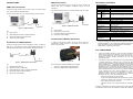
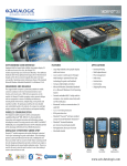
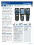
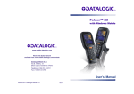
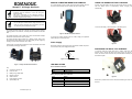
Skorpio™ X3 Single Slot Dock NOTE MOBILE COMPUTER INSERTION/ REMOVAL USING THE SPARE BATTERY CHARGER For correct insertion into the cradle, insert the mobile computer from the top of the cradle and push it down until the clip of the cradle clicks. Correctly insert the battery pack into the slot: simply press it into the slot until the battery latch is automatically closed; charging starts automatically. Read this manual carefully before performing any type of connection from the terminal to a host PC using the Single Slot Dock. The user is responsible for any damages caused by incorrect use of the equipment or by inobservance of the indication supplied in this manual. Do not attempt to disassemble the Single Slot Dock, as it does not contain parts that can be repaired by the user. Any tampering will invalidate the warranty. Figure 4 To remove the battery, release the latch on the battery pack. NOTE The Single Slot Dock paired with a Skorpio X3 mobile computer builds a reading system for the collection, decoding and transmission of barcoded data. The Single Slot Dock is both a USB and a serial communication adapter between the terminal and the host computer. The Single Slot Dock also functions as a battery charger, both for the terminal and the spare battery pack. The spare battery can be charged by inserting it into the slot at the back of the cradle. Power supply is required for the Skorpio X3 to be connected to the cradle and for battery recharging operations. Figure 2 - Mobile Computer Insertion To remove the mobile computer from the cradle, simply pull it upwards while holding the cradle firmly down. Power Supply Figure 5 Each dock requires a power supply to be connected to mobile computers. We recommend the power supply 94ACC1381. - FASTENING THE DOCK TO A SURFACE To securely fasten the Single Slot Dock to tables, desks and other surfaces, and to prevent the dock from moving when you remove the device, use the four velcro dual lock feet provided with the matching duallock adhesive pads. A G + B Figure 3 - Power Supply Polarity C E D Figure 1 –Single Slot Dock General View F LED INDICATORS Power LED Status Indicator Key: A) Contacts for Skorpio X3 Color Status B) Power on LED Green Cradle powered C) Battery charge status LED D) RS232 connector E) USB connector Color Status F) Power supply connector Off Battery absent G) Spare battery slot Red Battery charge in progress Green Charge completed Red Blinking Error 822001251 (Rev. A) Battery Charging LED Status Indicators Figure 6 Remove the protective feet from the dock before attaching the velcro dual lock feet. CONNECTIONS RS232 Connection TECHNICAL FEATURES USB Client Connection Connect the Single Slot Dock to the host by means of a standard null modem cable such as Datalogic 94A051020 CAB-427 for 9-pin connections. Connect the Single Slot Dock to the host by means of a Micro-B USB cord, such as Datalogic 94A051968 cable. Once the host has been turned on, insert the Skorpio X3 into the cradle. Electrical Features Power supply * 5 VDC ± 5% @ 3A Consumption Max 3 A with mobile computer inserted Spare slot charge time Skorpio X3 Std 1h 30 Battery 6h 30 (with mobile computer inserted) Skorpio X3 5h (when mobile computer is not inserted) High Cap Battery Communication Features Interface RS232, USB 1.1 version Baud Rate RS232 = 9600 - 115200 Physical Features Dimensions 110 x 140 x 72 mm 4,3 x 5,5 x 2,8 in Weight (without 185 g / 6,5 oz connection cables) Indicators Green power-on LED Bicolored battery charge status LED Environmental Features Working temperature** -10° to +50°C / 14° to 122°F ** Storage temperature -20° to +70°C / -4° to 158°F Humidity 95% without condensation Electrostatic discharge 4 KV contact / 8 KV air EN 61000-4-2 A Once the host has been turned on, insert the Skorpio X3 into the cradle. C A C B B D D Figure 9 – RS232 Connection Figure 7 - USB Connection Key: Key: A) Host computer B) 94A051020 9-pin serial cable A) Host computer C) 94A150031 Skorpio X3 Single Slot Dock B) 94A051968 Micro-B to Std-A USB straight cable D) 94ACC1381 Power Adapter C) 94A150031 Skorpio X3 Single Slot Dock D) 94ACC1381 Power Adapter Communication Module Extensions Connection to USB peripherals Connect the Single Slot Dock to the peripheral by means of a Micro-A USB cord, or use a Micro-A to Std-A receptacle USB adapter such as Datalogic 94A051969 (together with a standard USB cable if needed). To install a communication module, remove the label covering the communication module connector on the bottom of the cradle, as shown in the figure below: B C E Figure 10 Figure 8 - USB Peripheral Connection The communication modules available are the following: Key: A) USB Peripheral (memory) B) Standard A to Micro A USB Cable C) 94A051969 Micro-A to Std-A receptacle USB adapter D) 94A150031 Skorpio X3 Single Slot Dock E) 94ACC1381 Power Adapter Use only DL approved power adapters. ** Skorpio X3 (including spare battery) should be charged at an ambient temperature between 0 - 35º C to achieve the maximum charging rate. Never charge the main device or spare batteries in a closed space (cabinet) where excessive heat can build up. FCC COMPLIANCE D A * 94ACC1371 Single Slot Dock Ethernet Module 94ACC1372 Single Slot Dock Modem Module. This device complies with part 15 of the FCC Rules. Operation is subject to the following two conditions: (1) This device may not cause harmful interference, and (2) this device must accept any interference received, including interference that may cause undesired operation. This device has been tested and found to comply with the limits for a Class B digital device, pursuant to Part 15 of the FCC Rules. These limits are designed to provide reasonable protection against harmful interference in a residential installation. This equipment generates, uses and can radiated radio frequency energy and, if not installed and used in accordance with the instructions, may cause harmful interference to radio communications. However, there is no guarantee that interference will not occur in a particular installation If this equipment does cause harmful interference to radio or television reception, which can be determined by turning the equipment off and on, the user is encouraged to try to correct the interference by one or more of the following measures: - Reorient or relocate the receiving antenna. - Consult the dealer or an experienced radio/TV technician for help. Increase the separation between the equipment and receiver. Connect the equipment into an outlet on a circuit different from that to which the receiver is connected. Changes or modifications not expressly approved by the party responsible for compliance could void the user‘s authority to operate the equipment.