1
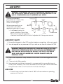
CUT OFF TOOL
MODEL: CAT113
Part No: 3120135
ASSEMBLY & INSTRUCTION
MANUAL
LS0309
INTRODUCTION
Thank you for purchasing this CLARKE product
Before attempting to use the product, it is essential that you read this manual
thoroughly and carefully follow all instructions given. In doing so you will
ensure the safety of yourself and that of others around you, and you can also
look forward to the product giving you long and satisfactory service.
GUARANTEE
This CLARKE product is guaranteed against faulty manufacture for a period of
12 months from the date of purchase. Please keep your receipt as proof of
purchase.
This guarantee is invalid if the product is found to have been abused or
tampered with in any way, or not used for the purpose for which it was
intended.
Faulty goods should be returned to their place of purchase, no product can
be returned to us without prior permission.
This guarantee does not effect your statutory rights.
ENVIRONMENTAL PROTECTION
Do not dispose of this product with general household waste. All tools,
accessories and packaging should be sorted, taken to a recycling
centre and disposed of appropriately.
PARTS & SERVICE
For parts & Servicing, please contact your nearest dealer, or
CLARKE International, on one of the following numbers.
PARTS & SERVICE TEL: 020 8988 7400
PARTS & SERVICE FAX: 020 8558 3622
or e-mail as follows:
PARTS: [email protected]
SERVICE: [email protected]
2
SAFETY PRECAUTIONS
WORK ENVIRONMENT
• Keep the work area clean and tidy.
• Dress appropriately - Do not wear loose clothing or jewellery.
• Tie long hair out of the way.
• Do not operate the cut off tool where there are flammable liquids or gases.
• Keep the air supply hose away from heat, oil and sharp edges.
• Do not fit the cut off tool to any stand or clamping device.
USE
• Stay alert and use common sense - Do not operate the cut off tool when
you are tired or under the influence of alcohol, drugs or medication.
• Always wear eye protectors when using the cut off tool - Eye protectors
must provide protection from flying particles from the front and the side.
• Always wear ear protectors when using the cut off tool.
• Do not overreach - Keep proper footing and balance at all times.
• Never use any type of bottled gas as a source of power for the cut off tool.
• Do not connect the air supply hose with your finger on the trigger.
• Do not exceed the maximum recommended pressure for the cut off tool:
90 psi / 6.2 bar.
• Check hoses for leaks or worn condition before use, and ensure that all
connections are secure.
• Do not use the cut off tool for any other purpose than described in this
book.
• Do not carry out any alterations or modifications to the cut off tool.
• Never use the cut off tool if it is defective or operating abnormally.
• The cut off tool should be serviced at regular intervals by qualified service
personnel.
• Avoid damaging the cut off tool for example by applying excessive force
of any kind.
• Alway keep the cut off tool in good condition.
3
SAFETY PRECAUTIONS
• Always disconnect from the air supply when:
a) Performing any maintenance
b) The cut off tool is not in use.
c) The cut off tool will be left unattended.
d) Moving to another work area.
e) Passing the cut off tool to another person.
• Quick change couplings should not be located at the tool. They add
weight and could fail due to vibration.
• DO NOT force or misuse the tool. It will do a better and safer job at the rate
for which it was designed.
• DO NOT remove any labels. Damaged labels should be replaced.
• This tool vibrates with use. Vibration may be harmful to your hands or arms.
Stop using the tool if discomfort, a tingling feeling or pain occurs. Seek
medical advice before resuming use.
TRANSPORTATION
• Never carry the cut off tool by the air supply hose.
• Never carry the cut off tool with your finger on the trigger.
STORAGE
• When not in use the cut off tool must be disconnected from the air supply
and stored in a dry place out of the reach of children (preferably in a
locked cabinet).
• Avoid storing the cut off tool in environments where the temperature is
below 0oC.
4
AIR SUPPLY
WARNING: COMPRESSED AIR CAN BE DANGEROUS. ENSURE THAT YOU
ARE THOROUGHLY FAMILIAR WITH ALL PRECAUTIONS RELATING TO THE
USE OF COMPRESSORS AND COMPRESSED AIR SUPPLY.
The recommended
procedure to connect this
tool to an air supply, is
shown on the right.
We recommend that an
automatic in-line filterregulator-lubricator is used.
• It will keep the tool in
good condition. The in-line
lubricator should be regularly
checked and filled with air tool oil adjusted to 2 drops per minute.
AIR SUPPLY SAFETY
1. Ensure the trigger is in the OFF position before connecting to the air supply.
2. You will require an air pressure of 90 psi, with an air flow of at least 4 CFM.
WARNING! ENSURE THE AIR SUPPLY IS CLEAN AND DOES NOT EXCEED
90PSI WHILE OPERATING THE TOOL. TOO HIGH AN AIR PRESSURE AND
UNCLEAN AIR WILL SHORTEN THE PRODUCT LIFE DUE TO EXCESSIVE
WEAR, AND MAY BE DANGEROUS CAUSING DAMAGE AND/OR
PERSONAL INJURY.
3. Drain the compressor daily. Water in the air line could damage the cut off
tool.
4. Clean air inlet filter weekly.
5. Line pressure should be increased to compensate for unusually long air
hoses (over 8 metres). The hose diameter should be 3/8" Internal Diameter.
The pressure at the cut off tool should not be over 90 psi.
AIR HOSE
• The air hose must be rated at least 150% of the maximum operating
pressure of the tool.
5
BEFORE USE
If an automatic in-line filter-regulator-lubricator is not used, the following
procedure should be carried out before use and after every two to three
hours of use.
1. Drain water from air tank, air line
and compressor.
2. Remove the plug from the rear
of the cut off tool.
Gauze Filter
(located here)
3. Check and clean the air inlet
gauze filter.
4. Pour 2-3 drops of Clarke air line
oil (approx. 3 cc), into the air
inlet. This should be carried out
regardless of whether or not an air line lubricator is used.
5. Connect tool to air supply, turn ON the air supply, and check for air leaks.
If any are apparent, rectify before proceeding.
ASSEMBLY
NOTE: Ensure the airline is turned off.
1. Screw in the adaptor supplied.
2. Connect a suitable air hose to
the cut -off tool using a ¼” hose
adapter, (A whip hose with
quick fit coupling is available
from your CLARKE dealer). Then
connect the other end to the
airline.
Your cut-off tool is now ready for use.
IMPORTANT
•
•
•
•
•
•
NEVER use cracked or chipped cutting discs.
NEVER use non-reinforced cutting discs.
NEVER use the cut off tool without disc guard in place.
NEVER use the side of the cutting disc for grinding.
ONLY use for cutting operations.
ALWAYS ensure the cutting disc has stopped before putting it down.
6
OPERATING INSTRUCTIONS
WARNING: ENSURE YOU READ, UNDERSTAND AND APPLY SAFETY
INSTRUCTIONS BEFORE USE.
1. Push safety lever (mounted on
the throttle lever) forward and
depress throttle lever.
•
Allow tool to run up to full
speed for a couple of
seconds before offering disc
to work piece.
2. Apply a steady, even pressure.
Do not force. Too much pressure
can cause disc to break and
may even cause injury.
NOTE: DO NOT allow tool to free run for an extended period of time as
this will shorten its life.
CHANGING THE CUTTING DISC
WARNING: ENSURE AIR IS TURNED OFF AND TOOL IS DISCONNECTED
FROM THE AIR SUPPLY BEFORE REPLACING DISC.
1. Ensure the disc being fitted has a speed rating greater than 18,000 RPM.
2. Install disc using spanner and
hex key supplied. Ensure that the
spacer is in place.
IMPORTANT: The use of parts other
than CLARKE replacement parts
may result in safety hazards,
decreased tool performance and
may invalidate your warranty.
Replacement cutting discs are available from your Clarke dealer.
Part number 3110731
7
MAINTENANCE
WARNING: DISCONNECT TOOL FROM AIR SUPPLY BEFORE CHANGING
ACCESSORIES, SERVICING OR PERFORMING MAINTENANCE. REPLACE
OR REPAIR DAMAGED PARTS. USE GENUINE CLARKE PARTS ONLY. NONAUTHORISED PARTS MAY BE DANGEROUS
1. Lubricate the air tool daily by placing a few drops of air tool oil into the air
inlet.
TROUBLESHOOTING.
Loss of power or erratic action may be due to the following:
a. Excessive usage on the air
line.
b. Moisture or restriction in the air
pipe.
Gauze Filter
(located here)
c. Incorrect size or type of hose
connectors.
d. Grit or gum deposits in the
tool may also reduce
performance.
e. Check and clean the gauze
filter (located in the air inlet).
If the tool runs erratically or becomes inefficient, and the air supply is sound,
take the tool to your CLARKE dealer.
STORAGE
If the tool is to be stored, or is idle for longer than 24 hours, run a few drops of
Clarke air line oil into the air inlet, and run the tool for 5 seconds in order to
lubricate the internal parts.
1. When not in use, disconnect from air supply, clean tool and store in a safe,
dry place.
8
TECHNICAL SPECIFICATION
Please note that the details and specifications contained herein, are correct
at the time of going to print. However, CLARKE International reserve the right
to change specifications at any time without prior notice.
Cutting disc diameter
3" (76mm)
No load speed
18000rpm
Air consumption
4 cfm
Operating pressure
90 psi (6.2 bar)
Weight
0.8 kg
Air inlet size
1/4" BSP
A weighted sound pressure level
96.9 dB(A)
Sound power level
107.9 dB(A)
Vibration in the handle
2.0m/s2
Dimensions (L x W x H)
183 x 83 x 80 mm
ACCESSORIES
A wide range of accessories are available, including Filter/Regulators,
Lubricators, High Pressure Hoses (5 to 100 Metres), etc.
Contact your CLARKE dealer for further information, or CLARKE International
Sales Department on 01992 565 333.
9
PARTS DIAGRAM + LIST
No
D e s c r ip t io n
Part No
No
Description
Part No
1
Ho us i ng
RONCAT11301
18 Bearing
RONCAT11318
2
Va lve Ste m S e a t
RONCAT11302
19 Back Plate
RONCAT11319
3
Tri g g e r
RONCAT11303
20 Steel Ball
RONCAT11320
4
Tri g g e r P i n
RONCAT11304
21 Rotor
RONCAT11321
5
Sp ri ng
RONCAT11305
22 Rotor Blade
RONCAT11322
6
Pin
RONCAT11306
23 Cylinder
RONCAT11323
7
Tri g g e r P i n
RONCAT11307
24 Bushing
RONCAT11324
8
O Ri ng
RONCAT11308
25 Washer
RONCAT11325
9
O Ri ng
RONCAT11309
26 Front Plate
RONCAT11326
10 Va lve Ste m
RONCAT11310
27 Bolt
RONCAT11327
11 Va lve Sp ri ng
RONCAT11311
28 Bearing
RONCAT11328
12 A i r Re g ula to r
RONCAT11312
29 Retainer Seat
RONCAT11329
13 O Ri ng
RONCAT11313
30 Retainer Ring
RONCAT11330
14 O Ri ng
RONCAT11314
31 Shielding Casing
RONCAT11331
15 S c r e w C a p
RONCAT11315
32 Front Grip
RONCAT11332
16 Muffle C o ve r
RONCAT11316
33 Washer
RONCAT11333
17 A i r Inle t P lug
RONCAT11317
34 Screw
RONCAT11334
10
DECLARATION OF CONFORMITY
11