1
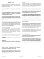
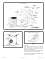
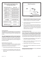
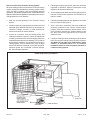
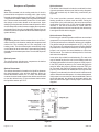
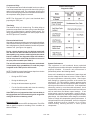
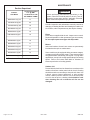
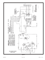
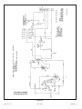
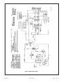
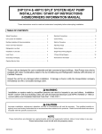
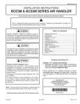
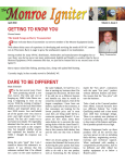
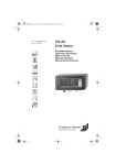
INSTALLATION AND MAINTENANCE INSTRUCTIONS
RPHP/RHP and RPCE/RCE Series
Self-Contained Heat Pump and Air Conditioner
Save these instructions for future reference
WARNING
Improper installation, adjustment, alteration, service, or maintenance can cause injury or property damage.
Refer to this manual. For assistance or additional information, consult a qualified installer or service
agency.
TABLE OF CONTENTS
WARNING
INSTALLATION ....................................................... 2
Installation and servicing of air conditioning equipment
can be hazardous due to internal refrigerant pressure
and live electrical components. Only trained and
qualified service personnel should install or service this
equipment. Installation and service performed by
unqualified persons can result in property damage,
personal injury, or death.
OPERATION ........................................................... 9
MAINTENANCE .................................................... 10
WIRING DIAGRAMS ............................................. 11
WARRANTY .......................................................... 17
WARNING
Manufactured By
Allied Air Enterprises, Inc.
A Lennox International Company
215 Metropolitan Drive
West Columbia, SC 29170
If this unit is to be installed in a mobile or manufactured
home application, the ductwork must be sized to achieve
static pressures within the manufacturer’s guidelines.
All other installation guidelines must also be followed.
Failure to do so may result in equipment damage,
personal injury, and improper performance of the unit.
*506515-01*
WARNING
For your safety, do not store or use gasoline or other
flammable vapors and liquids in the vicinity of this or
any other appliance. Such actions could result in
property damage, personal injury, or death.
CAUTION
The installation of this appliance must conform to the requirements of the National Fire Protection Association; the
National Electrical Code, ANSI/NFPA No. 70 (latest edition) in the United States; the Canadian Electrical Code Part 1,
CSA 22.1 (latest edition) in Canada; and any state or provincial laws or local ordinances. Local authorities having
jurisdiction should be consulted before installation is made. Such applicable regulations or requirements take precedence
over the general instructions in this manual.
506515-01
Issue 1038
Page 1 of 18
INSTALLATION
These instructions explain the recommended method of
installation of the heat pump and air conditioner units and
associated electrical wiring.
This unit is designed and approved for use as a selfcontained air-to-air outdoor heat pump and air conditioner
system.
The units are factory equipped with a transformer and blower
control for applications without auxiliary heat. Electric heat
accessory kits (AHSA-) can be ordered for field installation
of additional heat where required.
These instructions, and any instructions packaged with
mating components and/or accessories, should be carefully
read prior to beginning installation. Note particularly any
CAUTIONS or WARNINGS in these instructions and all
labels on the units.
These instructions are intended as a general guide only, for
use by qualified personnel and do not supersede any national
or local codes in any way. Compliance with all local, state,
provincial, or national codes pertaining to this type of equipment
should be determined prior to installation.
Inspection of Shipment
Upon receipt of equipment, carefully inspect it for possible
shipping damage. If damage is found, it should be noted on
the carrier’s freight bill. Take special care to examine the
unit inside the carton if the carton is damaged. File a claim
with the transportation company.
If any damages are discovered and reported to the carrier
DO NOT INSTALL THE UNIT, as claim may be denied.
Check the unit rating plate to confirm specifications are
as ordered.
Limitations
The unit should be installed in accordance with all national
and local safety codes.
Location
The unit is designed to be located outdoors with sufficient
clearance for free entrance to the air inlet and discharge air
openings. The location must also allow for adequate service
access. Figure 1 shows a typical installation.
The unit must be installed on a solid foundation that will not
settle or shift. Adequate structural support must be provided.
Maintain minimum clearances as shown in Figure 1 and
Table 1 and install the unit in level position. Isolate the base
from the building structure to avoid possible transmission of
sound or vibration into the conditioned space.
The heat pump unit foundation should be raised to a
minimum of 3" above finish grade. In areas which have
prolonged periods of temperature below freezing and
snowfall, the heat pump unit should be elevated above the
average snow line. Extra precaution should be taken to
allow free drainage of condensate from defrost cycles to
prevent ice accumulation. The unit should not be located
near walkways to prevent possible icing of surface from
defrost condensate.
Avoid placing the unit near quiet areas such as sleeping
quarters or study rooms. Normal operating sound levels
may be objectionable if the unit is placed near certain rooms.
Do not permit overhanging structures or shrubs to
obstruct condenser air discharge inlet or outlet.
For improved start-up performance, the indoor coil
should be washed with suitable detergent to remove
any residue from manufacturing processes.
Roof Curb Installation
If a roof curb is used, follow the manufacturer’s Installation
Instructions and be sure that all required clearances are
observed (see Clearances on page 3).
These units are shipped with four corner brackets in place
on the underside of the unit (see Figure 2). For heat pumps
the two rear corner brackets must be removed before
unit is installed onto roof curb assembly. For air
conditioner units remove all four corner brackets before
installing on roof curb.
Limitations of the unit and appropriate accessories must also
be observed.
The unit must not be installed with any ductwork in the
outdoor air stream. The outdoor fan is not designed to
operate against any additional static pressure.
Minimum and maximum operation conditions must be
observed to assure maximum system performance with
minimum service required. Refer to Table 1 for the
application limitations of the unit.
Page 2 of 18
Issue 1038
506515-01
Typical Field Wiring
Figure 1
Corner Brackets
Heat Pump Roof Curb Assembly
Figure 3
Remove rear corner brackets before installing on roof curb.
Leave front corner brackets on unit for support.
Figure 2
Clearances
All units require certain clearances for proper operation and
service. Refer to Table 1 on page 4 for the minimum
clearances to combustibles required for construction,
servicing, and proper unit operation.
In the U.S., units may be installed on combustible floors made
from wood or class A, B, or C roof covering material.
In Canada, units may be installed on combustible floors.
Units must be installed outdoors.
506515-01
Issue 1038
Page 3 of 18
The unit must be grounded with a separate ground conductor.
See Figure 4 for typical field wiring connection. The wiring
diagram can be found on the unit inside the access panel.
Low voltage control wiring are pigtail leads located on the
main control box and are color-coded to match the
connection called out on the wiring schematic.
Minimum Clearances
Combustibles
Service
Front of Unit
0
24”
Back of Unit
0
0”
Left Side
0
24”
Right Side
(Condenser Coil)
0
24”
Below Unit
0
0”
CAUTION
When connecting electrical power and control wiring to
the unit, waterproof-type connectors must be used so
that water or moisture cannot be drawn into the unit
during normal operation.
Table1
Units are factory wired for a 230-volt power supply. If
power supply is 208 volts, it will be necessary to change
a wire connection on the unit transformer from 240V
terminal to 208V terminal as shown on the wiring
diagram.
Rigging and Handling
Use only copper conductors.
If any of the original unit wiring is replaced, the same size
and type wire must be used.
CAUTION
Before lifting a unit, make sure that the weight is
distributed equally on the cables so that it will lift evenly.
Power Wiring
Exercise care when moving the unit. Do not remove any
packaging until the unit is near the place of installation. An
accessory lift kit can be purchased to aid in rigging. Spreaders
whose length exceeds the largest dimension across the unit
must be used across the top of the unit.
Line Voltage 208/230 Volts
Units may also be moved or lifted with a forklift while still in
the factory-supplied packaging. The lengths of the forks
of the forklift must be a minimum of 42".
If 208 volt is supplied, transformer connections must be
changed.
Compressor
Units are shipped with compressor mountings factory
adjusted and ready for operation. Do not loosen
compressor mounting bolts.
Figure 4
Electrical Wiring
All field wiring must be done in accordance with National
Electrical Code recommendations, local codes, and
applicable requirements of UL, or in accordance with
Canadian Electrical Code recommendations, local codes,
or CSA Standards. Power wiring, disconnect means, and
over-current protection are to be supplied by the installer.
Refer to the unit rating plate for maximum over-current
protection and minimum circuit ampacity, as well as operating
voltage. The power supply must be sized and protected
according to specifications supplied.
Page 4 of 18
Issue 1038
506515-01
Thermostat
The room thermostat should be located on an inside wall
where it will not be subject to drafts, sun exposure, or heat
from electrical fixtures or appliances. Follow the
manufacturer’s instructions enclosed with the thermostat for
general installation procedure. Color-coded insulated wires
(#18 AWG) should be used to connect the thermostat to the
unit. A minimum of five wires are required for proper
installation.
Typical Wiring Connections
Ductwork
Ductwork should be designed and sized according to the
methods in Manual Q of the Air Conditioning Contractors of
America (ACCA).
A closed return duct system shall be used. This shall not
preclude use of economizers or outdoor fresh air intake. It
is recommended that supply and return duct connections at
the unit be made with flexible joints.
The supply and return air duct systems should be designed
for the CFM and static requirements of the job. They should
not be sized to match the dimensions of the duct
connections on the unit.
CAUTION
When fastening ductwork to side duct flanges on unit,
insert screws through duct flanges only. Do not insert
screws through casing. Outdoor ductwork must be
insulated and waterproofed.
Filters
Filters are not supplied with the unit. Filters must always be
installed on the upstream side of the evaporator coil and
must be kept clean or replaced. Dirty filters will reduce the
airflow of the unit. Filters should be sized in accordance with
Table 2 on page 6.
This unit is equipped with an internal filter clip which is located
in the indoor coil compartment attached to the side of the
unit drain pan.
Figure 5
506515-01
Issue 1038
Page 5 of 18
Minimum Required Surface Area
for Disposable Filters
Drain Connection
Figure 6
3. Remove the heater blockoff by removing the four screws
holding it in place. Cut away the insulation covering the
opening, using the hole in the panel as a template.
4. Insert the heater into the control panel and fasten in the
same mounting holes.
5. Plug the heater wiring harness into the wire harness on
the control assembly. Field wiring of the auxiliary heater
is separate from the unit power supply. Wire the power
supply wiring for the heater to the appropriate
connections on the heater kit.
Table 2
Condensate Drain
The package unit is equipped with a 3/4" fpt coupling for
condensate line connection. Plumbing must conform to local
codes. Use a sealing compound on the male adaptor pipe
threads.
The condensate drain line must be properly trapped and
routed to a suitable drain. See Figure 6 for proper drain
arrangement. The drain line must pitch to an open drain or
pump to prevent clogging of the line. Seal around the drain
connection with suitable material to prevent air leakage into
the return air system.
Heater Kit Accessory (if used)
The unit is fully equipped for cooling operation without
auxiliary heat. A heater kit accessory may also be used. To
install the heater kit accessory (see Figure 7):
1. Disconnect the power and open the main control access.
2. Disconnect the plug separating the high voltage wire
harness. Remove the high voltage wire harness plug
and discard.
Page 6 of 18
Crankcase Heater (if used)
Some models may be equipped with insertion crankcase
heaters to prevent excessive migration of liquid refrigerant
into the compressor. The following steps should be taken
on initial start-up to prevent possible compressor damage.
The procedure must be followed at initial start-up as well as
any time power has been interrupted for 12 hours or longer.
1. Insure that the room thermostat is in OFF position to
prevent the compressor from starting.
2. Apply the main power supply to the outdoor unit. This
will energize the crankcase heater.
3. Maintain power to the unit for a minimum of 8 hours.
4. After reaching minimum elapsed time, the unit can be
safely started.
Except as required for safety while servicing, do not open
the system disconnect switch.
Issue 1038
506515-01
Removal of Unit from Common Venting System
When an existing furnace is removed from a common venting
system serving other appliances, the venting system is likely
to be too large to properly vent the remaining attached
appliances. The following test should be conducted with each
appliance while the other appliances connected to the common
venting system are not in operation.
4. Following the lighting instructions, place the unit being
inspected in operation. Adjust the thermostat so the
appliance will operate continuously.
1. Seal any unused openings in the common venting
system.
6. Follow the preceding steps for each appliance connected
to the common venting system.
2. Visually inspect the venting system for proper size and
horizontal pitch and determine there is no blockage or
restriction, leakage, corrosion, or other deficiencies
which could cause an unsafe condition.
7. After it has been determined that each appliance
remaining connected to the common venting system
properly vents when tested as outlined above, return
doors, windows, exhaust fans, fireplace dampers, and
any other fuel burning appliance to their previous
condition of use.
3. Insofar as is practical, close all building doors and
windows between the space in which the appliances
remaining connected to the common venting system are
located and other spaces in the building. Turn on clothes
dryers and any appliance not connected to the common
venting system. Turn on exhaust fans, such as range
hoods and bathroom exhausts, so they will operate at
maximum speed. Do not operate a summer exhaust
fan. Close fireplace dampers.
5. Test for spillage at the draft control relief opening after 5
minutes of main burner operation. Use the flame of a
match or candle.
8. If improper venting is observed during any of the above
tests, the common venting system must be corrected.
See National Fuel Gas Code, ANSI Z223.1 (latest
edition) or CAN/CGA B149.1 & .2 Canadian
Installation Codes to correct improper operation of
common venting system.
Heater Kit Accessory Installation
Figure 7
506515-01
Issue 1038
Page 7 of 18
Sequence of Operation
Cooling
When the thermostat is in the cooling mode, the O circuit is
powered which energizes the reversing valve. Upon cooling
demand, the thermostat closes circuit R and Y. Closing R and
Y closes the unit contactor, starting the compressor and outdoor
fan. The thermostat automatically closes R to G circuit which
also brings on the indoor blower at the same time. Upon
satisfying cooling demand, the thermostat will open the above
circuits and open the main contactor, stopping the compressor
and outdoor fan. If the unit is equipped with a delay timer, the
blower will continue to operate for 90 seconds which improves
system efficiency.
Heating
Upon heating demand, the thermostat closes circuit R to Y,
which closes the unit contactor, starting the compressor and
outdoor fan. The reversing valve is not energized in the
heating mode. The thermostat again automatically brings
on the indoor fan at the same time. Upon satisfying heating
demand, the thermostat opens above circuits and stops unit
operation.
Defrost System
The defrost system includes two components: the defrost
thermostat and the defrost control.
Defrost Thermostat
The defrost thermostat is located on the liquid line between
the check/expansion valve and the distributor. When the
defrost thermostat senses 42°F or cooler, the thermostat
contacts close and send a signal to the defrost control board
to start the defrost timing. It also terminates defrost when
the liquid line warms up to 70°F.
Defrost Control
The defrost control board includes the combined functions
of time/temperature defrost control, defrost relay, diagnostic
LEDs and terminal strip for field wiring connections (see
Figure 8).
The control provides automatic switching from normal
heating operation to defrost mode and back. During the
compressor cycle (call for defrost), the control accumulates
compressor run time at 30, 60, 90 minute field-adjustable
intervals. If the defrost thermostat is closed when the
selected compressor run time interval ends, the defrost relay
is energized and the defrost begins.
Defrost Control Timing Pins
Each timing pin selection provides a different accumulated
compressor run time period during one thermostat run cycle.
This time period must occur before a defrost cycle is initiated.
The defrost interval can be adjusted to 30 (T1), 60 (T2), or
90 (T3) minutes. The defrost timing jumper is factory installed
to provide a 60-minute defrost interval. If the timing selector
jumper is not in place, the control defaults to a 90-minute
defrost interval. The maximum defrost period is 14 minutes
and cannot be adjusted.
A test option is provided for troubleshooting. The test mode
may be started any time the unit is in the heating mode and
the defrost thermostat is closed or jumpered. If the jumper is
in the TEST position at power up, the control will ignore the
test pins. When the jumper is placed across the TEST pins
for 2 seconds, the control will enter the defrost mode. If the
jumper is removed before an additional 5-second period has
elapsed (7 seconds total), the unit will remain in defrost mode
until the defrost thermostat opens or 14 minutes have passed.
If the jumper is not removed until after the additional 5-second
period has elapsed, the defrost will terminate and the test
option will not function again until the jumper is removed and
reapplied.
Defrost Control Board
Figure 8
Page 8 of 18
Issue 1038
506515-01
Compressor Delay
The defrost board has a field-selectable function to reduce
occasional sounds that may occur while the unit is cycling in
and out of the defrost mode. The compressor will be cycled
off for 30 seconds going in and out of the defrost mode when
the compressor delay jumper is removed.
Defrost Control Board
Diagnostic LEDs
NOTE: The 30-second “off” cycle is not functional when
jumpering the TEST pins.
Time Delay
The timed-off delay is 5 minutes long. The delay helps to
protect the compressor from short cycling in case the power
to the unit is interrupted or a pressure switch opens. The
delay is bypassed by placing the timer select jumper across
the TEST pins for 0.5 seconds.
Pressure Switch Circuit
High and low pressure switches are connected to the defrost
control board on heat pump models. Air conditioning models
have a high pressure switch installed in line with compressor
contactor coil. (see Figure 8 on page 8).
During a single demand cycle, the defrost control will
lock out the unit after the fifth time that the circuit is
interrupted by any pressure switch wired to the control
board. In addition, the diagnostic LEDs will indicate a
locked-out pressure switch after the fifth occurrence of
an open pressure switch (see Table 3).
The unit will remain locked out until power to the board
is interrupted, then re-established, or until the jumper
is applied to the TEST pins for 0.5 seconds.
NOTE: The defrost control board ignores input from the low
pressure switch terminals as follows:
•
During the TEST mode
•
During the defrost cycle
•
During the 90-second start-up period
•
For the first 90 seconds each time the reversing
valve switches heat/cool modes
If the TEST pins are jumpered and the 5-minute delay is
being bypassed, the LO PS terminal signal is not ignored
during the 90-second start-up period.
Diagnostic LEDs
The defrost board uses two LEDs for diagnostics. The LEDs
flash a specific sequence according to the condition as
shown in Table 3.
506515-01
Table 3
System Performance
This equipment is a self contained, factory optimized
refrigerant system, and should require no adjustments when
properly installed. If however unit performance is
quiestioned, perform the following checks.
Insure unit is installed per manufacturer’s instructions and
that line voltage and air flows are correct. Refer to Table 3
for proper superheat or subcooling values. Check super
heat settings by measuring pressure at the suction line
service port. For TXV systems, measure pressure at the
liquid service port. Take line temperature within 2 inches of
service port connection to its main tube. If unit superheat/
subcooling varies by more than table allowance, check
internal seals, service panels and duct work for air leaks, as
well as restrictions and blower speed settings. If unit
performance remains questionable, remove charge,
evacuate to 500 Microns, and werigh in refrigerant to name
plate charge. It is critical that the exact charge is re-installed.
Failure to comply will compromise system performance. If
uinit performance is still questionable, check for refrigerant
related problems such as, blocked coil or circuits,
malfunctioning metering devices or other system
components.
Issue 1038
Page 9 of 18
MAINTENANCE
Suction Superheat
WARNING
Suction Superheat
+/- 3° @ ARI
Conditions 82° OD
80° IDDB/67° IDWB
Outdoor
Unit Model
RPHP/RHP13(*) 24
17
RPHP/RHP13(*)30
20
RPHP/RHP13(*)36
16
RPHP/RHP13(*)42
17
RPHP/RHP13(*)48
19
RPHP/RHP13(*)60
19
RPCE/RCE13(*)24
18
RPCE/RCE13(*)30
17
RPCE/RCE13(*)36
17
RPCE/RCE13(*)42
16
RPCE/RCE13(*)48
15
RPCE/RCE13(*)60
13
* These letters will vary according to unit series.
Before performing maintenance operations on the
system, shut off all electrical power to the unit. Turn off
accessory heater power switch if applicable. Electrical
shock could cause personal injury or death.
Periodic inspection and maintenance normally consists of
changing or cleaning the filters and cleaning the outdoor coil.
On occasion, other components may also require cleaning.
Filters
Filters are not supplied with the unit. Inspect once a month.
Replace disposable or clean permanent type as necessary.
Do not replace permanent type with disposable.
Motors
Indoor and outdoor fan and vent motors are permanently
lubricated and require no maintenance.
Some models may be equipped with a permanent magnet,
constant torque indoor blower motor. These motors remain
energized and are controlled by 24V signals. For high static
applications, use tap 3 for cooling speed and tap 5 for heating
speed. Refer to the heater install label for limitations to
blower tap selection on heating speeds.
Table 4
Outdoor Coil
Dirt and debris should not be allowed to accumulate on the
outdoor coil surface or other parts in the air circuit. Cleaning
should be as often as necessary to keep the coil clean. Use
a brush, vacuum cleaner attachment, or other suitable
means. If water is used to clean the coil, be sure the power
to unit is shut off prior to cleaning. Care should be used
when cleaning the coil so that the coil fins are not
damaged.
Page 10 of 18
Issue 1038
506515-01
230V SINGLE PHASE
HEAT PUMP
Figure 9
506515-01
Issue 1038
Page 11 of 18
230V SINGLE PHASE
ELECTRIC/ELECTRIC
Figure 10
Page 12 of 18
Issue 1038
506515-01
230V 3 PHASE HEAT PUMP
Figure 11
506515-01
Issue 1038
Page 13 of 18
230V 3 PHASE ELECTRIC/ELECTRIC
Figure 12
Page 14 of 18
Issue 1038
506515-01
460V 3 PHASE HEAT PUMP
Figure 13
506515-01
Issue 1038
Page 15 of 18
460V 3 PHASE ELECTRIC/ELECTRIC
Figure 14
Page 16 of 18
Issue 1038
506515-01
ALLIED AIR ENTERPRISES
EQUIPMENT LIMITED WARRANTY
APPLIES IN U.S.A. AND CANADA ONLY
FAILURE TO MAINTAIN YOUR EQUIPMENT WILL VOID THIS WARRANTY
COVERED EQUIPMENT
The following Allied Air Enterprises heating and cooling equipment is covered by the Limited Warranty,
Condensing Units: 2SCU13, 4SCU13, 4SCU14, 4SCU16, 4SCU18, 2AC13, 2AC14, 4AC13, 4AC14
Heat Pumps: 2SHP13, 4SHP13, 2SHP14, 4SHP14, 4SHP16, 4SHP18, 2HP13, 2HP14, 4HP13, 4HP14
Gas Furnaces: G1N80, G1D80, G2D80, G1D91, G1D93, G2D93, G2D95, FPBB, CG80, CG90, CG92, CG93, CG95
Oil Furnaces: LBR80, LBF80, LHF80, LUF80, LHR80, RLUF, RLBF, RLBR, RLBU, RLHF, RLHR
Electric Furnaces: EFC, EFV
Evaporator Coils: EC, EU, EH, EM
Air handlers: BCS2, RBCS2
Package Equipment: 2PCE13, 4PCE13, 4PCE15, 2PGE13, 4PGE13, 4PGE15, 2PHP13, 4PHP13, 4PHP15, 2SG13, 2SH13, 2SA13, RGE13, RPGE13, RHP13, RCE13, RPHP13, RPCE13
PARTS and COMPRESSOR COVERAGE
The covered equipment, parts and compressor are warranted by Allied Air for a period of five (5) years from the date of the original installation, when installed in a residential application (which includes
homes, duplexes, apartments and condominiums). For non-residential applications, the covered equipment and parts are warranted for a period of one (1) year and compressor is warranted for five (5)
years from the date of the original installation. If, during this period, a covered component fails because of a manufacturing defect, Allied Air will provide a free replacement part to the owner through a
licensed service contractor utilizing an Allied Air distributor. The purchaser must pay shipping charges and all other costs of warranty service. Allied Air will not pay labor involved in diagnostic calls or
in removing, repairing, servicing or replacing parts. Such cost may be covered by a separate warranty provided by the installer.
HEAT EXCHANGER EXTENDED COVERAGE
All covered heat exchangers are warranted by Allied Air for a period of twenty (20) years from the date of original installation, when installed in a residential application. Heat exchangers in all nonresidential applications are warranted for a period of ten (10) years.
Heat Exchanger Availability: If a replacement heat exchanger is no longer available for a unit covered by this Limited Warranty, Allied Air will allow a credit toward the purchase of an equivalent Allied
Air furnace (at the current suggested distributor’s cost).
NOTE: If the date of original installation cannot be verified, the warranty period will be deemed to begin ninety (90) days after the date of manufacture.
EXCLUDED COMPONENTS
The following components are expressly not covered by this Limited Warranty: cabinets, cabinet pieces, air filters, driers, refrigerant, refrigerant line sets, belts, wiring, fuses, oil nozzles, unit accessories
and any parts not affecting unit operation
CARE OF EQUIPMENT
All new Allied Air units must be properly installed, operated and maintained in accordance with the unit installation, operation and maintenance instructions provided with each Allied Air unit. Failure to
maintain the equipment per Allied Air instructions will void this Limited Warranty.
WARRANTY PROCEDURE
When service or warranty parts are required:
1.
Call a local licensed service dealer or contractor.
2.
If the installing dealer is unable to provide warranty service, check online at www.alliedair.com.
3.
Be prepared to furnish the following information:
a. complete model and serial number;
b. proof of required periodic maintenance, installation date and location; and
c. an accurate description of the problem.
WARRANTY LIMITATIONS
1.
This Limited Warranty is void if the covered equipment is removed from the original installation site.
2.
This Limited Warranty does not cover damage or defect resulting from:
a. flood, wind, fire, lightning, mold, or installation and operation in a corrosive atmosphere, or otherwise in contact with corrosive materials (chorine, fluorine, salt, recycled waste water, urine,
fertilizers, or other damaging substances or chemicals); accident, or neglect or unreasonable use or operation of the equipment including operation of electrical equipment at voltages other
than the range specified on the unit nameplate (includes damages caused by brownouts);
b. modification, change or alteration of the equipment, except as directed in writing by Allied Air;
c. operation with system components (indoor unit, outdoor unit and refrigerant control devices) which are not an ARI match or meet the specifications recommended by Allied Air;
d. operation of furnaces with return air temperatures of less than 60ºF (16ºC) or operation of a furnace field installed downstream from a cooling coil; and
e. use of contaminated refrigerant or refrigerant not compatible with the unit.
The installation of replacement parts under the terms of this Limited Warranty does not extend the original warranty period.
Allied Air makes no express warranties other than the Limited Warranty specified above. All implied warranties, including the implied warranties of merchantability and fitness for a
particular purpose, are excluded to the extent legally permissible. Should such exclusion or limitation of this Limited Warranty be unenforceable, such implied warranties are in any event
limited to a period of one (1) year. Liability for incidental and consequential damages is excluded. Some states do not allow limitation of incidental damages, so these limitations or
exclusions may not apply to you. Allied Air will not pay electricity or fuel costs, or increases in electricity or fuel costs, for any reason whatsoever, including additional or unusual use of
supplemental electric heat. This Limited Warranty does not cover lodging expenses or labor charges.
Allied Air shall not be liable for any default or delay in performance under this Limited Warranty caused by any contingency beyond its control.
This Limited Warranty gives you specific legal rights, and you may also have other rights which vary from state to state.
NOTE TO CUSTOMER:
Please complete information below and retain this warranty for your records and future reference.
Outside Unit Model Number: ____________________________________________________ Serial Number: _______________________________________ Installed Date: __________________
Furnace / Air Handler: _________________________________________________________ Serial Number: _______________________________________ Installed Date: __________________
Indoor Coil Model Number: _____________________________________________________ Serial Number: _______________________________________ Installed Dare: __________________
Installing Company Name: ___________________________________________________________________________________ Phone: _______________________________________________
Installing Company Address: _____________________________________________________________ State/Province: _______________________________ Zip/Postal Code: _______________
215 Metropolitan Drive - West Columbia - SC - 29170
© 2008 Allied Air Enterprises
Litho U.S.A.
FORM W-2008-2 (9/25/2009)
506515-01
Issue 1038
Page 17 of 18
5-YEAR LIMITED EXTENDED PARTS WARRANTY
Allied Air Enterprises Inc. (“Allied Air”) provides its air conditioning and heating products with a Standard Limited Parts Warranty for five (5) years. This additional 5-Year Limited Extended
Parts Warranty is in addition to and is intended to supplement Allied Air’s Standard Limited Parts Warranty. As such, Allied Air provides for a total of 10-years of limited warranty coverage
(Standard Limited Parts Warranty plus additional 5-Year Limited Extended Parts Warranty).
This 5-Year Limited Extended Parts Warranty applies only to the original purchaser of the equipment and cannot be transferred. If during the coverage period, a covered part fails
because of a defect in materials or workmanship under normal use and maintenance, Allied Air will provide a free replacement part to the purchaser through a licensed service contractor
utilizing an authorized Allied Air distributor. The purchaser must pay shipping costs and all other costs of warranty service. Allied Air will not pay labor involved in diagnostic calls or in
removing, repairing, servicing or replacing parts.
EXTENDED COVERAGE PARTS/COMPRESSORS
Covered equipment and parts are warranted by Allied Air for a total of 10 YEARS (Standard Limited Parts Warranty) from installation, except as provided below
HEAT EXCHANGERS
Covered residential heating equipment’s heat exchanger is warranted by Allied Air for a LIMITED LIFETIME from date of original installation, except as provided below.
EXCLUDED COMPONENTS The following components are expressly not covered by this 5-Year Limited Extended Parts Warranty: cabinets, cabinet pieces, air filters, driers, refrigerant, refrigerant line sets, belts,
wiring, fuses, oil nozzles, unit accessories, R-22 compressors, and any parts not affecting unit operation.
REQUIREMENTS FOR EXTENDED COVERAGE1.
The unit is an Armstrong Air, Air ease, Ducane, or Concord branded unit;
2. The unit is installed in a residential application, which is an owner-occupied single-family residence. No commercial applications are allowed;
1
3. The unit is properly registered at www.alliedair.com with Allied Air within 60-days after the original date of installation or occupancy. To
register, follow the directions and complete the online warranty registration at www.alliedair.com. For customer inquiries, contact Allied Air at
1-800-448-5872.
4. The unit is part of a complete ARI matched system and installed by a state certified or licensed contractor in accordance with the unit installation, operation,
and maintenance instructions provided with the unit.
5. Coils and air handlers are covered only when they are branded Armstrong, AirEase, Ducane, Concord or ADP and are purchased and newly installed as a
system along with a qualifying unit. Except for ADP-branded products, coverage of other third party coils and air handlers are specifically excluded from
this 5-Year Limited Extended Parts Warranty.
6.
Installation of the unit takes place on or after October 3, 2008.
If this 5-Year Limited Extended Warranty does not apply, then parts are warranted under the Standard Limited Parts Warranty for a period of 5 YEARS and heat exchangers for 20
YEARS. If the Standard Limited Parts Warranty periods differ from the original warranty certificate, the periods stated on the original warranty certificate apply.
This 5-Year Llimited Extended Parts Warranty does not apply to, and no warranty is offered by Allied Air, on any unit ordered over the internet. Proof of purchase may be required.
Any part replaced pursuant to this 5-Year Limited Extended Parts Warranty is warranted only for the unexpired portion of the limited extended warranty term remaining for the original part.
The installation of replacement parts under the terms of this 5-Year Limited Extended Parts Warranty does not extend the warranty period.
Steps for obtaining replacement parts under this 5-Year Limited Extended Parts Warranty:
If you suspect a defect in your equipment, please contact the installer of the unit to obtain assistance. If unsuccessful, please contact an Allied Air dealer or distributor in
your area. If unable to obtain local assistance, refer to Allied Air’s website (www.alliedair.com) or contact Allied Air at 800-448-5872.
Allied Air is specifically not responsible for:
1. Damage or repairs required as a result of flood, fire, wind, lightening strike (to the home or unit), corrosive atmosphere, contact with corrosive material (chlorine, fluorine, salt, recycled
waste water, fertilizers or other damaging substances) or other conditions beyond the control of Allied Air;
2. Use of parts, accessories, or refrigerant not compatible with the unit;
3. Modification, change or alteration of the unit, except as expressly directed in writing by Allied Air;
4. Improper use, accident, neglect or unreasonable use or operation of the unit, including operation of electrical equipment at voltages other than the range specified on the unit
nameplate;
5. Operation with system parts (indoor unit, outdoor unit and refrigerant control devices) which are not ARI matched or do not meet the specifications recommended by Allied Air;
6. Damage or repairs required as a consequence of faulty or installation or application;
7. Normal maintenance as described in the installation and operating manual, such as cleaning of coils, filter cleaning and/or replacement and lubrication; and
8. Changes in the appearance or sound of the unit that do not affect its performance.
This 5-Year Limited Extended Parts Warranty is an extension of Allied Air’s Standard Limited Parts Warranty. ANY IMPLIED WARRANTY OF MERCHANTABILITY OR FITNESS FOR
A PARTICULAR PURPOSE ON THIS PRODUCT IS LIMITED IN DURATION TO THE TERM OF THIS LIMITED EXTENDED WARRANTY. Some states and provinces do not allow
limitations on how long an implied warranty lasts, so the above limitation may not apply to you.
ALLIED AIR SHALL IN NO EVENT BE LIABLE FOR INCIDENTAL OR CONSEQUENTIAL DAMAGES, INCLUDING BUT NOT LIMITED TO EXTRA UTILITY EXPENSES OR
DAMAGES TO PROPERTY. Some states and provinces do not allow the exclusion or limitation of incidental or consequential damages, so the above limitation or exclusion may not
apply to you
The parties intend this writing as a final expression of their agreement with respect to warranties. Allied Air makes no other warranty beyond that which is expressly
contained in this writing.
Allied Air shall not be liable for any default or delay in performance under this warranty caused by any contingency beyond its control, including the unavailability of replacement parts.
This warranty gives you specific legal rights, and you may also have other rights that vary from state to state or province to province.
1
Excludes residents of states or provinces where registration requirements are prohibited, such as California and Quebec. Residents of these states or provinces may either register as noted above or
provide proof of when the unit was purchased and installed, such as an original invoice from the contractor with the Owner’s name, address, purchase date, serial and model number.
Page 18 of 18
Issue 1038
506515-01