1
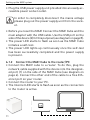
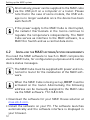
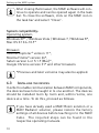
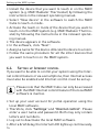
Operating manual
Cube LAN Gateway
BC-LGW-O-TW
Package
contents

Package contents
Quantity Item
1x
MAX! Cube LAN Gateway
1x
Plug-in USB power supply
1x
USB cable
1x
Network cable
1x
Mounting accessories
1x
Assembly bracket for wall mounting
3x
Brief instruction in German/English, French/
Dutch and Polish/Italian
2

Table of contents
Table of contents
1
Information about this manual.................................. 4
2
Safety instructions..................................................... 4
3Function..................................................................... 5
4
Device overview.......................................................... 8
5Mounting.................................................................... 9
6
Setting up the MAX! system..................................... 10
7
Restore factory settings........................................... 15
8
LED flashing sequences and
transmission behaviour........................................... 17
9
Maintenance and cleaning....................................... 18
10 Information about radio operation.......................... 18
1st English edition 07/2014
Documentation © 2014 eQ-3 AG, Germany
All rights reserved. Translation from the original version in German.
V1.1
3
Information about this manual
1
Information about this manual
Read this manual carefully before starting to use the device.
Keep the manual so you can refer to it at a later date if you
need to. If you hand over the device to other persons for use,
please hand over the operating manual as well.
Symbols used:
Attention!
This indicates a hazard.
Note.
This section contains important additional information.
2
Safety instructions
The device is not a toy; do not allow children to play
with it. Do not leave packaging material lying around,
as it can be dangerous in the hands of a child.
Do not open the device: it does not contain any components that need to be serviced by the user. In the
event of an error, please return the device to the service department.
The device may only be operated indoors and must be
protected from the effects of damp and dust, as well
as solar or heat radiation.
4
Function
Using the device for any purpose other than that described in this operating manual does not fall within
the scope of intended use and shall invalidate any warranty or liability. This also applies to any conversion
or modification work. The device is intended for private
use only.
3
Function
With the MAX! Heating Control system, the room temperature
in apartments, houses and other small buildings can
comfortably be controlled and regulated.
MAX! Heating Control offers three expandable solutions:
MAX! Radiator solution
Local control for single radiators via the MAX! Radiator Thermostat+.
MAX! Room solution
Central control of all radiators in one room via the
MAX! Wall Thermostat+.
MAX! House Solution
Central control of all radiators in your house via smartphone and Internet.
5
Function
The MAX! Cube as central element of the MAX! House solution offers convenient control of all MAX! devices in your
house in several ways:
•via the local MAX! software on your PC,
•via the MAX! Internet control from any PC with Internet
connection or
•via the MAX! app for iOS and Android smartphones.
Please note that the MAX! system can be controlled
via the local MAX! software, Internet control or app.
The three different interfaces can not be used at the
same time.
Additionally, the status of all MAX! devices can be checked
via the MAX! Cube at all times. The MAX! Cube links the MAX!
devices in your house and your computer network. Furthermore, the device stores any settings and configurations that
you have made.
Different settings and configurations for all MAX! devices
can be made for individual rooms. As the MAX! Cube saves
all settings and configurations, the system can be operated
even without PC or active Internet connection. The wireless
communication between MAX! components is performed
in two directions (bidirectional). This ensures that the information sent reaches the recipient and possible interferences are detected.
If you have been using the MAX! Room solution or the MAX!
Radiator solution so far, all MAX! devices can easily be integrated into to MAX! House solution. Therefore, you only have
6
Function
to restore the factory settings of your MAX! components and
teach-in the devices to the MAX! Cube. You will find further
information in the operating manual of the single devices
(available for download at max.eQ-3.com).
7
Device overview
4
Device overview
Top:1
Power: The LED indicates whether a
power supply is present and if the device is ready for operation.
Internet: The LED indicates whether a
connection to the LAN/Internet exists.
Battery: The LED indicates whether a
battery needs to be replaced on a MAX!
component.
Bottom side:
Reset button: For restoring
the factory settings
Side:
1) Network port to connect to a router.
(2) Port for for USB power supply (see
Section 6.1)
1 see sec. 8 "LED flashing sequences and transmission behaviour"
8
Mounting
5
Mounting
The MAX! Cube can be fastened to the wall or be used as
standing unit.
Use the wall bracket if you wish to mount the MAX! Cube
on a wall:
•Use a pen to mark the bore hole positions (a) on the wall.
•Use a drill to make the holes as illustrated (a).
•Use the screws and plugs supplied to fasten the bracket
to the wall.
•Once the wall bracket is in place, the MAX! Cube can be
attached to the wall bracket from above, with the opening pointing down.
9
Setting up the MAX! system
6
Setting up the MAX! system
Setting up the MAX! system involves the following steps:
•Connecting the MAX! Cube,
•MAX! Installing the software
•installing and teaching in the MAX! devices,
•setting up Internet control
6.1
Connecting the MAX! Cube
6.1.1 Connect the MAX! cube to the power supply:
The MAX! Cube draws its power supply from the plug-in main
adapter included in the scope of supply.
To avoid damaging the device, please only use the
original main adapter supplied with the device for the
power supply.
10
Setting up the MAX! system
•Plug the USB power supply unit provided into an easily accessible power socket outlet.
In order to completely disconnect the mains voltage
please plug out the power supply unit from the socket.
•Before you reset the MAX! Connect the MAX! Cube and the
main adapter with the USB cable. Use the USB port on the
side of the device (2) for this purpose (see diagram on page 8).
•The power LED starts to flash as soon as the MAX! Cube
initiates a self-test.
•The power LED lights up continuously once the self-test
has been successfully completed and the power supply
is present.
6.1.2 Connect the MAX! Cube to the router/PC
•Connect the MAX! cube to a router. To do this, plug the
network cable supplied with the device into the designated port (1) on the side of the MAX! Cube (see diagram on
page 4). Connect the other end of the cable to a free Ethernet port on your router.
•Connect the router to your PC.
•The Internet LED starts to flash as soon as the connection
to the router is active.
11
Setting up the MAX! system
Alternatively, power can be supplied to the MAX! cube
via the USB port on a computer or a router. Please
note that in the case of some models, the USB voltage is no longer available once the device has been
switched off.
If the power supply to the MAX! Cube is interrupted,
the radiator thermostats in the rooms continue to
regulate the temperature independently. The MAX!
Cube serves as interface to the MAX! software, to a
MAX! Eco Switch and as a central data store.
6.2
Installing the MAX! software/system requirements
You need the MAX! software to teach in MAX! components
via the MAX! Cube, for configuration purposes and to call up
device status messages.
The MAX! Cube must be supplied with power and connected to router for the installation of the MAX! software.
When the MAX! Cube is being set up, DHCP must be
activated on the router. Alternatively, the following
address can be manually assigned to the MAX! cube
via the MAX! software: 192.168.0.222.
•Download the software for your MAX! House solution at
max.eQ-3.com.
•Install the software on your PC. The software launches
automatically and the software interface is displayed in
your browser.
12
Setting up the MAX! system
After closing the browser, the MAX! software will continue to operate and can be opened again in the task
bar. To close the software, click on the MAX! icon in
the task bar and select "Close".
System compatibility:
Operating system: Windows XP® / Windows Vista / Windows 7 / Windows 8*, Mac OS X 10.6-10.9*
Browser: Internet Explorer® version 11*,
Mozilla Firefox® version 26*,
Safari version 6 or 5.1.9 (Mac)*,
Google Chrome version 31* and other browsers
*Previous and later versions may also be applied.
6.3
Installing the devices
In order to enable communication between MAX! components,
the devices have to be taught in to one another. The devices
should be installed room by room and, within rooms, one
device at a time. To do this, proceed as follows:
If you have already used a MAX! Room solution or a
MAX! Radiator solution, please restore the factory
settings of all devices before teaching in to the MAX!
Cube. The required steps can be found in the
respective operating manuals.
13
Setting up the MAX! system
•Install the device that you want to teach in on the MAX!
system (e.g. MAX! Radiator Thermostat) by following the
instructions in the relevant operating manual.
•Select "New device" in the software to switch the MAX!
Cube to teach-in mode.
•Activate the teach-in mode of the device that you want to
teach-in to the MAX! system (e.g. MAX! Radiator Thermostat) by following the instructions in the relevant operating manual.
•The device appears in the software.
•In the software, click "Next".
•Assign a name for the device. Allocate the device to a room.
•Follow the same procedure for all the other devices that
you want to teach in on the MAX! system.
6.4
Setting up Internet control
If you want to be able to control your system using the Internet control feature or via a smartphone, then Internet access
must also be enabled and Internet control must be set up.
Please note that the MAX! Cube can only be accessed
with the MAX! Internet control feature if the local MAX!
software is inactive.
•Set up your user account for portal operation using the
local MAX! software.
•Therefore, click "Settings" and "Internet control". Please
enter a user name and password. Both may only contain
letters and numbers.
•Log out to deactivate the local MAX! software.
•After a brief delay, the Internet LED lights up continuously.
14
Restore factory settings
The connection to the MAX! Portal is active and the MAX!
Cube is now ready for operation.
You can use the MAX! You now have a flexible means of controlling and configuring your MAX! system and can access
it from home as well as on the move via Internet access.
7
Restore factory settings
The factory settings of the MAX! Cube can be restored
anytime.
When the factory settings are restored, all information about taught-in devices and all settings made are
lost and cannot be retrieved.
•Disconnect the MAX! Cube from the power supply and
wait for 1 minute.
•Press and hold down the reset button and at the same
time reconnect the power supply.
15
Restore factory settings
IP-Adr. 192.168.0.222
Reset
•The Power LED lights up and then starts to flash.
•The Power LED lights up permanently again. The factory
settings of the device are now restored.
16
LED flashing sequences and transmission behaviour
8
LED
flashing sequences and transmission
behaviour
LED
Power
LED
Internet
LED
State
LED off
LED flashing
Meaning
Power supply interrupted
MAX! Cube starting up and performing self-test
LED permanently lit
LED off
Self-test completed successfully and
power supply present
No network connection (check cabling)
LED flashing
Network connection to router established, no connection to MAX! portal
Portal
Connection to MAX! portal is active
LED permanently lit
Battery
LED
LED off
LED flashing
17
All MAX! components have sufficient
battery voltage
Batteries of a MAX! component need to
be replaced (see MAX! software)
Maintenance and cleaning
9
Maintenance and cleaning
Disconnect the device from the power supply system
before commencing cleaning.
The product does not require any maintenance. Enlist the
help of an expert to carry out any repairs. Clean the product
using a soft, lint-free cloth that is clean and dry. You may
dampen the cloth a little with lukewarm water in order to
remove more stubborn marks. Do not use any detergents
containing solvents, as they could corrode the plastic housing and label.
10
Information about radio operation
Radio transmission is performed on a non-exclusive transmission path, which means that there is a possibility of interference occurring. Interference can also be caused by
switching operations, electrical motors or defective electrical devices.
The range of transmission within buildings can differ
greatly from that available in the open air. Besides the
transmitting power and the reception characteristics
of the receiver, environmental factors such as humidity in the vicinity have an important role to play, as do
on-site structural/screening conditions.
eQ-3 Entwicklung GmbH hereby declares that this device
complies with the essential requirements and other relevant
regulations of Directive 1999/5/EC. You can find the full declaration of conformity at www.eQ-3.de.
18
Information about radio operation
Technical data
Device short description:
Supply voltage:
mA
(main adapter)
Standby
power consumption:
Radio frequency: Receiver category: Typ. open area RF range:
Duty cycle:
Interface: Degree of protection: Ambient temperature:
Dimensions (W x H x D): Weight:
Subject to technical changes.
19
BC-LGW-O-TW
Input: 100 – 240 V~ / 350
Output: 5 V= / 550 mA
1.1 W
868.3 MHz
SRD category 2
> 100 m
< 1 % per h
RJ-45 (Ethernet)
IP20
5 to 35 °C
80 x 80 x 80 mm
130 g
Information about radio operation
Do not dispose of the device with regular
domestic waste.
Electronic equipment must be disposed of at local
collection points for waste electronic equipment in
compliance with the Waste Electrical and Electronic
Equipment Directive.
The CE sign is a free trading sign addressed exclusively to the authorities and does not include any
warranty of any properties.
For technical support, please contact your
retailer.
20
Information about radio operation
Bevollmächtigter des Herstellers:
Manufacturer’s authorised representative:
eQ-3 AG
Maiburger Straße 29
26789 Leer / GERMANY
www.eQ-3.de
21