1
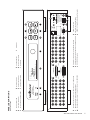
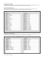
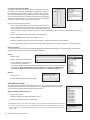
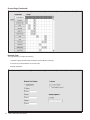
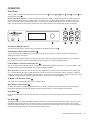
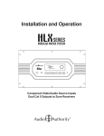
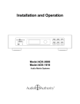
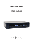
Installation and Operation L 1 2 3 4 5 6 7 8 INPUT L OUTPUT 9 10 11 12 13 14 15 16 INPUT R 1 2 3 4 5 6 7 8 ETHERNET USB SPEED R OUTPUT OUT TO AMPLIFIER ZONES 9 - 16 L LINK OUT TO AMPLIFIER ZONES 1 - 8 R L 9 10 11 12 13 14 15 Model ADX-1616 Audio Matrix 16 800-322-8346 • 859-233-4599 www.audioauthority.com IR R RS-232 SERIAL INPUT 1- SLEEVE = +12V 2- RING = GROUND 3- TIP = SIGNAL 3.5MM IR ADX Series Audio Matrix Switcher ADX-0808 and ADX-1616 Audio Matrix Systems 18V DC POWER ADX Serial Number Custom Installer Telephone Number 2 ADX Audio Matrix User Manual Installation and Operation Manual ADX-0808 and ADX-1616 Audio Matrix Systems Table of Contents Introduction . . . . . . . . . . . . . . . . . . . . . . . . . . . . . . . . . . . . . . . 4 Panel Descriptions. . . . . . . . . . . . . . . . . . . . . . . . . . . . . . . . . . . 5 Getting Started. . . . . . . . . . . . . . . . . . . . . . . . . . . . . . . . . . . . . 6 Installation . . . . . . . . . . . . . . . . . . . . . . . . . . . . . . . . . . . . . . . 7 Configuration. . . . . . . . . . . . . . . . . . . . . . . . . . . . . . . . . . . . . . 7 Operation . . . . . . . . . . . . . . . . . . . . . . . . . . . . . . . . . . . . . . . 13 Using Ethernet, RS-232, and IR. . . . . . . . . . . . . . . . . . . . . . . . . . . .16 Appendix A: Serial and Telnet Commands. . . . . . . . . . . . . . . . . . . . . . .18 Appendix B: Upgrading ADX Firmware . . . . . . . . . . . . . . . . . . . . . . . . 22 Appendix C: Troubleshooting . . . . . . . . . . . . . . . . . . . . . . . . . . . . . 23 Specifications . . . . . . . . . . . . . . . . . . . . . . . . . . . . . . . . . . . . . 23 Limited Warranty. . . . . . . . . . . . . . . . . . . . . . . . . . . . . . . . . . . .24 Audio Authority and the Double-A Symbol are registered trademarks of Audio Authority Corp. Copyright July, 2011, all rights reserved. Audio Authority® Corporation Lexington, Kentucky www.audioauthority.com • 800-322-8346 Warnings To reduce the risk of fire or electric shock, do not expose this unit to rain or moisture. ! • • • • • • • The exclamation point symbol alerts users to important operating and maintenance instructions in this booklet. Read this manual before installing or using this product. This product must be installed by qualified personnel. Do not open the cover—there are no user-serviceable parts inside. Do not expose this unit to excessive heat. Install only in dry, indoor locations. Do not obstruct the ventilation slots. Clean the unit only with a dry or slightly dampened soft cloth. ADX Audio Matrix User Manual 3 INTRODUCTION The ADX is an innovative analog audio matrix with advanced digital signal processing. The DSP features and multiple control interface options make it an excellent solution for audio distribution in residential and commercial applications. Key Features • Sixteen source inputs/sixteen zone outputs (ADX-1616) or eight source inputs/eight zone outputs (ADX-0808) • Advanced DSP features per zone output, including 10-band EQ, multiple filters and tone controls (see below) • Integrates seamlessly with third party control systems such as Control4, URC, RTI and others • Discrete IR and RS-232 codes available for download - use with virtually any third party IR control system • DB-25 quick-connect audio output to Audio Authority amplifiers • Zone grouping (10 groups) and Source/Zone combination presets (10 source/zone combinations) • Global source selection (all zones on to same source) • Simple setup using ADX PC utility via serial, Ethernet or USB drive • 2U rack ears included DSP Features • Custom DSP settings per zone: 10-band Equalization (ZQTM), bass/treble, and more • Low-pass / high-pass filters plus zone grouping feature provides a sub/sat configuration, delivering 2.1 audio to every zone • 10 global EQ presets which can be saved and recalled from any zone • DSP settings can be updated on the fly using serial commands Control Interfaces • Ethernet • RS-232 Serial • Front panel IR sensor • Rear panel IR input (3.5 mm jack or 3-pin header) • Front panel capacitive touch buttons and knob with LCD screen Carton Contents • Model ADX-1616 or ADX-0808 Analog Audio Matrix • 18-volt power supply • Rack ears • User manual Other Materials You May Need • Patch cables (Ethernet, RCA) • Infrared receiver • Third party programmable remote or touchscreen interface • USB 1.1 or USB 2.0 compliant drive 4 ADX Audio Matrix User Manual ADX Audio Matrix User Manual 5 9 1 10 2 11 3 12 4 13 5 14 15 7 16 8 INPUT K INPUT Audio Matrix Switcher ADX Series Analog Audio Output Jacks 1-16 for ADX-1616 or 1-8 for ADX-0808 13 6 M 12 5 DB25 Audio Output to Audio Authority Amplifiers 11 4 B Analog Audio Input Jacks 1-16 for ADX-1616 or 1-8 for ADX-0808 10 3 Favorite Selection Button Group Selection Button Audio Matrix Switcher A INPUT INPUT L 9 2 F E 16 8 Multi Function Knob 15 7 K R L R 1 Vacuum Fluorescent Display (VFD) C L Front Panel IR Receiver B D 14 6 ADX Series Power Indication LED A R shown *ADX-1616 L PANEL DESCRIPTIONS R L OUT TO AMPLIFIER ZONES 9 - 16 L OUT TO AMPLIFIER ZONES 1 - 8 C I P O N H G OUT TO AMPLIFIER ZONES 9 - 16 OUT TO AMPLIFIER ZONES 1 - 8 R L R L 9 1 10 2 11 3 R L R L 9 1 10 2 11 3 12 4 12 4 D J 13 5 13 5 14 6 Dim Button 14 6 15 7 15 7 16 8 16 8 H E RS-232 DB9 Connector USB Connector (For USB Flash Drive Programming Only) Ethernet Connector with Link and Speed Indicators OUTPUT M OUTPUT Back Button Menu Selection Button All Selection Button OUTPUT OUTPUT S R Q N SPEED LINK ETHERNET O USB 18V DC POWER Q 3.5MM IR S 18V DC POWER 5.5MM 18V Center Positive Power Connection 3-Wire IR Input Terminal Block R 1- SLEEVE = +12V 2- RING = GROUND 3- TIP = SIGNAL 800-322-8346 • 859-233-4599 www.audioauthority.com IR 1- SLEEVE = +12V 2- RING = GROUND 3- TIP = SIGNAL 800-322-8346 • 859-233-4599 www.audioauthority.com Model ADX-1616 Audio Matrix INPUT IR J G 3.5MM INPUT IR USB Model ADX-1616 Audio Matrix 3.5MM IR Input Jack P RS-232 SERIAL I F RS-232 SERIAL SPEED LINK ETHERNET GETTING STARTED • Confirm that nothing is missing from your shipping carton. Refer to Carton Contents on page 4. • Record the serial number (found on the product rear panel) in the space provided on the inside front cover of this manual for easy reference. • Activate your warranty and receive future upgrade notifications by registering your purchase at www.audioauthority.com/register. • Read this instruction manual to become familiar with the configurations and functions of this product. Quick Setup Although it is highly recommended that you follow the more detailed installation instructions provided in this manual, a very basic installation may be accomplished by performing the following steps: 1.Connect source equipment to the input jacks 1-16. (Detailed instructions located in the Installation Section.) 2.Connect ADX zone output jacks 1-16 to a multi-channel amplifier OR alternatively, connect the DB-25 audio output to an Audio Authority multi-channel amplifier. (Detailed instructions located in the Installation Section.) 3.Connect the ADX’s power supply to a suitable AC outlet using ONLY the furnished power supply. After a moment, the ADX boots up and is ready to perform switching. Use the front panel controls to select the preferred source input and the zone output number(s) of your preferred listening zones. Choosing a Control Interface The chart below provides an overview of the different range of capabilities when using each control method. For more detailed instructions on the various control methods available, please refer to the following sections: • Controling the ADX through RS-232, see page 16 • Controling the ADX through Ethernet, see page 16 • Controling the ADX through IR, see page 17 • Controling the ADX with the Front Panel, see page 13 Control Interface Capabilities All commands are available on Ethernet and RS-232, but other control methods are limited as shown. RS-232 Ethernet Infrared Audio signal switching X X Dimming X X Lock IR X X Lock front panel interface X X Change Ethernet settings X X Group and Favorite creation X X Group and Favorite switching X X X ADX Audio Matrix User Manual X X X Upgrade firmware 6 Front Panel X X INSTALLATION The ADX is designed so that it may be installed either on a shelf or in a standard 19-inch equipment rack. If rack mounting, remove the feet and the cover screws adjacent to the front panel of the unit. Reuse the cover screws to mount the Model 1192A rack adapters supplied with the ADX. Be sure to place a spacer under the adapters at every screw location. Secure the ADX to the rails of the equipment rack with the screws supplied with the rack adapter kit. Initial Audio Setup Independently test each component to be connected to the ADX prior to system assembly. This will reduce troubleshooting measures later. Verify basic ADX functionality by performing the following steps: SPACER 1.Connect one audio source to a pair of ADX input jacks numbered 1-8. 2.Connect one pair of ADX zone output jacks numbered 1-8 to an audio amplifier. 3.Use high quality cable and keep the lengths as short as possible. 4.Turn on the source, amplifier and the ADX for an initial test. Verify that the audio pathway is performing acceptably by selecting the appropriate source input and zone output from the front panel (detailed instructions for Front Panel operation can be found on page 13). You should now hear the source material being played. If you do not, please refer to the Troubleshooting section found on page 16. If you are still experiencing difficulty, please contact Technical Support by phone at 859-233-4599 or toll free in the US at 1-800-322-8346. 5.Repeat steps 1-4 with jacks numbered 9-16. 6.If no problems have been noted, remove power and continue installation. Input and Output Connections and Testing • Determine the wiring configuration for your setup. Label the RCA cables by the connected device (e.g. Input 1 - Cable Box, Input 2 - Music Server, Zone 1 - Kitchen, Zone - 2 Living Rm etc.). Use good quality RCA cables for optimal results. • Connect the ADX power supply - the unit will immediately power on (there is no power switch). • Apply power to all sources and associated equipment. Use the front panel controls to verify audio signal integrity of sources at each zone location. CONFIGURATION The ADX PC utility is the easiest way to perform advanced setup tasks. Most of these tasks may also be accomplished using serial or Ethernet commands, or via the ADX front panel controls (see page 13). Initial Setup 1. Select Programming Mode: Select the mode you will be using for your ADX configuration. There are three options: • File Mode - (default) requires a USB drive to save and transfer the setup file to the ADX via the back panel USB jack. • Serial Mode - requires a direct serial port connection. • Telnet Mode - requires a connection via a network or a direct Ethernet connection. 2a. Create A New ADX Configuration: If you are setting up a new ADX, start with “new ADX-0808” or “new ADX-1616”. 2b. Modify An Existing Configuration: If you are modifying an existing setup, import the current setup file. ADX Audio Matrix User Manual 7 Configuration File Page This page provides a quick look at all commands and command descriptions in the existing configuration file, primarily used for diagnostics and troubleshooting. In most cases this information should not be modified. Source/Zone Naming Page This page lists all current Zone and Source Names. To change the names of zones and sources, double click in the appropriate field and type in your changes. Use up or down arrow keys to move to the next field. Favorite/Group Naming Page This page lists all current configured Favorites and Groups. To change the names of Favorites and Groups, double click in the appropriate field and type in your changes. Use up or down arrow keys to move to the next field. 8 ADX Audio Matrix User Manual Zone Audio Controls Page This page includes all software tools required to modify zone-specific DSP settings for the ADX. Below is a summary of each tool: 10-band Zone Equalization (ZQ Mode) 1. Select the zone you wish to adjust 2. Select ZQ Mode from the DSP Mode dropdown menu 3. Make desired EQ adjustments for any of the 10 available frequency bands* Save ZQ settings to an EQ File Occassionaly, it may be desired to save a zone’s ZQ settings to an EQ file so that those settings can be used in future installations. This is accomplished using the following steps: 1. Select the zone from which you wish to copy settings. 2. Select ZQ Mode from the DSP Mode dropdown menu. 3. Under the PC Quick EQ Presets section, click the “Save” button. 4. Name the new EQ file. 5. The EQ file is now saved in a folder on your computer for use in other projects. To recall, the EQ file must reside in the same folder with the PC Utility. Global EQ Presets (Preset Mode) The ADX includes 10 built-in “Global” EQ presets, which can be used by any ADX zone. By default, all 10 EQ presets are flat. Adjusment of global EQ presets is accomplished using the ADX EQ Presets page (See page 10). Once all EQ presets have been set up, preset mode can recall any global preset to a zone. 1. First, make sure the desired EQ preset has been set up on the ADX EQ Presets page. 2. Select Preset Mode from the DSP Mode dropdown menu. 3. Select a zone. 4. Select the desired EQ preset from the ADX EQ Preset dropdown menu*. Bass & Treble (Tone Controls) 1. Select the zone you wish to adjust. 2. Select Tone Controls from the DSP Mode dropdown menu. 3. Make any desired bass and treble adjustments*. *IMPORTANT NOTE: In order to hear your changes, you must transfer all utility settings into the ADX using the “export” option from the File menu. For real-time ZQ adjustment and monitoring, EQ presets, bass & treble changes, etc. program the serial commands into a remote control system such as URC, Command Fusion, or RTI. ADX Audio Matrix User Manual 9 Low-Pass Filter (Low-Pass Mode) This mode is used to turn any zone output into a dedicated mono lowpass output for a subwoofer. Additionally, a low-pass zone output can be grouped with a full range zone output to create a single 2.1 audio zone. IR and serial group commands (source, volume, and mute) can then be used to control both outputs (low-pass and full range) together. See page 11 for instructions on how to set up a zone group and page 18 for source, volume and mute group serial commands. How to set up a low-pass zone output: 1.On the Source/Zone Naming page, select and name a zone you wish to designate as a low-pass output. If you are grouping a lowpass zone with a full-range zone, it is recommended to name your zones in pairs for clarity. For example, if Zone 1 is labeled “Master BR”, Zone 2 should be labeled “Master BR Sub”, and so on. 2.On the Zone Audio Controls page, select a zone for low-pass. 3.Select Lowpass from the DSP Mode dropdown menu. 4.Make any desired changes to the Crossover Frequency. Range of adjustment is 40Hz to 240Hz*. 5.On the Groups page, group the low-pass zone output with a full-range zone output (See page 11 for more information). EQ/Tone Disabled If no EQ or tone mode is desired select EQ/Tone Disabled from the DSP Mode dropdown. All levels will be flat, but previous settings can be recalled by switching back to ZQ or Tone Mode. Volume 1.Select a zone. 2.Adjust volume to the desired level*. 3.If your installation requires a fixed volume level from the ADX (i.e. volume level is adjusted through an external amplifier or volume control), select the “Volume Lock” setting. When an ADX zone is set to “Volume Lock”, it ignores all ADX volume up/down commands (Serial, Telnet or IR) and remains at a fixed full output level. Balance 1.Select a zone. 2.Adjust left/right balance levels accordingly*. ADX EQ Presets Page The ADX includes 10 built-in “Global” EQ presets, which can be used by any zone. By default, all 10 EQ presets are flat and require adjustment for use. The ADX EQ Presets Page allows you to name all 10 presets and adjust band settings for each. Modify and Store Global EQ Presets 1.Select a ZQ preset. 2.Name the preset in the ADX Preset Name text box. 3.Make any desired adjustments to EQ sliders*. * IMPORTANT NOTE: In order to hear your changes, you must transfer all utility settings into the ADX using the “export” option from the File menu. For real-time ZQ adjustment and monitoring, EQ presets, bass & treble changes, etc. program the serial commands into a remote control system such as URC, Command Fusion, or RTI. 10 ADX Audio Matrix User Manual ADX EQ Presets Page (Continued) Save EQ Preset to an EQ File Occassionaly, it may be desired to save a global preset’s EQ settings to an EQ file so that those settings can be used in future installations. This is accomplished using the following steps: 1.Select the EQ preset you wish to copy settings from. 2.Under the PC Quick EQ Presets section, click the “Save” button. 4.Name the EQ file. 5.The EQ file is now saved in a folder on your computer for use in other projects. To recall, the EQ file must reside in the same folder with the PC Utility. Favorites Page This page allows you to quickly setup zone & source combination audio “scenes” such as party, dinner, game night, etc. All favorites can then be recalled with a dedicated serial or IR command or from the front panel of the ADX. To set up a favorite, use the following steps: 1.Label your favorites on the Favorite/Group Naming page (See page 8). 2.Back on the Favorites page select a favorite name from the “Choose a Favorite” list. 3.Double click the junction between a zone and a source to include a source/zone combination into a favorite scene. 4.Repeat this step for all other source/zone combinations you desire to be included in the favorite scene. 5.Follow steps 2-4 above for all additional favorites. Groups Page Use this page to put several zones into a group. Groups are useful for controlling several zones at the same time with volume, source selection and mute commands. You can also create 2.1 audio zones (a full-range and a low-pass zone output joined together) using the group feature. (More on low-pass mode: page 10.) To set up a group, use the following steps: 1.Label groups on the Favorite/Group Naming page. 2.On the Groups page (illustration on page 12) double click the junction between a zone and a group to include a zone in a group. The group name is displayed in the upper left corner when you click on a junction square. 3.Repeat this step for all other zone/group combinations desired. ADX Audio Matrix User Manual 11 Groups Page (Continued) Network Page This page allows you to adjust the following: 1.Network settings (Enable DHCP, IP Address, Network Mask & Gateway). 2.Lockouts (Front Panel Buttons & Front Panel IR). 3.Display brightness. 12 ADX Audio Matrix User Manual L 1 2 3 4 5 6 7 8 INPUT OUTPUT R L 1 2 3 4 5 6 7 8 ETHERNET USB LINK OUT TO AMPLIFIER ZONES 1 - 8 SPEED R OPERATION L R 9 10 11 12 13 Front Panel 14 15 16 INPUT OUTPUT OUT TO AMPLIFIER ZONES 9 - 16 L 9 10 11 12 13 14 15 Model ADX-1616 Audio Matrix 16 800-322-8346 • 859-233-4599 www.audioauthority.com IR RS-232 SERIAL R 1- SLEEVE = +12V 2- RING = GROUND 3- TIP = SIGNAL The front panel is operated by using six touch sensitive keys: Group E , Favorite F , All G , Menu H , Back I , and Dim J and a Multi-Function Knob D . 3.5MM INPUT 18V DC POWER IR Multi-Function Knob Operation: Used to navigate through all menu items, the multi-function knob can scroll (clockwise or counterclockwise) and select or de-select (press in). The open arrow symbol is displayed when scrolling through menu items. Once an item has been selected (by pressing in the knob), the arrow will fill in . Next, turn the knob to adjust the value. Finally, press in the knob again to de-select the menu item and scroll to the next item that needs to be adjusted. E F G H I J ADX Series Audio Matrix Switcher D Zone/Source Selection Screen This default screen performs zone and source switching via the Multi-Function Knob D . Group Button > Group Selection Screen E This screen displays all configured groups and allows for group source selection. To learn more about zone groups and defining zone groups, see page 11. About Groups: The ADX is capable of storing up to 10 Groups. Each group may be assigned a name up to 16 characters long. Groups can only be created using the ADX PC utility (see page 11) or serial commands (page 19). Favorite Button > Favorite Selection Screen F This screen displays all configured favorites. To learn more about defining favorites, see page 11. To select a favorite, rotate the knob until the desired favorite is listed, then press in the knob to activate it. About Favorites: Favorites are unique zone and source combinations, or audio “scenes” such as party, dinner, game night, etc. Favorites allow the end user to recall these audio scenes with a remote or touchscreen control. The ADX is capable of storing up to 10 Favorites. Each Favorite may be assigned a unique name up to 16 characters in length. Favorites can only be configured and named using the ADX PC utility (see page 11) or with serial commands (page 20). All Button > All Selection Screen G This screen allows switching all output zones to a single source. Menu Button > Menu Screen H Press the Menu Button to access the following sub-menus: Volume, Equalizer, Tone/Lowpass, Balance, Network Settings, Export File, Import File, Front Panel IR, Display Settings, Firmware Versions, Firware Update, Factory Default. Back Button I Pressing this button returns you to the previous screen. Press the back button repeatedly to return to the default Zone/Source screen. Dim Button J This button toggles through four predefined brightness levels for the VFD and panel LED indicators. After a set period of time (adjustable using the front panel or in the ADX PC utility), the VFD will enter a screen saver mode and turn off. The power and button LED’s will remain on at a very low level to show that the unit is receiving power. Any key press or knob adjustment returns the VFD and LED indicators to the last selected brightness level. ADX Audio Matrix User Manual 13 Volume Adjusts the volume level (measured in dB) for each zone output. Displays real-time zone output level meters and source selection. Scroll past 0 db to set a zone output to “fixed.” See page 10 for more information on fixed volume applications. Equalizer (ZQ Mode and EQ Preset Mode) Use to switch between ZQ Mode (10-band zone EQ) or EQ Preset Mode (10 Global EQ presets assignable to any zone). Both ZQ and EQ Preset Modes allow for adjustment of all 10 bands of equalization. EQ can be bypassed by selecting “EQ Disabled”. All ten frequencies are reset to flat, but returning to either EQ mode recalls the last settings. Tone/Lowpass Use to switch between Tone Mode or Lowpass Mode. Tone Mode allows for adjustment of bass and treble levels and Lowpass Mode allows for adjustment of the crossover frequency of a zone’s low-pass filter. Lowpass mode is used to assign a zone output to a dedicated subwoofer. Additionaly, a low-pass zone output can be grouped together with a full range zone output (using ADX PC utility) for a 2.1 audio “zone”. See page 10 for more information on setting up a lowpass zone in the ADX PC utility. Tone and Lowpass filters can be bypassed by selecting “Tone/LP Disabled”. Balance Use to adjust the Left/Right stereo balance (measured in db) for a zone output. Also displays real-time Left/Right balance level meters. Network Settings Displays the current network settings of the ADX. See page 12 for more information on Network Settings. Export File With a USB 1.1 or USB 2.0 drive connected to the USB port O on the rear panel of the ADX, follow the on screen instructions to export to the default file name, “config.adx”. If the file is already present, you will be prompted to overwrite it. Note – The USB port is v1.1 and v2.0 compatible. There is a small delay when inserting a USB drive in order to identify the device and mount the file system. Although many different drives were tested successfully with the system, not all USB drives will work with the ADX. Tested file systems include FAT and FAT32. Import File This selection imports the configuration settings from a text file on a USB drive. Simply follow the on screen instructions to select the file to import, which must have the “*.adx” format. Once the file has been selected, the fourth line of the screen displays the commands as they are read from the file and a serial/telnet connection details the commands read and their execution status. Front Panel IR This screen allows the front panel IR receiver to be turned on or off. Factory default is off. 14 ADX Audio Matrix User Manual Display Settings Shows current settings for the front panel display: Sleep timer (screen timeout) and display brightness. The sleep timer can be set to 5, 2 and 1 minute(s) or Disabled. Brightness can be set to 25%, 50%, 75% or 100%. Firmware Versions Displays the firmware versions of the primary firmware and the boot-loader. Firmware Update Use to load firmware updates to the ADX using a USB drive. Follow on-screen instructions and/or the text file instructions included with online firmware updates. Factory Defaults Use to restore all ADX settings to factory default. Follow on-screen instructions. ADX Audio Matrix User Manual 15 USING SERIAL AND ETHERNET (TELNET) Follow the instructions for your Control4, RTI, URC, or other controller to connect to the ADX using the serial settings below, and/or Ethernet settings accessible via the ADX front panel menu. All of the commands listed in Appendix A can be used via telnet or serial connection. •At idle, the ADX checks for received serial or telnet data every 200 ms. Once data has been received, it checks every 1 ms to handle rapid groups of commands and macros. After 100 ms of inactivity, it returns to checking at intervals of 200 ms. •The ADX telnet server allows two clients to be connected at one time. Each client connection has a time out of 15 minutes; if a client crashes and does not close the connection properly (sending an EOF) that connection remains busy until it times out. Connecting to the ADX RS-232 Port System controllers and PCs can send all setup and control commands as well as receive feedback via the RS-232 serial port. • Important: If a PC is connected directly to the ADX RS-232 port, use a standard serial cable. • Communication Settings: baud rate is 9600 bps, 8 data bits, no parity, 1 stop bit, and no flow control. • See the table and diagram below for the ADX serial port pinout. Transfer Rate 9600 bps Data Bits 8 Parity None Stop Bits 1 Flow Control None or Off Character type ASCII Connector DB-9 GND RX TX 5 4 3 2 1 9 8 7 6 DB-9 connector Electrical Rating Pins 2 and 3, ±15 VDC Pin out Pin 2, Tx (Standard cable) Pin 3, Rx P on rear panel of ADX. Pin 5, Ground Shell, Ground Using a Computer via Ethernet To use a PC or Mac with the ADX, use a telnet client or terminal program to send commands (listed in Appendix A) through the Ethernet port on the ADX. Connect a computer directly to the Ethernet port using a crossover cable, or alternatively use a standard Ethernet hub or switch and a standard patch cable. Once connected to a computer or network, the ADX by default attempts to obtain an IP address automatically using DHCP. To use static settings, see the detailed instructions on page 17 or serial commands on page 21. 1 located2 next to the 3 4 7 that help 8 to OUTPUT There are two LED indicators Ethernet port 5N on the6rear panel L identify connection issues: UT OUT TO AMPLIFIER • Link1 -- 8The ZONES Link LED is steadily lit if a connection is detected and flashes when activity is present. R ETHERNET LINK SPEED • Speed - The Speed LED is off for 10 base T, and on for 100 base T. UT OUTPUT OUT TO AMPLIFIER ZONES 9 - 16 L 9 10 11 12 13 14 15 Model AD 16 800-322www.a IR R RS-232 SERIAL INPUT 1- SLEEV 2- RING 3- TIP = S 3.5MM IR 16 ADX Audio Matrix User Manual DHCP DHCP is enabled on the ADX by default. If DHCP is enabled on your network, simply connecting the ADX to the network with an existing DHCP server enables it to obtain all necessary information. Static Addressing Connected Directly to a PC The ADX must be given an IP address which will not conflict with the PC. Go to the network settings (which are found in control panel -> network -> local connection properties of a PC running Windows XP). Change the TCP/IP protocol properties, and set the IP address, gateway, and subnet mask, if they are not already set. This can be arbitrarily done on a direct connection, but a good choice for the settings would be IP address of 192.168.0.1, subnet mask of 255.255.255.0, and an empty default gateway. Once these values have been set, use serial commands (page 21) to set the network settings of the ADX in a similar manner, but use a different IP address than that of the computer (for example, 192.168.0.2). Static Addressing on a Network The ADX must be set to the same settings as the PC except for the IP address, which must not conflict with anything else on the network. To determine this in Windows, use the DOS prompt (Start->Run->cmd) commands ipconfig and ping. Ipconfig lists the PC’s settings, and ping tests addresses to make sure that nothing else on the network has that address. Enlist the help of a network administrator if you are unfamiliar with setting up a network connection. Once a connection is established, a telnet program such as Hyper Terminal, Teraterm, PuTTY etc, must be used to connect to the device. Enter the IP address of the ADX and leave the default port (23) to connect. Once connected, standard serial commands (listed in Appendix A) can be issued in an identical manner to serial control. ADX screen image showing Network Settings with DHCP set to ON, with no link established. Using an IR Control System The ADX uses a three wire IR circuit. It is imperative that the correct polarity be maintained when connecting third party IR equipment. The 3.5mm pinout is shown in the illustration below and the connecting block pinout is screen printed on the back panel of the ADX. Patch the IR signal from your IR receiver directly to the IR input port on the rear panel using the connection method of your choice. Alternatively, adhere an IR emitter from your infrared system onto the ADX front panel IR sensor. Tip = Signal Ring = Ground Sleeve = +12 Volts If the ADX IR codes are available from your remote control company, download and/or activate those files. A CCF file containing the latest codes can be downloaded from the Audio Authority website, www.audioauthority.com/page/ir. Tips for Using Infrared Control • If you are using standard hand-held IR remote controls, ensure correct operation by avoiding sources of light pollution such as Plasma and LCD TVs, direct sunlight, fluorescent light, etc. Experiment with the physical placement of the IR sensor to avoid interference. • If a source of interference cannot be eliminated or avoided, use IR sensors that block that type of interference, such as Plasma-proof or LCD-proof sensors. In addition to basic IR commands, discrete IR commands are now available for download at www.audioauthority.com such as: • Connecting a zone to a source • Mute on/off and mute toggle a zone • Volume up/down in a zone • Balance left/right/center in a zone • Bass up/down/flat in a zone • Treble up/down/flat in a zone • Connecting a group to a source • Group volume up/down • Group mute on/off/toggle ADX Audio Matrix User Manual 17 Appendix A: Serial and Telnet Commands Zone Commands Description Structure Example Reply Result Switch a zone to a source input [CO###I##] [CO1I2] (CO1I2) Zone output 1 is connected to source input 2 Switch all zones to one source input [CXI##] [CXI4] (CXI4) All zone outputs are connected to source input 4 Zone volume up one step [VO##U] [VO3U] (VO3R-20) Zone 3 volume increased one step to -20 dB Zone volume down one step [VO##D] [VO3D] (VO3R-21) Zone 3 volume decreased one step to -21 dB Set zone volume level [VO##R##] [VO1R-10] (VO1R-10) Zone 1 volume is -10 dB, Range: -80 to 0 dB Zone mute [VMO##] [VMO1] (VMO1) Zone 1 output is muted Zone unmute [VUMO##] [VUMO3] (VUMO3) Unmute Zone 3 and set to previous volume level Zone mute toggle [VMTO##] [VMTO2] (VMO2) or (VUMO2) Zone 2 is muted or Zone 2 is returns to previous volume level Increment balance to the left [BO##LU] [BO5LU] (BO5L40) Zone 5 balance adjusted to the left, now +40 Increment balance to the right [BO##RU] [BO5RU] (BO5L39) Zone 5 balance adjusted to the right, now +39 Balance to the center [BO##R0] or [BO##L0] [BO1R0] or [BO1L0] (BO1R0) (BO1L0) Zone 1 balance is centered Set balance level left [BO##L##] [BO7L70] (BO7L70) Zone 7 balance is left +70 Range: 0 to +80, 0 = center Set balance level right [BO##R##] [BO7R25] (BO7R25) Zone 7 balance is right +25 Range: 0 to +80, 0 = center Set to lowpass mode [EO##M4] [EO2M4] (EO2M4) Zone 2 is in lowpass mode and mono (subwoofer) Set lowpass crossover frequency [EO##LP##] [EO2LP115] (EO2LP115) Lowpass filter for Zone 2 is now 115 Hz Range: 40 Hz to 240 Hz Set to tone mode [EO##M3] [EO2M3] (EO2M3) Zone 2 is switched to tone mode (bass/treble) Bass up/down one step [TO##BU] [TO##BD] [TO16BU] [TO16BD] (TO16B10T0) (TO16B9T0) Zone 16 bass level increased to +10 dB Zone 16 bass level decreased to +9 dB Treble up/down one step [TO##TU] [TO##TD] [TO8TU] [TO8TD] (TO8B9T1) (TO8B9T0) Zone 8 treble level increased to +1 dB Zone 8 treble level decreased to 0 dB Set bass/treble level [TO##B##T##] [TO2B-3T9] [TO2B0T0] (TO2B-3T9) (TO2B0T0) Zone 2 bass is -3 dB and treble is +9 dB Zone 2 bass/treble = flat Range: -12 to +12 dB, 0 = flat Set to ZQ mode [EO##M1] [EO4M1] (EO4M1) Zone 4 is switched to ZQ mode ZQ band up/down one step [EO##B##U] [EO##B##D] [EO3B1U] [EO3B1D] (EO3B1L6) (EO3B1L5) Zone 3, EQ band 1 increased to +6 dB Zone 3, EQ band 1 decreased to +5 dB Set ZQ band level [EO##B##L##] [EO12B2L-4] [EO12B2L0] (EO12B2L-4) (EO12B2L0) Zone 12, EQ band 2 is set to -4 dB Zone 12, EQ band 2 is set to unity gain (0) Range: -10 to +10 per band, 0 = flat Save ZQ settings to EQ preset [EO##STP##] [EO5STP2] (EO5STP2) Saves zone 5 ZQ settings to preset #2 Zone must be in ZQ mode. 10 presets available. SOURCE SELECT VOLUME MUTING BALANCE LOWPASS MODE TONE MODE (BASS & TREBLE) ZQ MODE (10-BAND ZONE EQ) EQ PRESET MODE (GLOBAL EQ PRESETS) 18 Set zone to EQ preset mode [EO##M2] [EO9M2] (EO9M2) Zone 9 is switched to EQ preset mode Query an EQ preset [QEP##] [QEP8] (EP8N“JAZZ”) (EP8B1L2) (EP8B2L2) (EP8B3L1) (EP8B4L0) (EP8B5L-1) (EP8B6L2) (EP8B7L3) (EP8B8L5) (EP8B9L0) (EP8B10L2) (QEP8) Preset 8 name is JAZZ EQ band 1 level = +2 EQ band 2 level = +2 EQ band 3 level = +1 EQ band 4 level = 0 EQ band 5 level = -1 EQ band 6 level = +2 EQ band 7 level = +3 EQ band 8 level = +5 EQ band 9 level = 0 EQ band 10 level = +2 ADX Audio Matrix User Manual Zone Commands (Continued) Description Structure Example Reply Result Adjust EQ preset band up/down [EP##B##U] [EP##B##D] [EP9B1U] [EP9B1D] (EP9B1L3) (EP9B1L2) EQ preset 9, band 1 increased to +3 dB EQ preset 9, band 1 decreased to +2 dB Set EQ preset band level [EP##B##L##] [EP2B9L-6] [EP2B9L0] (EP2B9L-6) (EP2B9L0) EQ preset 2, band 9 is set to -6 dB EQ preset 2, band 9 is set to unity gain (0) Range: -10 to +10 per band, 0 = flat Apply EQ preset to a zone [EO##P##] [EO7P3] (EO7P3) Zone 7 is now in preset mode, using preset 3 Query volume status [QVO##] [QVO16] (VO16R-30) Zone 16 volume level is -30 dB Query mute status [QVMO##] [QVMO7] (VMO7) Zone 7 is muted Query a zone’s source connection [QCO###] [QCO4] (CO4I1) Zone output 4 is connected to source input 1 Query all information about a zone [QO###] [QO8] (EO8M0) (BO8L0) (VO8R-12) (VUMO8) (CO8I4) (NO8”POOL”) (QO8) DSP mode=2 (Tone) Balance=0 (Flat) volume is set to -12 not muted source input 4 selected the name of the zone is POOL Name an output zone [NO###“@”] [NO3“Den”] (NO3“Den”) Zone 3 is named “Den” Name an input source [NI##“@”] [NI3“ipod”] (NI3“ipod”) Source 3 is named “ipod” Structure Example Reply Result [CG##I##] [CG2I4] (CG2I4) All zones in group 2 switch to source input 4 Group volume up one step [VG##U] [VG7U] (VG7R-4) Group 7 volume increased one step dB to -4 dB Group volume down one step [VG##D] [VG7D] (VG7R-5) Group 7 volume is decreased one step to -5 dB Set group volume level [VG##R##] [VG1R-10] (VG1R-10) Group 1 volume is -10 dB, Range: -80 to 0 dB Mute a group [VMG##] [VMG4] (VMG4) Group 1 output is muted Unmute a group [VUMG##] [VUMG4] (VUMG4) Unmute Group 1, set to previous volume level Mute toggle a group [VMTG##] [VMTG3] (VMG3) or (VUMG3) Group 3 is muted or Group 3 returns to previous volume level [QG##] [QG10] (G10A5) (G10A9) (NG10“GUEST”) (QG10) Group 10 members include zones 5 and 9, group name is “GUEST” Add a zone to a group [G##AO###] [G1AO3] (G1AO3) Zone 3 is now a member of group 1 Remove a zone from a group [G##RO###] [G1RO3] (G1RO3) Zone 3 is removed from group 1 Name a group [NG##“@”] [NG1“Bedrms”] (NG1“Bedrms”) Group 1 is named “Bedrms” Erase all group members [GAR] [GAR] (GAR) All groups are empty (no member zones) ZONE QUERY COMMANDS MISCELLANEOUS Group Commands Description SOURCE SELECT Switch a group to a source input VOLUME MUTE GROUP QUERY Query a group MISCELLANEOUS ADX Audio Matrix User Manual 19 Favorites Description Structure Example Reply Result Connect a favorite [CF##] [CF3] (CF3) Favorite 3 is now connected Add zone/source combination to a favorite [F##AO##I##] [F1AO3I2] (F1AO3I2) Favorite 1 now includes zone 3/source 2 Query a favorite [QF##] [QF10] (F1AO1I3) (F1AO3I4) (NF1“Favorite 1 Name”) (QF10) Query favorite membership and settings. See the favorite adding and naming commands for how to read the results Remove a zone/source combination from a favorite [F##RO###] [F1RO3] (F1RO3) Remove zone 3 from favorite 1 Name a favorite [NF##“@”] [NF1“Gameday”] (NF1“Gameday”) Favorite 1 is named “Gameday” Erase all favorite memberships [FAR] [FAR] (FAR) All favorites are empty (no member zones) Front Panel Interface Adjustment Description Structure Example Reply Result Query front panel interface [QFPL] [QFPL] (FPL0) (QFPL) Front panel interface is locked out (1) or Lock or unlock front panel interface [FPL#] [FPL0] [FPL1] (FPL0) (FPL1) Front panel interface is locked out (1) or unlocked (0) Query front panel IR lockout [QIRL] [QIRL] (IRL0) (QIRL) Front panel IR is disabled (1) Front panel IR is enabled (0) Enabled or disable front panel IR [IRL#] [IRL1] [IRL0] (IRL1) (IRL0) Front panel IR sensor off or disabled (1) Front panel IR sensor on or enabled (0) Dim front panel display and controls [SD#] [SD1] (SD1) Shows screen and LED brightness setting Range: 0-3 Description Structure Example Reply Result Query the current configuration [QX] [QX] (SC100) (SD4) (SBL100) (SLED100) (DHCP1) … All configuration information is returned in parentheses Editable configuration or backup [QXSB] [QXSB] [SC100] [SD4] [SBL100] [SLED100] [DHCP1] … All configuration information is returned in square brackets that can be edited and/or reloaded into the ADX to restore settings Load the backup configuration [LOAD] [LOAD] (LOAD) Loads a configuration from output in square brackets Reset configuration to factory defaults [RESET] [RESET] (RESET) Loads the factory default settings for every option Save the current configuration to active memory [SAVE] [SAVE] (SAVE) Saves current configuration settings immediately; ADX auto-saves settings every 30 seconds during normal operation lockout unlocked (0) Configuration Utilities 20 ADX Audio Matrix User Manual Network Settings Adjustment Note: Network settings are stored but not committed until the [EC] command is sent, or ADX power is cycled. The [SAVE] command does not commit network settings. Description Structure Example Reply Result Query current network (Ethernet) settings [QE] [QE] (DHCP1) (IP0.0.0.0) (NM0.0.0.0) (GW0.0.0.0) (MAC0000-5E-A8- 00-D3) DHCP status, IP address, subnet mask, gateway, and MAC address are displayed by this command Enable or disable dynamic host configuration protocol (DHCP) [DHCP#] [DHCP1] [DHCP0] (DHCP1) (DHCP0) DHCP is enabled (1) or disabled (0) It is not possible to set a static IP address while DHCP is on Define the static IP address [IP###.###.###.###] [IP192.168.0.212] (IP192.168.0.212) Set the IP address to the specified value Define the default gateway [GW###.###.###.###] [GW192.168.0.2] (GW192.168.0.2) Set the default gateway for accessing computers outside of the subnet Define the subnet mask [NM###.###.###.###] [NM255.255.255.0] (NM255.255.255.0) Set subnet mask (determines devices accessible without traveling through the gateway) Commit network settings [EC] [EC] (EC) This command makes it possible to set a static IP/gateway/network mask over telnet without being disconnected ADX Audio Matrix User Manual 21 Appendix B: Firmware Update Procedures The latest version of firmware is available for download from www.audioauthority.com/page/firmware. To update version 1.2.0 and later to the latest version: 1. Copy the firmware file (e.g. “adx_v200.s19”) onto a USB drive. 2. Insert the drive in the USB port on the rear panel of the ADX. 3. Press the menu key and navigate the firmware update menu item. 4. Follow the prompts and select the firmware file. If you see this screen, make sure the firmware file is named correctly and is on the root level of the USB drive. 5. After a short delay the ADX reboots and performs the firmware update. 6. Once the update has finished, the ADX reboots and resumes operation with the new firmware version. Push to select the firmware file. To update version 1.0.1b and earlier to the latest version: 1. Copy the firmware file (e.g. “adx_v200.s19”) onto a USB drive. 2. Insert the drive in the USB port on the rear panel of the ADX. Cycle ADX power. 3. During boot up, the front panel displays “Push knob for firmware update.” Press the front panel knob. 4. Follow the prompts to update the system card firmware and reboot the ADX. 22 ADX Audio Matrix User Manual Appendix C: Troubleshooting Symptom Possible Cause No power • Check for available AC power from the wall outlet. • Check to make sure there is 18V available from the provided power supply. If not, remove the power supply from the wall and reconnect. No Audio • Check for proper operation of Source and Receiver. • Ensure cabling between the ADX and third party equipment is good and connected properly. • Ensure power is connected to the ADX. • Check volume levels at receiver and in ADX controls. No Ethernet Control • Refer to Page 16 and Appendix A for Ethernet Setup and Control. If problem persists, contact your Installer or Network Administrator for assistance. No RS232 Response • Make sure the Baud Rate matches between the ADX and the Serial Terminal program being used to issue commands. ADX Default = 9600 • Make sure Flow Control is turned off. • Check cable pinout for compatibility between ADX and control equipment. No USB Response • Ensure the USB storage device you are using is USB 1.1 or USB 2.0 compliant. • Some USB storage devices may not be compatible with the ADX. If your device meets the standard requirements but will not function with the ADX, try using a different USB storage device. No IR Response • Check the menu to see if front panel IR sensor is enabled. (It is disabled by default.) • Ensure proper connection and operation of any external IR sensor. If you have applied the above troubleshooting suggestions and are still experiencing difficulties, contact Audio Authority Technical Support by phone at 1-859-233-4599 or toll free within the US at 1-800-322-8346. You can also email Technical Support at [email protected]. Specifications Analog/Digital Analog Agency Approvals FCC Digital Input/Output Type N/A DC Input Connector 5.5 x 2.1mm Input Impedance 100K DC Input Voltage/Polarity 18V Center Positive Min Load Impedance 10K Max DC Input Current 600mA/1.1A Multi-channel Digital N/A Power Supply 571-014/571-023 Frequency Response 10-25kHz Heat Output 38/68 BTU/hr S/N Ratio 82dB THD+Noise 0.02% Crosstalk -85dB ADX Audio Matrix User Manual 23 Limited Warranty If this product fails due to defects in materials or workmanship within one year from the date of the original sale to the end-user, Audio Authority guarantees that we will replace the defective product at no cost. Freight charges for the replacement unit will be paid by Audio Authority (Ground service only). A copy of the invoice from an Authorized Reseller showing the item number and date of purchase (proof-of-purchase) must be submitted with the defective unit to constitute a valid in-warranty claim. Units that fail after the warranty period has expired may be returned to the factory for repair at a nominal charge, if not damaged beyond the point of repair. All freight charges for out-of-warranty returns for repair are the responsibility of the customer. Units returned for repair must have a Customer Return Authorization Number assigned by the factory. This is a limited warranty and is not applicable for products which, in our opinion, have been damaged, altered, abused, misused, or improperly installed. Audio Authority makes no other warranties either expressed or implied, including limitation warranties as to merchantability or fitness for a particular purpose. Additionally, there are no allowances or credits available for service work or installation performed in the field by the end user. 2048 Mercer Road, Lexington, Kentucky 40511-1071 Phone: 859/233-4599 • Fax: 859/233-4510 Customer Toll-Free USA & Canada: 800/322-8346 Website: http://www.audioauthority.com 752-598 3/13