1
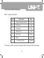
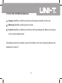
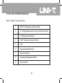
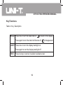
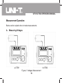
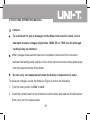
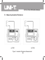
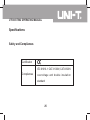
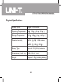
UT501/UT502 OPERATING MANUAL
Table of Contents
Title
Page
Introduction
4
Unpacking the Meter
4
Safety Information
6
International Electrical Symbols
11
The Meter Structure
12
Key Functions
14
Rotary Switch
15
Measurement Operation
16
A. Measuring Voltages
16
B. Measuring Insulation Resistance
18
1
UT501/UT502 OPERATING MANUAL
Maintenance
21
A.
General Service
21
B.
Replacing the Battery
23
Specifications
25
Safety and Compliances
25
Physical Specifications
26
General Specifications
27
Feature Summary
27
Detailed Accuracy Specifications
28
A.
Voltage Measurement
28
B.
UT501: Insulation Resistance Measurement
29
UT502: Insulation Resistance Measurement
30
2
UT501/UT502 OPERATING MANUAL
List of Tables
Table
Title
1.
Unpacking Inspection
Page
5
2.
International Electrical Symbols
11
3.
Meter Front Description
13
4.
Key Description
14
5.
Rotary Switch Description
15
List of Figures
Figure
Title
Page
1.
The Meter Front Structure
12
2.
Voltages Measurement
16
3.
Insulation Resistance Measurement
18
4.
Battery Replacement
23
3
UT501/UT502 OPERATING MANUAL
Introduction
Uni-Trend Model UT501 and UT502 insulation resistance tester (hereafter, "the Meter")
is a handheld instrument designed primarily to make resistance/ insulation resistance,
DC/AC Voltage measurement.
Unpacking the Meter
The Meter includes the following items:
4
UT501/UT502 OPERATING MANUAL
Table 1. Unpacking Inspection
Item
Description
Qty
1
English Operating Manual
1 piece
2
Test Lead
1 set
3
Test probe
1 set
4
Alligator clip
1 set
5
Carry bag
1 piece
6
Strap
1 piece
5
1.5V Battery (LR14)
6 pieces
In the event you find any missing or damage, please contact your dealer immediately.
5
UT501/UT502 OPERATING MANUAL
Safety Information
This Meter complies with the standards IEC61010 -1 safety measurement requirement:
in pollution degree 2, overvoltage category (CAT. III 600V, CAT.II 1000V) and double
insulation.
CAT II: Local level, appliance, portable equipment etc., with smaller transient voltage
overvoltages than CAT. III
CAT III: Distribution level, fixed installation, with smaller transient over voltages than
CAT. IV
Use the Meter only as specified in this operating manual, otherwise the protection
provided by the Meter may be impaired.
6
UT501/UT502 OPERATING MANUAL
Danger identifies conditions and actions that pose hazard(s) to the user.
Warning identifies avoiding electric shock.
Caution identifies conditions and actions that may damage the Meter and carrying
out accurate measurement.
International electrical symbols used on the Meter and in this Operating Manual are
explained on page 11.
7
UT501/UT502 OPERATING MANUAL
Danger
Use of instrument in a manual not specifed by the manufactuer may impair
safety features/protection provided by the equipment. Read the following safety
information carefully before using or servicing the instrument.
Do not apply more than 1000V DC or 750V AC.
Do not use the Meter around explosive gas, vapor or dust.
Do not use the Meter in a wet environment.
When using the test leads, keep your figures away from the lead contacts.
Keep your figures behind the finger guards on the leads.
Do not use the Meter with any parts or cover removed.
When carrying out insulation measurement, do not contact the circuit
under test.
8
UT501/UT502 OPERATING MANUAL
Warning
Do not use the Meter if it is damaged or metal part is exposed. Look for
cracks or missing plastic.
Be careful when working above 30V rms, 46.7V ac rms and 70V DC. Such
voltages pose a shock hazard.
Do not change battery when the Meter is in wet environment.
Place test leads in proper input terminals. Make sure all the test leads
are firmly connected to the Meterís input terminals.
Make sure the Meter is turned off when opening the battery compartment.
Carefully read the operating manual before operating the Meter.
Follow the operating manual all the time when using the Meter and keep
the operating manual in a safe place.
Wrong operation will cause incident and damage to the Meter.
9
UT501/UT502 OPERATING MANUAL
Caution
When performing resistance tests, remove all power from the circuit to
be measured and discharge all the power.
When servicing the Meter, use only the same model number or identical
electrical specifications of test leads and power adaptor.
Do not use the Meter if the battery indicator (
) shows a battery
empty condition. Take the battery out from the Meter if it is not used
for a long time.
Do not use or store the Meter in an environment of high temperature,
humidity, explosive, inflammable and strong magnetic field. The
performance of the Meter may deteriorate after dampened.
10
UT501/UT502 OPERATING MANUAL
International Electrical Symbols
International symbols on the Meter and in this manual are explained in Table 2.
Table 2. International Electrical Symbols
DCV
ACV
Equipment protected by double or
reinforced insulation.
DC Measurement
AC Measurement
Grounding
See Manual
Conforms to Standards of European
Union
11
UT501/UT502 OPERATING MANUAL
The Meter Structure
Below Figure 1 and Table 3 shows the Meter front structure and description.
a.UT501
b.UT502
Figure 1. The Meter Front Structure
12
UT501/UT502 OPERATING MANUAL
Table 3. Meter Front Description
1
EARTH: Resistance input terminal
2
G: Voltage Measurement input negative terminal
3
V: Voltage input terminal
4
LINE: Resistance input terminal
5
LCD
6
Display Backlight button
7
Data Hold button
8
Insulation Resistance Button
9
Rotary switch
13
UT501/UT502 OPERATING MANUAL
Key Functions
Table 4. Key Description
HOLD Press once to turn the data hold on,
is shown on the display.
Press again to turn the data hold feature off.
is disappeared.
LIGHT Press once to turn the display backlight on.
Press again to turn the display backlight off.
TEST
Press to stop or start an insulation resistance test.
14
UT501/UT502 OPERATING MANUAL
Rotary Switch
Table 5. Rotary Switch Description
ON/OFF
Turn on or off the Meter.
ACV
Turn the rotary switch to ACV to measure AC Voltage
DCV
Turn the rotary switch to DCV to measure DC Voltage
250V/500V/1000V
Turn the rotary switch to 250V/500V/1000V, select the
(UT501 )
requested output voltage, to carry out insulation
resistance measurement.
500V/1000V/2500V
Turn the rotary switch to 500V/1000V/2500V, select
(UT502 )
the requested output voltage, to carry out insulation
resistance measurement.
15
UT501/UT502 OPERATING MANUAL
Measurement Operation
Below section explains how to make measurements.
A. Measuring Voltages
a.UT501
b.UT502
Figure 2. Voltages Measurement
16
UT501/UT502 OPERATING MANUAL
Catuion
To avoid harm to you or damages to the Meter from electric shock, do not
attemptto meaure voltages higher than 1000V DC or 750V rms AC although
readings may be obtained.
When voltage measurement has been completed, disconnect the connection
between the testing leads and the circuit under test and remove testing leads away
from the input terminals of the Meter.
Do not carry out measurement when the battery compartment is open.
To measure voltages, set up the Meter as Figure 4 and do the following:
1. Turn the rotary switch to DCV or ACV.
2. Insert the red test lead into the V terminal and the black test lead into the G terminal.
Then carry out the measurement.
17
UT501/UT502 OPERATING MANUAL
B. Measuring Insulation Resistance
a.UT501
b.UT502
Figure 3. Insulation Resistance Measurement
18
UT501/UT502 OPERATING MANUAL
Caution
When measuring insulation resistance, please must separate the two test leads.
When performing insulation resistance tests, remove all power from the circuit
to be measured and discharge all the power.
Do not short circuit two test leads under high voltage status.
Do not measure insulation resistance after high voltage output.
Do not carry out measurement when the battery compartment is open.
When the measurement is completed, donít touch the circuit as the circuit has
already stored capacitance, which may cause electric shock.
Don't touch the test leads even after it has been removed from the circuit until
voltages are all released.
Do not carry out measurement when the battery compartment is open.
To measure insulation resistance, set up the Meter as Figure 3 and do the following:
19
UT501/UT502 OPERATING MANUAL
Turn the rotary switch to one of these position 250V / 500V / 1000V / 2500V.
1. When performing insulation resistance tests, remove all power from the circuit
to be measured and discharge all the power.
2. Insert the red test lead into the LINE terminal and the black test lead into
EARTH terminal.
3. Connect the red and black alligator clip to the circuit to be measured, positive
voltage output from LINE terminal.
Continuous Measurement
1. Turn the rotary switch to one of these position 250V / 500V / 1000V / 2500V
2. Press TEST to button to carry out continuous measurement. Output insulation
resistance testing voltage, TEST button light up,
3. Press TEST button to close the insulation resistance measurement voltage
when measurement is completed. TEST button lights off.
20
UT501/UT502 OPERATING MANUAL
Maintenance
This section provides basic maintenance information including battery replacement
instruction.
Warning
Do not attempt to repair or service your Meter unless you are qualified to do
so and have the relevant calibration, performance test, and service information.
A.
General Service
Periodically wipe the case with a damp cloth and mild detergent. Do not use
abrasives or solvents.
To clean the terminals with cotton bar with detergent, as dirt or moisture in
the terminals can affect readings.
21
UT501/UT502 OPERATING MANUAL
Turn the Meter to OFF when it is not in use.
Take out the battery when it is not using for a long time.
Do not use or store the Meter in a place of humidity, high temperature,
explosive, inflammable and strong magnetic field.
If the Meter is wet, dry it before use.
22
UT501/UT502 OPERATING MANUAL
B. Replacing the Battery
Figure 4. Battery Replacement
23
UT501/UT502 OPERATING MANUAL
Caution
Donít mix to use old and new batteries.
Be careful the polarity is correct when installing batteries.
Danger
Make sure the battery compartment is closed before using the Meter
Follow Figure 4 and proceed as follows to replace the battery:
Turn the Meter to OFF and remove all connections from the terminals.
Remove the screw from the battery compartment, and separate the battery
compartment from the case bottom.
Replace with 6pcs of new 1.5V (LR14) batteries.
Rejoin the case bottom and battery compartment, and reinstall the screw.
24
UT501/UT502 OPERATING MANUAL
Specifications
Safety and Compliances
Certification
IEC 61010 -1 CAT.II 1000V, CAT.III 600V
Compliances
overvoltage and double insulation
standard
25
UT501/UT502 OPERATING MANUAL
Physical Specifications
Display (LCD)
Digital: 1999 counts
Operating Temperature
0
Storage Temperature
-20
Relative Humidity
~35
(32
~60
70% @ 0
80% @ -20
~95
(-4
)
~140
~35
~60
)
below;
:
Battery Type
6pcs of 1.5V (LR14) batteries
Dimensions (H x W x L)
150 x 100 x 71 mm
Weight
Approx. 0.5kg (including battery)
26
UT501/UT502 OPERATING MANUAL
General Specifications
Over loading
UT501:
Display 1
M
on insulation resistance range.
Voltage display > 1999, display 1
V.
Overload voltage testing is not allowed in this Meter.
UT502: Display OL when overload testing on every range.
Battery Indicator
Display
.
Feature Summary
Display Backlight
Bright backlight for clear readings in poorly lighted areas.
Autorange
The Meter automatically selects best range
Warning
Red light will on when exporting high voltage.
Voltage
Auto release voltage
27
UT501/UT502 OPERATING MANUAL
Detailed Accuracy Specifications
Accuracy:
([a% of reading] + [number of least significant digits]), guarantee for 1 year.
Operating temperature: 18
~28
Relative humidity: 45~75%RH
A. Voltage Measurement
DC Voltage
Measurement Range
30 ~
AC Voltage
1000V
Resolution
30V~750V (50/60Hz)
1V
Accuracy
(2%+3)
28
UT501/UT502 OPERATING MANUAL
B. UT501: Insulation Resistance Measurement
Output Voltage
250V
500V
1000V
3M ~2000M
Display Range
(When around less than 4.3M
, test lead
insulation is bad or invalid, buzzer will beeps)
Open Circuit Voltage
Test Current
Short Circuit
Accuracy
DC250V
10%
0.9mA~1.1mA @250k
DC500V
10%
0.9mA~1.1mA @500k
DC1000V
0.9mA~1.1mA @1M
Around less than 1.8 mA
3M
100M
29
to 99M
:
~ 2000M :
10%
(3%+5)
(5%+5)
UT501/UT502 OPERATING MANUAL
UT502: Insulation Resistance Measurement
Output Voltage
500V
3M
Display Range
1000V
~2G
5M
2500V
~4G
25M
~20G
(less than 3M, buzzer beeps (less than 5M, buzzer beeps (less than 25M, buzzer beeps
and 0M
will be shown)
and 0M
will be shown)
and 0M
will be shown)
Open Circuit Voltage
DC500V 10%
DC1000V 10%
DC2500V 10%
Test Current
0.9mA~1.1mA @500k
0.9mA~1.1mA @1M
0.9mA~1.1mA @2.5M
Short Circuit
Around less than 1.8 mA
3M
Accuracy
to 99.9M
100M
10G
:
(3%+1)
~ 10G :
(5%+1)
to 20G
** END **
30
:
(10%+1)
UT501/UT502 OPERATING MANUAL
This operating manual is subject to change without notice.
31
UT501/UT502 OPERATING MANUAL
32