1
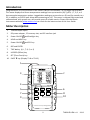
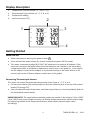
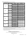
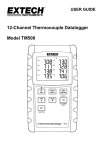
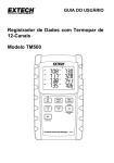
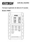
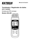
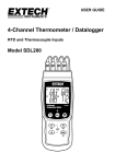
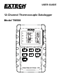
USER GUIDE 12-Channel Thermocouple Datalogger Model TM500 Introduction Congratulations on your purchase of the Extech TM500 Thermometer, an SD Logger Series meter. This meter displays and stores temperature readings from up to twelve (12) Type K, J, T, R, E, or S thermocouple temperature probes. Logged data readings are stored on an SD card for transfer to a PC. In addition, an RS232 port allows data streaming to a PC. This meter is shipped fully tested and calibrated and, with proper use, will provide years of reliable service. Please visit the Extech Instruments website (www.extech.com) to check for the latest version of this User Guide. Meter Description 1. Thermocouple inputs 2. DC power adapter , SD memory slot, and PC interface jack 3. Power ON‐OFF and Backlight key 4. HOLD and NEXT key 5. Power ON‐OFF and ESC key 6. REC and ENTER 7. TYPE ▲ key (K, J, T, R, E, or S) 8. LOGGER (Offset) key 9. SET (Time Check) key 10. PAGE ▼ key (Display T1‐8 or T9‐12) 1 K 3 CH1 CH5 CH2 CH6 CH3 CH7 CH4 CH8 2 F 4 5 7 ESC HOLD NEXT REC ENTER TYPE PAGE LOG VIEW SAMPLE 9 6 OFFSET RATE SET 8 10 VIEW TIME 12-Channel Thermocouple DataloggerTM500 2 TM500-EU-EN v1.1 12/13 Display Description 1. 2. 3. 4. Temperature Channel number (1 – 8 or 9 – 12) Thermocouple Type indicator (K, J, T, E, R, or S) Temperature reading Units of measure (C/F) 2 1 K CH1 CH5 CH2 CH6 CH3 CH7 CH4 CH8 3 F 4 Getting Started Power ON‐OFF Power the meter by pressing the power button . Press and hold the power button for at least 3 seconds to power OFF the meter. This meter is powered by eight (8) 1.5VDC ‘AA’ batteries or by optional AC adaptor. If the meter will not switch ON please check that fresh batteries are installed in the rear battery compartment (refer to the battery replacement section later in this guide) or, in the case of the AC adaptor, check that the adaptor is connected correctly to the meter and to an AC source (refer to the AC Power Adaptor section later in this guide). Connecting Thermocouple Sensors This meter can accept Thermocouple temperature probe Types K, J, T, E, R, or S. Connect up to twelve (12) thermocouples to the sub‐miniature jacks at the top of the meter labeled T1 through T12. Select the desired mode of operation, and other setup features, in the Setup Mode. Refer to the Setup Mode section below. IMPORTANT NOTE: The supplied thermocouple probes are useable in the range of ‐20 to +250°C (‐4 to +482°F) only; even though the meter can display temperature values outside of this range. For measuring outside of the range specified here, please obtain thermocouples rated accordingly. 3 TM500-EU-EN v1.1 12/13 Setup Mode Basic settings at a glance To view the current configuration of the meter with regard to time, date, and datalogging sampling rate press the SET button for > 4 seconds. The meter will now display the configuration menu. The Setup page reverts to the temperature window in approximately 8 seconds if there are no button presses. Accessing the Setup mode 1. 2. 3. 4. 5. Press and hold the SET button for at least 4 seconds to access the Setup menu. Press the NEXT button momentarily to step through the available parameters. When a parameter that is to be changed is flashing click ENTER to enter the change mode. Use the arrow keys to choose the setting and press the ENTER button to make the change. Note that the meter automatically switches out of the Setup mode if no key is pressed within 8 seconds. The available Setup parameters are listed below. Additional detailed information is provided below this list: dAtE Set the clock (Year/Month/Date; Hours/Minutes/Seconds) LooP Start and End a loop measurement cycle dEC Set the numerical format; USA (decimal: 20.00) or European (comma: 20,00) PoFF Automatic power‐off (Enable or disable the auto‐power off function) bEEP Set the beeper sound ON/OFF t‐CF Select the temperature unit of measure (C or F) SP‐t Set the datalogger sampling rate (1 to 3600 seconds) Sd F Format the SD memory card Setting the Clock Time 1. Access the dAtE parameter. 2. Press the ENTER button. 3. Use the arrow buttons to change the YEAR value. Press ENTER to confirm setting. 4. Repeat for MONTH, DAY, HOUR, MINUTE and SECONDS. 5. Press the ENTER button to exit to the Setup mode. Press ESC to exit setup mode. Note: The clock will keep accurate time even when the meter is switched off. However, if the batteries expire the clock will have to be reset after fresh batteries are installed. 4 TM500-EU-EN v1.1 12/13 Setting datalogging Loop mode This meter can be set to record temperatures for the same time every day. Example – record temperatures every day from 9:00 to 13:00 1. 2. 3. 4. 5. 6. 7. 8. Access the LooP parameter. Press the ENTER button. Set the Start Hour (0‐23) and press ENTER. Set the Start Minute and press ENTER. Set the Stop Hour and press ENTER. Set the Stop Minute and press ENTER. Press the up or down arrow to indicate YES and press ENTER. Press the REC button so the REC icon is visible on the display. The meter is now set up to record temperature every day for the set time window. Setting dEC mode ‐ Numerical Format (comma or decimal) European and USA numerical formats differ. The meter defaults to USA mode where a decimal point is used to separate units from tenths, i.e. 20.00; The European format uses a comma, i.e. 20,00 to separate units from tenths. To change this setting: 1. Access the dEC parameter. 2. Use the arrow buttons to select USA or EUro. Press ENTER to confirm setting. 3. Press the ENTER button to exit to the Setup mode. Press ESC to exit setup mode. Setting Poff ‐ Enabling/Disabling the Auto Power OFF Feature 1. 2. 3. 4. Access the PoFF parameter. Use the arrow buttons to select ON (enable) or OFF (disable). With the Auto Power OFF feature enabled, the meter will automatically switch OFF after 10 minutes of inactivity. Press ENTER to confirm setting. Press the ENTER button to exit to the Setup mode. Press ESC to exit setup mode. Set the Beeper Sound ON or OFF 1. 2. 3. Access the bEEP parameter. Use the arrow buttons to select ON or OFF. Press ENTER to confirm setting. Press the ENTER button to exit to the Setup mode. Press ESC to exit setup mode. 5 TM500-EU-EN v1.1 12/13 Set the Temperature Units of Measure (°C or °F) 1. 2. 3. Access the t‐CF parameter. Use the arrow buttons to select °C or °F. Press ENTER to confirm setting. Press the ENTER button to exit to the Setup mode. Press ESC to exit setup mode. Setting the Datalogger Sampling Time (Rate) 1. 2. 3. 4. Access the SP‐t parameter. Use the arrow buttons to select the desired sampling rate. The available settings are: 0, 1, 2, 5, 10, 30, 60, 120, 300, 600, 1800, and 3600 seconds. Use ‘0’ for manual logging mode. A sampling rate > 1 second is recommended. Press the ENTER button to confirm the entry. Press the ENTER button to exit to the Setup mode. Press ESC to exit setup mode. SD Card FORMATTING 1. 2. 3. 4. 5. Access the Sd F parameter. Use the arrow buttons to select YES to format the card (select NO to abort). Note that all data on the card will be lost if formatting is attempted. Press ENTER to confirm selection. Press ENTER again to re‐confirm. Press the ENTER button to exit to the Setup mode. Press ESC to exit setup mode. Note: always format a new SD memory card before use. 6 TM500-EU-EN v1.1 12/13 Measurements and related features Basic Thermocouple Mode Thermocouples are connected at the top of the meter to the jacks labeled T1 through T12. Select the thermocouple type (J, K, etc.) to match the thermocouple type used. In normal thermocouple mode the meter will simultaneously display the temperature for thermocouples T1 through T12. Dashes are displayed if a thermocouple is not connected or if the measurement is out of range. Data Hold To freeze a measurement on the display, press the HOLD button momentarily. The meter will emit a beep, the reading will hold, and the HOLD icon will switch on. Press the HOLD button again to release the display and exit the Data Hold mode returning the meter to the normal operating mode. Temperature Display OFFSET The VPC300 allows the user to set a display offset that applies to all of the thermocouple displays equally. To set the display offset follow the steps below: 1. Press and hold the OFFSET button for 3 seconds to reach the offset screen. The temperature on the left is the currently displayed temperature for Channel 1 and the temperature on the right is the offset temperature 2. Use the up and down arrow keys to adjust the display on the right to offset the display as desired. 3. When finished, press the ENTER button to store the offset and return to normal operation. 4. All of the thermocouple readings will now reflect the offset value programmed by the user. To clear the OFFSET, follow the steps below: 1. Switch the meter power OFF 2. Press and hold the HOLD and REC buttons while switching the meter power ON 3. Release the two buttons when the meter switches ON 4. Press and hold the OFFSET button for 5 seconds and the display will show CODE 100 5. Use the up arrow button to change from CODE 100 to CODE 125 and then press ENTER 6. Use the arrow buttons to select YES or NO and then press ENTER 7. If YES is selected, the meter will clear the previously programmed offset. If NO is selected, the meter will retain the offset programmed by the user. MAX‐MIN Readings For a given measurement session, this meter can record the highest (MAX) and the lowest (MIN) readings for later recall. 1. Press the REC button momentarily to access this mode of operation (REC icon appears) 2. The meter is now recording the MAX and MIN readings. 3. Press the REC button again to view the current MAX readings (MAX icon appears). The readings on the display are now the highest readings encountered since the REC icon was 7 TM500-EU-EN v1.1 12/13 4. 5. switched on (when the MAX‐MIN button was first pressed). To delete the MAX value, press the HOLD button. The display will show just the REC icon. Press the REC button again to view the current MIN readings (MIN icon appears). The readings on the display are now the lowest readings encountered since the REC icon was switched on (when the MAX‐MIN button was first pressed). To delete the MIN value, press the HOLD button. The display will show just the REC icon. To exit the MAX‐MIN mode, press and hold the REC button for at least 1.5 seconds. The meter will beep, the REC‐MAX‐MIN icons will switch off, the MAX‐MIN memory will clear, and the meter will return to the normal operating mode. Display Backlight To turn the display backlight ON or OFF, press the backlight button momentarily. The meter will beep when switching the backlight ON or OFF unless the beeper is disabled as described in the Setup Mode section of this user guide. Time Check Momentarily press the SET button and the meters current Date and Time will appear in the lower left corner of the display. Sampling Time Check When in normal mode, press the LOGGER button momentarily. The Sample rate setting will appear in the lower left corner of the display. RS‐232/USB PC Interface For streaming of data to a PC via the RS232 Output jack, the optional 407001‐USB kit (USB cable and driver CD) along with the 407001 software (available free at www.extech.com) are required. AC Power Adaptor This meter is normally powered by eight (8) 1.5V ‘AA’ batteries. An optional 9V power adaptor is available. When the adaptor is used, the meter is permanently powered and the power button will be disabled. 8 TM500-EU-EN v1.1 12/13 Datalogging and PC Interface Types of Data Recording Manual Datalogging: Manually log up to 99 readings onto an SD card via push‐button press. The sample rate must be set to 0 to implement this mode. Automatic Datalogging: Automatically log data onto an SD memory card where the number of data points is virtually limited only by the card size. Readings are logged at a rate specified by the user from 1 to 3600 seconds. RS‐232/USB: The meter includes an RS‐232/USB PC interface jack located on the lower right side of the meter under the snap‐off compartment cover. For streaming of data to a PC via the RS232 Output jack, the optional 407001‐USB kit (USB cable and driver CD) along with the 407001 software (available free at http://www.extech.com/instruments/software.asp) are required. SD Card Information Insert an SD card (from 1G size up to 16G) into the SD card slot at the bottom of the meter. The card must be inserted with the front of the card (label side) facing toward the rear of the meter. If the SD card is being used for the first time it is recommended that the card be formatted and the logger’s clock set to allow for accurate date/time stamping during datalogging sessions. Refer to the Setup Mode section for SD card formatting and time/date setting instructions. European and USA numerical formats differ. The data on the SD card can be formatted for either format. The meter defaults to USA mode where a decimal point is used to separate units from tenths, i.e. 20.00. The European format uses a comma, i.e. 20,00. To change this setting, refer to the Setup Mode section. Manual Datalogging In the manual mode the user presses the LOG button to manually log a reading onto the SD card. 1. Set the sampling rate to ‘0’ seconds as described in the Setup Mode section. 2. Press REC button to turn on manual record mode. The REC icon will appear in the upper left corner of the display. The lower portion of the display will show p‐n (n = memory position number 1‐99). 3. Press the ENTER button momentarily to log a reading into memory. The LOGGER icon will flash each time a data point is stored (the SCAN SD icon will appear when the meter accesses the card). 4. Advance to the next memory location using the up arrow ▲ button. 5. To exit the manual datalogging mode, press and hold the REC button for at least 1.5 seconds. 9 TM500-EU-EN v1.1 12/13 Automatic Datalogging In automatic datalogging mode the meter takes and stores a reading at a user‐specified sampling rate onto an SD memory card. The meter defaults to a sampling rate of two seconds. To change the sampling rate, refer to the Setup Mode section (the sampling rate cannot be ‘0’ for automatic datalogging): 1. Press REC button to turn on record mode. The REC icon will appear in the upper left corner of the display. 2. Start an automatic Datalogging session by pressing the LOGGER button. 3. The meter will scan for an SD card and verify that it can be used to store data. If a card is not inserted or if the card is defective, the meter will display SCAN SD indefinitely. In this case, switch the meter OFF and try again with a valid SD card. 4. If the SD card is valid, the display will show the DATALOGGER icon and then the DATALOGGER and the REC icons will flash each time that a reading is stored. 5. To pause the datalogger press the LOGGER button momentarily. The DATALOGGER and REC icons will stop flashing. To resume logging simply press the LOGGER button again momentarily. 6. To terminate the datalogging session press the LOGGER button to stop the logging and then press the REC button for at least 1.5 seconds. 7. When an SD card is used for the first time a folder is created on the card and named TMD01. Up to 99 spreadsheet documents (each with 30,000 readings) can be stored in this folder. 8. When datalogging begins a new spreadsheet document named TMD01001.xls is created on the SD card in the TMD01 folder. The data recorded will be placed in the TMD01001.xls document until 30,000 readings are reached. 9. If the measurement session exceeds 30,000 readings, a new document will be created (TMD01002.xls) where another 30,000 readings can be stored. This method continues for up to 99 documents, after which another folder is created (TMD02) where another 99 spreadsheet documents can be stored. This process continues in this same fashion with folders TMD03 through TMD10 (last allowable folder). 10 TM500-EU-EN v1.1 12/13 SD Data Card to PC Data Transfer 1. 2. 3. 4. Complete a datalogging session as detailed in above in the previous sections. Hint: For the first test, simply record a small amount of test data. This is to ensure that the datalogging process is well understood before committing to critical datalogging. With the meter switched OFF, remove the SD Card. Plug the SD Card directly into a PC SD card reader. If the PC does not have an SD card slot, use an SD card adaptor (available at most outlets where computer accessories are sold). Power the PC and run a spreadsheet software program. Open the saved documents in the spreadsheet software program (see example spreadsheet data screens below). Spreadsheet data example Spreadsheet example (Plotting the data) 11 TM500-EU-EN v1.1 12/13 Battery Replacement and Disposal When the low battery icon appears on the LCD, the batteries must be replaced. Several hours of accurate readings are still possible in this condition; however batteries should be replaced as soon as possible: Remove the two (2) Phillips screws from the rear of the meter. Remove and safely place the battery compartment and screws where they will not be lost. Replace the eight (8) 1.5V ‘AA’ batteries observing polarity. Replace the battery compartment cover with the two (2) Phillips screws. Battery Safety Reminders Never dispose of batteries in a fire. Batteries may explode or leak. Never mix battery types. Always install new batteries of the same type. As consumers, users are legally required to take used batteries to appropriate collection sites, the retail store where the batteries were purchased, or wherever batteries are sold. Disposal: Do not dispose of this instrument in household waste. The user is obligated to take end‐of‐life devices to a designated collection point for the disposal of electrical and electronic equipment. 12 TM500-EU-EN v1.1 12/13 Specifications General Specifications Display Backlit LCD; LCD size: 82×61mm (3.23×2.40") Status indicators Over‐range (‐‐‐‐) and low battery Measurement Channels T1 to T12 Sensor types Thermocouple types: K, J, T, E, R, and S Measurement Units °C / °F Offset Adjustment To adjust the zero temperature deviation value Linearity Compensation Linear compensation for the full range Datalogger Sampling Rate AUTO LOGGING: 1, 2, 5, 10, 30, 60, 120, 300, 600, 1800, 3600 seconds. Note that a one (1) second sampling rate can cause some data loss on slower computers Memory Card SD memory card; 1G to 16GB size Temperature Compensation Automatic compensation for all thermocouple types Display update rate Approx. 1 second. Data Output RS‐232 / USB PC computer interface (9600, N, 8, 1) Operating Temperature 0 to 50°C (32 to 122°F) Operating Humidity 85% R.H. maximum Auto Power OFF After 10 minutes of inactivity (can be disabled) Power Supply Eight (8) 1.5 VDC batteries (optional 9V AC adaptor) Power Consumption With backlight & datalogger OFF: approx. 7.5mA dc With backlight OFF and datalogger ON: approx. 25mA dc With backlight ON and datalogger ON: approx. 36mA dc Weight 827g (1.84 lbs.) meter only Dimensions Main instrument: 225 x 125 x 64mm (8.86 x 4.92 x 2.52”) 13 TM500-EU-EN v1.1 12/13 Thermocouple Input (types K, J, T, E, R, and S) Sensor Type Resolution 0.1°C Type K 1°C 0.1°F 1°F 0.1°C Type J 1°C 0.1°F 1°F 0.1°C Type T 0.1°F 0.1°C Type E 0.1°F 1°F 1°C Type R 1°F 1°C Type S 1°F Range ‐100.0 to ‐50.1°C ‐50.0 to 999.9°C 1000 to 1300°C ‐148.0 to ‐58.1°F ‐58.0 to 999.9°F 1000 to 2372°F ‐100.0 to ‐50.1°C ‐50.0 to 999.9°C 1000 to 1150°C ‐148.0 to ‐58.1°F ‐58.0 to 999.9°F 1000 to 2102°F ‐100.0 to ‐50.1°C ‐50.0 to 400.0°C ‐148.0 to ‐58.1°F ‐58.0 to 752.0°F ‐100.0 to ‐50.1°C ‐50.0 to 900.0°C ‐148.0 to ‐58.1°F ‐58.0 to 999.9°F 1000 to 1652°F 0 to 600°C 601 to 1700°C 32 to 1112°F 1113 to 3092°F 0 to 600°C 601 to 1500°C 32 to 1112°F 1113to 2732°F Accuracy ±(0.4 % + 1°C) ±(0.4 % + 0.5°C) ±(0.4 % + 1°C) ±(0.4 % + 1.8°F) ±(0.4 % + 1°F) ±(0.4 % + 2°F) ±(0.4 % + 1°C) ±(0.4 % + 0.5°C) ±(0.4 % + 1°C) ±(0.4 % + 1.8°F) ±(0.4 % + 1°F) ±(0.4 % + 2°F) ±(0.4 % + 1°C) ±(0.4 % + 0.5°C) ±(0.4 % + 1.8°F) ±(0.4 % + 1°F) ±(0.4 % + 1°C) ±(0.4 % + 0.5°C) ±(0.4 % + 1.8°F) ±(0.4 % + 1°F) ±(0.4 % + 2°F) ±(0.5 % + 3°C) ±(0.5 % + 5°F) ±(0.5 % + 3°C) ±(0.5 % + 5°F) The supplied thermocouple probes are useable in the range of ‐20 to +250°C (‐4 to +482°F) only. For measuring outside of this range, please obtain thermocouples rated accordingly. Accuracy specified for meter only. Input probes add additional measurement error. Generally RTD probes introduce a smaller error than thermocouples. The above specifications are tested under an environmental RF Field Strength lower than 3 V/M and a frequency lower than 30 MHz Copyright © 2013 FLIR Systems, Inc. All rights reserved including the right of reproduction in whole or in part in any form www.extech.com 14 TM500-EU-EN v1.1 12/13