1
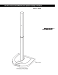
The Bose® Personalized Amplification System™ Family of Products
Owner’s Guide
www.bose.com/musicians
Safety Information
WARNING: To reduce the risk of fire or electrical shock, do not expose the system to rain or
moisture.
CAUTION: To prevent electric shock, match the wide blade of the line cord plug to the wide slot
of the AC (mains) receptacle.
CA
AUTION
UTION
AVI
VI S
RISK OF ELECTRICAL SHOCK
DO NOT OPEN
RISQUE DE CHOC ÉLECTRIQUE
NE PAS OUVRIR
CAUTION: TO REDUCE THE RISK OF ELECTRIC SHOCK,
DO NOT REMOVE COVER (OR BACK).
NO USER-SERVICABLE PARTS INSIDE.
REFER SERVICING TO QUALIFIED PERSONNEL.
ATTENTION : POUR RÉDUIRE LE RISQUE DE DÉCHARGE
ÉLECTRIQUE, NE RETIREZ PAS LE COUVERCLE (OU
L’ARRIÈRE). IL NE SE TROUVE ÀL’INTÉRIEURAUCUNE
PIÈCE POUVANT ÊTRE RÉPARÉE PARL’USAGER.
S’ADRESSER À UN RÉPARATEUR COMPÉTENT.
CAUTION: To reduce the risk of electric shock, do not disassemble this system unless you are
qualified. Refer servicing to qualified service personnel. The CAUTION marks shown here are
located on the enclosures of your system.
These CAUTION marks may be located on the enclosures of the Personalized Amplification System™ PS1 power stand:
The lightning flash with arrowhead symbol within an equilateral triangle alerts the
user to the presence of uninsulated dangerous voltage within the system enclosure
that may be of sufficient magnitude to constitute a risk of electrical shock.
The exclamation point within an equilateral triangle, as marked on the system, is
intended to alert the user to the presence of important operating and maintenance
instructions in this owner’s guide.
Additional safety information
See the additional safety information on the Important Safety Instructions sheet enclosed with
your system.
Please read this owner’s guide
Please take the time to follow the instructions in this owner’s guide carefully. It will help you
set up and operate your system properly and enjoy all of its advanced features. Please save
this owner’s guide for future reference.
CAUTION: No naked flame sources, such as lighted candles, should be placed on the
apparatus.
CAUTION: Where the mains plug is used as the disconnect device, such disconnect device
shall remain readily operable.
©2003 Bose Corporation. No part of this work may be reproduced, modified, distributed or otherwise
used without prior written permission.
2
Important Safety Instructions
1. Read these instructions.
2. Keep these instructions.
3. Heed all warnings.
4. Follow all instructions.
5. Do not use this apparatus near water.
6. Clean only with a dry cloth.
7. Do not block any ventilation openings. Install in
accordance with the manufacturer’s instructions.
8. Do not install near any heat sources, such as
radiators, heat registers, stoves or other apparatus (including amplifiers) that produce heat.
9. Do not defeat the safety purpose of the polarized or grounding-type plug. A polarized plug
has two blades with one wider than the other. A
grounding-type plug has two blades and a third
grounding prong. The wider blade or third prong
are provided for your safety. If the provided plug
does not fit into your outlet, consult an electrician for replacement of the obsolete outlet.
10. Protect the power cord from being walked on or
pinched, particularly at plugs, convenience
receptacles, and the point where they exit from
the apparatus.
11. Only use attachments/accessories specified by
the manufacturer.
12. Use only with the cart, stand, tripod,
bracket or table specified by the manufacturer or sold with the apparatus.
When a cart is used, use caution when
moving the cart/apparatus combination to avoid
injury from tip-over.
13. Unplug this apparatus during lightning storms
or when unused for long periods of time.
14. Refer all servicing to qualified service personnel.
Servicing is required when the apparatus has
been damaged in any way, such as power-supply
cord or plug is damaged, liquid has been spilled
or objects have fallen into the apparatus, the
apparatus has been exposed to rain or moisture,
does not operate normally, or has been dropped.
Information about products that
generate electrical noise
This equipment has been tested and found to comply with the limits for a Class A digital device, pursuant to Part 15 of the FCC rules. These limits are
designed to provide reasonable protection against
harmful interference in a commercial environment.
This equipment generates, uses, and can radiate
radio frequency energy and, if not installed and used
in accordance with the instructions, may cause
harmful interference to radio communications. Operation of this equipment in a residential area is likely
to cause harmful interference in which case the user
will be required to correct the interference at his own
expense.
This product complies with the Canadian ICES-003
Class A specifications.
15. To prevent risk of fire or electric shock, avoid
overloading wall outlets, extension cords, or
integral convenience receptacles.
16. Do not let objects or liquids enter the product –
as they may touch dangerous voltage points or shortout parts that could result in a fire or electric shock.
17. See product enclosure bottom for safety related
markings.
18. Use Proper Power Sources – Plug the product into
a proper power source, as described in the operating
instructions or as marked on the product.
3
Important Safety Instructions
19. Avoid Power Lines – Use extreme care when installing an outside antenna system to keep from touching
power lines or circuits, as contact with them may be
fatal. Do not install external antennas near overhead
power lines or other electric light or power circuits, nor
where an antenna can fall into such circuits or power
lines.
20. Ground All Outdoor Antennas – If an external
antenna or cable system is connected to this product,
be sure the antenna or cable system is grounded. This
will provide some protection against voltage surges
and built-up static charges.
Section 810 of the National Electrical Code ANSI/
NFPA No. 70 provides informaiton with respect to
proper grounding of the mast and supporting structure, grounding of the lead-in wire to an antenna discharge unit, size of grounding conductors, location of
antenna-discharge unit, connection to grounding electrodes, and requirements for the ground electrode.
Refer to the antenna grounding illustration on this
page.
Antenna grounding
Example of antenna grounding as per National Electrical
Code, ANSI/NFPA 70.
Antenna lead-in wire
Ground clamp
Electric service
equipment
Antenna discharge unit
(NEC Section 810-20)
Grounding conductors
(NEC Section 810-21)
Ground clamps
Power service grounding electrode
system (NEC ART 250, Part H)
Note to CATV system installer
This reminder is provided to call the CATV system
installer’s attention to Article 820-40 of the NEC (of USA)
that provides guidelines for proper grounding. In particular,
it specifies that the cable ground shall be connected to the
grounding system of the building, as close to the point of
cable entry as is practical.
4
Contents
Where to find...
Setup . . . . . . . . . . . . . . . . . . . . . . . . . . . . . . . . . . . . . . . . . . . . . . . . . . . . . . . . . . . . . . . . . . . . . . . .
Before you begin . . . . . . . . . . . . . . . . . . . . . . . . . . . . . . . . . . . . . . . . . . . . . . . . . . . . . . . . . . .
Unpacking . . . . . . . . . . . . . . . . . . . . . . . . . . . . . . . . . . . . . . . . . . . . . . . . . . . . . . . . . . . . . . . .
Placing the product in the right location for your performance . . . . . . . . . . . . . . . . . . . . . . . .
Product assembly . . . . . . . . . . . . . . . . . . . . . . . . . . . . . . . . . . . . . . . . . . . . . . . . . . . . . . . . . . .
Disassembly . . . . . . . . . . . . . . . . . . . . . . . . . . . . . . . . . . . . . . . . . . . . . . . . . . . . . . . . . . . . . . .
Connecting a bass module to the power stand (optional) . . . . . . . . . . . . . . . . . . . . . . . . . . . .
Connecting one bass module . . . . . . . . . . . . . . . . . . . . . . . . . . . . . . . . . . . . . . . . . . . . . .
Connecting two bass modules . . . . . . . . . . . . . . . . . . . . . . . . . . . . . . . . . . . . . . . . . . . . .
Setting up additional power stands for more bass output . . . . . . . . . . . . . . . . . . . . . . . . . . . .
Full bass setup . . . . . . . . . . . . . . . . . . . . . . . . . . . . . . . . . . . . . . . . . . . . . . . . . . . . . . . . . .
Distributed bass setup . . . . . . . . . . . . . . . . . . . . . . . . . . . . . . . . . . . . . . . . . . . . . . . . . . . .
Shared bass setup . . . . . . . . . . . . . . . . . . . . . . . . . . . . . . . . . . . . . . . . . . . . . . . . . . . . . . .
6
6
7
8
9
10
11
11
12
13
13
14
15
Controls, Indicators and Connections . . . . . . . . . . . . . . . . . . . . . . . . . . . . . . . . . . . . . . . . . . . . . .
Channel 1/2 connections and controls . . . . . . . . . . . . . . . . . . . . . . . . . . . . . . . . . . . . . . . . . . .
Channel 3/4 connections and controls . . . . . . . . . . . . . . . . . . . . . . . . . . . . . . . . . . . . . . . . . . .
Power amp patch, bass, remote and AC power connections . . . . . . . . . . . . . . . . . . . . . . . . .
Remote control features . . . . . . . . . . . . . . . . . . . . . . . . . . . . . . . . . . . . . . . . . . . . . . . . . . . . . .
16
16
16
17
18
Operating Instructions . . . . . . . . . . . . . . . . . . . . . . . . . . . . . . . . . . . . . . . . . . . . . . . . . . . . . . . . . .
Producing individualized sound . . . . . . . . . . . . . . . . . . . . . . . . . . . . . . . . . . . . . . . . . . . . . . . .
Using input channels 3 and 4 . . . . . . . . . . . . . . . . . . . . . . . . . . . . . . . . . . . . . . . . . . . . . . . . . .
Using an effects processor . . . . . . . . . . . . . . . . . . . . . . . . . . . . . . . . . . . . . . . . . . . . . . . . . . . .
19
19
19
20
Maintaining Your Product . . . . . . . . . . . . . . . . . . . . . . . . . . . . . . . . . . . . . . . . . . . . . . . . . . . . . . . .
Troubleshooting . . . . . . . . . . . . . . . . . . . . . . . . . . . . . . . . . . . . . . . . . . . . . . . . . . . . . . . . . . . .
Customer Service . . . . . . . . . . . . . . . . . . . . . . . . . . . . . . . . . . . . . . . . . . . . . . . . . . . . . . . . . . .
Cleaning your product . . . . . . . . . . . . . . . . . . . . . . . . . . . . . . . . . . . . . . . . . . . . . . . . . . . . . . .
Warranty . . . . . . . . . . . . . . . . . . . . . . . . . . . . . . . . . . . . . . . . . . . . . . . . . . . . . . . . . . . . . . . . . .
Accessories . . . . . . . . . . . . . . . . . . . . . . . . . . . . . . . . . . . . . . . . . . . . . . . . . . . . . . . . . . . . . . .
21
21
22
22
22
22
Technical Information . . . . . . . . . . . . . . . . . . . . . . . . . . . . . . . . . . . . . . . . . . . . . . . . . . . . . . . . . . .
23
For your records
The product serial number is located on the bottom of the power stand.
Serial number: ________________________________________________________________
Dealer Name: _________________________________________________________________
Dealer phone: ____________________________ Purchase date: _____________________
Please keep your sales receipt and product registration card together with this owner’s
guide.
5
Setup
Before you begin
Thank you for purchasing one of the Bose® Personalized Amplification System™ family of
products. This new revolutionary technology brings the benefits of the intimate acoustic concert to amplified performances.
Benefits for musicians
• You control the sound - Just as in an unamplified performance, you, and no one else,
control the sound. You will no longer wonder how you sound to your fellow musicians or to
your audience.
• Quick and easy setup - The Personalized Amplification System™ product is carried and
set up in minutes, not hours. This frees you from the time-consuming, draining, and frustrating effort required to properly set up conventional sound equipment.
• Dramatically improved performance - Performance and enjoyment dramatically
improve because you will no longer struggle to hear yourself and the other musicians.
Benefits for the audience
• Creates excitement and emotion - The enhanced performance of the musicians creates the kind of excitement and emotion that is valued by music lovers more than anything
else.
• You hear what the audience hears - For the first time, musicians hear what their audiences hear and thus, are unlikely to play at uncomfortable sound levels.
• The music is naturally dynamic - The softest to the more intense passages can be
heard and enjoyed.
• You look better - There is less clutter on the stage and more room.
• Sound reproduction unlike before - Audience members report that the clarity and
excitement that come from hearing the accurate reproduction of sound from each instrument, and from hearing the sound of each instrument in its position on stage (as opposed
to mono or even stereo mix of all instruments) is unlike anything they have heard before in
an amplified performance.
For more information
This owner’s guide provides only basic setup and operating instructions. For more in-depth
information on using this system, please vist www.bose.com/musicians on the Internet.
6
Setup
Unpacking
Your Personalized Amplification System™ product (Figure 1) is delivered to you in two cartons. One carton contains the power stand, power stand AC line cord, remote control, and
remote control cable. The other carton contains the Cylindrical Radiator™ loudspeaker.
If you purchased the optional Model B1 bass module or the carrying bag for the Model L1
Cylindrical Radiator loudspeaker (Figure 2), they are packaged separately.
Figure 1
Top
section
System components
Model R1 remote
control
Model PS1 power stand
Power cord
Bottom
section
Remote control
cable (15 ft) (4.6 m)
Model L1 Cylindrical Radiator
loudspeaker
Figure 2
Optional equipment and
accessories
Model B1 bass module
MB1 bass module
4-wire cable
(5 ft) (1.5 m)
Carrying bag
for the
Model L1 Cylindrical Radiator
loudspeaker
7
Setup
Placing the product in the right location for your performance
Before you start to assemble this product, it is a good idea to find the best location for it.
CAUTION: The completed unit weighs about 60 lb. Moving the completely assembed unit is not
recommended.
Placing the power stand in the right location is an important step in the process of setting up
this product to create your own individualized sound. Determining the best location for your
performance depends on several things: size of staging area, number of performers, if you
will be sharing the power stand connections.
The following guidelines should get you started in setting up for a concert or show. For more
information on setting up your Personalized Amplification System™ product to achieve an
individualized sound, visit www.bose.com/musicians on the internet.
• Place the product at the rearmost part of the performance area or stage.
• If possible, position the product behind the performer.
• If you are part of a group, avoid crowding together on stage. Allow some distance (ideally
7-8 feet) between you and the line array and another performer. This allows the sound to
wrap around performers and reflect off adjacent surfaces of the room, creating a more
pleasing room-filling “wide-screen” sound.
Figure 3
Wall
Placement
recommendations
OK
3 ft
3 ft
3 ft
3 ft
3 ft
Drummer
Keyboard
Bass
Wall
Better
5 ft
5 ft
5 ft
5 ft
5 ft
Drummer
Keyboard
Bass
Wall
Best
7-8 ft
7-8 ft
7-8 ft
Keyboard
8
Drummer
7-8 ft
7-8 ft
Bass
Setup
Product assembly
1. Place the power stand on the floor. Place it on a
flat, dry, stable surface at the rearmost part of the stage,
handle facing forward, behind the performer.
4. Connect the remote control to the power stand.
Plug the remote control cable into either end of the
remote. Plug the other end into the Remote jack.
CAUTION: The completed unit
weighs about 60 lb. Moving the
completely assembed unit is not recommended.
For placement guidelines, see “Placing the
product in the right location for your performance” on page 8.
2. Insert the bottom section of the
Cylindrical Radiator™ loudspeaker
into the power stand. You should
hear a soft click when it is properly
seated and locked in place.
Note: Electrical connections between
the power stand and loudspeaker are
made automatically as you assemble the
product.
5. Place the remote control within reach of your
performance position. This will allow you to both hear
your performance and to control it directly.
6. Plug in the power stand and turn it on. Plug the
female end of the power cord into the AC Mains jack on
the power stand. Plug the other end into an AC (mains)
receptacle.
3. Mount the top section of the Cylindrical Radiator
loudspeaker. Place one foot on the power stand to
support your back. Insert the bayonet on the top section
into the channel that runs along the
back of the bottom section. Lower
the top section until it is flush with
the top of the bottom section. You
should hear a soft click as the top
section locks in place.
Your Personalized Amplification System™
product is now set up and ready for the
addition of other equipment.
• See “Connecting a bass module to the power
stand (optional)” on page 11.
• See “Using an effects processor” on page 20.
9
Setup
Disassembly
CAUTION: Before disassembly, turn the power off and then remove the AC power cord and all
other cables from the power stand.
Remove the top loudspeaker section
Place one foot on the power stand to support your
back. Firmly grasp the top section with one hand.
Using your other hand, press the release button with
your thumb and remove the top section
from bottom section.
Remove the bottom loudspeaker section
Using your foot, push down on the power stand
treadle and lift the bottom loudspeaker section
up and out of the power stand.
10
Setup
Connecting a bass module to the power stand (optional)
The Bass/Amp 3 OUT jack on the power stand can adequately drive one or two Model B1
bass modules. Bass modules can be placed on the floor vertically or horizontally. Up to four
modules may be stacked when placed horizontally (Figure 4).
CAUTION: Do not connect more than two Model B1 bass modules to the Bass/Amp 3 OUT
connector on the power stand. Driving more than two bass modules from the Bass/Amp 3 OUT
output will improperly load the amplifier in the power stand resulting in less than full system
performance.
Figure 4
Recommended bass
module orientations
Bass modules can be placed
vertically or horizontally
Modules may be stacked in a column
of up to four, maximum
Connecting one bass module
Insert one end of the bass module 4-wire cable into one of the jacks on the rear panel of the
bass module. Insert the other end of the 4-wire cable into the Bass/Amp 3 OUT jack on the
power stand connector panel.
Figure 5
Installation of one
bass loudspeaker
To connect, push the plug into the
jack and rotate it clockwise to lock
it (you will hear a soft click).
To
Bass/Amp 3 OUT
To disconnect, slide back the metal
tab on the body of the plug, rotate the
plug counterclockwise and pull it out
of the jack.
4-wire cable
11
Setup
Connecting two bass modules
Connect the first bass module to the power stand as shown in “Connecting one bass module” on page 11.
Insert one end of the second bass module cable into the unused jack on the rear panel of the
first bass module. Insert the other end of the cable into one of the jacks on the rear panel of
the second bass module.
CAUTION: Do not connect more than two Model B1 bass modules to the Bass/Amp 3 OUT
connector on the power stand. Driving more than two bass modules from the Bass/Amp 3 OUT
output will improperly load the amplifier in the power stand resulting in less than full system
performance.
Note: Use only the supplied 4-wire speaker cable to connect bass modules to the power stand.
The power stand uses the signals on two of the four wires to automatically sense how many bass
modules are connected to it. DO NOT SUBSTITUTE the supplied cable with a 2-wire speaker
cable.
Figure 6
Installation of two bass
modules
To
Bass/Amp 3 OUT
12
Setup
Setting up additional power stands for more bass output
If you need more bass output than a single power stand with two bass modules can deliver,
there is a solution. You can purchase an additional power stand (without loudspeakers) and
use its three amplifier channels to drive up to six more bass modules. The second power
stand operates as a slave to your primary power stand.
There are three bass configurations:
• Full bass
• Distributed bass
• Shared bass
Note: Do not insert a Cylindrical Radiator™ loudspeaker into a power stand when it is being
used as a stand-alone amplifier. This automatically switches the outputs of the amplifiers from the
control panel jacks (Amp 1 OUT, Amp 2 OUT, and Amp 3 OUT) to the loudspeakers.
Full bass setup
A full bass configuration (Figure 7) consists of two bass modules connected to a primary
(“master”) power stand and six bass modules connected to a “slave” power stand which is
driven by the “master” power stand. In a full bass configuration, all eight bass modules are
driven by the same level and equalization settings. Because this configuration is abnormally
bass-heavy, you may need to adjust the equalization on the remote control to suit your artistic preference.
Figure 7
Amp 1 OUT
Amp 2 OUT
All Amps IN
Bass/Amp 3 OUT
Bass Line OUT
Bass/Amp 3 OUT
Full bass block diagram
Bass modules
Primary power
stand
Slave power
stand
1.
Set up your primary power stand using two bass modules. See “Product assembly” on
page 9 and “Connecting a bass module to the power stand (optional)” on page 11.
2.
Connect all six additional bass modules to the second power stand. Connect two bass
modules to the Bass/Amp 3 OUT jack. Connect two bass modules to Amp 1 OUT and
two more to Amp 2 OUT. See “Connecting two bass modules” on page 12.
3.
Group all bass modules together. They can be stacked as shown in Figure 6.
4.
Using a typical ¼-inch phone plug connection cable (guitar cable), connect the Bass
Line OUT jack on your primary power stand to the All Amps IN jack on the second
power stand.
13
Setup
Distributed bass setup
A distributed bass configuration (Figure 8) can be created by using each of the three power
stand amplifiers individually to drive additional bass modules for different performers.
For example, let’s say you are a member of an ensemble that includes bass guitar, drums,
and a keyboard and all members have a full (optional bass module included) Personalized
Amplification System™ unit. When the ensemble plays in louder clubs or larger performance
spaces, a bigger sound is needed. The drummer wants more kick drum impact, the bass
player wants a little more level on the lower octaves, and the keyboard player needs more low
end capability for that pipe organ patch used at the end of the show. Adding a stand-alone
power stand enables you to provide separate bass for each performer in order to better preserve the localization of each instrument.
Figure 8
Bass
14
Drums
Slave power
stand
Bass Line OUT
Bass/Amp 3 OUT
Amp 2 OUT
Amp 2 IN
Amp 3 IN
Bass/Amp 3 OUT
Amp 1 IN
Amp 1 OUT
Bass/Amp 3 OUT
Bass Line OUT
Bass/Amp 3 OUT
Bass Line OUT
Distributed bass block
diagram
Keyboard
1.
Connect the Bass Line OUT of the drummer’s power stand to the Amp 1 IN on the slave
power stand. Place an additional pair of bass modules near the bass modules connected
to the drummer’s power stand and connect the Amp 1 OUT of the slave power stand to
the additional bass modules.
2.
Connect the Bass Line OUT of the bass player’s power stand to the Amp 3 IN on the
slave power stand. Place an additional pair of bass modules near the bass modules connected to the bass player’s power stand and connect the Bass/Amp 3 OUT of the slave
power stand to the additional bass modules.
3.
Connect the Bass Line OUT of the keyboard player’s power stand to the Amp 2 IN on
the slave power stand. Place an additional pair of bass modules near the bass modules
connected to the keyboard player’s power stand and connect the Amp 2 OUT of the
slave power stand to the additional bass modules.
Setup
Shared bass setup
In a shared bass configuration (Figure 9), the musicians can use all the available bass power.
Based on the previous example, a shared bass configuration could be set up for the bass
player and the drummer. This involves inputting the drums and bass to the master power
stand on channels 1 and 2 and driving a full base configuration with a second power stand.
You may want to select an appropriate preset for input channels 1 and 2, or set up an external mixer for drums if more elaborate mixing is needed.
The primary power stand would be placed somewhere between the bass player and the
drummer and the bass would sit somewhere near all this and the primary power stand’s two
bass modules.
The Cylindrical Radiator™ loudspeaker would distribute the upper harmonics of the bass and
drums. This shared configuration would use eight bass modules and be quite suitable for
very aggressive playing in night clubs and moderate concerts for up to 200 people.
Figure 9
Amp 1 OUT
Amp 2 OUT
Bass/Amp 3 OUT
All Amps IN
Ch 2 Input
Ch 1 Input
Bass Line OUT
Bass/Amp 3 OUT
Shared bass block diagram
Bass modules
Primary power
stand
Drum
mixer
Slave power
stand
Bass guitar preamp
or direct box
1.
Set up your primary power stand using two bass modules. See “Product assembly” on
page 9 and “Connecting a bass module to the power stand (optional)” on page 11.
2.
Connect all six additional bass modules to the second power stand. Connect two bass
modules each to the Amp 1 OUT, Amp 2 OUT, and Bass/Amp 3 OUT jacks. See “Connecting two bass modules” on page 12.
3.
Group the bass modules together. They can be stacked as shown in Figure 6 (page 12).
4.
Using a typical ¼-inch phone plug connection cable (guitar cable), connect the Bass
Line OUT jack on your primary power stand to the All Amps IN jack on the second
power stand.
5.
Connect the bass guitar to the Channel 1 Input jack.
6.
Connect the drum mixer to the Channel 2 Input jack.
7.
Select an appropriate preset for channels 1 and 2.
15
Controls, Indicators, and Connections
Channel 1/2 connections and controls
Unbal
Unbal
Input ..........................................Combination XLR (mic) or ¼-inch TRS (Line) input jack.
Inserting a male XLR connector sends the input signal to a
balanced microphone preamplifier. Inserting a ¼-inch phone
connector sends the input signal to an unbalanced highimpedance line-level circuit which is suitable for most instruments such as active or passive guitars or basses, keyboards, etc. Both inputs can be adjusted with the Trim
control.
Mic Trim 0 to 12 ........................Controls the microphone input level.
Signal/OL ..................................Indicates signal presence (green) or signal overload (red).
Phantom Off/+24V ....................When depressed turns on the +24V phantom power. The
LED lights when phantom power is on.
Preset Select ............................Selects a comprehensive channel equalization, which results
in a “normal” or useful sound when the product is used with
commonly available equipment such as microphones, musical instruments or sound processors. The selectable settings
from 00 to 99 apply only to channel and 2. Settings are identical on both channels but are independently selected. See
the Presets Guide included in the power stand carton.
Line OUT ...................................XLR output for sending to external recording equipment.
Insert .........................................A TRS line input/output for connecting to external equipment. Plug inserted halfway connects to “Send”; inserted
fully connects to “Return”.
Note: Use a stereo plug in the Insert jack for connecting send and return signals.
Channel 3/4 connections and controls
Line IN .......................................A ¼-inch phone connector line input for external equipment.
Level 0 to 12..............................Controls the source input level.
16
Controls, Indicators and Connections
Power amp patch, bass, remote and AC power connections
TRS Bal/Unbal
®
Commercial
Audio Product
917D
Used only when a
Cylindrical Radiator™
loudspeaker is NOT
installed in the power
stand.
Amp 1 IN....................................Amplifier 1 input jack.
Amp 2 IN....................................Amplifier 2 input jack.
Amp 3 IN....................................Amplifier 3 input jack.
All Amps IN ...............................Input jack to all amplifiers.
Amp 1 OUT................................Amplifier 1 output jack.
Amp 2 OUT................................Amplifier 2 output jack.
Bass/Amp 3 OUT ......................Bass output (amplifier 3 output) jack. Used to drive one or
two Model B1 bass modules.
Bass - Line OUT .......................Bass signal output for driving a second power stand used in
an extended bass configuration.
Data IN ......................................Digital data input. Used for updating product software.
Data OUT ..................................Channel 1/2 digital output.
Remote......................................Input connection for the remote control.
AC Mains...................................3-conductor power cord connections.
Fuse ...........................................AC power fuse.
On/Off........................................Power stand on/off switch.
17
Controls, Indicators and Connections
Remote control features
CH 1
CH 2
0
-12
+12
0
-12
-12
+12
0
MID
-12
+12
0
-12
0
HIGH
0
LOW
+12
+12
-12
+12
LEVEL
SIG / OL
0
SIG / OL
0
12
12
MASTER
0
12
CH1/CH2 HIGH -12 to +12 ...............Cuts (-) or boosts (+) high-frequency sounds.
CH1/CH2 MID -12 to +12 .................Cuts (-) or boosts (+) mid-frequency sounds.
CH1/CH2 LOW -12 to +12 ................Cuts (-) or boosts (+) low-frequency sounds.
CH1/CH2 LEVEL 0 to 12...................Adjusts the channel’s volume level.
MASTER 0 to 12................................Adjusts volume level of all channels.
18
Operating Instructions
Producing individualized sound
This product will produce sound whether it is properly adjusted or not. However, if you take a
few moments to follow a simple startup procedure, you can optimize the sound for a superior
presentation based on your performance style and preferences.
Unless you make big changes in how you perform, this is typically a one-time event.
1.
Set all gain and level controls on the power stand and remote to zero (0).
2.
Set the Power switch to On.
CAUTION: The peak inrush current for the system is approximately 32 amps. If more than one
system is plugged into the same AC circuit, make sure you stagger the turn-on times. This can
prevent tripping the circuit breaker or blowing the house mains fuse.
3.
Plug your microphone or instrument into the channel 1 or 2 Input jack. If phantom power
is required for your microphone (condenser or electret/condenser type), depress the
Phantom power button.
4.
Select a preset for your microphone and/or instrument.
5.
Sing or play as loud as you would in a performance while following steps 4 and 5.
6.
Adjust the Trim control so that the SIG/OL indicator goes from unlit to green, and finally
to occasionally blinking red. Make sure that your instrument is at the highest volume setting that you are planing to use.
7.
Adjust the LEVEL control on the remote and make the SIG/OL indicator go from unlit to
green, and finally to occasionally blinking red.
That’s it! You’re done! When you go to your concert or show:
• Use the CH 1/2 LEVEL controls on the remote to adjust the channel 1/2 volume level.
• Use the MASTER control on the remote to adjust the volume level of all outputs.
• Use the HIGH, MID, and LOW equalization controls on the remote to adjust the timbre of
your sound.
Initially, keep the remote control close at hand. This allows you to conveniently adjust the volume level when you first start playing. Later, you can move it out of the way or backstage
once the system is performing the way you want it to.
Using input channels 3 and 4
The channel 3 and 4 inputs are optimized for 0 dB line-level signals, such as the signals from
an effects processor, mixer, or CD player. Simply connect the equipment to the power stand
and raise the output level using the Channel 3/4 Level control on the rear panel of the power
stand.
19
Operating Instructions
Using an effects processor
Note: Connecting an effects unit requires a cable with a ¼-inch phone plug on each end.
1.
Insert the phone plug on one end of your cable half way into the Channel 1 Insert jack.
2.
Plug the other end of the cable into your effects unit.
3.
Plug the cord coming out of the effects unit into the Channel 3 Line IN jack.
4.
Adjust Channel 3 Level for the amount of effect added to Channel 1.
Figure 10
Adding Channel 1 effects
Effects Send
Channel 1 Insert
(insert plug half way)
Effects Return
Channel 3 Line IN
(insert plug fully)
Effects unit
20
Maintaining Your Product
Troubleshooting
If you experience problems while using this product, try the following solutions. If you still
can’t solve the problem, contact your Bose® dealer or Bose Customer Service to arrange for
service.
Recommended troubleshooting tools:
• Portable voltmeter
• Cable tester
• XLR and ¼-inch phone plug cables
• 4-wire bass module cable
• Spare T15AH fuses
• Spare AC power cord
Problem
What to do
System is plugged in,
power switch is on, but
power LED is off.
• Make sure you have power at the AC outlet. Try operating a lamp or other equipment
from the same AC outlet.
• Make sure the power stand’s power cord plug is fully inserted into the AC outlet.
• Check the line fuse on the power stand.
Power LED is on, but no
sound.
• Make sure volume control is turned up on your instrument.
• Make sure the applicable level control is turned up (Trim, or Channel 3/4 Level on the
power stand; CH 1/2 LEVEL and MASTER level on the remote).
• Make sure your instrument is plugged into the Channel 1/2 Input or Channel 3/4 Input
jack.
• Connect your instrument to the power stand using a different cable.
• Plug your instrument into a different amplifier to make sure the instrument is working.
House circuit breaker
keeps tripping.
• If you have more than one power stand plugged into the same AC circuit, stagger the
turn-on times. Each power stand has an inrush current of 32A when turned on.
• If you have more than three power stands plugged into a single 15 amp circuit, move
some systems to another AC circuit. Each power stand can draw 5 amps or more when
playing at high volumes for long periods of time.
Bass module is plugged in, • Make sure you are using the 4-wire bass module cable included with the bass module.
but no bass is being heard. • Make sure that the bass module cable is plugged into the Bass/Amp 3 OUT jack on the
power stand.
• Try a different 4-wire bass module cable.
• If available, try a different bass module.
No mid/high sounds heard
from the line array.
• Make sure line arrays are firmly seated in their connectors.
• Make sure connections are not bent or broken.
• Try cleaning the contacts on the line arrays with electronic contact spray cleaner.
Microphone sounds distorted.
• Make sure the red clip light is not constantly on. If it is, lower the trim.
• Try a different microphone.
• Try your microphone on another power stand.
One of the four instruments plugged into the
power stand is at a lower
volume than the others.
• If the instrument is plugged into channel 3/4, use a direct box or high-to-low transformer (high impedance instruments, such as non-active guitars or basses, are not
designed to be plugged directly into a low impedance input).
• If the instrument’s volume is still lower than the others, try a similar instrument in the
same channel. If this solves the problem, your instrument may not be working correctly.
21
Maintaining Your Product
Problem
What to do
When using the Insert
jack as a send to an effects
unit, you hear only effect
and no dry signal.
• Make sure the ¼-inch plug is inserted only half way into the jack (first click). When the
plug is inserted all the way, it breaks the signal to the power amp and sends all of the
signal to the effects unit.
The remote is not working.
• Make sure the remote cable connector is firmly seated into the jack on the remote and
the power stand.
• Try a different 7-pin midi cable.
Customer Service
For additional help in solving problems, contact Bose® Customer Service.
Cleaning your product
• You may clean the product enclosures using only a soft dry cloth.
• Do not use any solvents, chemicals, or cleaning solutions containing alcohol, ammonia or
abrasives.
• Do not use any sprays near the product or allow liquids to spill into any openings.
• If necessary, you may carefully vacuum the grille assembly of the line source
Warranty
Your Personalized Amplification System™ product is covered by a limited transferable warranty. Details of the warranty are provided on the product registration card that came with your
product. Please fill out the information section on the card and mail it to Bose Corporation.
Accessories
Carrying bag for the Cylindrical Radiator™ loudspeaker
Power stand cover
22
Technical Information
Mechanical
Dimensions
• Power stand: 26.0 in (660 mm) W x 26.0 in (660 mm) D x 5.0 in (127 mm) H
• Cylindrical Radiator™ loudspeaker (each section): 3.5 in (89 mm) W x 4.0 in (105 mm)
D x 43.0 in (1092 mm) H
• Remote control: 2.8 in (71 mm) W x 5.6 in (141 mm) D x 1.6 in (40 mm) H
• Bass module (optional): 10.3 in (250 mm) W x 18.0 in (457 mm) D x 15.3 in (380 mm) H
Weight
• Power stand: 35 lb (16 kg)
• Lower line array: 16.0 lb (7 kg)
• Upper line array: 14.5 lb (6 kg)
• Remote control: 0.6 lb (0.27 kg)
• Bass module (optional): 28 (13 kg)
Electrical
Impedance
• Cylindrical Radiator loudspeaker: 4 Ω
• Bass module (optional): 8 Ω
AC power rating
• USA/Canada: 100-127V
50/60 Hz 1400W
• Peak inrush current: 32A @ 120V
60 Hz
23
©2003 Bose Corporation, The Mountain,
Framingham, MA 01701-9168 USA
263976 AM Rev.00 JN30987
www.bose.com/musicians