1
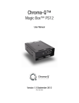
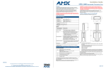
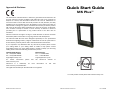
Approvals & Disclaimer
Quick Start Guide
M5 Plus™
The information contained herein is offered in good faith and is believed to be
accurate. However, because conditions and methods of use of our products are
beyond our control, this information should not be used in substitution for
customer's tests to ensure that Chroma-Q products are safe, effective, and fully
satisfactory for the intended end use. Suggestions of use shall not be taken as
inducements to infringe any patent. Chroma-Q sole warranty is that the product
will meet the Chroma-Q sales specifications in effect at the time of shipment.
Your exclusive remedy for breach of such warranty is limited to refund of
purchase price or replacement of any product shown to be other than as
warranted.
Chroma-Q reserves the right to change or make alteration to devices and their
functionality without notice due to on-going research and development.
The Chroma-Q M5 Plus has been designed specifically for the professional
entertainment lighting industry. Regular maintenance should be performed to
ensure that the products perform well in the entertainment environment.
If you experience any difficulties with any Chroma-Q products please contact
your selling dealer. If your selling dealer is unable to help please contact
[email protected]. If the selling dealer is unable to satisfy your servicing
needs, please contact the following for full factory service:
Outside North America:
Tel: +44 (0)1494 446000
Fax: +44 (0)1494 461024
[email protected]
For further information
www.chroma-q.com.
North America:
Tel: +1 416-255-9494
Fax: +1 416-255-3514
[email protected]
please
Chroma-Q is a trademark,
www.chroma-q.com/trademarks.
for
visit
more
the
Chroma-Q
information
on
website
this
at
visit
The rights and ownership of all trademarks are recognised.
For a full product manual please visit www.chroma-q.com
M5 Plus Quick Start Guide V1.0
M5 Plus Quick Start Guide V1.0
PN: 113-0500
1. Product Description
1.
The Chroma-Q M5 Plus is a colour changer which is compatible with lighting fixtures of up to 383mm x
457mm /15” x 18” rectangular aperture (15” circular aperture) and a choice of mounting plates. The unit
provides control of a user customised internal gel string containing 2 to 16 frames.
Note: The quantity of Chroma-Q M5 Plus is dependent on the size of PSU/Splitter.
2.
3.
4.
2. Operation
5.
Loading Gel String: (See Fig. 1)
1. Unscrew, remove front cover and place unit on a flat surface with motor/fan/electronics on your righthand side (assuming you’re loading from ‘tail’ end of the string, reverse if starting from ‘leader’ end of the
string).
2. Tape the top and bottom edge of tail end of the gel string to the Take Up Reel. Follow the centre line guide
scribed on the TUR.
3. Wind the gel string on the TUR manually and thereafter, gently pull the string towards you to tighten the
roll.
4. Rotate the unit to position motor/fan/electronics on your left-hand side.
5. Tape the top and bottom edge of leader end of the gel string to the TUR. Follow the centre line guide
scribed on the TUR.
6. Roll manually some of the gel string onto the TUR to check if seated correctly.
7. Plug in the unit, and check that it goes through the initialisation sequence correctly. Gel string must run
smoothly and should not bind up on the TUR’s.
8. Run test sequences for a few minutes (or 3 to 4 times, end to end) to allow the gel string to ‘bed’ in. The
unit does not have to be attached to a fixture.
Note:
• For normal operation, the start (leader) of the gel string is on the left-side TUR and the end (tail) of the
string is on the right side TUR, when viewed from the front.
• Connect and power-up colour changer first before turning lights on. The fan must be running to protect
gels from premature failure.
• High fan speed is recommended on all fixtures of 2000 Watts and above.
• Poorly optimised light bulbs may result in premature gel failure.
Modes of Operation:
1. DMX addressing mode: press UP or DOWN once to increment or decrement the value. Display shows
the current DMX address between 1-512. The unit can be set for 1 or 2 DMX channels reference to the
mode it is operating with. (see below)
2. Fan speed mode ‘Fn’: press MENU and UP or DOWN to select mode, and select between four fan
speeds, ‘Fn1’ is the slowest and ‘Fn4’ is the fastest.
3. Gel saver mode ‘GL’: press MENU and UP or DOWN to select mode, and select between Off ‘GL0’
(default) and On ‘GL1’. press and hold MENU for 2 seconds to save new setting. This feature slowly
moves the chosen gel frame back and forward to dissipate heat build-up over a larger area, extending the
life of the gel string.
4. Speed mode ‘SP’: to set scrolling speed, press MENU and UP or DOWN to select mode and, select
between Standard ‘SP1’ (default) and Fast ‘SP2’. Press and hold MENU for 2 seconds to save new
setting.
5. Display mode ‘dP’: press MENU and UP or DOWN to select mode, and select between Off ‘dP0’ (default)
and On ‘dP1’. In ‘dP1’ the display will change to diagnostic mode after 6 sec. In ‘dP0’ the display will
change to the diagnostic mode in 6 sec, then clear in another 6 sec, making 12 sec till auto-blackout.
Display will return to diagnostic mode when first button is pressed and will do the action of the second
press.
6. Remote Operation mode ‘ro’: press MENU and UP or DOWN to select mode, and select between Mode
1 ‘ro1’ – 1 ch DMX; Mode 2 ‘ro2’ – 2 ch DMX; Mode 3 ‘ro3’ – 2 ch DMX. In mode 2, ch 1 controls colour
selection and ch 2 controls fan speed. In mode 3, ch 1 controls colour selection and ch 2 controls other
functions.
(Fig.1)
(Fig.2)
Control and Power Cables: (See Fig. 2)
Connect power and control data from the power supply unit through the XLR 4-pin cable system. Pins 2 and 3
are for ANSI E1.11 USITT DMX 512-A control protocol. Pins 1(-) and 4(+) are for 24V DC power. For daisy
chaining, the XLR-4 cable should be run from the output connector on the unit to the next device in the chain.
Total cable length must not exceed more than 60m (~200ft.) with return line. Signal input is a male XLR
chassis connector and output is a female XLR chassis connector.
Power-up Display: on power-up, the unit self-calibrates and display shows the software version. When
complete, display shows DMX address mode.
Monitor Display: if left undisturbed for 5-7 sec, display will revert to ‘Monitor Mode’.
Display Flip: press MENU and DOWN button simultaneously.
Display Mode: to set auto-blackout after 12 seconds, select through mode menu under ‘dP’ and choose
between ‘dP0’ is OFF and ‘dP1’ is ON.
Reset ‘rES’: press and hold for 1 second the MENU and UP button to reset to Factory default settings.
Mounting:
The rear of the Chroma-Q M5 Plus has 6 reinforced mounting stands for M4 thread sleeve inserts which allows
compatibility with the standard 20-Lites Blinder mounting brackets. Also available is the Universal Mounting
Bracket that can be adjusted to fixture with frame size from 260mm (10-1/4”) to 409.6mm (16-1/8”). The
Chroma-Q M5 Plus is designed to be mounted in an upright position with the base below the fixture. Always
ensure that the safety wire is connected and in good working condition.
3. Further Information
Please refer to the Chroma-Q M5 Plus manual for more detailed information. A copy of the manual can be
found at the Chroma-Q website – www.chroma-q.com – under Support.
Display and Control Functions:
Control functions at the bottom panel use LED display with 3 push-button switches.
Control
Function
MENU button
Mode access, ‘Record’ and ‘Exit’
DOWN button
Decreases (-) the mode level, or value
UP button
Increases (+) the mode level, or value
3 digit display
Displays modes, monitor, or blank display
M5 Plus Quick Start Guide V1.0
M5 Plus Quick Start Guide V1.0