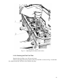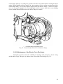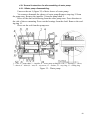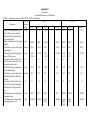
1
“MINSK MOTOR PLANT” Open Joint Stock Company D-243, D-245 Diesel Engines and Their Modifications OPERATION AND MAINTENANCE MANUAL 243-0000100RE Minsk, 2010 Contents 1. DESCRIPTION AND OPERATION ...................................................................................... 4 1.1. Description and Operation of the Diesel Engine ............................................................... 4 1.1.1. Purpose of the Diesel Engine......................................................................................... 4 1.1.2. Technical Data .............................................................................................................. 5 1.1.3. Engine Components ...................................................................................................... 8 1.2. Description and Operation of the Diesel Engine Components ......................................... 12 1.2.1. General Information .................................................................................................... 12 1.2.2. Description ................................................................................................................. 12 2. INTENDED USE.................................................................................................................. 24 2.1. Pre-operation of the Diesel Engine ................................................................................. 24 2.2. Using the Engine............................................................................................................. 24 2.2.1. Actions of the Operating Personnel When Executing the Tasks of Use ........................ 24 2.2.2. Troubleshooting .......................................................................................................... 27 2.2.3. Safety Requirements ................................................................................................... 30 3. MAINTENANCE ................................................................................................................. 31 3.1. General Directions........................................................................................................... 31 3.2. Routine Maintenance Schedule....................................................................................... 31 3.3. Diesel Engine Maintenance Procedure............................................................................ 32 4. ROUTINE REPAIRS ............................................................................................................ 57 4.1. Main Guidelines for Disassembling and Reassembling the Diesel Engine .......................... 57 4.2 Current repair of diesel engine components………………………..……………………..59 4.2.1. General instructions for disassembling of water pump………………………………...60 5. STORAGE ............................................................................................................................ 61 6. TRANSPORTATION ........................................................................................................... 62 7. DISPOSAL ........................................................................................................................... 62 Appendix А. Chart of Use of Combustive-Lubricating Materials ...……………………….……63 Appendix B. Schedule of Spare Parts and Accessories (SPA) ……………………………..……66 Appendix C. Adjustment Parameters of the Diesel Engine …………..…………….……………67 Appendix D. Adjustment Parameters of the Fuel Pumps ……..…………………………………68 Appendix E. Identification of diesel engine and turbocharger malfunctions……………….……70 Appendix F. Scheme of diesel strapping....................................................................................... 71 2 The present Operation and Maintenance Manual is intended for operators, drivers and mechanics of the machines and units equipped with the D-243 and D-245 diesel engines and their modifications. This manual provides brief technical description, proper maintenance and service rules for the D-243, D-245 diesel engines and their modifications. The reliable long-term operation of diesel engines depends on the timely and high-quality performance of all guidelines of this Operation and Maintenance Manual. Due to permanent improvement of the diesel engines, some alterations not reflected herein may be made to the design of individual assembly units and parts. If consumer is not follow to the rules and conditions of operation, technical servicing, transportation and storing conditions, specified in the present operation manual, violate integrity of manufacturer label, change diesel engine design and also use expendable materials (combustive-lubricating materials, spare parts and accessories) for technical servicing and current repairing, which not agreed with the designers documentation of OJSC «MMW», the guaranty for the diesel engine is not valid. If diesel engine owner or other person executes diesel engine and it components repairing and restoring works, during validity period of the guaranty for the diesel engine without attraction of manufacturer specialist or specialist of authorized dealer center, the guaranty for the diesel engine is not valid. 1. DESCRIPTION AND OPERATION 1.1. Description and Operation of the Diesel Engine 1.1.1. Purpose of the Diesel Engine The scope of application of the diesel engines are places with unrestricted air exchange. The diesels are designed for the operation at the ambient temperature from minus 45C up to plus 40С. The diesel engines D-243, D-245 and their modifications are designed for mounting on the tractors of the class of 1.4-2.0 tons of traction, agricultural, forest and industrial machines and units of various purposes. 1.1.2. Technical Data 1.1.2.1. The main parameters and characteristics of the diesels are given in Table 1. Table 1 Description of Units of Values parameters measureD-241 D-242 D-243 D-243.1 D-244 ment 1. Type Four-stroke diesel engine without supercharging 2. Fuel injection system 3. Number of cylinders 4. Firing order 5. Cylinder bore 6. Stroke 7. Displacement 8. Allowable longitudinal and lateral tilt of the working diesel, not more than 9. Power according to GOST 18509-88: - rated - operational 10. Rated and operational power tolerances 11. Rated rotational speed 12. Maximum idling rotational speed restricted by the governor, not more than D-245 Four-stroke diesel engine with supercharging D-245.2 D-245.4 D-245.5 Four-stroke Four-stroke diesel endiesel engine with supercharggine with ing supercharging and interim cooling of supercharging air Direct fuel injection 4 1–3–4–2 4.33 (110) 4.92 (125) 1.25 (4.75) in (mm) in (mm) gal liq US (l) degrees 20 kW kW kW 52.9 50.5 +3.7 45.6 44.1 +3.7 59.6 57.4 +3.7 61.0 58.1 +3.7 41.9 40.4 +3.7 77 74 +4.0 88 85 +4.0 60 57 +4.0 65 62 +4.0 rpm rpm 2,100 2,275 1,800 1,950 2,200 2,380 2,200 2,380 1,700 1,850 2,200 2,380 2,200 2,380 1,800 1,980 1,800 1,980 Table 1 Description of parameters Units of measurement D-241 D-242 D-243 13. Minimum stable idling rotational speed, not more than 14. Compression rate (design) 15. Direction of the engine crankshaft rotation according to GOST 22836-77 16. Maximum value of torque, not less than 17. Rotational speed at the maximum torque, not less than 18. *Specific fuel consumption in the rated power mode 19. * Specific fuel consumption in the operational power mode 20. Total oil consumption with the account of replacement for the whole warranty period of operation, not more than 21. Oil pressure in the main lubrication gallery at the temperature of 70-95C: - at the rated rotational speed - at the minimum idling rotational speed, not less than 22. Weight of the dry diesel engine with fan, alternator, air cleaner without clutch 23. Turbo-supercharger rpm 600 600 16 24. Starting device: lb.ft (N.m) rpm lb/kW.h (g/kW.h) lb/kW.h (g/kW.h) Percentage of the fuel consumption D-243.1 Values D-244 D-245 600 600 600 700 700 700 700 16 16 16 16 15.1 Right-hand (clockwise) 15.1 15.1 15.1 204.3 (277.0) 1,600 205.0 (278.0) 1,400 219.8 (298) 1,600 219.8 (298) 1,600 224.9 (305.0) 1,400 284.3 (385.5) 1,400 365.0 (495.0) 1,400 269.9 (366.0) 1,400 292.6 (396.8) 1,400 0.498 226.0 0.518 235 1.1 0.498 226.0 0.518 235 1.1 0.498 226.0 0.518 235 1.1 0.498 226.0 0.518 235 1.1 0.498 226.0 0.518 235 1.1 0.485 220 0.504 229 1.3 0.485 220 0.504 229 1.3 0.478 217 0.498 226.0 1.3 0.478 217 0.498 226.0 1.3 1035 (470) 991 (450) 991 (450) D-245.2 D-245.4 D-245.5 psig (MPa) 36.26-50.76 (0.25 – 0.35) 11.6 (0.08) lb (kg) 947/1079 947/1079 947/1079 947/1079 (430/490) (430/490) (430/490) (430/490) none none none none 947 (430) 991/1068 (450/485) none ТКР 6 or С1470В/8.12М or К 27 ТКР 6-01 or С1470В/6.12М Table 1 Description of parameters electric starter Units of measurement D-241 D-242 D-243 D-243.1 Values D-244 24.3708 or 24.3708 or 24.3708 or 24.3708 or 24.3708 or CT-142M or CT-142M or CT-142M CT-142M or CT-142M or AZJ 3124 AZJ 3124 or AZJ AZJ 3124 AZJ 3124 3124 D-245 D-245.2 D-245.4 D-245.5 24.3708 or 20.3708 or 20.3708 20.3708 or CT-142M СT-142Н or СT- СT-142Н or AZJ 142Н 3124or 20.3708 or СT-142Н Notes: 1. The values of power and fuel consumption of the engines are given for the standard atmospheric conditions and fuel density: - atmosphere pressure: 101.3 kPa (14.7 psi, 760 mm of mercury); - air temperature: 20С; - relative humidity of air: 50%; - fuel density: 0.83 t/m3 (6.92 lb/gal liq US). When measuring the parameters of the diesel engine in the conditions different from the standard ones the values of the power and specific fuel consumption shall be corrected in accordance with GOST 18509-88. 2* The specific fuel consumption shall be considered confirmed, if the deviation does not exceed 5%. 1.1.3. Engine Components The D-243 diesel engines in accordance with Figs 1 and 2 and the D-245 diesel engines in accordance with Figs 5 and 6 are basic models. Their modifications differ from the basic model in the power regulation, standard equipment, starting device and design of some parts. Depending on the purpose, the diesel engines may be equipped with additional assembly units: air compressor, gear pump of the steering booster with drive and clutch disk assemblies. When installing on the tractor (machine), the diesel engine shall be fit additionally with water and oil radiator, electric equipment as well as control instruments. The diesel engines can be started by an electric starter. The design differences of the diesel engines from the basic model consist in the following: - in the D-241 diesels, in accordance with Fig. 4, the exhaust connection is altered with installation of a muffler in the zone of the fourth cylinder; - the D-242 diesel engines, in accordance with Fig. 5, as well as on the D-244, are fitted with the crankshaft without counterweights, fan with the diameter of 450 mm (17.72 in), shortened intake manifold, crankcase pulley with the diameter of 170 mm (6.69 in), side nipple of the air cleaner with the diameter of 57 mm (2.24 in), oil pump and its driving gear unified with the D50 diesel. The main differences of the D-245 diesel engine from the D-243 one: - the turbo-supercharger is installed; - the design of the connections of the intake and exhaust manifolds, crankshaft pulleys, water pump and alternator; - an additional V-belt is introduced for driving the fan and alternator; - the special sprayers for cooling the pistons with oil jets are provided in the main supports of the cylinder block; - the fuel pump is equipped with an antismoke corrector (ASC); - the cylinder head has insert valve seats made of heat- and wear-proof alloy; - an insert of special cast iron is founded under the first compression ring; - the upper compression ring has trapezoid shape; - the crankshaft and connecting rods are made of stronger materials; - six-blade fan with he diameter of 456 mm (17.95 in); - high-capacity oil pump; - air cleaner with the diameter of 270 mm (10.63 in); - centrifugal oil filter has increased capacity; - linger flywheel pins for installation of a double-disk clutch. The main differences of the D-245.2 diesel engine from the D-245 one: - a supercharging air cooler is fitted; - adjustment parameters of the fuel pump; - three-grooved pistons К.343N manufactured by the "Petar Drapshin", Serbia; - three-ring set (6-2143-25/3, 6-0970-05/4 and 7-2146-54-0/3) of piston rings manufactured by the "Buzuluk" Company, Czech Republic; - Cylinder sleeves 245-1002021-А manufactured by the “Krotoszin” Company, Poland. The diesel engines are equipped with the tachometer drives corresponding to the rated rotational frequency of the crankshaft. The tachometer drive housing is marked with numbers. The number 40 indicated that the reduction gear is intended for the engine with the rated rotational speed of 1,700 rpm, 50 – 1,800 rpm, 80 – 2,100 rpm and 90 – 2200 rpm. 8 Fig. 1 – D-243 Diesel Engine (Left View). Fig. 2 – D-243 Diesel Engine (Right View) 9 Fig. 3 – D-241 Diesel Engine (Right View). Fig. 4 – D-242 Diesel Engine (Right View). 10 Fig. 5 – D-245 Diesel Engine (Left View). Fig. 6 – D-245 Diesel Engine (Right View) 11 1.2. Description and Operation of the Diesel Engine Components 1.2.1. General Information As seen in Fig. 7, the diesel engine consists of the cylinder block, cylinder head, crank mechanism, valve gear link as well as assemblies and units of the feed, lubrication, cooling and starting systems as well as electric equipment. 4 3 5 6 8 9 10 11 12 2 1 14 13 1 – oil pump; 2 – fan; 3 – water pump; 4 – piston pin; 5 – connecting rod; 6 – cap; 7 – piston; 8 – cylinder sleeve; 9 – cylinder head cover; 10 – cylinder head; 11 – cylinder block; 12 – flywheel; 13 – counterweight; 14 – crankshaft; 15 – oil collector. Fig. 7 – D-243 Diesel Engine (Longitudinal Section). 1.2.2. Description 12 1.2.2.1. Cylinder Block The cylinder block is the main engine case and is designed as a special rigid cast-iron alloy mono-block. Four removable sleeves made of special cast-iron, are fixed in block bores. Sleeves are installed into the cylinder block in two centring lands, the upper and lower ones. In the upper land the sleeve is fixed by means of a shoulder while in the lower land it is sealed by means of two rubber rings located in cylinder block grooves. According to their internal diameter, the sleeves are divided into three size groups, the large (Б=L), medium (С=M) and small (М=S) ones. The group is marked on the inserting cone of the sleeve. The sleeve sizes are given in Section 4.1. The diesel engine shall be fitted with sleeved of the same size group. The coolant circulates in the space between cylinder block and the sleeves. The end walls and cross hatches of the cylinder block have special lugs in the lower portion to form upper supports of the crankshaft. The lugs are covered with caps serving as lower supports of the crankshaft. The lugs together with the caps form beds for main bearing shells. The beds are machined in assembly with the caps; therefore the caps are not interchangeable. The cylinder block has a main oil channel supplying oil via a number of transverse channels to main bearings of the crankcase, and then to the camshaft journals. The cylinder block of the D-245 diesel engine has sprayers in the second and forth supports of the crankshaft. These sprayers serve for cooling the pistons with oil jets. On the external surfaces of the cylinder block there are machined mating faces for mounting the centrifugal oil filter, water pump, coarse and fine fuel filters as well as oil filler neck. 1.2.2.2. Cylinder Head The cylinder head is a cast-iron casting, in the inner passages of which there are intake and exhaust channels to be closed by means of the valves. To ensure the heat abstraction, the cylinder heat has inner passages for coolant circulation. The cylinder head of the D-245 diesel engine has inserted valve seats made of heat- and wear-proof alloy. On the top of the cylinder head there are rocker shaft assembly, rocker shaft brackets, head cover, intake manifold and cover cap, covering the camshaft valve gear link. Four fuel injectors are mounted in the cylinder head from the side of the fuel pump, and the exhaust manifold – from the side of the alternator. To seal the joint between cylinder head and cylinder block, a gasket of asbestos-steel web is inserted. The cylinder sleeve borings and oil passage are back-lined by sheet steel. When assembling the engine at the factory, the cylinder holes of the gasket are back-lined additionally with fluoroplastic split rings. 1.2.2.3. Crank Mechanism The main parts of the crank mechanism are the crankshaft, connecting rods, pistons, piston rings, piston pins, main bearings and connecting rod bearings as well as flywheel. The crankshaft is made of steel. It has five main bearing journals and four rod journals. Inside of the crank-pin journals, oil chambers are provided for centrifugal cleaning of lubrication oil. The oil chambers of the journals are plugged with threaded plugs. Axial force of the crankshaft is taken by four split rings made of aluminium alloy that are fixed in the bores of the cylinder block and cover of the fifth main bearing. The counterweights are provided for reducing the loads imposed on the bearings from the inertia forces at the first, fourth, fifth and eight crank webs. At the front and at the back the crankshaft is sealed by means of collars. The timing gear (crankshaft gear), oil pump driving gear, water pump and alternatordriving pulley are installed on the front end of the crankshaft. The flywheel is fastened to the rear flange of the shaft. 13 The crankshaft may be manufactured and installed in the engine of two production sizes (nominal values). The crankshaft with the connecting rod and main bearing journals manufactured according to the second nominal size has additional marking on the first web. The size of the main and connecting rod webs as well as respective marking of the crankshaft is given in Section 4.1. The piston is made of aluminium alloy. The combustion chamber is made in the piston head. The piston has four grooves in its upper part; the first three grooves are intended for filling the compression rings and the fourth for the oil ring. The piston of the D-245 engine is fitted with an insert of special cast iron under the upper trapezoid-shaped compression ring. The holes for piston pins are bored in the piston pin boss. According to the external diameter of the skirt, the pistons are sorted according to three size groups (Б=L, С=M and М=S). The group is marked on the piston head. The piston sizes are given in Section 4.1. When being mounted in the engine, the sleeves and pistons must be of the same size group. The piston rings are made of cast iron. The upper compression ring is chromium-plated, having rectangular cross section and no marking. It is mounted in the groove in arbitrary manner. The second and third compression rings are conic and have marking “up” on the end surface at the lock. The oil ring is box-shaped and fitted with spiral steel extender. The upper compression ring of the D-245 engine is made of high-strength cast iron and has the shape of isosceles trapezium while the other rings are unified with those of the D-243 engine. The diagram of mounting of the piston rings is given in Fig. 33. The piston pin is hollow, made of chromium-nickel steel. The axial shift of the pin in the bosses is restricted by stop rings. The connecting rod is made of steel and has double-T section. A bush is pressed in its upper head. There are holes for lubricating the piston pin in the upper head and bush of the connecting rod. The insert bed in the lower head of the connecting rod is bored as an assembly with the cover; therefore the connecting rods are not interchangeable. The connecting rod and its cover have the same numbers stamped on their surfaces. Moreover, the connecting rods have the weight groups according to the weights of the upper and lower heads. The designation of the group according to the weight is stamped on the end face of the connecting rod upper head. The engine shall be fitted with the connecting rods of the same group. The inserts of the main and connecting rod bearings of the crankshaft are made of steel and aluminium. The inserts of the main and connecting rod bearings of two sizes in accordance with nominal sizes of the crankshaft are used in the diesel engines. The four repairing sizes of the inserts are provided also for repairing the diesel engine. The flywheel is made of cast iron and bolted to the crankshaft flange. The gear ring is pressed onto the flywheel. 1.2.2.4 Valve Gear Link The valve gear link includes gears, camshaft, intake and exhaust valves as well as their fasteners and actuators, such as followers (pushers), push rods, rocker arms, rocker shafts, adjusting screws with nuts, plates, valve keepers, valve springs, brackets and rocker axle. The camshaft is supported by three journals and is connected with a crankshaft via timing gears. The three bushes pressed in the cylinder block bores serve as camshaft bearings. The first bush (from the fan side) made of aluminium alloy has a thrust shoulder keeping the camshaft from the axial travel; the other bushes are made of cast iron. The cam followers (pushers) are made of steel and have spherical bottoms. Since the camshaft cams are made with small inclination, the push rods are in rotary motions during the work. 14 The push rods are made of steel bars. The spherical part that goes inside the cam follower and the rod cup are hardened. The rocker arms are made of steel. They swing on the rocker shaft supported by four brackets. The outermost brackets have increased hardness. The rocker arm axle is hollow and has eight radial holes to supply lubrication oil to the rocker arms. The rocker arms travel along the axle is limited by the spacer springs. The intake and exhaust valves are made of high-temperature steel. They travel in guide bushes pressed in cylinder heads. Each valve is closed by means of two springs: the outer and inner ones. The springs actuate the valve via plates and valve keepers. The Seal collars fixed on guide bushes do not let oil penetrate into engine cylinders through clearances between the valve stems and the guide bushes. 1.2.2.5. Fuel System As shown in Fig. 8, the engine fuel system consists of the fuel pump, injectors, low and high pressure pipes, air cleaner, intake and exhaust manifolds, coarse and fine fuel filters as well as the fuel tank mounted onto the tractor (machine). The fuel system of the D-245 diesel engine includes a turbo-supercharger. 15 1 – fuel tank; 2 – coarse fuel filter; 3 – fuel pipes; 4 – fuel pump; 5 – high-pressure fuel pipe; 6 – fine fuel filter; 7 – air cleaner; 8 – coarse air filter; 9 – electric torch heater; 10 – intake manifold; 11 – muffler; 12 – exhaust manifold; 13 – fuel injector. Fig. 8 –D-243 diesel engine feeding system diagram. 16 1.2.2.5.2. Fuel Pump The D-243 diesel engine and its modifications are equipped with the high-pressure fuel pump 4UTNI and the D-245 engine and its modifications – with the pumps 4UTNI-T or 4UTNM-T. All the pump models are driven from the engine crankshaft via timing gears. The fuel pumps are equipped with all-mode governors and piston-type priming pumps. The pump governor contains the fuel feed corrector, automatic fuel feed intensifier (for starting the engine) and, in the 4UTNI-T and 4UTNM-T pumps there is also the pneumatic smoke restrictor (pneumatic corrector). The fuel-priming pump is mounted on the housing of the high-pressure pump and driven by the eccentric of the camshaft. The working parts of the fuel pumps are lubricated with flowing oil coming from the engine lubricating system into the pump housing through the special hole in the flange. The oil is drained from the pump into the engine pan through the special channel in the flange. When mounting a new or repaired pump onto the engine, it is necessary to fill it with 200...250 cm3 (0.42-0.53 pt liq US) of engine lubrication oil through the oil filler hole in the regulator cover. 1.2.2.5.3. Fuel Injector The fuel injector is intended for spraying the fuel into the engine cylinder. It ensures the necessary atomisation of fuel and restricts the beginning and end of the feed. The diesels are equipped with fuels injector fitted with closed-type five-hole atomizers 17.1112010-01 (manufactured by the “KA” Joint-Stock Company) or 171.1112010-01 (manufactured by the “AZPI” Closed Joint-Stock Company). The fuel injector 17.1112010-01 (the “KA” Joint-Stock Company) has the marking "171", 171.1112010-01 (manufactured by the “AZPI” Closed Joint-Stock Company) – “171-01” while the fuel injector atomizer has the marking “17”. The marking is stamped on the fuel injector housing and on the atomizer body. 1.2.2.5.4. Course Fuel Filter The course fuel filter serves for the preliminary purification of fuel by removing mechanical contaminants and water. The course fuel filter consists of the housing, slinger with the screen element, diffuser and cup with a damper. The fuel sediment shall be drained out from the hole in the sleeve bottom to be closed with a plug. 1.2.2.5.5. Fine Fuel Filter The fine fuel filter is intended for final purification of fuel. The fine fuel filter has a replaceable paper element. When passing through the blinds of the paper filter element, the fuel becomes free of mechanical contaminations. In the lower portion of the filter housing there is a hole for draining the sediment with a plug. There is a vent plug on the filter cover for bleeding air from the fuel system. 17 1.2.2.5.6. Air Cleaner and Inlet Line The air cleaner is intended for purification of air to be sucked into the cylinders. The air-cleaner of the diesel engine is combined: the dry centrifugal purification and oil dust-trap with wet kapron filter. In the air-cleaner housing there are three filter elements of kapron bristle having different diameters. The D-245 diesel and its modifications can be fitted also with an air-cleaner consisting of the main and control paper filter cartridges. To ensure the better filling of the cylinders with air, the D-241, D-243 engines are equipped with the intake manifold with selected length and diameter of intake pipe and port of the intake manifold. In the intake manifold port there is a shutter for emergency stop of the engine. The shutter is controlled from the cabin of the tractor (machine). The D-242 and D-244 diesels are equipped with a simplified intake manifold without the emergency stop shutter. All the diesel engines equipped with electric starter have the electric torch pre-heater, which is intended for preheating the air to be sucked into the cylinders with the purpose of easing the engine start at low ambient temperatures. 1.2.2.5.7. Turbo-Supercharger The D-245 diesel engine and its modifications are equipped with the turbo-supercharger using the energy of exhaust gas for supercharging the air into the engine cylinders. The principle of operation of the turbo-supercharger consists in directing the pressurized exhaust gas from the engine cylinders into the turbine scroll channels through the exhaust manifold. When expanding, the gas rotates the rotor connected with the compressor impeller, which sucks the air through the air-cleaner and delivers it into the engine cylinders under pressure. As shown in Fig. 9, the turbo-supercharger is designed according to the following scheme: radial centripetal turbine and single-stage compressor with the console arrangement of wheels relatively to the supports. The rotational speed of the compressor, feed and pressure of the air discharged depend on the diesel engine operating mode. The turbo-supercharger turbine housing 2 is founded of high-strength cast iron. The flow-through part of the turbine for passing the exhaust gas is formed by the housing and the turbine wheel. The compressor housing 11 is founded of aluminium alloy, its flow-through part is formed by the housing and the compressor wheel. The housings of the turbine and the compressor are fastened to the housing of the bearings 14, which is founded of high-strength cast iron. The turbine wheel 1 is founded of heat-proof alloy and welded to the rotor wheel. The compressor impeller 6 is founded of aluminium alloy and fastened to the shaft by means of a special nut. The rotor shaft rotates in the radial bearing made in the form of floating non-rotating mono-bush 3. The mono-bush is fixed in the housing of bearings by means of a pawl. The axial travel of the rotor is perceived by the thrust bearing 12. The turbo-supercharger bearings are lubricated and cooled with oil coming from the centrifugal oil filter through the pipeline. Both radial and thrust bearings provide additionally for the centrifugal oil cleaning. The oil is drained to the engine crankcase through an oil-draining pipe. Between the compressor and the turbine there are gas and oil seals in the form of spring rings 8 and 15 mounted in the rotor grooves. To improve the efficiency, an oil-guard is mounted from the compressor side and a screen from the turbine side. 18 1 – turbine wheel with shaft; 2 – turbine housing; 3 – mono-bush; 4 – oil-guard; 5 – eccentric ring; 6 – compressor wheel; 7 – special nut; 8, 15 – O-rings; 9 – diffuser; 10 – cover; 11 – compressor housing; 12 – thrust bearing; 13 – distance bush; 14 – middle housing (housing of bearings). Fig. 9 – Turbo-supercharger. 1.2.2.6. Cooling System As seen from Fig. 10, the diesel is cooled by means of the liquid-type cooling system with forced circulation of the coolant from the centrifugal pump. The temperature of the coolant in the system is controlled by means of a distance temperature gauge, the sensor of which is mounted in the cylinder head. In the D-245 diesel engine and its modifications, the place for mounting the sensor in the thermostat housing is also provided for. The operation of the diesel engine is prohibited, if the coolant overheating indicator lights up. The temperature of the coolant in the cooling system must be maintained within 75-95C. 19 Fig. 10 – Diagram of the Cooling System The thermostat with solid filler serves to speed up the engine warming-up after starting it and automatic regulation of the temperature regime at various loads and ambient temperatures. The water pump, fan and alternator are driven from the engine crankshaft pulley by means of a V-belt. On the D-245 engine these units are driven by means of two belts. The "Litol-24" lubricant is injected into the bearing cavity of the pump during the assembling. The pump bearings need not lubrication for the whole period of operation of the diesel engine. The cooling system of the engines equipped with starting engines is connected with the cooling system of the starting engine. The cooling jacket of the starting engine cylinder communicates with the cooling jacket of the diesel engine cylinder head and the cooling jacket of the cylinder head of the starting engine communicates with the housing of the diesel engine thermostat. 1.2.2.7. Lubricating System The diesel engine has a combined lubricating system. The bearings of the crankshaft and camshaft, bushes of the intermediate gear and fuel-pump driving gear, the connecting-rod bearing of the air-compressor crankshaft, as well as valve driving gear and on the D-245 engine also the turbo-supercharger shaft bearing, in accordance with Fig. 11, are lubricated under pressure. The sleeves, pistons, piston pins, push rods, pushers and cams of the camshaft are splash lubricated. The oil pump 12 is a gear-type, single-section one bolted to the first main bearing cover. The pump delivers oil via pump outlet pipe and cylinder block channels to the centrifugal filter 3, where it is cleaned from foreign particles, combustion and wear products. Cleaned oil is transferred from the centrifugal oil filter to the radiator for cooling, and, on the D-245 engine, additionally to the turbo-supercharger shaft via oil duct. The oil is transferred from the oil radiator into the diesel main pipelines. 20 In the centrifugal oil filter housing there are reducing 7, drain valve 8 and safety valve 10. Upon starting the diesel engine the non-heated oil comes directly to the diesel engine pipeline through the reducing (radiator) valve bypassing the radiator due to high resistance of the radiator. The safety valve (centrifugal filter valve) serves for maintaining the oil pressure before the filter rotor of 101.8 psig (7 kgf/cm2). When the pressure exceeds the above value, some noncleaned oil is drained through the valve into the engine crankcase. Both reducing and safety valves are not adjustable. It is strictly prohibited to turn out the plugs of the reducing and safety valve. The drain valve is adjusted to the pressure if 29...43.5 psig (2.0...3.0 kgf/cm2) and used for maintaining the necessary oil pressure in the main pipeline of the diesel engine. The surplus oil is drained into the engine crankcase through the valve. From the main gallery of the engine the oil is passed to all the main bearings of the crankshaft and necks of the camshaft. From the main bearings it is passed to all the connecting rod bearings. From the first main bearing oil is passed through the special channels to the bushes of the intermediate gear and the fuel pump driving gear as well as to the fuel pump. The parts of the valve gear link are lubricated with oil supplied from the rear bearing of the camshaft through the channels in the cylinder block, hole in the fourth rocker arm into the inner cavity of the rocker shaft and through the hole to the rocker arm bush and then to adjusting screw and push rod. 1 – oil radiator; 2 – piston cooling fuel injectors; 3 – centrifugal oil filter; 4 – protective strainer; 5 – oil-filler neck; 6 – plug of the oil sump; 7 – reducing valve; 8 – drain valve; 9 – pressure gauge; 10 – safety valve; 11 – oil receiver; 12 – oil pump. Symbols: filtered oil, hot filtered oil, cold non-filtered hot oil to be drained to the oil sump 21 filtered hot oil to be drained into the oil sump non-filtered hot oil splash-lubrication of parts Fig. 11 – D-245 diesel engine lubricating system. The air-compressor is supplied with oil from the main oil gallery via engine block channels and special pipe. From the air-compressor oil is drained into the engine crankcase. 1.2.2.8. Electric Equipment and Starting System The electric equipment of the D-243 diesel engine and its modifications may include the G964.3701-1 or G964.3701-1-2 alternators with the rated capacity of 1 kW and rated voltage of 14 V, or G994.3701-1 alternators with the rated power of 1 kW and rated voltage of 28 V, and that of the D-245 diesel engine and its modifications may include the G968.3701-1 or G968.37011-2 alternators with the rated capacity of 1 kW and rated voltage of 14 V or G998.3701-1 alternators and rated capacity of 1 kW and rated voltage 28 V. The alternator is a brushless AC generator with built-in compact voltage regulator and single-sided electromagnetic excitation. The alternator operates in parallel with the storage battery and serves for recharge of the latter as well as for supplying the electric power consumers mounted on the machine (tractor) with DC current. For starting the diesel engine, an electric starter. The starting device of the diesel engines equipped with electric starters includes also the electric touch pre-heater. The diesel engines are equipped with the 24.3708 starters with the power of 4 kW (5.3 hp) at the voltage of 12 V or the ST 142M or ARJ3124 ones. On the customer’s request, the diesels may be equipped with the 20.3708 starter with the power of 5.9 kW (8.0 hp) at the voltage of 24 V or the ST142N one. The starter is a DC series-excitation electric motor. The starter is switched on remotely by means of electromagnetic starter relay and starter switch. The electric torch pre-heater serves for pre-heating of the air to be sucked into the cylinders for the purpose of facilitating the engine start. To facilitate the engine start at low ambient temperatures all the diesels are provided with the places for mounting the PZhB-200G pre-starting pre-heater. 1.2.2.9. Air Compressor The air compressor is intended for supplying the pneumatic braking system of trailers with compressed air and inflating the tyres. The air compressor is a piston-type one-cylinder air-cooled one. The air compressor is driven from the fuel pump driving gear. The air is sucked into the cylinder of the air compressor from the intake pipe of the diesel engine through a plate valve. The air compressor parts are lubricated with the oil coming from the lubricating system of the diesel engine. From the air compressor the oil is drained into the diesel crankcase. 22 1.2.2.10. Controls and Instruments The diesel engine is controlled remotely, from the operator’s place. The diesel engine controls and instruments are to be mounted by the user when installing the engine in the tractor (machine). The rotational speed of the crankshaft is changed by means of the fuel pump governor lever. When moving the lever to the rearmost position (towards the flywheel) the engine runs at the highest rotational speed and when moving the lever to the extreme front position (towards the fan) the fuel feed is shut (turned off). When starting the diesel engine, the electric torch pre-heater and starter are switched on by means of the three-position switch of the VK-316-B type. When the switch is set to the I position, the electric circuit of the heating coil of the pre-heater is energized, when it is set to the II position, the starter circuit is closed and the fuel valve of the pre-heater is opened. The instruments for monitoring the diesel run are located in the tractor (machine). The pressure gauge of oil in the lubricating system is connected to the union of the centrifugal oil filter via the oil duct. The sensor of the emergency oil pressure alarm of the D-243, D245 diesel engines is located in the housing of the centrifugal oil filter and the sensor of the emergency coolant temperature alarm is mounted in the thermostat housing. The sensor of the air-cleaner clogging alarm is mounted in the intake path of the diesel engine. The sensor of the coolant temperature gauge in the cooling system is located in the cylinder head. The crankshaft rotational speed and the number of engine service hours are monitored by means of the tachometer with the counter of the number of engine service hours driven from the engine camshaft via flexible shaft and reduction gear. The number of running house of the D-242 and D-244 diesel engines can be monitored also by means of the SCh-114B up counter mounted on the camshaft cover instead of the reduction gear and driven from the camshaft. The air compressor is controlled by means of the handle located on its housing. To engage of disengage the compressor, it is necessary to set the handle to the required position. 23 2. INTENDED USE 2.1. Pre-operation of the Diesel Engine When preparing the new diesel engine for operation, perform its depreservation. To do this, remove the protective shrouds and plugs mounted on the engine. Check and adjust, if necessary, the fan belt tension. Fill all the refill tanks with working oils, fuel and coolant (the refill tank capacities, description and marks of the fluids are given in Appendix A). Fill the fuel-feeding system with fuel and purge this system to remove air from there. For performing the maintenance and eliminating faults, an individual complete set of spare parts, tools and accessories (their schedule is given in Appendix B) is enclosed to each diesel engine. 2.2. Using the Engine 2.2.1. Actions of the Operating Personnel When Executing the Tasks of Use 2.2.1.1. General Guidelines To ensure the long-term and trouble-free operation of the diesel engine follow the main guidelines stated below: - check regularly the condition of fastening the assembly units and, if necessary, retighten the fasteners; - before starting the engine check the level of oil in the engine crankcase and coolant in the radiator; - after starting the engine let it run first at the minimum idling speed for 2-3 min with increasing gradually this speed up to its maximum value prior to engaging the load; - load the engine only after the cooling system fluid has warmed up to plus 40C; - prior to putting the diesel engine into operation under load, perform its running-in following Section 2.2.1.5; - idling of the diesel engine for more than 15 minutes is not recommended; - do not overload the diesel, during the operation monitor the readings of the instruments; - do not stop the engine by shutting the intake path by the emergency shutter except for the emergency cases; - perform the maintenance of the diesel engine in proper time following the guidelines of Section 3; - use only the fuel and oil of the marks specified in this Manual; - maintain the engine clean, do not allow any leakage of fuel, oil and coolant or suction of non-cleaned air into the cylinders; - the diesel can be operated at the longitudinal and lateral tilts not exceeding 20. To avoid disturbances in the operating process when running the engine at the altitude of more than 4,918 ft (1,500 m) above sea level, adjust the fuel pump to reduce its capacity in accordance with Table 2. Table 2 Altitude, ft (m) Atmospheric pressure, psi Reduction of the pump ca(mm of mercury) pacity, % 4,918-6,557 (1,500-2,000) 12.18 (630)-11.60 (600) 10 6,557-8,197 (2,000-2,500) 11.60 (600)-10.83 (560) 15 8,197-9,836 (2,500-3,000) 10.83 (560)-10.15 (525) 20 24 The operation of the diesel at the altitude exceeding 9,836 ft (3,000 m) above sea level is not recommended. 2.2.1.2. Starting the engine by means of the starter When starting the diesel engine: - set the gear shifting lever of the tractor (machine) to the neutral position; - set the “ground” switch to the ON position; - set the fuel pump control lever to the position corresponding to the maximum feed; - switch on the electric torch pre-heater by rotating the switch to the I position; - after 30-40 s, during which the pre-heater spiral will warm up, disengage the clutch of the tractor (machine), switch on the starter by setting the switch to the II position and start the diesel engine; - after starting the diesel engine engage smoothly the clutch. The duration of the continuous run of the starter shall not exceed 15 s. If the diesel engine fails to start, repeat the starting procedure 30-40 s later. If the diesel engine fails to start after three attempts, locate and eliminate the trouble. When the diesel engine is warmed up as well as in summer it can be started without turning on preliminarily the electric torch pre-heater by turning the switch directly to the II position without holding it in the I position. 2.2.1.3. Stopping the diesel engine Before stopping the diesel engine after removing the load, let it work for 3-5 min first at the medium and than at the minimum idling speed for reducing the temperature of the coolant and oil and then stop the diesel engine by setting the fuel pump control lever to the position corresponding to the fully shut fuel feed. After stopping the diesel set the «ground» switch to OFF position. Failure to comply with these rules when stopping the D-245 diesel and its modifications can cause the damage of the turbo-supercharger. 2.2.1.4. Operational running-in of the diesel The operation of the diesel under loading without preliminary running in is not allowed. The diesel engine must be run-in by the operating organization. It is recommended to stick to the following sequence of works: preparing the diesel engine for running in, running in the engine on idling and under load for 30 hours and preparing the engine for operation. When preparing the diesel for operational running in follow Section 2.1 "Pre-Operation of the Diesel Engine". Start the diesel engine and, having made sure that it is running properly, proceed to running in. First, run in the engine on idling for 5 minutes with increasing smoothly its speed up to the maximum value. Run in the engine installed in the tractor under load by performing light transport (trailer with the load of 2-3 t (4,405-6,608 lb)) and field (harrowing, sowing, ground treatment with a cultivator, etc.) works while increasing the load on various gears. Overloading the diesel engine is not allowed. After running in the diesel engine perform the following operations: - check the bolts fastening the cylinder head for tightening; - check the clearance between the valves and rocker arms; - clean the rotor of the centrifugal oil filter; - replace the oil in the engine crankcase; 25 - drain the sediment from the coarse and fine fuel filters; - check the fan belt for tension; - check the external threaded connections. If necessary, eliminate the deviations detected. 2.2.1.5. Peculiarities of Operation and Maintenance of the Diesel Engine in Winter Conditions At low ambient temperature the operation of the diesel engine becomes more difficult. To ensure its undisturbed and reliable operation in winter period, which begins with lowering of the ambient temperature down to plus 5С and lower, prepare the engine for the winter period of operation in proper time. To do this, perform its routine maintenance procedures supplemented with the operations of seasonal maintenance. Equip the engine with a heating cover (bonnet) and, if necessary, with the PZhB-200G liquid-type pre-starting pre-heater and fill the cooling system with the fluid not becoming frozen at low temperature (tosol, antifreeze). In case of using water in the cooling system, pour only hot water (50-80C) at the ambient temperature of 0C and below. When transiting to the winter regime of operation use only winter sorts of oil and fuel. Fill the engine crankcase with only motor oils according to the Chart of Use of Combustive-Lubricating Materials (Appendix A). Without pre-starting pre-heater, the diesel engine filled with the M-8G2 motor oil is started reliably by means of the electric starter at the temperatures down to minus 10C. Using the M-4з/12G motor oil in the lubricating system ensures the reliable start of the diesel engine at the temperatures down to minus 20C. At the ambient temperature of lower than minus 20C the diesel engine shall be heated by means of the PZhB-200G pre-heater before starting and, if the pre-heater is not available, the cooling system shall be poured through with hot water and fill the engine crankcase with oil preheated up to the temperature of 70…80C. If the M-8G2 winter motor oil is not available, it is allowed to use the M-10G2 summer oil with addition of 10…12% of diesel fuel. When doing this, the engine shall be only filled with the mixture of oil with diesel fuel after the oil and fuel have been mixed thoroughly. If the winter sorts of fuel are not available, it is allowed to add burning kerosene to the summer diesel fuel in the following quantities: - 10% at the temperature from 0 down to minus 10C; - 20% at the temperature from minus 10 down to minus 20C; - 30% at the temperature from minus 20 down to minus 25C; - 40-50% at the temperature below minus 25C. To facilitate the start of the diesel installed in the tractor at low temperature, proceed as follows: - disengage the pump of the tractor hydraulic system; - when turning on the starter disengage the clutch and engage it smoothly after starting the diesel engine. The standard means for facilitating the engine start, for instance, electric torch pre-heater of intake air or starting facility for injecting flammable liquid are used in all the cases of starting the diesel engine at low temperature. Do not heat the air to be sucked before the air cleaner using the naked flame and do not start the diesel engine by towing the tractor (machine). In cases of long-term stops drain water from the cooling system to avoid breakage of the radiator or engine due to freezing of water. Make sure that water is drained off completely and will not become frozen in the drain cocks of the radiator and cylinder block. For this purpose clean the cocks by means of wire. To speed up the draining of water from the system open the radiator filler neck plug. After draining the water keep the cocks open. 26 In case of leaving the tractor (machine) on the open place at the end of the shift, set the fuel pump control lever to the position corresponding to the maximum feed to facilitate the subsequent start. 2.2.2. Troubleshooting Possible troubles in the diesel engine during the operation and recommendations for corrective actions are enlisted in Table 3. Table 3 Trouble and its appearance 1 1.1 The diesel engine fails to start Air in the fuel system 1.2 Fuel pump is faulty Remedy Purge the system by means of the manual priming pump. Eliminate the suction of air in the fuel system Remove the fuel pump from the diesel engine and send it to the repairing workshop 2 The diesel does not develop full power 2.1 The fuel pump controlling lever does Adjust the fuel pump controlling rods not reach the stop 2.2 The filtering element of the fine fuel fil- Replace the filtering element of the fine fuel filter ter is clogged 2.3 The fuel injectors are faulty Locate faulty fuel injectors, wash the atomizers and clean their nozzle holes, if necessary, replace the atomizers 2.4 The injection dwell angle is set improp- Set the ignition dwell angle as recommended erly 2.5 The air cleaner of the diesel engine is Perform the air cleaner maintenance clogged 2.6 The fuel pump is faulty Remove the fuel pump from the diesel engine and send it to the repairing workshop 2.7 The supercharging pressure is reduced Remove the turbo-supercharger from the engine and send it to the repairing workshop 3 The engine idling is unstable 3.1 Penetration of air into the fuel system Remove air from the fuel system 3.2 The idling spring of the fuel pump is not Adjust the idling spring (in the engines with the adjusted 4UTNI and 4UTNI-T fuel pumps) 3.3 The fuel pump is faulty Remove the fuel pump from the diesel engine and send it to the repairing workshop 4 The engine emits smoke in all the operating modes 4.1 The engine emits black smoke 4.1.1 The engine air cleaner is clogged Perform the air-cleaner maintenance 4.1.2 The fuel injector atomizer needle is Find the faulty injector, clean or replace the atstuck omizer and adjust the injector 4.1.3 The fuel pump is faulty Remove the fuel pump from the diesel engine and send it to the repairing workshop 27 Continuation of Table 3 Trouble and its appearance Remedy 4.2 The engine emits white smoke 4.2.1 The engine is overcooled 4.2.2 4.2.3 4.2.4 4.3 4.3.1 4.3.2 5 5.1 6 6.1 6.2 6.3 6.4 6.5 6.6 7 7.1 a) b) 7.2 8 8.1 a) Warm up the engine. During the operation, keep the coolant temperature within the range 75…95C Water in fuel Change the fuel The clearances between the valves and Adjust the clearances between the valves and the the rocker arms are not adjusted rocker arms The injection dwell angle is set improp- Set the ignition dwell angle as recommended erly The engine emits blue smoke Penetration of oil into the combustion Replace the worn parts of the sleeve and piston chamber due to wear and tear of the group parts of the sleeve and piston group Excessive oil in the engine crankcase Drain excessive oil while checking the level according to the upper mark of the dipstick The engine overheats The coolant in the radiator boils Clean the radiator from dust and dirt and the cooling system from the scale. Adjust the fan belt tension The oil pressure in the warmed-up engine is lower than the allowable value The pressure gauge is faulty Replace the pressure gauge (if necessary) after checking the oil pressure by means of the reference pressure gauge Leakage in joints of the oil pipelines Locate the leaking joint and restore the leakproofness The oil pump is faulty Locate and eliminate the failure The oil level in the engine crankcase is Add oil up to the upper mark of the dipstick lower than the allowable one Jamming of the drain valve of the cen- Wash the valve and adjust the pressure in the lubritrifugal oil filter cating system in accordance with Fig. 18. Extreme wear and tear of the junction Regrind the crankshaft pivots and install the inbetween the crankshaft pivots and bear- serts of the repair-size bearings ings Turbo-supercharger The turbo-supercharger rotor does not rotate (no distinctive high-pitch tone sound is heard): Presence of foreign objects preventing Remove the intake and exhaust pipes and rethe rotor from rotation move the foreign objects Seizure of the rotor in the bearings Replace the turbo-supercharger Increased ejection of oil from the side Remove the turbo-supercharger from the diesel of the compressor or turbine, leakage in engine and send it to the repairing workshop the oil seals of the turbo-supercharger Starter When switching on the starter, the solenoid starter switch does not operate (no distinctive clock is heard): Insufficient tightening or oxidization of Clean the contacts and tighten the terminals 28 Continuation of Table 3 Trouble and its appearance b) c) d) 8.2 8.3 a) b) c) d) 8.4 8.5 9 9.1 a) b) 9.2 a) b) c) 9.3 9.4 the storage battery terminals The storage battery is discharged or faulty Scale of the RS-502(Sh) switch contacts Failure in the starter solenoid switch circuit When switching on the starter the increased noise of the driving gear is heard When being switched on, the starter does not turn the crankshaft or rotates too slowly: The storage battery is discharged below the allowable limit The collector and brushes are dirty Scale on the starter solenoid switch contacts Slip of the starter driving clutch (wear and tear of the clutch rollers or crack in the holder) After starting the diesel engine the starter keep running The driving gear does not disengage from the flywheel rim due to breakage of the restoring spring of the drive retracting lever Alternator The alternator provides no recharge of the storage battery: Ground fault of the stator phase winding Break of the winding lead Remedy Recharge or replace the storage battery Clean the contacts Check the circuit and eliminate the failure Clean the teeth from the burrs and nicks, replace the flywheel rim or driving gear Recharge or replace the storage battery Clean the collector and brushes Clean the starter solenoid switch contacts Replace the starter drive Stop the diesel engine, disconnect the storage battery and clean the starter solenoid switch contacts Replace the restoring spring Remove the alternator from the engine, insulate the place of the insulation damage Remove the alternator from the engine, solder and insulate the break point; if necessary, replace the winding The alternator does not provide the full capacity Slippage of the driving belt Adjust the driving belt tension Break of one of the stator windings Remove the alternator from the engine, solder and insulate the break point; if necessary, replace the winding Interturn short circuit in the excitation Replace the winding winding Considerable decrease of the controlla- Replace the voltage regulator ble voltage The storage battery becomes systematically overcharged (ammeter shows large charging current and, in the ab29 Continuation of Table 3 Trouble and its appearance а) б) sence of the storage battery, lamps are burnt out): Short circuit or break of the capacitor circuit; Considerable increase of the controllable voltage Remedy Restore the circuit or replace the voltage regulator Replace the voltage regulator 2.2.3. Safety Requirements To ensure the safe operation and prevent accidents during the operation and maintenance of the diesel engine, observe the following rules: - proceed to the work only being familiarized with the engine construction and operating rules; - never start the engine in a closed room with poor ventilation; - perform the maintenance and elimination of failures only when the diesel is stopped; - to avoid burns of the face and hands, use a gauntlet or tag when opening the radiator neck plug of the hot engine; - in case of emergency stop the engine by shutting off the fuel feed or sing the emergency shutter; - install and dismantle the diesel engine by means of a rope fastened through eye-bolts provided on the diesel; - never use open flame for preheating the fuel pipelines and engine crankcase in cold season of the year; - make sure that there are no flammable materials near to the exhaust manifold and muffler during the run of the engine; - refill the diesel engine with fuel and lubricants by mechanical means with observance of the fire safety rules; - in case of fuel inflammation use sand, tarpaulin or felt to cover the flame; use carbon dioxide extinguisher; do not use water; - after stopping the engine set the “ground” switch to OFF position. 30 3. MAINTENANCE 3.1. General Directions The maintenance shall be performed with the purpose of maintaining the diesel engine in working order during the operation. Failure to perform the maintenance with the established periodicity as well as poor quality of the maintenance reduce considerably its service life, cause the rise in the failure rate, reduction of the power and increase of engine operating costs. The operation of the diesel engine without performance of routine maintenance is not allowed. Depending on the diesel engine service conditions the deviation of the established periodicity of the maintenance within 10%. Notes on the regular scheduled maintenance (except for the shift-time maintenance) shall be entered into the logbook of the tractor (machine). The maintenance operations with disassembly of the engine units shall be performed indoors to prevent the dust and dirt from penetration into the engine units. All the defects and troubles detected when performing the maintenance shall be eliminated. 3.2. Routine Maintenance Schedule The routine maintenance schedule is given in Table 4. Table 4 Maintenance points 1 Maintenance when preparing for the operational run-in 2 Maintenance when performing the operational run-in 3 Maintenance after completing the operational run-in 4 Shift maintenance Maintenance interval in service hours in litres of the fuel consumed 8-10 - After 30 - 8-10 - 5 6 7 8 First maintenance (Maintenance-1) 125 1,050 Second maintenance (Maintenance-2) 500 4,200 Third maintenance (Maintenance-3) 1,000 8,400 Seasonal maintenance when transiting When preparing the diesel engine for the spring to the spring and summer period of and summer period of operation concurrently with operation (SM-SS) the routine maintenance (Maintenance-1, Maintenance -2 or Maintenance -3) 9 Seasonal maintenance when transiting When preparing the diesel engine for the autumn to the autumn and winter period of and winter period of operation concurrently with operation (SM-AW) the routine maintenance (Maintenance-1, Maintenance -2 or Maintenance -3) 10 Maintenance when preparing the enTo be performed when preparing the engine for gine for long-term storage long-term storage 11 Maintenance during the long-term To be performed monthly during the long-term storage storage outdoors and after each two months indoors 31 The diesel engine maintenance when preparing it for operational running in and on completion of the operational running-in corresponds to the works described in sections 2.1 and 2.2.1.5 while the maintenance during the storage corresponds to the works described in section 5. 3.3. Diesel Engine Maintenance Procedure Description and terms of the maintenance works are given in Table 5. Table 5 Maintenance required 1 Check the oil level in the engine crankcase 2 Check the coolant level in the cooling system 3 Drain the coarse fuel filter 4 Check the fan belt tension 5 Check the level and condition of oil in the air cleaner pan 6 *Clean the centrifugal oil filter rotor 7 *Change oil in the engine crankcase 8 Check the clearance between the valves and the rocker arms 9 Drain the fine fuel filter 10 Clean and wash the central pipe and housing with the filter elements of the air cleaner 11 Check all the joints for air-tightness 12 Check the bolts fastening the cylinder head for tightness 13 Wash the engine breather 14 Replace the filter element of the fine fuel filter 15 Wash the coarse fuel filter 16 Test the fuel pump on the bench 17 Check the angle of beginning the fuel injection on the engine 18 Check the fuel injectors for the injection pressure and quality of atomisation 19 Check the condition of the diesel engine starter (condition of the brushes, collector, springs, contacts, etc.) 20 Clean the cooling system from scale and dirt 21 Set the screw for seasonal adjustment of the alternator voltage to the "Л" (“S”, summer) position 22 Change the winter-grade oil in the diesel engine crankshaft for the summer-grade oil 23 Set the screw for seasonal adjustment of the alternator voltage to the "З" (“W”, Maintenance intervals 8-10 125 250 500 1,000 2,000 SS AW + + + + + + + + + + + + + + + + + + + + + + + + + + + + + + + + + + + + + + + + + + + + + + + + + + + + + + + + + + + + 32 Table 5 Maintenance required Maintenance intervals 8-10 125 250 500 1,000 2,000 SS AW winter) 24 Change the summer-grade oil in the diesel engine crankshaft for the winter-grade oil + * For the D-245 diesel engine and its modifications the rotor of the centrifugal oil filter shall be cleaned and the oil in the engine crankcase shall be replaced after each 250 service hours. SS = spring-summer; AW = autumn-winter 3.3.2. Checking the Oil Level in the Engine Crankcase Check the oil level every shift using the dipstick located on the engine cylinder block. The oil level shall be between the lower and upper marks of the dipstick as shown in Fig. 12. Check the oil level at least 3-5 minutes after stopping the engine to let the oil flow completely down to the crankcase. The operation of the diesel engine with the oil level below the lower mark or above the upper one is not allowed. Fig. 12 – Checking the oil level in the diesel engine crankcase. 33 3.3.3. Checking the Coolant Level Remove the radiator cap and check the coolant level, which must be 50-60 mm lower than the upper end of the filler neck. Do not allow the level to fall lower than 100 mm from the upper end of the filler neck. 3.3.4. Draining the Coarse Fuel Filter Drain the coarse fuel filter every 125 service hours. Unscrew the sediment drain plug located in the lower portion of the filter sleeve as shown in Fig.13 and drain the sediment until the fuel flows clear and replace the plug. Fig. 13 – Draining the coarse fuel filter. 3.3.5. Checking the Fan Belt Tension Check the fan belt every 125 service hours. The fan belt tension is considered to be normal, if when applying the force of 40 N (4 kgf) to the belt at the section between the crankshaft pulley and alternator pulley, as shown in Fig. 14, its deflection is within the range 0.59-0.87 in (15-22 mm) for the D-243 engine and its modifications and 12-17 mm for the D-245 engine and its modifications. To adjust the belt tension, loosen the alternator mounting pivot. Adjust the belt tension by rotating the alternator body. Tighten the strap fastening bolt and the alternator fastening bolts. 34 15…22 Fig. 14 – Checking the fan belt tension. 3.3.6. Checking the Level and Condition of Oil in the Air Cleaner Pan Check the level and condition of the oil every 125 service hours in regular conditions and every 20 hours in severe chaff, dust or sandy conditions. Unscrew the nuts 1 of the bolts fastening the air cleaner pan, as shown in Fig. 15, by several turns and remove the pan 2. Check the level and condition of the oil. If oil is dirty, drain it, wash the pan and pour the preliminarily filtered and processed motor oil up to the circular recess level. 35 1 – nut; 2 – pan. Fig. 15 – Checking the oil level in the air cleaner pan. 3.3.7. Changing Oil in the Engine Crankcase Drain the used oil from the crankcase when the engine is warmed up. To drain the oil, unscrew the crankcase plug. After the oil has been drained completely from the crankcase, replace the plug. Fill the engine with oil through the oil filler neck up to the upper mark on the dipstick. Use only the oil recommended by this Manual in accordance with the season of operation. 3.3.8. Cleaning the Rotor of the Centrifugal Oil Filter Clean the rotor of the centrifugal oil filter each time the engine crankcase oil is changed. Unscrew the nut 1 fastening the cover 2 of the centrifugal oil filter, as shown in Fig. 16 and remove the cover. Block the rotor assembly to prevent rotation by inserting a screwdriver or rod between the filter housing and the rotor bottom and, turning the nut 4 fastening the rotor cap by means of a wrench, pull out the rotor cap 3. Check the condition of the filtering screen; clean and wash it, if necessary. Remove the layer of deposits from the internal walls of the rotor cap using a scraper. Before assembling the cap with the rotor housing, lubricate the rubber packing ring with motor oil. Align the balancing marks on the rotor cap and housing. The cap-fastening nut should be turned with slight torque until the cap is mounted onto the rotor completely. After assembling, the rotor shall rotate freely by hand, without jamming. Replace the cover of the centrifugal oil filter and retighten the cover nut with the torque of 25.8-36.9 lb.ft (3.5...5.0 kgf m). 36 37 1 – nut; 2 – filter cover; 3 – rotor cap; 4 – special nut; 5 – filtering screen; 6 – cover. Fig. 16 – Cleaning the rotor of the centrifugal oil filter. Fig. 17 – Adjustment of the draining valve of the centrifugal oil filter. 3.3.9. Checking the Clearance between the Valves and the Rocker Arms Check and adjust the clearances between the valves and the rocker arms every 500 service hours as well as after removal of the cylinder head retightening the bolts fastening the cylinder head and in case of valve hammering. The clearance between the rocker face and valve stem end on the cold engine shall be as follows: a) for the D-243 engine and its modifications: - intake and exhaust valves: 0.01+0.002 in (0.25+0.05 mm); b) for the D-245 engine and its modifications: 1) intake valves: 0.01+0.002 in (0.25+0.05 mm); 2) exhaust valves: 0.017-0.002 in (0.45-0.05 mm). The adjustment shall be performed in the following sequence: - remove the cap of the cylinder head cover and check the fastening of the rocker-arm shaft supports; - turn the crankshaft until both valves of the 1st cylinder are overlapped (the intake valve st of the 1 cylinder is beginning to open and the exhaust valve is finishing to shut) and adjust the clearances in the forth, sixth, seventh and eighth valves (starting from the fan), then make one turn of the crankshaft having set the overlapping in the forth cylinder and adjust the clearances in the first, second, third and fifth valves. To adjust the clearance, loosen the lock nut of the screw on the rocker of the valve to be adjusted in accordance with Fig. 18 and, turning the screw, set the proper clearance between the rocker head and the valve stem end using a feeler gauge. After adjusting the clearance tighten the lock nut. On completion of adjusting the clearances in the valves replace the cap of the cylinder head cover. 38 1 – lock nut; 2 – screw. Fig. 18 – Adjusting the clearance in the valves. 3.3.10. Draining the Fine Fuel Filter Drain the fine fuel filter every 500 service hours. Unscrew the plug in the lower portion of the fine fuel filter as shown in Fig. 19 and drain the sediment until the fuel flows clear. Replace the plug. 39 Fig. 19 – Draining the fine fuel filter. 3.3.11. Cleaning and Washing the Air Cleaner Check the filter elements of the air cleaner for clogging every 1,000 service hours of the diesel engine and, in case of operation of the sensor of the air cleaner clogging alarm. The sensor is intended for switching on the indicator lamp located in the instrument panel of the tractor in case the air cleaner will be clogged more heavily than it is allowable. To wash the filter elements of the air cleaner remove the pan 6, holder stopper 4, holder 3 and filter elements 2 made of kapron bristle. Wash the filter elements, housing and central pipe of the air cleaner in the diesel fuel. Let the fuel flow down from the filter elements, then replace them. Replace the filter element made of the thread with the diameter of 0.007 in (0.18 mm) first; with the diameter of 0.009 in (0.24 mm) – second and with the diameter of 0.016 in (0.4 mm) – third. 40 1 – air-cleaner housing; 2 – filtering elements; 3 – holder; 4 – holder stopper; 5 – oil reservoir; 6 – pan. Fig. 20 – Servicing the air cleaner 3.3.12. Checking the Joints of the Air Cleaner and Intake Pipelines for Air Tigness . Check the joints of the air cleaner and intake pipelines for air-tightness every 500 service hours. To check the air-tightness, use the KI-4870 device approved by the State ScientificResearch Institute of Tractors. If such device is not available, check the joints for air-tightness visually. 41 3.3.13. Washing the Filter Elements of the Starting Engine Air Cleaner Wash the filter elements of the starting engine air cleaner every 1,000 service hours of the diesel engine. Unscrew the nut and remove the air-cleaner cover. Remove the filter elements and wash them in diesel fuel. 3.3.14. Checking the Bolts Fastening the Cylinder Head for Tightness Check the bolts fastening the cylinder head for tightness after completion of the runningin and every 1,000 service hours. The check should be performed on the diesel engine warmed up in the following order: - remove the cap and cover of the cylinder head; - remove the rocker-arm shaft with rocker arms and supports; - check all the bolts fastening the cylinder head for tightness using a torque spanner in the order shown in Fig. 21, and, if necessary, retighten them. The tightening torque shall be [(147.57.4) lb.ft (201) kgf.m]. After checking the bolts fastening the cylinder head for tightening replace the rocker arm shaft and adjust the clearance between the valves and the rocker arms. Fig. 21 – Diagram of the order of tightening the bolts fastening the cylinder head. 3.3.15. Washing the Engine Breather Wash the breather filter of the D-243 diesel engine and its modifications with diesel fuel every 1,000 service hours. To do this, remove the breather housing, pull the breather from the housing, wash it and then blow it with compressed air. Reassemble and replace the breather. The breather of the D-245 diesel engine and its modifications needs no maintenance. 3.3.16. Replacement of the Filter Element of the Fine Fuel Filter The service life of the filter element depends on the cleanness of the fuel used. 42 Replace the filter element in accordance with Fig. 22 every 1,000 service hours of the diesel engine. To do this: - close the cock of the fuel tank; 1 – filter cover; 2 – filter element; 3 – filter housing; 4 – plug. Fig. 22 – Replacement of the filter element of the fine fuel filter. - pour out the fuel from the filter by unscrewing the plug in the lower portion of the housing; - unscrew the nuts fastening the cover and remove the cover; - pull the filter element from the housing; - wash the internal cavity of the filter cavity; - assemble the filter with the new filtering element; - open the cock of the fuel tank and fill the system with fuel. Unscrew the vent plug on the fuel pump housing and the fitting on the fine fuel filter by 1-2 turns. Prime the system by means of the priming pump, shutting the plug on the fuel pump housing in accordance with Fig. 23 and the plug in turn, when the fuel will appear. 43 1– fitting; 2 – priming pump; 3 – plug. Fig. 23 – Removal of air from the fuel system. 3.3.17. Washing the Coarse Fuel Filter Wash the coarse fuel filter every 1,000 service hours of the diesel engine in accordance with Fig. 24. To do this: - shut the cock of the fuel tank; - unscrew the nut of the bolts fastening the cup; - remove the cup; - unscrew the slinger with screen using a wrench; - remove the dispenser; - wash the slinger with screen, dispenser and filter cup in diesel fuel and then replace them. After reassembling the filter fill the system with fuel. 44 1 – filter housing; 2 – slinger with the filter screen; 3 – cup. Fig. 24 – Washing the coarse fuel filter. 3.3.18. Checking the 4UTNI and 4UTNI-T Fuel Pumps (Bench Test) Check the fuel pump every 2,000 service hours of the diesel engine. Dismantle the fuel pump from the diesel engine and check it on the bench for correspondence of the adjustment parameters to those specified in Appendix D. Adjust the speed mode by means of the adjusting screw turned into the lug of the governor housing, as shown in Fig. 25(a). The screw limits the travel of the lever controlling the fuel delivery. The adjusting screw is fixed by means of a lock nut and sealed. 45 1 – adjusting screw; 2 – nominal bolt (stop); 3 – teeth crown; 4 – fixing screw; 5 – rotating bush; 6 – pusher adjustment bolt with lock nut; 7 – shackle; 8 – governor spring; 9 – idling spring adjustment bolt. Fig. 25 – Adjusting the fuel pump. 46 To increase the speed, turn out the adjusting screw and to decrease the speed turn it in, as shown in Fig. 25(a). One turn of the screw varies the diesel engine speed by about 30-50 rpm. If the rotational speed is difficult to adjust using the above method, it could be adjusted by varying the working length of the governor spring 8, as shown in Fig. 25(c), increasing or reducing the coils number by means of shackle 7. The pump hourly capacity is adjusted by the nominal bolt 2 screwed into the rear wall of the governor, as shown in Fig. 25(a). To increase the capacity screw the bolt in, to reduce – out. The uniformity of fuel delivery and each section capacity are adjusted by means of the turning bush 5 and plunger movement simultaneously relatively teeth crown 3, when the fixing bolt 4 is loosened, as shown in Fig. 25(b). With the coupling screw 4 loosened turn the bush to the left to increase the fuel delivery and to the right to reduce it. The timing (angle of beginning of the fuel delivery) adjustment is performed by pusher adjustment bolt 6. To reduce it, screw the bolt in, to increase – out. The fuel pump of the D-245 diesel engine is equipped with pneumatic antismoke corrector, which adjusts the fuel delivery depending on the supercharging pressure. The fuel pump with the pneumatic antismoke corrector should be performed at the pressure in the corrector of 8.7-1.2 psig (0.6-0.8 kgf/cm2). If the device for delivering compressed air with the required pressure is not available, adjust the fuel pump with the pneumatic corrector removed. Upon adjusting the fuel pump parameters replace the pneumatic antismoke corrector and check the value of he average cycle delivery in the rated speed mode. Additionally, it is necessary to check the value of the average cycle delivery at the rotational speed of 500 rpm and at zero pressure in the pneumatic corrector as well as the pressure when the pneumatic corrector starts the operation. To check the pressure of starting of the pneumatic corrector operation, it is necessary to remove the cover 4 as shown in Fig. 26, set the rotational speed of 500 rpm and, while increasing slowly the pressure from zero and above, observe the rod travel. The beginning of the rod travel corresponds to starting of the pneumatic corrector operation. The pressure of starting of the pneumatic corrector operation should be 2.18-2.9 psig (0.15...0.20 kgf/cm2). If the pressure does not correspond to the specified values, it is necessary to perform the adjustment using the bush 6. The pressure increases when screwing the bush in and decreases when screwing it out. After adjusting the pressure, it is necessary to adjust the cycle delivery using the stop 2 on the pneumatic antismoke corrector rod. To reduce the cycle delivery, the lock nut 1 should be loosen and the stop should be screwed in until the required cycle delivery is obtained, to increase the cycle delivery the stopper should be screwed out. After completing the adjustment it is necessary to tighten the lock nut and replace the cover 4. If the dowel 5 projects over the connector plane, unscrew the bush until the dowel is flush with the connector plane. 47 1 – lock nut; 2 – stop; 3 – rod; 4 – cover; 5 – dowel; 6 – bush; 7 – diaphragm. Fig. 26 – Adjusting the fuel pump with antismoke corrector. 3.3.19. Checking and Adjusting the Timing In case of difficult starting of the engine, smoky exhaust as well as in case of replacement and installation of the fuel pump after bench test, every 2,000 service hours or after repair, check obligatorily the timing on the diesel engine. Check the timing in the following order: - set the throttle lever to the position corresponding to the maximum fuel delivery; - disconnect the high-pressure pipe from the first section of the fuel pump and connect instead the meniscus for setting the timing (momentoscope); - turn the diesel engine crankshaft clockwise by means of a wrench until the fuel without air bubbles appears from the glass gauge of the momentoscope; - remove some quantity of fuel from the glass gauge by shaking it; - turn the crankshaft back (counter clockwise) by 30-40; 48 - while rotating slowly the diesel engine crankshaft clockwise, observe the fuel level in the tube; at the moment when the fuel will rise, stop the crankshaft rotation; - turn out the splint from the threaded hole of the rear sheet in accordance with Fig. 27 and insert it in the same hole with its opposite side directed towards until it rests against the flywheel; when doing this, the splint shall be aligned with the hole in the flywheel. This means that the first cylinder piston is set to the position corresponding to: - 20 before the top dead centre for the D-243 diesel engine and its modification, D-245 and D-245.2; - 18 before the top dead centre for the D-245.4 and D-245.5 diesel engines. If the timing is wrong, splint and flywheel hole do not align, adjust it as follows: remove the cover (fig.28); align the splint with the drilling in the flywheel by rotating the crankshaft; loosen fuel pump drive nuts (make 1-1 ½ turns); Fig. 27 – Setting the splint into the hole of the rear sheet and flywheel. 49 1 – adjusting bolt; 2 – bolt; 3 – nut; 4 –washer; 5 – fuel pump drive gear; 6 – stud; 7 – nut, special, 8 - flage Fig. 28– Fuel pump drive. 1 – slotted flange of the pump gear; 2 – fuel pump shaft nut. Fig. 29 – Adjusting the diesel engine timing drain some fuel from the glass gauge, in case there is any; turn the fuel pump shaft via nut both directions till the glass gauge is filled with fuel (fig,29); 50 turn the fuel pump shaft in the end within the grooves position; drain some fuel from the glass gauge; rotate the fuel pump shaft slowly clockwise till the fuel goes up; as soon as the fuel starts rising stop rotating the shaft and tighten the nuts; check timing once again. 3.3.20. Changing the Fuel Injectors for the Pressure of Beginning the Injection and Fuel Atomisation Quality Check the fuel injectors every 2,000 service hours of the diesel engine. Remove the fuel injectors from the engine and check them on the test bench. The fuel injector is considered to be in good order, if it atomises the fuel in the mist form from all five holes of the atomizer, without drops flying out separately, continuous jets or condensations. The beginning and end of the fuel injection shall be clear, no drops shall appear on the atomizer tip. Check the atomisation quality at the frequency of 60-80 injections per minute. Adjust the fuel injectors for the injection pressure of 3,132+0.116 MPa (220+8 kgf/cm2). In case of poor fuel atomisation clean the atomizer from scale. To do this, disassemble the fuel injector. Unscrew the cap in accordance with Fig. 30, loosen the lock nut 2 and unscrew the adjusting screw 1 by 2-3 turns (loosening in such manner the spring), then turn out the atomizer nut and remove the atomizer. Dismantling the fuel injector in different order could cause damage to the dowels centring atomizer. Clean the atomizer from scale using a wooden scraper and clean the nozzle holes using a special needle for cleaning the fuel injector atomizer holes or string with the diameter of 0.3 mm. If the holes cannot be cleaned immediately, let the atomizer soak in gasoline for 10-15 min and clean them again. Wash the atomizer in pure gasoline and then in diesel fuel. If the atomizer cannot restore its quality by washing, it shall be replaced with a new one. Before mounting into the fuel injector, perform the depreservation of new atomizers by washing them in gasoline or preheated diesel fuel. Assemble the fuel injector in the reverse order. Adjust the pressure of beginning of the injection by means of the adjusting screw. Lock the adjusting screw by tightening the lock nut and screw the cap on the fuel injector. Install the fuel injectors onto the engine. Tighten the bolts fastening the fuel injectors uniformly, in 2-3 operations. The final tightening torque shall be 14.75...18.44 lb.ft (2.0...2.5 kgf.m). 51 1 – adjusting screw; 2 – lock nut. Fig. 30 – Adjusting the fuel injector. 3.3.21. Checking and Adjusting the Diesel Engine Run Stability in Partial Idling Modes Check and adjust the stability of the engine run in partial idling modes on completion of the running in and, if necessary, during the operation. In case of instable run of the engine within the rotational speed range of 800...1,200 rpm that would be accompanied by acute interrupted sound, adjust the idling spring of the fuel pump in the following order: - determine the maximum rotational speed of idling by means of the tachometer of the tractor (machine); - run the diesel engine in the idling mode, in which it will run unstably; - unscrew the lock nut of the idling spring bolt 9 located in the housing of the fuel pump governor, as shown in Fig. 26, and screw smoothly the bolt into the housing until the rotational speed stops fluctuate (by ear or by means of tachometer of the tractor) and lock the bolt by means of the locking nut; - check the maximum rotational speed of idling. In case of proper adjustment the maximum rotational speed of idling shall not increase by more than 20...40 rpm. 52 3.3.22. Checking the Condition of the Engine Starter Perform the preventive inspection of the starter every 2,000 service hours of the diesel engine. Remove the protective cap and check the conditions of the collector, brushes and brush armature. If the collector is dirty, wipe it using a clean napkin moistened in gasoline. If the collector is burnt, trim it with fine-grained emery paper or smooth it up on a lathe. The brushes should move in brush-holders freely and adjoin the collector tightly. In case the brushes are worn out to 0.4 in (10 mm) size or there are chips, replace the brushes for new ones. To check the contacts of the electromagnetic relay, remove the cover. If the contact bolts and disk are burnt, smooth them up with fine emery paper or fine file. If the contact bolts are considerably worn at the places of their junctions with the contact disk turn the bolts by 180 and turn the disk inside out. Check visually the condition of the driving gear and stop split ring. The clearance between the gear face and stop split ring shall be 2...4 mm when the armature is in the engaged position. If necessary, adjust the clearance. To do this loosen the lock nut and set the clearance to be (0.120.04) in [(31) mm], than tighten the lock nut. When being checked on the test bench, the starter in good order shall consume the idling current of not more than 120 A and the rotational speed of the armature shall be not less than 5,000 rpm. 3.3.23. Maintenance and Washing of the Cooling System Fill the cooling system with pure soft water or coolant with low freezing temperature. Soften the hard water by adding 0.35-0.42 oz (10-12 g) of soda ash per 2.64 gal liq US (10 l) of water. Monitor the coolant temperature; the normal working temperature shall be 75-95C. If the temperature exceeds the normal value, check the coolant level in the radiator, leak-proofness of the radiator and tension of the fan belt. As often as necessary, but at least every 2,000 service hours of the diesel engine wash the cooling system to clean it from dirt. For washing use the solution of 1.76-2.12 oz (50-60 g) of soda ash per 0.26 gal liq US (1 l) of water. Wash the system in the following order: - pour 0.53 gal liq US (2 l) of kerosene into the radiator and full the system with the prepared solution; - start the diesel engine and let it run for 8-10 hours, then pour the solution out and wash the cooling system with pure water. 3.3.24. Maintenance of the Alternator When operating the engine, the alternator needs no special service. The seasonal adjustment of the alternator voltage is performed by means of the “Winter-Summer” seasonal voltage adjustment screw located on the rear panel of the alternator, as shown in Fig. 31. When operating the engine ensure the reliability of fastening the alternator and wires, as well as cleanness of the external surface and terminals. Check the serviceability of the alternator by means of the control lamp and ammeter mounted in the instrument panel of the tractor (machine). If the alternator is in good order, the 53 control lamp lights up on setting the “ground” switch to ON position before starting the diesel engine. When starting the diesel engine and when running it at the medium rotational speed the control lamp shall go out (on the engines equipped with an electric starter) or reduce its brightness (on the engines equipped with a starting engine) and the ammeter shall show some charging current, which value shall decrease as the battery charge is restored. 1 – seasonal voltage adjustment screw Fig. 31 – Seasonal adjustment of the alternator voltage 3.3.25. Maintenance of the Electric Torch Pre-Heater During the operation ensure the reliability of fastening of the pre-heater, electric wiring and fuel delivery pipe. Keep the pre-heater clean; do not allow fuel leakage (Fig. 32). 54 1 – pipe connector bolt; 2 – hole Fig. 32 – Electric torch pre-heater. 3.3.26. Maintenance of the Turbo-Supercharger During the operation, no special maintenance of the turbo-supercharger is required and neither complete disassembling nor repair is allowed. 55 Check the condition of the turbo-supercharger according to the rotor running-down time after stopping the diesel engine. To do this, the diesel engine should be set to the maximum idling speed after running for 3-5 minutes at the minimum idle speed and then shut the fuel delivery. After stopping the diesel engine the rotation of the turbo-supercharger shall be heard for at least 5 s. The steady sound of constant level with gradual attenuation is evidence of normal condition of the turbo-supercharger. One of causes of the diesel engine power loss and excessive smoking can be reduction of the supercharging pressure due to clogging the flow-through part of the compressor, which can be determined by impeded rotation of the rotor. If the rotor rotation is impeded, it is necessary to perform the partial disassembly of the turbo-supercharger and washing the compressor portion. Before disassembling, clean thoroughly the external surfaces of the turbo-supercharger from dirt and dust. To prevent the damage of the blades when disassembling and reassembling the turbosupercharger, do not put the middle housing together with the rotor onto the compressor turbine wheel. For this purpose it is necessary to use a special support for this purpose. The partial disassemble, washing and assembling should be performed in the following order: - unscrew the bolts fastening the compressor housing to the middle housing and disconnect the compressor housing from the middle housing; - wash the compressor housing, and surfaces of the wheel and middle housing in pure diesel fuel; - connect the compressor housing to the middle housing having inserted a paronite gasket between the flanges. When mounting the compressor housing, pay attention to the proper orientation of the compressor exhaust pipe relatively to the turbine housing flange; - pour 0.34-0.51 oz liq US (10-15 g) of pure oil into the oil channel of the middle housing and, while pressing the rotor faces by fingers from each side in turn, turn the rotor several times to check the rotation for smoothness and absence of jamming. 56 4. ROUTINE REPAIRS 4.1. Main Guidelines for Disassembling and Reassembling the Diesel Engine The pistons with connecting rods should be pulled out upward only. Before pulling the pistons out, remove the scale from the upper portion of the cylinder sleeves. When replacing the parts of the sleeve-piston group and crank mechanism pay attention to the size groups of the parts. The sleeves are divided according to their internal diameter and the pistons according to the external diameter of their skirts into three size groups, as shown in Table 6. The group designation (Б=L, С=M and М=S) is marked on the inserting cone of the sleeve and on the piston head. Table 6 Group marking Б=L Sleeve diameter, in (mm) 4.33 (110 0,06 ) 4.33 (110 0,06 ) 4.33 (110 0,04 ) 4.33 (110 0,08 ) 4.33+0.0008 (110+0.02) 4.33 (110 0,10 ) 0,04 С=M 0,08 0,02 М=S Piston skirt diameter, in (mm) 0,10 0,12 To complete a diesel engine select the pistons, connecting rods and piston pins of the same weight group; the difference in the weights of the connecting rods together with the pistons shall not exceed 1 oz (30 g). The main and connecting-rod journals as well as crankshaft bearing inserts are manufactured in two nominal sizes in accordance with Table 7. Table 7 Nominal designation Shaft journal diameter, in (mm) of inserts 1H main connecting-rod 2.963 (75.25 0.082 ) 2.687 (68.25 0.077 ) 2.953 (75.00 0.082 ) 2.677 (68.00 0.077 ) 0.101 2H 0.101 0.096 0.096 The crankshafts, the connecting-rod and main journals of which are manufactured according to the second nominal size, have the following additional designation on the first sidepiece: - "2K" – main journals of the second nominal; - "2Ш" (“2Sh”) – connecting-rod journals of the second nominal; - "2КШ" (“2KSh”) – connecting-rod and main journals of the second nominal. As shown in Fig. 33, each piston is fitted with upper compression ring coated with chromium over the external surface, two conic compression rings and one box-shaped oil ring fitted with spiral steel extender. The conic compression rings have the marking “up” on the end surface at the lock, which shall be faced to the piston head when mounting the rings. The joint of the oil ring extender shall not be aligned with the ring lock. The locks of the piston rings shall be arranged at equal distance over the circumference. 57 1 – upper compression ring; 2 – conic compression ring; 3 – oil ring. Fig. 33 – Diagram of mounting the piston rings. Set the timing gears according to the marks stamped on them as shown in Fig. 34. The marks on the intermediate gear shall be aligned with the respective marks of the gears of the crankshaft and camshaft, as well as fuel pump driving gear. When assembling the air cleaner after washing it with the removal of the filter elements, replace them into the housing in the following order: the filter element made of the thread with the diameter of 0.007 in (0.18 mm) first; with the diameter of 0.009 in (0.24 mm) – second and with the diameter of 0.016 in (0.4 mm) – third. 58 4.2 Current repair of diesel engine components Description of malfunctions Possible reasons Instructions for repair of assembly parts Instructions for repair Water pump 1.Leak of cooling liquid from drainage hole 1.1.Wear of contact surfaces of face seal 1.1Control the level of cooling liquid in the cooling system 1.1.1 Inspect the water pump on the working engine after start-up at the period of heating Dismantle the water pump from diesel engine and disassemble it Replace the water pump seal Replace the bearings and water pump case (if it is necessary). 1.2 Wear of bear- 1.2 Control the raing mount dial backlash in the bearing mount 2.Water pump 2. Wear of bearing 2.1 Control the ravibration and mount dial backlash in the advanced bearing mount noise Dismantle the water pump from diesel engine and disassemble it Replace the bearing and water pump case (if it is necessary). 3.Absence circulation of cooling liquid in the cooling system Dismantle the water pump from diesel engine and disassemble it Replace the impeller and(or) pump shaft Turning impeller of the pump shaft At the control of temperature of diesel engine cooling system it is visible temperature excursion of cooling liquid. 59 4.2.1 General instructions for disassembling of water pump. 4.2.1.1 Water pump disassembling. Unscrew the nut 9 (figure 35) of drive sheave of water pump. Via remover dismantle the sheave of water pump.Remove stop ring 12 from the pump case. Remove the impeller 3 from the pump shaft 2. Press off the shaft with bearing from the water pump case. Press direction to the side of sheave mounting. Press out the bearings from the shaft. Remove the sealing ring 13. Press out the seal from the pump case. 1 – Case; 2 – pump shaft; 3 – impeller; 4 – water pump sealing SP/1341; 5 – bearing; 6 – sleeve; 7 – sheave; 8 – dowel; 9 – nut; 10 – cap screw; 11 – washer; 12 – stop ring; 13 – sealing ring. Figure 35 – Water pump 60 5. STORAGE To ensure the serviceability of the diesel engines, saving material and monetary means for their repair and preparation for work, it is necessary to observe carefully the rules of storage of the diesel engines when they are not operated. Regardless the season of the year, the diesel engines shall be stored in full compliance with GOST 7751-85. If the tractor (machine) with the installed diesel engine is to be stored for long term, it should be placed indoors or under a shed. The preparation of the diesel for storage shall be completed not later than 10 days from the moment of termination of the works. When preparing the diesel engine for long-term storage perform the following works: - clean the diesel engine from dust and dirt; - drain the coolant from the cooling system; - drain the oil from the engine crankcase and housings of the fuel pump, clean the rotor of the centrifugal oil filter; - fill the diesel engine crankcase and the housings of the fuel pump with the K-17 preservation oil according to GOST 10877-76 or fresh dehydrated oil with 5% of the AKOR-1 additive, GOST 15171-70; - change the oil in the air cleaner sump. In the diesel engine to be started by means of electric starter, rotate the crankshaft without delivery of fuel by turning the starter on for short time (not more than 15 s) until some oil pressure in the lubrication system appears. Drain the preservation oil from the diesel engine crankcase and fuel pump. Drain the sediment from the fuel coarse and fine filters and loosen the fan belt tension. The outer apertures of the muffler (exhaust collector), monocyclone, breather and thermostat housing should be sealed with covers of polyethylene film or paraffined paper. During the storage rotate the diesel engine crankshaft by several turns at least monthly. The diesels dismantled from the tractors (machines) or delivered as spare parts shall be stored in preserved state indoors, on the special stands. It is prohibited to store storage batteries, acids, salts, alkalis and other corrosive substances in the same room, where the diesel engines and spare parts are stored. If the tractor (machine) is to be stored for short time outdoors or under shed, perform the following operations: - clean the diesel engine from dust and dirt; - wrap the exhaust pipe and monocyclone with paraffined paper or polyethylene film. Before returning the tractor (machine) into operation perform all the preparatory operations in accordance with the guidelines of Section 2.1. 61 6. TRANSPORTATION When transporting the diesel engines, the outer apertures shall be covered with plugs. The transportation of diesel engines shall ensure protection of them against moisture and mechanical damages according to the storage conditions 2 (C) GOST 15150-69. The arrangement and fastening of diesel engines when transporting in closed railroad cars shall comply with the requirements of the “Specifications for Loading and Fastening Cargoes”, Ministry of Communications, as well as “Rules of Carrying the Cargoes”, “Transport”. The loading, arrangement, fastening, covering and unloading of the diesel engines when transporting them by road transport shall comply with “Rules of Carrying the Cargoes by Road Transport” approved by the Ministry of Road Transport. 7. DISPOSAL The diesel engine contains no substances posing hazard for human life and health and environment. Before disposal of the diesel engine after expiration of its service life, it is necessary to: - drain oil from the lubrication system and send it for recycling in the established order; - drain the antifreeze from the cooling system (if it was used when operating the engine) and place it into the vessels intended for storing it; - disassemble completely the diesel to separate parts, sort the parts according to materials (steel, cast iron, aluminium, not-ferrous and precious metals, rubber and plastics) and send them for recycling in the established order. When performing the maintenance and routine repair of the diesel engine send the parts and assembly units to be replaced (if any) for recycling having disassembled the assembly units to parts and sorted them according to materials. 62 Appendix A (Reference) Chart of Use of Combustive-Lubricating Materials Table А.1 Pos. Description and index No. of the assembly unit (functionally completed device, mechanism, fiction unit) 1 Fuel tank Quantity of assembly Description and designation of marks of the combustive-lubricating materials units per system Basic Duplicating Reserve Foreign 1 At the ambient temperature of 0C and above Diesel fuel L-0,5-40 Diesel fuel L-0,2BS 2869 (England) GOST 305-82 40 GOST 305-82 ASTM-D-VV-F (USA) At the ambient temperature of minus 20C and above Diesel fuel Diesel fuel Z-0,2 DEF 2402B (England) Z-0,5 minus 35 minus 35 975-68 SAE (USA) GOST 305-82 GOST 305-82 At the ambient temperature of minus 50С and above Diesel fuel А-0,4 Diesel fuel А-0,2 SAE VV-F-800 (USA) GOST 305-82 GOST 305-82 Weight (volume) of combustive-lubricating materials to be poured into the system when replacing (replenishing), kg (dm3) Intervals between the replacements (replenishments) of the combustive-lubricating materials, hours Remarks Pos. Description and index No. of the assembly unit (functionally completed device, mechanism, fiction unit) 2 Картер масляный 240-1401015-А2 or 245-1009015 Quantity of assembly Description and designation of marks of the combustive-lubricating materials units per system Basic Duplicating Reserve Foreign 1 Weight (volume) of combustive-lubricating materials to be poured into the system when replacing (replenishing), kg (dm3) Intervals between Remarks the replacements (replenishments) of the combustive-lubricating materials, hours In summer Motor oil M-10DM GOST 8581-78 Motor oil M-10G2K GOST 8581-78 Modernized motor oil M-10G2 TU 38.401-58169-96 Shell Rotella TX 30 10.7 (12.0) (England) or HESSOL TURBO 23.6 lb (3.17 gal liq DIESEL SAE15W-40 US) API CF-4 (all-season) (Germany) Mobil Delvac XHP SAE 15W-40 (England) Shell Rotella SX 30 (England) British Petroleum Vanelus oil SAE 30 (England) Esso Estor SDX SAE 30 (USA) M7ADS111 (Czechia) It is recommended to use also other marks of motor oils corresponding to the groups CD, CE, CF-4 according to API and viscosity according to SAE: in summer – SAE 30; in winter –SAE 10W; in all seasons – SAE 15W-40 (at the temperatures from minus 20 up to plus 40C); SAE 15W-30 (at the temperatures from minus 20 up to plus 25C); Pos. Description and index No. of the assembly unit (functionally completed device, mechanism, fiction unit) Quantity of assembly Description and designation of marks of the combustive-lubricating materials units per system Basic Duplicating Reserve Foreign Weight (volume) of combustive-lubricating materials to be poured into the system when replacing (replenishing), kg (dm3) Intervals between Remarks the replacements (replenishments) of the combustive-lubricating materials, hours In winter 3 High-pressure fuel pump 4UTNI or 4UTNI-T, "NZTA" Open Joint-Stock Company, city of Noginsk 4 Air-cleaner pan 1 Motor oil Motor oil Shell Rotella TX 20W/20 M-8DM M-8G2K (England) GOST 8581-78 GOST 8581-78 Shell Rotella SX 20W/20 Novoil M VELS-1 SAE (England) M-4з/12G 10W-30 API Mobil Delvac 1200 TU38.301-04-60SF/CC (USA) 97 TU 0253-072Mobil ND10W/20 (USA) (all-season) 00148636-95 HESSOL TURBO "Yar-Marka-3" "Rexol M" UniDIESEL SAE15W-40 M-4з/12G versal SAE10WAPI CF-4 (all-season) TU38.301-25-19- 30 API SF/CC (Germany) 95 TU38.301-41(all-season) 148-92 The same motor oil as in the engine crankcase 1 Used motor oil, preliminarily filtered and settled SAE 10W-40 (at the temperatures from minus 20 up to plus 40C); SAE 10W-30 (at the temperatures from minus 25 up to plus 20C) 0.22 (0.25) After mounting or a new or re0.485 lb (0.53 pt liq paired pump US) 1.3(1.5) or 2.87 lb (0.4 gal liq US) – D-243 2.6(3.0) or 5.74 lb (0.8 gal liq US) – D-245 500 Norm of collection of the used oil: 1.3 dm3 Pos. Description and index No. of the assembly unit (functionally completed device, mechanism, fiction unit) Quantity of assembly Description and designation of marks of the combustive-lubricating materials units per system Basic Duplicating Reserve Foreign 5 Fuel tank of the starting engine (to be mounted on the tractor or machine) 1 6 Tank of the electric torch pre-heater 7 Water pump (bearing cavity) 1 8 Cooling system 1 1 Weight (volume) of combustive-lubricating materials to be poured into the system when replacing (replenishing), kg (dm3) Intervals between Remarks the replacements (replenishments) of the combustive-lubricating materials, hours Mixture of the A-76 gasoline, GOST 2084-77, with motor oil in the 25:1 ratio (by volume) Mixture of the Gasoline Antiknock DesA-72 gasoline, ignation 1 and motor oil GOST 2084-77, in the 25:1 ratio (by volwith motor oil in ume) the 25:1 ratio (by volume) The same diesel fuel as in the diesel engine fuel tank 0.21(0.25) or 0.464 lb (0.53 pt liq US) Litol-24-MLI4/12-3 Fat grease 1-13 Alvania, Shell (England) 0.05 dm3 Once for the GOST 21150-87 TU 38-5901257Unirex 3, Esso or whole service 90 0.11 pt liq US time Coolant OZh-40 or Motor coolant OZh-65 GOST Tosol A40M 28084-89, or water TU 6-02-751-86 or OZh-40 “Lena”, OZh-65 “Lena”, TU 11307-02-88, or “Borigo”, ZN96/MP/TS/667, “Borigo Alu Formula” ZN96/MP/TS/668 Drinking AL-3-Sort S-735 water with (England) the content MIL-F-5559 of anti- (BS 3150) (USA) freeze of at least 10% at the ambient temperature of 0C and above To be put by the manufacturer; no replenishment is required during the operation 18.4(17.0) or 40.62 Once two years With radiator lb (4.5 gal liq US) Appendix B (Reference) Schedule of Spare Parts and Accessories (SPA) Table B.1 – Spare parts Spare part des- Product code Spare part description Place of ignation packing Application Quantity per system Quantity per kit Remarks D-243 and its D-245 and its D-243 and its D-245 and its modifications modifications modifications modifications 50-1404059-B1 47 5341 8601 Cap gasket Centrifugal oil filter 1 1 1 1 240-1117030 СB 45 7121 9141 Filter element 25 6411 1151 Belt 1V. 1-11х10-1250 or AVX13-1250 Fine fuel filter For driving the alternator and water pump 1 1 1 2 1 1 1 2 Table B.2 – Tools and accessories Tool/accessory Product code Tool/accessory description designation 50-3901031-A 47 5341 8576 Tommy bar 50-3901034 47 5341 2815 Plate 0.25х100 60-3901034 Plate 0.45х100 Quantity per kit 1 1 1 Remarks For the D-245.5 engine – 1 belt Appendix C (Reference) Adjustment Parameters of the Diesel Engine Table C.1 Description Unit of measurement 1. Oil pressure in the system (on the warmed-up psig engine) at the rated rotational speed of the crank- (kgf/cm2) shaft 2. Recommended coolant temperature (thermal C conditions) 3. Belt deflection at 9 lb (4 kgf) force midway between the crankshaft and alternator pulleys: - D-243 engine and its modifications in (mm) - D-245 engine and its modifications in (mm) 4. Clearance between the rocker arm head and in (mm) valve stem end on cold engine for intake and exhaust valves: - D-243 engine and its modifications - D-245 engine and its modifications а) for intake valves б) for exhaust valves 5. Fuel injection dwell angle before the top dead centre (timing point): - D-243 engines and their modifications, D245, D-245.2 engines - D-245.4, D-245.5 engines 6. Pressure of the beginning of the fuel injection 7. Tightening torque of the main threaded joints: - main bearing bolts - nuts of the connecting-rod bearing bolts - cylinder head bolts - flywheel bolts - counterweight bolts - fuel injector bolts - crankshaft pulley bolts - nut of the centrifugal oil filter cap Value rated 36.3 – 50.8 (2.5 – 3.5) allowable 18.9 (1.3) 75-95 100 0.58-0.85 (15-22) 0.47-0.67 (12-17) 1.0 (25) 0.8 (20) 0.01+0.002 (0.25+0.05) 0.008-0.014 (0.2-0.35) 0.01+0.002 (0.25+0.05) 0.018-0.002 (0.450.05) 0.008-0.014 (0.2-0.35) 0.014-0.02 (0.35-0.50) 201 22 181 3,135+114 (220+8) 20 2,422 (170) degrees psig (kgf/cm2) lb.ft (kgf.m) 148-162 (20-22) 133-148 (18-20) 140-155 (19-21) 180-148 (18-20) 89-103 (12-14) 15-18 (2-2,5) 177-206 (24-28) 26-37 (3.5-5.0) Appendix D (Reference) Adjustment Parameters of Fuel Pumps Table D1 – Adjustment parameters of the 4UTNI, 4UTNI-T fuel pumps Unit of 4UTNI Parameters measurement D-241 D-242 D-243 1. Angle of the beginning of fuel inград 571 571 571 jection by the section according to meniscus before the top dead centre (over the cam profile) 2. Rated rotational speed of the pump rpm 1,0505 9005 1,1005 camshaft 3. Fuel delivery per cycle at the rated mm3/cycle 721.4 741.4 771.4 rotational speed 4. Rotational speed at the beginning rpm 1,065915-930 1,115of action of the governor 1,080 1,130 5. Irregularity of the fuel delivery be% 6 6 6 tween the sections at the rater rotational speed, not more than 6. Rotational speed corresponding to rpm 1,110 950 1,160 the diesel engine idling 7. Fuel delivery per cycle at the max- mm3/cycle 22.5 22.5 22.5 imum rotational speed of idling, not more than 8. Irregularity of the fuel delivery be% 35 35 35 tween the sections at the maximum rotational speed of idling, not more than 9. Rotational speed corresponding to rpm 670+30 8505 8505 the maximum torque 10. Rotational speed corresponding rpm 980-1,040 830-890 1,030to disengaging the corrector 1,090 4UTNI-T D-244 571 D-245 571 D-245.2 571 D-245.5 571 8505 11005 11005 9005 721,4 941,4 1081.7 821.3 865-880 1,1151,125 6 915-925 6 1,1151,125 6 900 1,175 1,180 960 22.5 22.5 22.5 22.5 35 35 35 35 630+30 700-850 700-850 700-800 780-845 not more than 1,090 1,0401,090 840-890 6 Unit of 4UTNI Parameters measurement D-241 D-242 D-243 11. Fuel delivery per cycle at the ro- mm3/cycle 140 140 140 tational speed of the pump crankshaft of 40 - 50 rpm, not less than 12. Pressure in the fuel pump head at psig 10-17 10-17 10-17 2 the rated rotational speed of the cam- (kgf/cm ) (0.7-1.2) (0.7-1.2) (0.7-1.2) shaft 13. Rotational speed corresponding rpm 1,200 1,050 1,250 to the full automatic shutting of the fuel delivery through the fuel injectors, not more than 14. Fuel delivery per cycle at the ro- mm3/cycle 78.8-83.7 78.8-83.7 82.6-86.8 tational speed corresponding to the maximum torque 4UTNI-T D-244 140 D-245 D-245.2 140 140 D-245.5 140 10-17 10-17 10-17 (0.7-1.2) (0.7-1.2) (0.7-1.2) 10-17 (0.7-1.2) 990 1,250 1,250 1,050 70.7-76.2 1.07 – 1.07 – 1.1 – 1.19 1.16 1.16 times as much as the rated delivery per cycle Х Х Х Х Reason Х Х Х Х Х Clearance of air filter Connection between diesel engine and turbocharger Sealing of exhaust pipe Exhaust pipe Clearance of diesel breathers Clearance connecting pipe of turbocharger Drain oil pipe of turbocharger Valves, pistons and piston rings Directional control valves and piston rings Fuel pump and injector sprayers Air cleaner Turbocharger case Installation of turbocharger into diesel engine Turbocharger P o w e r d ro p B la c k sm o k e B lu e sm o k e E x c e s s iv e o il c o n s u m p tio n O il in to e x h a u s t p ip e N o is y tu rb o c h a rg e r Х Х Х Х Х Х Х Х Х Lack of air Pressure loss of supercharging Pressure loss in exhaust High pressure in exhaust pipe High pressure of crankcase gases Insufficient lubrication Excessive lubrication Low compression Oil in combustion chamber Bad injection Foreign debris Foreign debris in exhaust Vibration Malfunction of turbocharger To check Indication Х Х Х Х Х Х Х Х Х Х Х Х Х Х Х Х Х Х O il in to tu rb o c h a rg e r c a s e O il in to c o m p re s s o r c a s e W h e e l o f c o m p re s s o r is d a m a g e d W o rk in g w h e e l o f c o m p re s s o r is d a m a g e d C a s e o f b e a r in g s i s c l o g g e d b y c a r b o n Х Х Х Х Indication Х Х Х Х Х Х Х Х Х Х Х Х Х Х Х Х Х Х Х Х Malfunction of turbocharger Malfunction of diesel Appendix E Identification of diesel engine and turbocharger malfunctions Appendix F Scheme of diesel strapping 1 - Bolt; 2 - circuitry; 3 - bar; 4 - Grip Figure 36 - scheme of diesel strapping