1
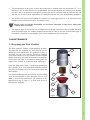
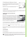
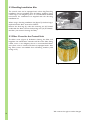
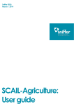
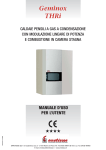
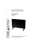
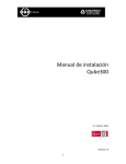
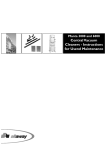
INSTRUCTIONS FOR USE AND MAINTENANCE CENTRAL VACUUM CLEANERS A 30, A 40, A 40 LCD, A 60 2 CONTENTS 1 GENERAL GUIDELINES................................................................................................................................ 4 2 INSTALLATION............................................................................................................................................... 4 2 .1 Positioning of the Central Unit................................................................................................................ 4 3 MAINTENANCE............................................................................................................................................. 5 3 .1 Emptying the Dust Canister...................................................................................................................... 5 3.2 Servicing the Filter...................................................................................................................................... 6 3.3 Cleaning Accessories................................................................................................................................... 6 4 SAFETY DEVICES........................................................................................................................................... 6 5 USEFUL TIPS.................................................................................................................................................... 7 5.1 What to Do if the Central Unit Will Not Start.................................................................................... 7 5.2 What to Do if Suction Power Has Dropped......................................................................................... 8 5.3 What to Do if the Suction Hose Is Damaged....................................................................................... 8 5.4 What to Do if the Pipe System or the Exhaust Pipe Is Blocked....................................................... 8 5.5 Details Required for Maintenance Purposes.......................................................................................... 9 6 POWER CORD............................................................................................................................................... 9 7 INSPECTING THE PIPE SYSTEM FOR TIGHTNESS............................................................................... 9 8 EC DECLARATION OF CONFORMITY FOR ELECTRICAL SAFETY............................................... 9 9 ACCESSORIES................................................................................................................................................. 9 9.1 Pre-separators.............................................................................................................................................. 9 9.2 Dust Bag Installation Kits......................................................................................................................... 10 9.3 Filter Cover for the Central Unit.......................................................................................................... 10 MAINTENANCE LOG.................................................................................................................................... 11 KEY TO SYMBOLS WARNING FURTHER INFORMATION Keep the instructions for further reference! 3 Thank you for your faith in our products! We have produced these Instructions for Use and Maintenance so as to enable you to use your central vacuum cleaning system in the best way possible. These instructions are meant for the central vacuum cleaner models A 30, A 40, A 40 LCD and A 60. Nameplate markings (type): TE-1650-..-.., TE-1750-..-.., TE-1950-..-.., VE-1750-..-.., VE-1950-..-.., V-2000-..-.. Please read the instructions carefully before using the system and follow all instructions in this manual. The detailed installation instructions for the wall inlets and parts of the piping can be found in the installation manual for the Allaway central vacuum cleaning system. You can ensure the operation, efficiency, and long service life of your central vacuum cleaning system by following all instructions and by only using original Allaway parts and supplies. Keep the stickers from the product packaging to facilitate further purchases and expansion of the system. Keep the machine out of reach of small children. The machine is not a toy. The machine should not be used by persons with reduced physical, sensory, or mental abilities. Monitor and instruct older children and persons with insufficient experience or skills in the use of the machine. 1 GENERAL GUIDELINES These central vacuum cleaners are only designed for domestic use and should only be used by one person at a time and only for cleaning normal dust and rubbish. Prior to starting up the unit for the first time, please check that the dust canister is empty and that the filter is in place. If the central unit is used for vacuuming anything other than normal dust, a suitable Allaway pre separator must be used. The wall inlets are equipped with catchers that stop large particles from entering the pipe system, and longitudinal objects are caught in the steep elbow couplings located behind the inlets. Only one wall inlet can be open at a time when the system is operational, and the covers of all other inlets must be closed. Keeping more than one inlet open at a time weakens the suction power of the system and increases the risk of blockages. 2 INSTALLATION 2.1 Positioning of the Central Unit For detailed instructions for installation, please refer to the separate instructions for installing Allaway central vacuum cleaning systems, which are supplied as standard with pipe kits PPK-44 and PPC-44 and can also be ordered separately. The instructions can also be found at our website at www.allaway. fi. Please follow local regulations for installations. The central unit is connected to a 230 V power socket protected with a slow fuse of at least 10 A or an automatic fuse of at least 16 A. 4 The temperature of the room in which the central unit is located must not drop below +5 ° C or rise above +35 °C, even while the unit is operational. The heat produced by the central unit is released into the room. It is therefore important to ensure that air can circulate freely around the unit and that the unit is not covered with textiles, for example, and that the room is adequately ventilated. The central unit must not be installed in a cupboard or other tight spaces or in an unheated room. Suitable rooms include storerooms and utility rooms. Never store or handle flammable or corrosive materials in the room where the central unit is located. The exhaust pipe of the central unit is always led outside. We recommend that a muffler be fitted onto the exhaust pipe. The muffler should be positioned as close to the end of the exhaust pipe as possible for maximum power. Mufflers must not be installed on the suction side. 3 MAINTENANCE 3.1 Emptying the Dust Canister The dust canister’s volume is approximately 20 litres. The intervals for emptying the dust canister can be established with experience. The guideline is that in domestic use the dust canister should be emptied every three months or so. The canister must be emptied before the level of dust reaches the bottom of the quick release clips. This helps to prevent dust seeping over the edges of the canister in connection with emptying it. 8 9 Undo the quick release clips (1) of the dust canister. The dust canister (5) is now suspended inside the central unit. Lift the canister from the hooks and empty the dust canister. It is recommended that the dust canister and the sealing cone be washed with a mild detergent once a year. Make a note of any maintenance you perform in the Maintenance Log on page 11 to help keep track of maintenance intervals. 7 2 6 3 4 5 1 Figure 1 5 3.2 Servicing the Filter (Figure 1) The central unit is equipped with a filter (2) that protects the turbine against dust. The filter must be intact and correctly in place. New filters can be purchased from all leading retailers and authorised Allaway service dealers. Unplug the power cord (6) from the wall socket. Remove and empty the dust canister (5). Remove the sealing cone (sealing and cone). Remove the filter cover carefully if the cover is in use. Open the fastening nut (3) below the filter and remove the filter carefully. Clean the filter by brushing it carefully. Replace the filter with a new one if suction power has diminished or the filter is damaged. Do not allow dirt to get inside the filter. Never clean the filter with water, compressed air or by beating it. Remove any loose dust from the filter chamber. Replace the filter and fastening nut (3). Tighten the fastening nut by hand. Clean the sealing surfaces of the sealing cone carefully. Replace the sealing cone. Replace the dust canister. Plug the power cord into the wall socket. We recommend that the filter is replaced at least every 3 years. If a dust bag is used, only replace the filter when necessary. 3.3 Cleaning Accessories Tell children how to use the system and supervise them while they do so! The speed and vacuum power of the airflow in the suction hose and the nozzles are so great that they could, if used carelessly, cause damage to eyes and ears, for example. The cleaning accessories are subject to wear and tear, and they must be replaced when necessary. Their life can be extended significantly by cleaning them from accumulated dirt after use and by storing them appropriately. After vacuuming, detach the telescopic wand and the nozzles from the handle, and store them in the nozzle holder with the brush of the floor/carpet nozzle retracted. Avoid storing the cleaning accessories in direct sunlight, as long-term exposure to UV light makes the plastic parts, and especially the hose, go brittle, thus shortening their serviceable life. Store the hose in the suction hose stand. Separate instructions for use and maintenance are supplied with cleaning sets that are sold individually. 4 SAFETY DEVICES The central units are equipped with safety devices that stop the unit in case of a malfunction. If the issue causing the safety devices to trip is not resolved and the system is used regardless of the malfunction, damage to the system may occur. This is why the safety devices should not be considered as indicators of when the dust canister requires emptying or when the filter needs servicing, or otherwise as means of enabling the system to be used or installed in a manner contradictory to the instructions. The central unit is equipped with an overload protector that stops the unit in case of an electrical overload or malfunction. The overload protector cannot be reset and must be replaced by a qualified electrical engineer. In connection with replacing the overload protector, the cause of tripping must be investigated and resolved along with any other faults. 6 The overheat protector of the turbine is located inside the unit and it stops the central unit in case the turbine overheats. Wait until the turbine has cooled down and the overheat protector has been reset (approximately 10-15 min.). Find out why the overheat protector has tripped and eliminate the cause (e.g. full dust canister, blocked filter, blockage in the pipe system, wall inlet, exhaust pipe, cleaning accessories or the blow-out grating). If whatever it is that causes the safety devices to trip is not resolved and the system is used regardless of the malfunction, damage to the system may occur. There are no parts for the user to maintain inside the central unit’s motor housing (figure 1; components 8 and 9). We recommend that the need for maintenance and replacement for the electric motor’s turbine and other parts inside the motor housing are estimated by an authorised Allaway service dealer after approx. 600 hours of use. This corresponds to approx. 8 years when the device is used an average of an hour and a half per week. 5 USEFUL TIPS 5.1 What to Do if the Central Unit Will Not Start Check that the 230V power supply is intact. Check whether the central unit can be started from the other wall inlets. Check that the low voltage wires (figure 1; 7) are connected correctly to the central unit. Check whether the central unit can be started via the low voltage connector (figure 1; 7) of the central unit by closing the start circuit with a piece of metal wire (as shown in figure 2 depending on the central unit model). In case of suction hoses that are equipped with a handle start mechanism, check that the start circuit inside the hose is intact. If the central unit can be started by connecting the contact pins with a piece of metal wire, for example, but not with the control switch on the handle, the fault is either in the hose or in the switch. Figure 2 If the central unit can be started via the low voltage connector but not by opening a wall inlet, check that the low voltage wires are connected to the central unit and the wall inlets and that there are no breaks in the wires. Check whether the overheat protector inside the unit has tripped as a result of the turbine overheating. If this is the case, wait for the turbine to cool down sufficiently (approximately 15 minutes) and then check that the filter is not blocked, the dust canister or the dust bag are not full, and that there are no blockages in the wall inlets, the exhaust pipe or the cleaning accessories. Check whether the overload protector has tripped. If this is the case, the start relay of the central unit will make a clicking sound but the motor will not start; contact an authorised Allaway service dealer. 7 5.2 What to Do if Suction Power Has Dropped Check that all other wall inlets are closed and that they do not leak. Check that there are no objects inside the wall inlet that could obstruct flow. Check that the suction hose is intact and that no objects that could obstruct flow are lodged in it. Check that the dust canister is correctly in place and that the sealing materials of the dust canister are clean and intact. Check that the dust canister is not full or that the dust bag does not require replacing. Check that the filter is in good condition. Check that the pipe system is airtight (see section INSPECTING THE PIPE SYSTEM FOR TIGHTNESS). 5.3 What to Do if the Suction Hose Is Damaged Cut the damaged section out and reconnect the hose using an extension coupling muff (accessory). If the hose breaks near the hose coupling muff or the handle, detach the muff or handle, cut out the damaged section and twist the hose coupling muff or handle back onto the hose (the components of the hose have a left-handed thread). In suction hoses equipped with a handle start mechanism, the start circuit wires are built into the hose. The hose cannot be shortened or extended. In case of damage to the hose, contact an authorised Allaway service dealer. 5.4 What to Do if the Pipe System or the Exhaust Pipe Is Blocked 8 Empty the dust canister and clean (replace) the filter. Locate the blockage by sucking strips of kitchen paper through the wall inlets. If the strips of paper end up in the dust canister, that stretch of the pipe system is clear. Once you have located the blockage, disconnect the central unit and check that there are no blockages in the coupling hoses. Then use the suction hose to connect the suction-side coupling hose to a wall inlet along the blocked stretch (or to the wall inlet closest to the blockage, if the blockage is in the frame pipe). Start the central unit (see figure 2/3 for starting the central unit with the help of a piece of metal wire), and go to where the central unit is usually mounted. Block and unblock the suction pipe opening with your hand to send vacuum shocks to the blocked pipe. If the blockage has not become dislodged within 10-15 seconds, disconnect the central unit from the wall inlet to allow the turbine to get some air in between and to stop it from overheating. Repeat the process after approximately one minute. If the worth of the a pipe Never use overpressure, such as compressed air, to try unblocking the pipe system, as overpressure will cause the pipe joints to become undone. You can also try dislodging the blockage by inserting a tension spring into the pipe system, taking care not to damage the pipe joints. If none of the measures described above are successful in unblocking the pipe system, contact an authorised Allaway service dealer. blockage cannot be dislodged through suction and you are able to pinpoint its location, it is examining whether the pipe system is easily accessible without having to dismantle too much structure. If the pipe system is accessible, the blockage can usually be removed by opening joint. 5.5 Details Required for Maintenance Purposes Prior to contacting an authorised Allaway service cleaner, note down the type and serial number (N:o) of your central unit, marked on the nameplate (on the external surface of the central unit, on the side of the turbine housing). IPX2 Always keep the unit in its normal upright position during transportation and take care not to drop it or to make it subject to blows. Figure 4 6 POWER CORD If the power cord of the central unit has been damaged, it must be replaced with a special cord compatible with the model of central unit in question and supplied by the manufacturer. Power cords can be purchased from authorised Allaway service dealers. 7 INSPECTING THE PIPE SYSTEM FOR TIGHTNESS Start the central unit with all wall inlets closed by connecting the start circuit via the low voltage connector using a piece of metal wire. If air is still escaping from the exhaust pipe after approximately 10 seconds, there is a leak in the pipe system. The leak must be located and repaired. Do not run the unit for more than 20 seconds with all of the wall inlets closed. If the installation is completely airtight, the turbine will not receive any air, therefore overheating and possibly incurring damage. The bypass valve must be blocked for the duration of the inspection using a piece of cardboard, for example (figure 4). Figure 4 8 EC DECLARATION OF CONFORMITY FOR ELECTRICAL SAFETY Allaway Oy, Kangasvuorentie 32, 40340 Jyväskylä, Finland, hereby declares that Central Vacuum Cleaners Type: TE-1650-..-.., TE-1750-..-.., TE-1950-..-.., VE-1750-..-.., VE-1950-..-.., V-2000..-.. have been manufactured in accordance with the relevant harmonised standards and fulfils the essential requirements of the Low Voltage Directive (2006/95/EC) and the Electromagnetic Compatibility Directive (2004/108/EC). 9 ACCESSORIES 9.1 Pre-separators The EE-20 is designed for vacuuming liquids, sand and coarse rubbish. If the pre-separator is equipped with a dust bag, the EE-20 also enables the vacuuming of cooled-down ashes and fine dry dust. Sticky substances and shards of glass may damage the pipe system. The system must not be used for vacuuming liquids or substances other than normal dust unless a suitable Allaway-pre-separator is used. 9 9.2 Dust Bag Installation Kits The central units can be equipped with a dust bag. Dust bag installation kits are available from all leading retailers. Using a dust bag is not obligatory, but it is recommended. Detailed instructions for installation are supplied with the dust bag installation kit. When using a dust bag installation kit (figure 5), the dust bag is replaced and the filter serviced as follows: Remove the dust bag (9), undo the mounting nut (6) located underneath the filter, remove the dust bag rest (10) and detach the filter (see section Servicing the Filter). 10 6 9 Figure 5 9.3 Filter Cover for the Central Unit The filter cover (figure 6) facilitates cleaning the filter and lengthens the maintenance intervals and life of the filter. Using a filter cover is not obligatory, but it is recommended. Never use a filter cover in central units that are equipped with a dust bag. Filter covers are available from all leading retailers (sold in bags of 5). Figure 6 10 We reserve the right to make changes. MAINTENANCE LOG Type ____________ Dust Canister Emptied or Dust Bag Replaced Filter Cleaned No. ____________ First Used on (date) ____________ Filter Replaced Dust Canister Emptied or Dust Bag Replaced Filter Cleaned Filter Replaced 11 Customer service Austria Provit Handels- u.Engineering GmbH, Laaberbachstrasse 18, A-4600 Wels phone: 43-7242-55 677, [email protected], www.provit.at Cyprus Domex Trading Co.Ltd, CTC House,Athalassa P.O.Box 21744, 1589 Nicosia phone: 357-22-74 03 40, [email protected], www.ctcgroup.com Denmark BHC Teknik, Brystrupvej 4, Hellevad, 6230 Rødekro phone: 45-7466 9613, [email protected], www.bhc-teknik.dk Estonia Rautakesko AS, Tähetorni 100a, 11625 Tallinn phone: 625 7501, [email protected], www.rautakesko.ee Finland Allaway Oy, PL 3, 40351 Jyväskylä phone: +358 (0)14 410 1600, [email protected], www.allaway.com Germany Heinemann GmbH, Von-Eichendorff-Str. 59 A, 86911 Diessen am Ammersee phone: 49-88-07 9466 0, [email protected], www.heinemann-gmbh.de Italy Erretiesse S.p.A., Via Ungheresca Sud, 3, I-31010 Mareno Di Piave (TV) phone: 39-0438-498910, [email protected], www.erretiesse.it Latvia Aero Clean Studio Sia, Atlasa 7a, Riga, Riga, LV-1026 phone: +371 67 88 69 24, [email protected], www.allaway.lv Poland WPH Wirexim Sp. z o.o., ul.Jugoslowiańska 13, PL- 60-301 Poznań phone: 48-61-6620 777, [email protected], www.allaway.pl Rumania SC DOB A&A SRL, Str. Cezar Bolliac Nr.2, RO- 620167 Focsani phone: 40-727 731 551, [email protected], www.dobservicii.ro Spain La Casa Domotica SL, Ctra Villalba 15, 28411 Moralzarzal phone: +34 902 537 028, [email protected], www.thedomotichouse.es Sweden CDS Centraldammsugare AB, Företagsgallén 8, 18440 Åkersberga phone: 46-8-594 106 00, [email protected], www.allaway.se Switzerland Riesen Reinlufttechnik GmbH, Allmeindstrasse 23, CH-8716 Schmerikon phone: 41-55-283 29 29, [email protected], www.allaway.ch The Netherlands Hugro Technics vof, Lage Brink 93, NL-07317 BD Apeldoorn phone: 31-55-521 4402, [email protected], www.allaway.nl UK and Ireland Bedrock Power Ltd, 6 Clady Road, Portglenone, BT44 8JX phone: 028 2582 1236, [email protected], www.bedrockpower.com JYVÄSKYLÄ, FINLAND www.allaway.com 13759 en Rev02 06/2010