1
AX2200S/AX1250S/AX1240S Software Manual
Operation Command Reference
For Version 2.4
AX1240S-S004X-60
Relevant products
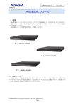
This manual applies to the models in the AX2200S, AX1250S, and AX1240S series of switches. The manual
describes the functionality of software version 2.4 for the AX2200S, AX1250S, and AX1240S switches that is
supported by the software OS-LT4, OS-LT3, OS-LT2, and optional licenses.
Export restrictions
In the event that any or all ALAXALA products (including technologies, programs and services) described or
contained herein are controlled under any of applicable export control laws and regulations (including the Foreign
Exchange and Foreign Trade Law of Japan and United States export control laws and regulations), such products
shall not be exported without obtaining the required export licenses from the authorities concerned in accordance
with the above laws.
Trademarks
−
−
−
−
−
−
−
Ethernet is a registered trademark of Xerox Corporation.
Microsoft is either a registered trademark or trademark of Microsoft Corporation in the United States and other
countries.
Windows is a registered trademark of Microsoft Corporation in the United States and other countries.
RSA and RSA SecurID are trademarks or registered trademarks of RSA Security Inc. in the United States and
other countries.
Wake on LAN is a registered trademark of IBM Corporation.
MagicPacket is a registered trademark of Advanced Micro Devices, Inc.
Other company and product names in this document are trademarks or registered trademarks of their respective
owners.
Reading and storing this manual
Before you use the equipment, carefully read the manual and make sure that you understand all safety precautions.
After reading the manual, keep it in a convenient place for easy reference.
Notes
Information in this document is subject to change without notice.
Editions history
July 2012 (Edition 7) AX1240S-S004X-60
Copyright
All Rights Reserved, Copyright(C),2008, 2012, ALAXALA Networks, Corp.
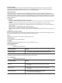
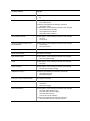
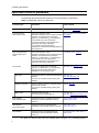
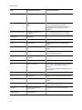
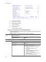
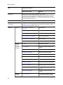
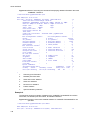
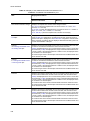
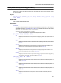
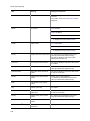
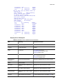
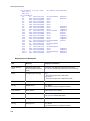
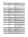
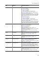
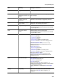
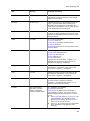
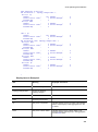
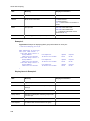
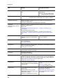
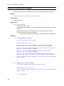
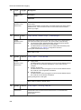
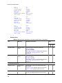
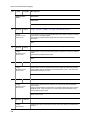
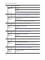
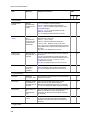
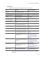
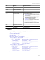
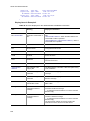
History of Amendments
Ver. 2.4 (Edition 7)
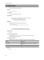
Summary of amendments
Location and title
Changes
Addition of series
A description of the AX2200S series switches was added.
In addition to the above changes, minor editorial corrections were made.
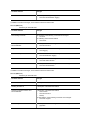
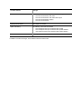
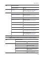
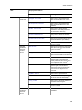
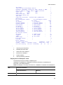
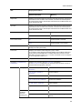
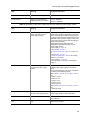
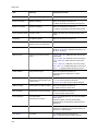
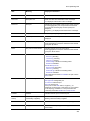
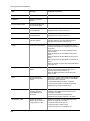
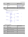
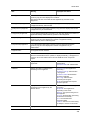
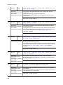
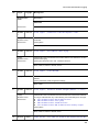
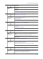
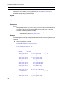
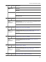
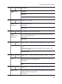
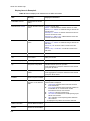
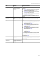
Ver. 2.3 (Edition 6)
Summary of amendments
Location and title
Changes
Ethernet
The descriptions of the following command were changed:
show port
Ring Protocol
The descriptions of the following command were changed:
show axrp
Web Authentication
The list of operation log messages was modified:
show web-authentication logging
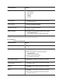
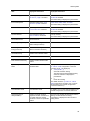
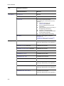
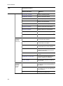
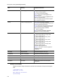
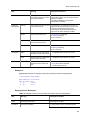
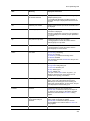
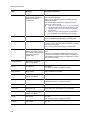
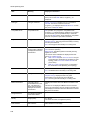
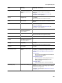
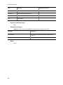
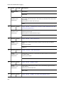
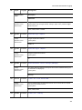
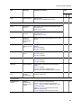
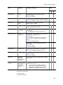
Location and title
Changes
MAC-based Authentication
The list of operation log messages was modified:
show mac-authentication logging
In addition to the above changes, minor editorial corrections were made.
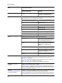
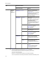
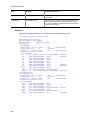
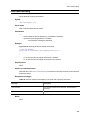
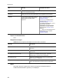
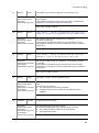
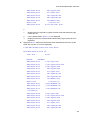
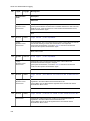
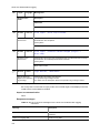
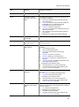
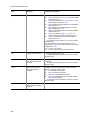
Ver. 2.3 (Edition 5)
Summary of amendments
Location and title
Changes
Time Settings and NTP
The example of the following command was changed:
set clock
The following command was added:
show clock
Checking Software Versions and
Device Statuses
The descriptions of the following command were changed:
show environment
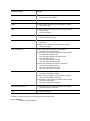
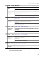
Log
A parameter was added to the following command:
show logging
Common to Layer 2 Authentication
A parameter was added to the following command:
show authentication logging
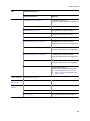
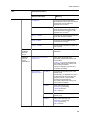
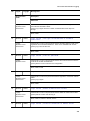
Web Authentication
The descriptions of the following command were changed:
show web-authentication
MAC-based Authentication
The descriptions of the following command were changed:
show mac-authentication
In addition to the above changes, minor editorial corrections were made.
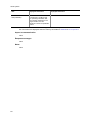
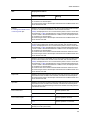
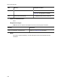
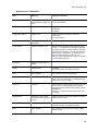
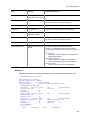
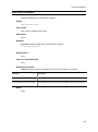
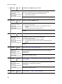
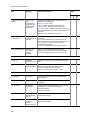
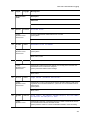
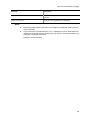
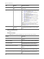
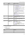
Ver. 2.2 (Edition 4)
Summary of amendments
Location and title
Changes
Addition of series
A description of AX1250S was added.
Reading the Manual
A description of AX1250S was added.
Checking Software Versions and
Device Statuses
A description of AX1250S was added.
show version
show environment
backup
The descriptions of the following command were changed:
show tech-support
Software update
The descriptions of the following command were changed:
ppupdate
Location and title
Changes
Ethernet
The descriptions of the following commands were changed:
show interfaces
clear counters
show port
activate
inactivate
Link aggregation
The descriptions of the following command were changed:
show channel-group
DHCP snooping
A description of AX1250S was added.
show ip arp inspection statistics
IPv4, ARP, and ICMP
A description of AX1250S was added.
show ip interface
Uplink redundancy
The descriptions of the following commands were changed:
show switchport backup
show switchport backup mac-address-table update
In addition to the above changes, minor editorial corrections were made.
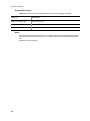
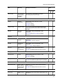
Ver. 2.2 (Edition 3)
Summary of amendments
Location and title
Changes
Configurations and File Operations
Parameters were added to the following command:
copy
Login Security and RADIUS
The descriptions of the following command were changed:
show radius-server
Parameters were added to the following commands:
clear radius-server
show radius-server statistics
The following command was deleted:
show radius-server summary
Time Settings and NTP
The input format of the following command was changed:
set clock
Checking Software Versions and
Device Statuses
The descriptions of the following command were changed:
show environment
Ethernet
The descriptions of the following command were changed:
show port
VLAN
The descriptions of the following command were changed:
show vlan
The input format of the following command was changed:
show vlan mac-vlan
Location and title
Changes
Spanning Tree Protocol
The descriptions of the following command were changed:
show spanning-tree statistics
Ring Protocol
This chapter was added.
Filters
The input format of the following command was changed:
show access-filter
QoS
The input formats of the following commands were changed:
show qos-flow
show qos queueing
Common to Layer 2 Authentication
The descriptions of the following command were changed:
show authentication logging
IEEE802.1X
The descriptions of the following command were changed:
show dot1x
The display of the operation log message was changed:
show dot1x logging
Web Authentication
The list of operation log messages was modified:
show web-authentication logging
The descriptions of the following commands were changed:
show web-authentication login
show web-authentication login select-option
show web-authentication
show web-authentication statistics
show web-authentication html-files
Parameters were added to the following commands:
set web-authentication html-files
store web-authentication html-files
clear web-authentication html-files
MAC-based Authentication
The list of operation log messages was modified:
show mac-authentication logging
The input format of the following command was changed:
clear mac-authentication auth-state
The descriptions of the following commands were changed:
show mac-authentication
show mac-authentication statistics
Multistep authentication
The descriptions of the following command were changed:
show authentication multi-step
CFM
This chapter was added.
In addition to the above changes, minor editorial corrections were made.
Ver. 2.1 (Edition 2)
Summary of amendments
Location and title
Changes
Terminals and Remote Operations
The following command was added:
ftp
Login Security and RADIUS
The following command was added:
show radius-server
Parameters were added to the following command:
clear radius-server
The descriptions of the following commands were changed:
show radius-server summary
show radius-server statistics
clear radius-server statistics
Time Settings and NTP
The descriptions of the following commands were changed:
set clock
set clock ntp
Checking Software Versions and
Device Statuses
The descriptions of the following commands were changed:
show system
show environment
Power Saving Functionality
This chapter was added.
Resource Information
This chapter was added.
MAC Address Table
The descriptions of the following command were changed:
show mac-address-table
VLAN
The descriptions of the following command were changed:
show vlan
DHCP snooping
The descriptions of the following command were changed:
show ip dhcp snooping binding
IGMP/MLD snooping
Parameters were added to the following commands:
show igmp-snooping
show mld-snooping
Common to Layer 2 Authentication
This chapter was added.
IEEE802.1X
The descriptions of the following commands were changed:
show dot1x
show dot1x logging
Web Authentication
The descriptions of the following commands were changed:
show web-authentication login
show web-authentication logging
show web-authentication
show ip dhcp server statistics
Parameters were added to the following command:
show web-authentication login select-option
Location and title
Changes
MAC-based Authentication
The descriptions of the following commands were changed:
show mac-authentication auth-state
show mac-authentication auth-state select-option
show mac-authentication logging
show mac-authentication
Multistep authentication
This chapter was added.
Uplink redundancy
The following commands were added:
show switchport backup mac-address-table update
show switchport backup mac-address-table update statistics
clear switchport backup mac-address-table update statistics
Storm Control
This chapter was added.
In addition to the above changes, minor editorial corrections were made.
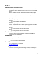
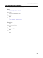
Preface
Applicable products and software versions
This manual applies to the AX2200S, AX1250S, and AX1240S series of switches. The
manual describes the functionality of software version 2.4 for the AX2200S, AX1250S, and
AX1240S series switches supported by the OS-LT4, OS-LT3, and OS-LT2 and optional
licenses.
Before you operate the equipment, carefully read the manual and make sure that you
understand all instructions and cautionary notes. After reading the manual, keep it in a
convenient place for easy reference.
Unless otherwise noted, this manual describes the functionality applicable commonly to
AX2200S, AX1250S, and AX1240S series switches. The functionalities specific to each
model are indicated as follows:
[AX2200S]:
The description applies to the AX2200S Switch.
[AX1250S]:
The description applies to the AX1250S Switch.
[AX1240S]:
The description applies to the AX1240S Switch.
In addition, unless otherwise noted, this manual describes the functionality applicable to
OS-LT4, OS-LT3, and OS-LT2. The functionality supported by option licenses are indicated
as follows:
[OP-WOL]:
The description applies to the OP-WOL optional license.
[OP-OTP]:
The description applies to the OP-OTP optional license.
Corrections to the manual
Corrections to this manual might be contained in the Release Notes and Manual
Corrections that come with the software.
Intended readers
This manual is intended for system administrators who wish to configure and operate a
network system that uses the Switch.
Readers must have an understanding of the following:
The basics of network system management
Manual URL
You can view this manual on our website at:
http://www.alaxala.com/en/
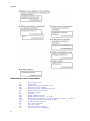
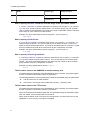
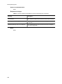
Reading sequence of the manuals
The following shows the manuals you need to consult according to your requirements
determined from the following workflow for installing, setting up, and starting regular
operation of the Switch.
I
Preface
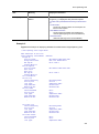
Abbreviations used in the manual
AC
ACK
ADSL
ALG
ANSI
ARP
AS
AUX
BGP
BGP4
BGP4+
bit/s
BPDU
BRI
CC
CDP
CFM
II
Alternating Current
ACKnowledge
Asymmetric Digital Subscriber Line
Application Level Gateway
American National Standards Institute
Address Resolution Protocol
Autonomous System
Auxiliary
Border Gateway Protocol
Border Gateway Protocol - version 4
Multiprotocol Extensions for Border Gateway Protocol - version 4
Bits per second (can also appear as bps)
Bridge Protocol Data Unit
Basic Rate Interface
Continuity Check
Cisco Discovery Protocol
Connectivity Fault Management
Preface
CIDR
CIR
CIST
CLNP
CLNS
CONS
CRC
CSMA/CD
CSNP
CST
DA
DC
DCE
DHCP
DIS
DNS
DR
DSAP
DSCP
DTE
DVMRP
E-Mail
EAP
EAPOL
EFM
ES
FAN
FCS
FDB
FQDN
FTTH
GBIC
GSRP
HMAC
IANA
ICMP
ICMPv6
ID
IEC
IEEE
IETF
IGMP
IP
IPCP
IPv4
IPv6
IPV6CP
IPX
ISO
ISP
IST
L2LD
LAN
LCP
LED
LLC
LLDP
LLQ+3WFQ
LSP
LSP
LSR
MA
MAC
Classless Inter-Domain Routing
Committed Information Rate
Common and Internal Spanning Tree
ConnectionLess Network Protocol
ConnectionLess Network System
Connection Oriented Network System
Cyclic Redundancy Check
Carrier Sense Multiple Access with Collision Detection
Complete Sequence Numbers PDU
Common Spanning Tree
Destination Address
Direct Current
Data Circuit terminating Equipment
Dynamic Host Configuration Protocol
Draft International Standard/Designated Intermediate System
Domain Name System
Designated Router
Destination Service Access Point
Differentiated Services Code Point
Data Terminal Equipment
Distance Vector Multicast Routing Protocol
Electronic Mail
Extensible Authentication Protocol
EAP Over LAN
Ethernet in the First Mile
End System
Fan Unit
Frame Check Sequence
Filtering DataBase
Fully Qualified Domain Name
Fiber To The Home
GigaBit Interface Converter
Gigabit Switch Redundancy Protocol
Keyed-Hashing for Message Authentication
Internet Assigned Numbers Authority
Internet Control Message Protocol
Internet Control Message Protocol version 6
Identifier
International Electrotechnical Commission
Institute of Electrical and Electronics Engineers, Inc.
the Internet Engineering Task Force
Internet Group Management Protocol
Internet Protocol
IP Control Protocol
Internet Protocol version 4
Internet Protocol version 6
IP Version 6 Control Protocol
Internetwork Packet Exchange
International Organization for Standardization
Internet Service Provider
Internal Spanning Tree
Layer 2 Loop Detection
Local Area Network
Link Control Protocol
Light Emitting Diode
Logical Link Control
Link Layer Discovery Protocol
Low Latency Queueing + 3 Weighted Fair Queueing
Label Switched Path
Link State PDU
Label Switched Router
Maintenance Association
Media Access Control
III
Preface
MC
MD5
MDI
MDI-X
MEP
MIB
MIP
MRU
MSTI
MSTP
MTU
NAK
NAS
NAT
NCP
NDP
NET
NLA ID
NPDU
NSAP
NSSA
NTP
OADP
OAM
OSPF
OUI
packet/s
PAD
PAE
PC
PCI
PDU
PICS
PID
PIM
PIM-DM
PIM-SM
PIM-SSM
PoE
PRI
PS
PSNP
QoS
RA
RADIUS
RDI
REJ
RFC
RIP
RIPng
RMON
RPF
RQ
RSTP
SA
SD
SDH
SDU
SEL
SFD
SFP
SMTP
SNAP
IV
Memory Card
Message Digest 5
Medium Dependent Interface
Medium Dependent Interface crossover
Maintenance association End Point
Management Information Base
Maintenance domain Intermediate Point
Maximum Receive Unit
Multiple Spanning Tree Instance
Multiple Spanning Tree Protocol
Maximum Transfer Unit
Not AcKnowledge
Network Access Server
Network Address Translation
Network Control Protocol
Neighbor Discovery Protocol
Network Entity Title
Next-Level Aggregation Identifier
Network Protocol Data Unit
Network Service Access Point
Not So Stubby Area
Network Time Protocol
Octpower Auto Discovery Protocol
Operations, Administration, and Maintenance
Open Shortest Path First
Organizationally Unique Identifier
packets per second (can also appear as pps)
PADding
Port Access Entity
Personal Computer
Protocol Control Information
Protocol Data Unit
Protocol Implementation Conformance Statement
Protocol IDentifier
Protocol Independent Multicast
Protocol Independent Multicast-Dense Mode
Protocol Independent Multicast-Sparse Mode
Protocol Independent Multicast-Source Specific Multicast
Power over Ethernet
Primary Rate Interface
Power Supply
Partial Sequence Numbers PDU
Quality of Service
Router Advertisement
Remote Authentication Dial In User Service
Remote Defect Indication
REJect
Request For Comments
Routing Information Protocol
Routing Information Protocol next generation
Remote Network Monitoring MIB
Reverse Path Forwarding
ReQuest
Rapid Spanning Tree Protocol
Source Address
Secure Digital
Synchronous Digital Hierarchy
Service Data Unit
NSAP SELector
Start Frame Delimiter
Small Form factor Pluggable
Simple Mail Transfer Protocol
Sub-Network Access Protocol
Preface
SNMP
SNP
SNPA
SPF
SSAP
STP
TA
TACACS+
TCP/IP
TLA ID
TLV
TOS
TPID
TTL
UDLD
UDP
ULR
UPC
UPC-RED
VAA
VLAN
VRRP
WAN
WDM
WFQ
WRED
WS
WWW
XFP
Simple Network Management Protocol
Sequence Numbers PDU
Subnetwork Point of Attachment
Shortest Path First
Source Service Access Point
Spanning Tree Protocol
Terminal Adapter
Terminal Access Controller Access Control System Plus
Transmission Control Protocol/Internet Protocol
Top-Level Aggregation Identifier
Type, Length, and Value
Type Of Service
Tag Protocol Identifier
Time To Live
Uni-Directional Link Detection
User Datagram Protocol
Uplink Redundant
Usage Parameter Control
Usage Parameter Control - Random Early Detection
VLAN Access Agent
Virtual LAN
Virtual Router Redundancy Protocol
Wide Area Network
Wavelength Division Multiplexing
Weighted Fair Queueing
Weighted Random Early Detection
Work Station
World-Wide Web
10 gigabit small Form factor Pluggable
Conventions: KB, MB, GB, and TB
This manual uses the following conventions: 1 KB (kilobyte) is 1024 bytes.1 MB
2
3
4
(megabyte) is 1024 bytes.1 GB (gigabyte) is 1024 bytes.1 TB (terabyte) is 1024 bytes.
Conventions: The terms "Switch" and "switch"
The term Switch (upper-case "S") is an abbreviation for any or all of the following models:
AX2200S series switch
AX1250S series switch
AX1240S series switch
The term switch (lower-case "s") might refer to a Switch, another type of switch from the
current vendor, or a switch from another vendor. The context decides the meaning.
V
Preface
VI
Contents
Preface .............................................................................................................................................. I
Part 1: Reading the Manual ............................................................................................................ 1
1. Reading the Manual .................................................................................................................... 1
Command description format .................................................................................................. 2
Specifiable values for parameters ........................................................................................... 4
List of character codes ............................................................................................................ 7
Messages displayed by the entry-error detection functionality ............................................... 8
Part 2: Basic Operation ................................................................................................................... 9
2. Switching the Command Input Mode........................................................................................ 9
enable ...................................................................................................................................... 10
disable ..................................................................................................................................... 11
exit ......................................................................................................................................... 12
logout ....................................................................................................................................... 13
configure .................................................................................................................................. 14
3. Terminals and Remote Operations ........................................................................................... 15
set exec-timeout ...................................................................................................................... 16
set terminal pager .................................................................................................................... 18
telnet ........................................................................................................................................ 19
ftp ......................................................................................................................................... 21
line console speed................................................................................................................... 27
trace-monitor ........................................................................................................................... 29
4. Configurations and File Operations .......................................................................................... 31
show running-config ................................................................................................................ 32
show startup-config ................................................................................................................. 33
copy ......................................................................................................................................... 34
erase startup-config ................................................................................................................. 38
rename .................................................................................................................................... 39
del ......................................................................................................................................... 41
mkdir ........................................................................................................................................ 43
rmdir ........................................................................................................................................ 45
5. Login Security and RADIUS ....................................................................................................... 47
password ................................................................................................................................. 48
clear password ........................................................................................................................ 50
show sessions(who) ................................................................................................................ 52
rename user ............................................................................................................................ 53
show radius-server .................................................................................................................. 54
clear radius-server................................................................................................................... 57
show radius-server statistics ................................................................................................... 59
clear radius-server statistics .................................................................................................... 63
6. Time Settings and NTP ............................................................................................................... 65
set clock .................................................................................................................................. 66
show clock ............................................................................................................................... 68
set clock ntp ............................................................................................................................ 69
show ntp-client ........................................................................................................................ 70
Part 3: Operating Devices ............................................................................................................... 73
7. Checking Software Versions and Device Statuses.................................................................. 73
show version ........................................................................................................................... 74
show system ............................................................................................................................ 76
i
Contents
show environment ................................................................................................................... 81
reload ...................................................................................................................................... 86
show tech-support ................................................................................................................... 88
backup ..................................................................................................................................... 90
restore ..................................................................................................................................... 93
8. Power Saving Functionality ....................................................................................................... 95
set power-control schedule ..................................................................................................... 96
show power-control port .......................................................................................................... 97
show power-control schedule .................................................................................................. 99
9. Checking Internal Memory and Memory Cards ....................................................................... 101
format mc ................................................................................................................................ 102
format flash .............................................................................................................................. 104
show mc .................................................................................................................................. 106
show mc-file ............................................................................................................................ 108
show ramdisk .......................................................................................................................... 110
show ramdisk-file..................................................................................................................... 111
10. Log ............................................................................................................................................. 113
show logging ........................................................................................................................... 114
clear logging ............................................................................................................................ 117
show critical-logging ................................................................................................................ 118
show critical-logging summary ................................................................................................ 121
clear critical-logging................................................................................................................. 123
11. Software Update ....................................................................................................................... 125
ppupdate ................................................................................................................................. 126
12. Resource Information .............................................................................................................. 129
show cpu ................................................................................................................................. 130
show memory summary .......................................................................................................... 133
Part 4: Network Interfaces .............................................................................................................. 135
13. Ethernet ..................................................................................................................................... 135
show interfaces ....................................................................................................................... 136
clear counters .......................................................................................................................... 156
show port ................................................................................................................................. 158
activate .................................................................................................................................... 167
inactivate ................................................................................................................................. 169
show power inline [AX2200S][AX1240S] ................................................................................ 171
activate power inline [AX2200S][AX1240S] ............................................................................ 178
inactivate power inline [AX2200S][AX1240S] ......................................................................... 179
14. Link Aggregation ...................................................................................................................... 181
show channel-group ................................................................................................................ 182
show channel-group statistics ................................................................................................. 193
clear channel-group statistics lacp .......................................................................................... 199
Part 5: Layer 2 Switching ................................................................................................................ 201
15. MAC Address Table .................................................................................................................. 201
show mac-address-table ......................................................................................................... 202
clear mac-address-table .......................................................................................................... 206
16. VLANs ........................................................................................................................................ 207
show vlan ................................................................................................................................ 208
show vlan mac-vlan ................................................................................................................. 218
17. Spanning Tree Protocols ......................................................................................................... 221
show spanning-tree ................................................................................................................. 222
ii
Contents
show spanning-tree statistics .................................................................................................. 251
clear spanning-tree statistics ................................................................................................... 258
clear spanning-tree detected-protocol..................................................................................... 259
show spanning-tree port-count ................................................................................................ 261
18. Ring Protocol ............................................................................................................................ 265
show axrp ................................................................................................................................ 266
19. DHCP Snooping ........................................................................................................................ 271
show ip dhcp snooping ............................................................................................................ 272
show ip dhcp snooping binding ............................................................................................... 274
clear ip dhcp snooping binding ................................................................................................ 277
show ip dhcp snooping statistics ............................................................................................. 279
clear ip dhcp snooping statistics ............................................................................................. 281
show ip arp inspection statistics .............................................................................................. 282
clear ip arp inspection statistics .............................................................................................. 284
20. IGMP/MLD Snooping ................................................................................................................ 285
show igmp-snooping ............................................................................................................... 286
clear igmp-snooping ................................................................................................................ 292
show mld-snooping ................................................................................................................. 293
clear mld-snooping .................................................................................................................. 299
Part 6: Forwarding IPv4 Packets .................................................................................................... 301
21. IPv4, ARP, and ICMP ................................................................................................................. 301
show ip interface ..................................................................................................................... 302
show ip arp .............................................................................................................................. 306
show ip route ........................................................................................................................... 308
ping ......................................................................................................................................... 310
traceroute ................................................................................................................................ 312
Part 7: Filters .................................................................................................................................... 315
22. Filters ......................................................................................................................................... 315
show access-filter .................................................................................................................... 316
clear access-filter .................................................................................................................... 319
Part 8: QoS ....................................................................................................................................... 321
23. QoS ............................................................................................................................................ 321
show qos-flow.......................................................................................................................... 322
clear qos-flow .......................................................................................................................... 325
show qos queueing ................................................................................................................. 326
clear qos queueing .................................................................................................................. 330
Part 9: Layer 2 Authentication ........................................................................................................ 331
24. Common to Layer 2 Authentication ........................................................................................ 331
show authentication fail-list ..................................................................................................... 332
clear authentication fail-list ...................................................................................................... 334
show authentication logging .................................................................................................... 335
clear authentication logging .................................................................................................... 337
25. IEEE802.1X ................................................................................................................................ 339
show dot1x statistics ............................................................................................................... 340
show dot1x .............................................................................................................................. 345
clear dot1x statistics ................................................................................................................ 351
clear dot1x auth-state .............................................................................................................. 352
reauthenticate dot1x ................................................................................................................ 354
show dot1x logging.................................................................................................................. 356
clear dot1x logging .................................................................................................................. 367
iii
Contents
26. Web Authentication .................................................................................................................. 369
set web-authentication user .................................................................................................... 370
set web-authentication passwd ............................................................................................... 372
set web-authentication vlan ..................................................................................................... 374
remove web-authentication user ............................................................................................. 375
show web-authentication user ................................................................................................. 377
show web-authentication login ................................................................................................ 379
show web-authentication login select-option .......................................................................... 382
show web-authentication login summary ................................................................................ 387
show web-authentication logging ............................................................................................ 390
clear web-authentication logging ............................................................................................. 405
show web-authentication ......................................................................................................... 406
show web-authentication statistics .......................................................................................... 414
clear web-authentication statistics .......................................................................................... 416
commit web-authentication ..................................................................................................... 417
store web-authentication ......................................................................................................... 419
load web-authentication .......................................................................................................... 421
clear web-authentication auth-state ........................................................................................ 423
set web-authentication html-files ............................................................................................. 425
store web-authentication html-files.......................................................................................... 428
show web-authentication html-files ......................................................................................... 430
clear web-authentication html-files .......................................................................................... 433
show ip dhcp binding ............................................................................................................... 435
clear ip dhcp binding ............................................................................................................... 437
show ip dhcp conflict ............................................................................................................... 438
clear ip dhcp conflict ................................................................................................................ 440
show ip dhcp server statistics.................................................................................................. 441
clear ip dhcp server statistics .................................................................................................. 443
27. MAC-based Authentication ...................................................................................................... 445
show mac-authentication auth-state ....................................................................................... 446
clear mac-authentication auth-state ........................................................................................ 449
show mac-authentication auth-state select-option .................................................................. 451
show mac-authentication auth-state summary........................................................................ 456
show mac-authentication login ................................................................................................ 460
show mac-authentication login select-option .......................................................................... 461
show mac-authentication login summary ................................................................................ 462
show mac-authentication logging ............................................................................................ 463
clear mac-authentication logging ............................................................................................ 476
show mac-authentication ........................................................................................................ 477
show mac-authentication statistics .......................................................................................... 483
clear mac-authentication statistics .......................................................................................... 485
set mac-authentication mac-address ...................................................................................... 486
remove mac-authentication mac-address ............................................................................... 488
show mac-authentication mac-address................................................................................... 490
commit mac-authentication ..................................................................................................... 492
store mac-authentication ......................................................................................................... 494
load mac-authentication .......................................................................................................... 496
28. Multistep Authentication .......................................................................................................... 499
show authentication multi-step ................................................................................................ 500
29. Secure Wake-on-LAN [OP-WOL] ............................................................................................. 503
set wol-device name [OP-WOL] .............................................................................................. 504
set wol-device mac [OP-WOL] ................................................................................................ 506
set wol-device vlan [OP-WOL] ................................................................................................ 507
set wol-device ip [OP-WOL] .................................................................................................... 508
set wol-device alive [OP-WOL] ............................................................................................... 510
set wol-device description [OP-WOL] ..................................................................................... 512
iv
Contents
remove wol-device name [OP-WOL]....................................................................................... 513
show wol-device name [OP-WOL] .......................................................................................... 515
commit wol-device [OP-WOL] ................................................................................................. 519
store wol-device [OP-WOL] ..................................................................................................... 521
load wol-device [OP-WOL] ...................................................................................................... 523
set wol-authentication user [OP-WOL] .................................................................................... 525
set wol-authentication password [OP-WOL] ........................................................................... 527
set wol-authentication permit [OP-WOL] ................................................................................. 529
remove wol-authentication user [OP-WOL] ............................................................................ 531
show wol-authentication user [OP-WOL] ................................................................................ 533
commit wol-authentication [OP-WOL] ..................................................................................... 537
store wol-authentication [OP-WOL]......................................................................................... 539
load wol-authentication [OP-WOL] .......................................................................................... 541
wol [OP-WOL] ......................................................................................................................... 543
show wol [OP-WOL] ................................................................................................................ 544
Part 10: High Reliability Based on Redundant Configurations .................................................. 547
30. GSRP.......................................................................................................................................... 547
show gsrp aware ..................................................................................................................... 548
31. Uplink Redundancy .................................................................................................................. 551
select switchport backup interface .......................................................................................... 552
show switchport backup .......................................................................................................... 554
show switchport backup statistics ........................................................................................... 556
clear switchport backup statistics ............................................................................................ 559
show switchport backup mac-address-table update ............................................................... 560
show switchport backup mac-address-table update statistics ................................................ 562
clear switchport backup mac-address-table update statistics ................................................. 565
Part 11: High Reliability Based on Network Failure Detection.................................................... 567
32. IEEE 802.3ah/UDLD .................................................................................................................. 567
show efmoam .......................................................................................................................... 568
show efmoam statistics ........................................................................................................... 570
clear efmoam statistics ............................................................................................................ 573
33. Storm Control ........................................................................................................................... 575
show storm-control .................................................................................................................. 576
clear storm-control................................................................................................................... 579
34. L2 Loop Detection .................................................................................................................... 581
show loop-detection ................................................................................................................ 582
show loop-detection statistics.................................................................................................. 586
clear loop-detection statistics .................................................................................................. 589
show loop-detection logging .................................................................................................... 591
clear loop-detection logging .................................................................................................... 593
35. CFM ............................................................................................................................................ 595
l2ping ....................................................................................................................................... 596
l2traceroute ............................................................................................................................. 599
show cfm ................................................................................................................................. 602
show cfm remote-mep ............................................................................................................. 607
clear cfm remote-mep ............................................................................................................. 614
show cfm fault ......................................................................................................................... 616
clear cfm fault .......................................................................................................................... 620
show cfm l2traceroute-db ........................................................................................................ 622
clear cfm l2traceroute-db ........................................................................................................ 629
show cfm statistics .................................................................................................................. 630
clear cfm statistics ................................................................................................................... 635
v
Contents
Part 12: Management of Neighboring Device Information .......................................................... 637
36. LLDP .......................................................................................................................................... 637
show lldp.................................................................................................................................. 638
clear lldp .................................................................................................................................. 644
show lldp statistics ................................................................................................................... 645
clear lldp statistics ................................................................................................................... 647
Index ................................................................................................................................................. 649
vi
Part 1: Reading the Manual
1. Reading the Manual
Command description format
Specifiable values for parameters
List of character codes
Messages displayed by the entry-error detection function
1
1 Reading the Manual
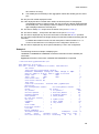
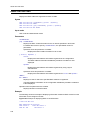
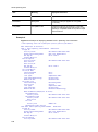
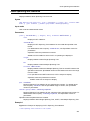
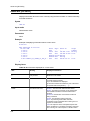
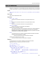
Command description format
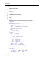
Each command is described in the following format:
Function
Describes the purpose of the command.
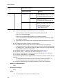
Syntax
Defines the input format of the command. The format is governed by the following rules:
1.
Parameters for setting values or character strings are enclosed in angle brackets
(<>).
2.
Characters that are not enclosed in angle brackets (<>) are keywords that must be
typed exactly as they appear.
3.
{A|B} indicates that either A or B must be selected.
4.
Parameters or keywords enclosed in square brackets ([]) are optional and can be
omitted.
5.
For details about the parameter input format, see Specifiable values for parameters.
Input mode
Indicates the input mode (administrator mode, user mode, or administrator mode) that can
be used for the command.
Parameters
Describes in detail the parameters that can be set by the command. For details on the
behavior of a command when all omissible parameters are omitted, see Operation when all
parameters are omitted.
For details on the behavior when only a specific parameter is omitted, see Operation when
this parameter is omitted. For details on the behavior when each parameter is omitted, see
Operation when each parameter is omitted.
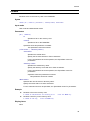
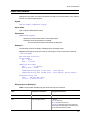
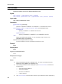
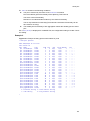
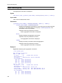
Example
Provides examples of appropriate command usage.
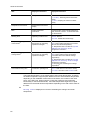
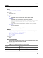
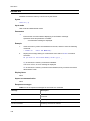
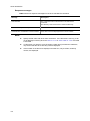
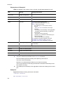
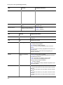
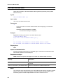
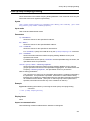
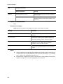
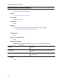
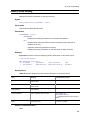
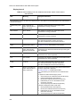
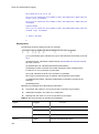
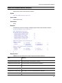
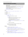
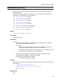
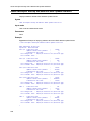
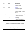
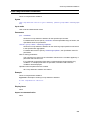
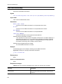
Display items
Describes the display items generated by the example.
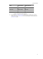
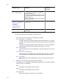
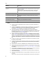
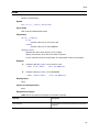
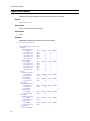
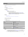
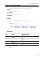
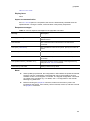
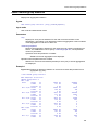
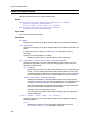
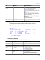
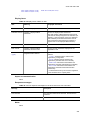
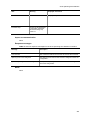
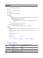
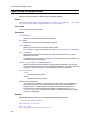
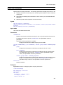
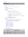
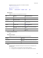
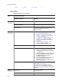
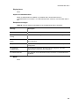
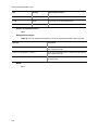
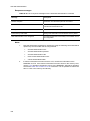
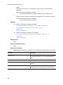
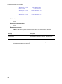
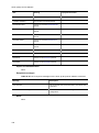
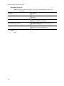
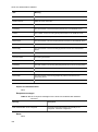
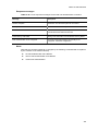
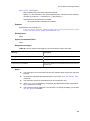
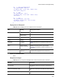
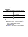
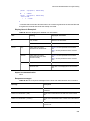
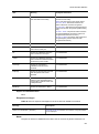
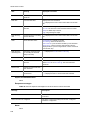
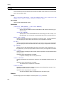
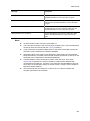
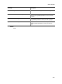
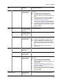
The following table describes the Date display item displayed immediately after the
command in the example is executed.
Table 1-1 Display of the time the command was received
Item
Displayed information
Date
yyyy/mm/dd hh:mm:ss timezone year/month/day hour:minute:second time
zone
Impact on communication
If a setting has an impact on communication, such as interruptions to communication, that
impact is described here.
2
1 Reading the Manual
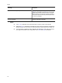
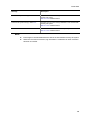
Response messages
Lists the response messages that can be displayed after execution of the command.
Note that the error messages displayed by entry-error detection function are not described
here. For these messages, see 36. Error Messages Displayed When Editing the
Configuration in the manual Configuration Command Reference.
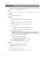
Notes
Provides cautionary information on using the command.
3
1 Reading the Manual
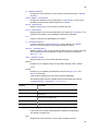
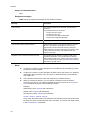
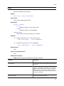
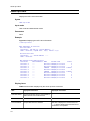
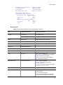
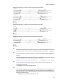
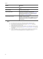
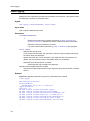
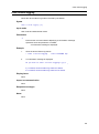
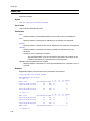
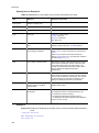
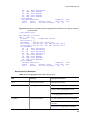
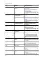
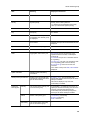
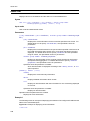
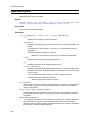
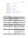
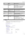
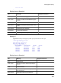
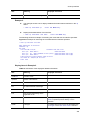
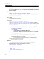
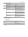
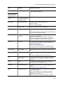
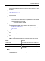
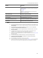
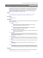
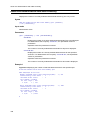
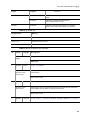
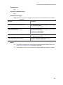
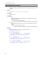
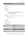
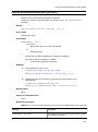
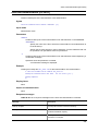
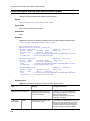
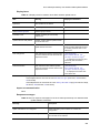
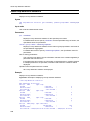
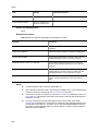
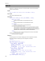
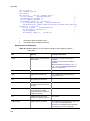
Specifiable values for parameters
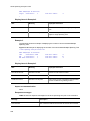
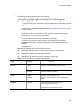
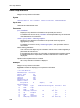
The following table describes the values that can be specified for parameters.
Table 1-2 Specifiable values for parameters
Parameter type
Description
Input example
Any character string
See List of character codes.
hostname K0_LITE_1
Access list name
QoS flow list name
See List of character codes.
Alphabetic characters can be used for the first
character, and alphanumeric characters,
hyphens (-), underscores (_), and periods (.)
can be used for the other characters.
Any other characters can be entered, but
specify the above type characters.
Do not specify the character string,
resequence, or the character strings beginning
with resequence.
mac access-list extended
list101
QoS queue list name
DHCP address pool
name
See List of character codes.
Alphabetic characters can be used for the first
character, and alphanumeric characters,
hyphens (-), underscores (_), and periods (.)
can be used for the other characters.
Any other characters can be entered, but
specify the above type characters.
ip dhcp pool floorA
File name#1
You can use alphanumeric characters,
hyphens (-), underscores (_), and periods (.).
See also The file names used on the
RAMDISK or on the memory card.
backup mc backup.cnf
File name
Specify a file name or a file name with the path
name#2.
You can use a forward slash (/) as the path
delimiter.
backup mc
my_dir/backup.cnf
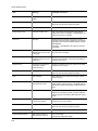
Directory name#3
Specify a directory name or a directory name
with the path name#2.
You can use a forward slash (/) as the path
delimiter.
mkdir my_dir
Base name
Specify only the file name.
You cannot use a forward slash (/).
rename mc
my_dir/backup.cnf bup.cnf
MAC address,
MAC address mask
Specify these items in hexadecimal format,
separating 2-byte hexadecimal values by
periods (.).
1234.5607.08ef
0000.00ff.ffff
IPv4 address,
IPv4 subnet mask
Specify these items in decimal format,
separating 1-byte decimal values by periods
(.).
192.168.0.14
255.255.255.0
IPv6 address
Specify this item in hexadecimal format,
separating 2-byte hexadecimal values by
colons (:).
3ffe:501:811:ff03:87ff:f
ed0:c7e0
#1: When you specify a file name (for example, when using the copy command), add the
4
1 Reading the Manual
file extension.
(Example: xx.dat, xx.txt)
If you do not use a file extension when specifying a file name, a command execution
error might occur.
#2: A forward slash is used as the path delimiter. A path name beginning with a forward
slash is not allowed.
Also, a path name meeting any of the following conditions is not allowed:
The path name contains two successive periods (..).
The path name contains a period (.). The only exception is a path name that
consists only of one period.
The path name contains successive forward slashes.
(Example: foo//baa)
The path name ends with a forward slash.
(Example: foo/)
#3: If the total number of characters in a directory name and its subordinate file name
exceeds 64 characters, the character string will not be displayed correctly by some
commands (for example, show mc-file or show ramdisk-file).
Therefore, specify a directory name in which the total number of characters, including the
subordinate file name, does not exceed the maximum allowed number of characters. Keep
this in mind especially when using the mkdir command to create a directory.
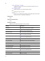
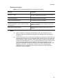
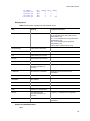
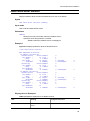
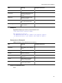
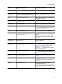
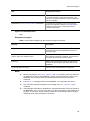
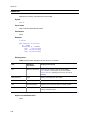
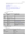
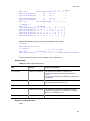
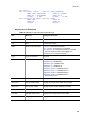
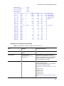
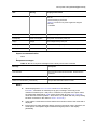
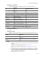
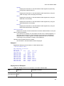
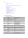
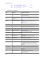
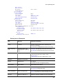
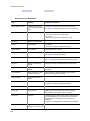
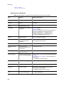
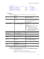
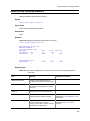
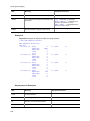
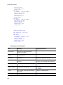
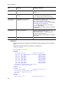
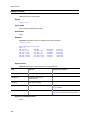
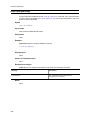
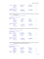
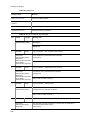
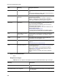
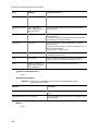
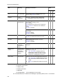
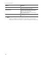
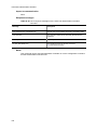
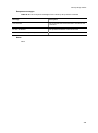
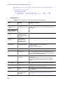
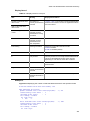
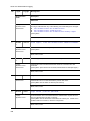
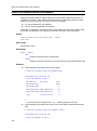
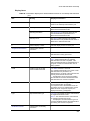
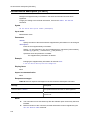
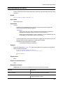
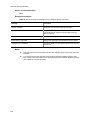
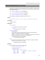
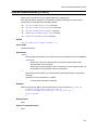
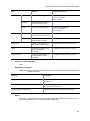
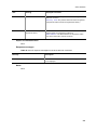
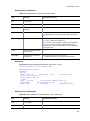
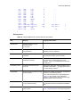
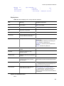
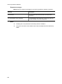
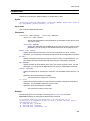
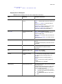
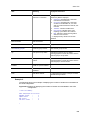
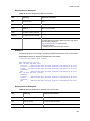
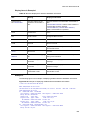
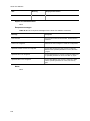
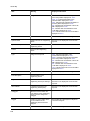
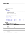
<IF#> Parameter range
Specify the <IF#> parameter in the format NIF-No./Port-No. (include the last period).
NIF-No. of the Switch is fixed at zero.
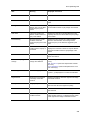
The following tables list the range of <IF#> values.
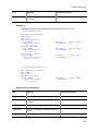
Table 1-3 Range of <IF#> values for AX2200S series switches
#
Model
Interface type
Range of values
1
AX2230S-24T
gigabitethernet
0/1 to 0/28
2
AX2230S-24P
gigabitethernet
0/1 to 0/28
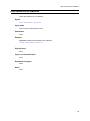
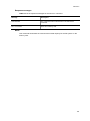
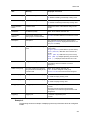
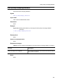
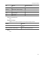
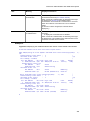
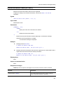
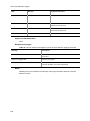
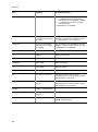
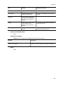
Table 1-4 Range of <IF#> values for AX1250S series switches
#
Model
Interface type
Range of values
1
AX1250S-24T2C
fastethernet
0/1 to 0/24
gigabitethernet
0/25 to 0/26
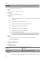
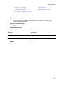
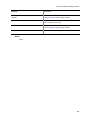
Table 1-5 Range of <IF#> values for AX1240S series switches
#
Model
Interface type
Range of values
1
AX1240S-24T2C/AX1240S-24P2C
fastethernet
0/1 to 0/24
gigabitethernet
0/25 to 0/26
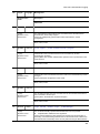
5
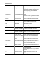
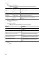
1 Reading the Manual
#
Model
Interface type
Range of values
2
AX1240S-48T2C
fastethernet
0/1 to 0/48
gigabitethernet
0/49 to 0/50
How to specify <IF# list> <Port# list> and the range of the specifiable values
If <IF# list> <Port# list> is written in parameter input format, use a hyphen (-) or commas
(,) in the <IF#> format to specify multiple ports. You can also specify one port, as when
<IF#> is written as the parameter input format. The range of specifiable values is the same
as the range of <IF#> values in the above table.
Example of a range specification that uses a hyphen (-) and commas (,):
0/1-3,0/5
How to specify <VLAN ID list>
If <VLAN ID list> is written in parameter input format, use a hyphen (-) or commas (,) to
specify multiple VLAN IDs. You can also specify one VLAN ID, as when <VLAN ID> is
written as the parameter input format. The range of permitted values is VLAN ID=1 (VLAN
ID for the default VLAN) and other VLAN IDs set by the configuration command.
Example of a range specification that uses a hyphen (-) and commas (,):
1-3,5,10
How to specify <Channel group# list>
If <Channel group# list> is written in parameter input format, use a hyphen (-) or commas
(,) to specify multiple channel group numbers. You can also specify one channel group
number. The range of permitted values for the channel group number is all the channel
group numbers set by the configuration command.
Example of a range specification that uses "-" or ",":
1-3,5
The file names used on the RAMDISK or on the memory card
For details about the parameter range specifiable for each command, see the description
for each command or Specifiable values for parameters.
The following limitations exist for parameters outside the specifiable range for parameters:
The file names are not case sensitive.
A file name or a directory name ended with a period (.) cannot be used.
The file names used on the FTP servers
For details about the parameter range specifiable for each command, see the description
for each command or Specifiable values for parameters.
Some server-dependent limitations other than the specifiable range for parameters might
exist. For details, see the specifications of the server.
When using the Switch as an FTP server, the descriptions in The file names used on the
RAMDISK or on the memory card above are applied.
6
1 Reading the Manual
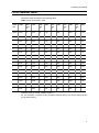
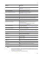
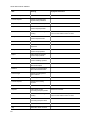
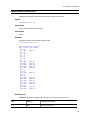
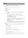
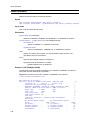
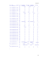
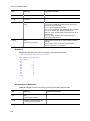
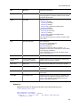
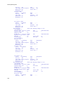
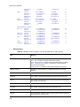
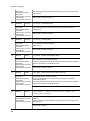
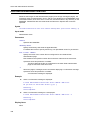
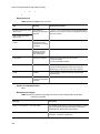
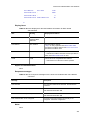
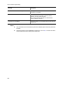
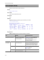
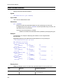
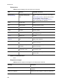
List of character codes
Character codes are listed in the following table.
Table 1-6 List of character codes
Chara
cter
Code
Cha
ract
er
Code
Cha
ract
er
Code
Cha
ract
er
Code
Cha
ract
er
Code
Cha
ract
er
Code
Space
0x20
0
0x30
@
0x40
P
0x50
`
0x60
p
0x70
!
0x21
1
0x31
A
0x41
Q
0x51
a
0x61
q
0x71
"
0x22
2
0x32
B
0x42
R
0x52
b
0x62
r
0x72
#
0x23
3
0x33
C
0x43
S
0x53
c
0x63
s
0x73
$
0x24
4
0x34
D
0x44
T
0x54
d
0x64
t
0x74
%
0x25
5
0x35
E
0x45
U
0x55
e
0x65
u
0x75
&
0x26
6
0x36
F
0x46
V
0x56
f
0x66
v
0x76
'
0x27
7
0x37
G
0x47
W
0x57
g
0x67
w
0x77
(
0x28
8
0x38
H
0x48
X
0x58
h
0x68
x
0x78
)
0x29
9
0x39
I
0x49
Y
0x59
i
0x69
y
0x79
*
0x2A
:
0x3A
J
0x4A
Z
0x5A
j
0x6A
z
0x7A
+
0x2B
;
0x3B
K
0x4B
[
0x5B
k
0x6B
{
0x7B
,
0x2C
<
0x3C
L
0x4C
\
0x5C
l
0x6C
|
0x7C
-
0x2D
=
0x3D
M
0x4D
]
0x5D
m
0x6D
}
0x7D
.
0x2E
>
0x3E
N
0x4E
^
0x5E
n
0x6E
~
0x7E
/
0x2F
?
0x3F
O
0x4F
_
0x5F
o
0x6F
---
---
#1
#2
#1
#1: To enter this character as part of a character string, you must enclose the entire
character string in double quotation marks (").
#2: This character is used to enclose an entire character string. You cannot enter it as part
of a character string.
7
1 Reading the Manual
Messages displayed by the entry-error detection functionality
For error messages output by the entry-error detection function (see 5.2.3 Entry-error
detection functionality in the Configuration Guide Vol. 1), see 36. Error Messages
Displayed When Editing the Configuration in the manual Configuration Command
Reference.
8
Part 2: Basic Operation
2. Switching the Command Input Mode
enable
disable
exit
logout
configure
9
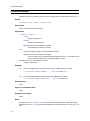
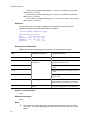
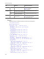
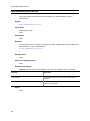
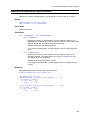
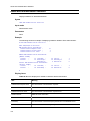
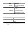
enable
enable
Changes the command input mode from user mode to administrator mode. In administrator
mode, you can execute commands, such as the configure command, which cannot be
input from user mode.
Syntax
enable
Input mode
User mode
Parameters
None
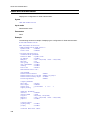
Example
Changes the command input mode from user mode to administrator mode.
> enable
Press the Enter key.
password: ******
#
If password authentication is successful, the administrator mode prompt (#) is displayed.
Display items
None
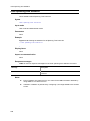
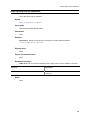
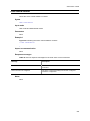
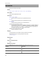
Impact on communication
None
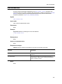
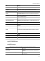
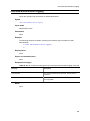
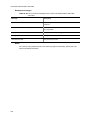
Response messages
Table 2-1 List of response messages for the enable command
Message
Description
Sorry.
The mode cannot be changed to administrator mode because
a password entry error occurred.
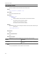
Notes
10
Initially, no password is set. To ensure better security, we recommend that you use
the password command to set the password.
Help for this command is also displayed in administrator mode. Although you enter
this command in administrator mode, the command input mode will not change.
disable
disable
Changes the command input mode from administrator mode to user mode.
Syntax
disable
Input mode
Administrator mode
Parameters
None
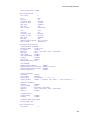
Example
Changes the command input mode from administrator mode to user mode.
#
>
disable
Press the Enter key.
Display items
None
Impact on communication
None
Response messages
None
Notes
None
11
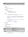
exit
exit
Ends the current command input mode as follows:
1.
If you are in user mode or administrator mode, you are logged out from the device.
2.
Ends configuration command mode and returns you to administrator mode.
Syntax
exit
Input mode
User mode and administrator mode
Parameters
None
Example
1.
Ends administrator mode and logs out from the device.
# exit
2.
Press the Enter key.
End the configuration command mode.
(config)# exit
Press the Enter key.
#
Display items
None
Impact on communication
None
Response messages
None
Notes
Use the disable command to return the command input mode from administrator mode to
user mode.
12
logout
logout
Logs out from the device.
Syntax
logout
Input mode
User mode and administrator mode
Parameters
None
Example
In administrator mode, log out from the command input mode.
# logout
login:
Press the Enter key.
Display items
None
Impact on communication
None
Response messages
None
Notes
None
13
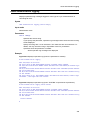
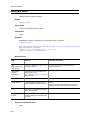
configure
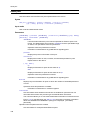
configure
Changes the command input mode from administrator mode to configuration command
mode when the command input mode is administrator mode, and initiates configuration
editing.
Syntax
configure [terminal]
Input mode
Administrator mode
Parameters
terminal
Enables editing of the running configuration during operation.
Example
Change the command input mode from administrator mode to configuration command
mode.
# configure
(config)#
Press the Enter key.
Display items
None
Impact on communication
None
Response messages
None
Notes
The device starts operation at power up based on the settings in the startup configuration
file. To change the settings, you can use this configuration command, which immediately
applies a settings change. If you do not save the settings configured by using the
configuration command to the startup configuration file, the configuration settings will be
lost when the device is restarted. Care is therefore necessary. We recommend that you
execute the save configuration command or the copy operation command to save the
settings to the startup configuration file.
14
3. Terminals and Remote Operations
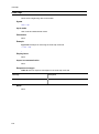
set exec-timeout
set terminal pager
telnet
ftp
line console speed
trace-monitor
15
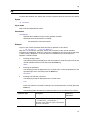
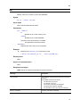
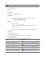
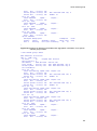
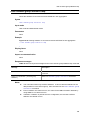
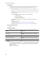
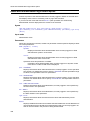
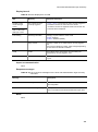
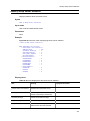
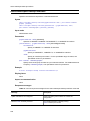
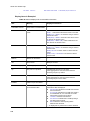
set exec-timeout
set exec-timeout
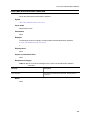
Sets the idle time (in minutes) for auto-logout (see 4.3 (3) Auto-logout in the Configuration
Guide Vol. 1).
Syntax
set exec-timeout <Minutes> [save]
Input mode
User mode and administrator mode
Parameters
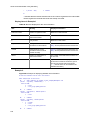
<Minutes>
Specifies the time for auto-logout in minutes.
Specifiable values
0-60 (If 0 is specified, auto logout is not performed.)
save
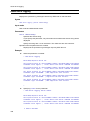
Saves the setting of the auto-logout time to the internal flash memory.
Operation when this parameter is omitted:
The new setting is not saved to the internal flash memory. If you either log out
from or restart the device, the old auto-logout time setting is used.
Operation when this command is not used:
The auto-logout time is set to 30 minutes.
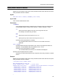
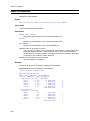
Example
Set the auto-logout value to 10 minutes, and then save the setting.
> set exec-timeout 10 save
Press the Enter key.
Display items
None
Impact on communication
None
Response messages
None
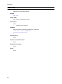
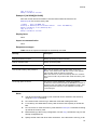
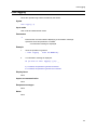
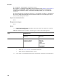
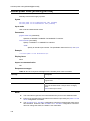
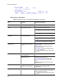
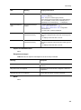
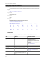
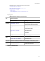
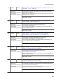
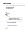
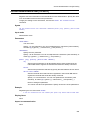
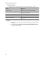
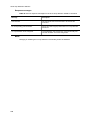
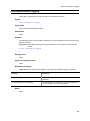
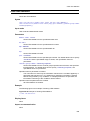
Notes
16
When the set terminal pager command has been executed with the enable
parameter specified, if "Press any key to continue (Q to quit)" is displayed and
the display halts temporarily, you will be returned to the prompt after the set time
elapses and thereafter be logged out from the device.
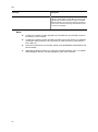
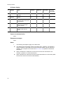
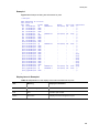
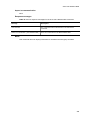
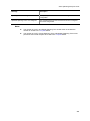
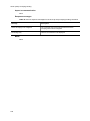
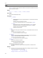
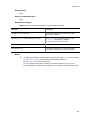
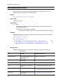
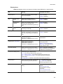
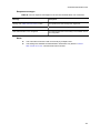
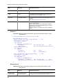
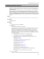
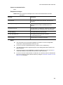
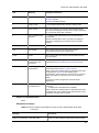
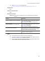
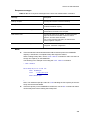
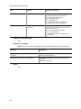
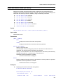
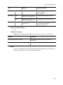
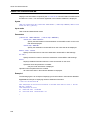
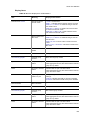
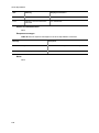
The following shows the objects that are the target of the auto-logout functionality.
set exec-timeout
Target
set exec-timeout
Default logout time
Console
Y (0-60 minutes)
30 minutes
Telnet server
Y (0-60 minutes)
30 minutes
FTP server
N
30 minutes
Legend Y: Supported; N: Not supported
Executing the show running-config command does not display this command
setting. Executing the show system command will display the saved setting in the
System Setting item.
17
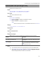
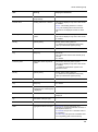
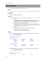
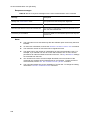
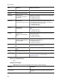
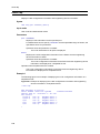
set terminal pager
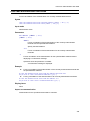
set terminal pager
Specifies whether to perform paging (see 5.2.6 Paging in the Configuration Guide Vol. 1).
Syntax
set terminal pager {enable | disable} [save]
Input mode
User mode and administrator mode
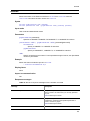
Parameters
{ enable | disable }
enable
Paging is performed.
disable
Paging is not performed.
Operation when this parameter is omitted:
This parameter cannot be omitted.
save
Saves the paging setting to the internal flash memory.
Operation when this parameter is omitted:
The new setting is not saved to the internal flash memory. If you either log out
from or restart the device, the old paging setting is used.
Operation when this command is not used:
Paging is performed.
Example
Set so that paging will not be performed and the setting will not be saved.
> set terminal pager disable
Press the Enter key.
Set so that paging will be performed and the setting will be saved.
> set terminal pager enable save
Press the Enter key.
Display items
None
Impact on communication
None
Response messages
None
Notes
Executing the show running-config command does not display this command setting.
Executing the show system command will display the saved setting in the System Setting
item.
18
telnet
telnet
Connects via Telnet, as a Telnet client, to the remote host that has the specified IP address.
Syntax
telnet <IP address>
Input mode
User mode and administrator mode
Parameters
<IP address>
Specifies an IP address.
Operation when this parameter is omitted:
This parameter cannot be omitted.
Example
1.
Access the remote host whose IP address is 192.168.0.1 via Telnet.
> telnet 192.168.0.1
Press the Enter key.
After the telnet command is executed, the following message indicating that you
will need to wait for the connection with the remote host to be established is
displayed.
Trying 192.168.0.1 ...
2.
After the connection is established with the remote host, you can enter the login
name and password.
login: username
Password: ********
Press the Enter key.
Press the Enter key.
Display items
None
Impact on communication
None
Response messages
Table 3-1 List of response messages for the telnet command
Message
Description
Trying <host>...
Trying to connect to <host>.
<host>: Remote host
Notes
To interrupt the processing while Trying... is displayed, press the Ctrl+Shift+6
keys and then the X key.
19
telnet
20
To break the attempted connection, press the Ctrl+Shift+6 keys and then the B key.
Other escape sequences are not supported.
This command sends the input key codes to the login destination host without
making any modifications. Therefore, the key code used on the terminal on which
this command is entered must be the same as the key code recognized by the
destination host. If they are different, the command will not operate correctly. For
example, as the input key code for the Enter key, some terminals generate only CR,
whereas other terminals generate CR and LF. Also, when a destination device
recognizes the Enter key, some devices only recognize CR, whereas other devices
recognize CR and LF. Check the settings of the input terminal and the login
destination device beforehand.
ftp
ftp
Transfers files between the Switch and a remote operation terminal connected via TCP/IP.
Syntax
ftp <IP address>
Input mode
User mode and administrator mode
Parameters
<IP address>
Specifies the IP address of the remote operation terminal.
Operation when this parameter is omitted:
This parameter cannot be omitted.
Example
Logs in to the remote operation terminal whose IP address is 192.168.0.1.
> ftp 192.168.0.1
Press the Enter key.
After the ftp command is executed, wait for the connection to the remote operation
terminal to be established. When the connection is established, the input prompt (see steps
1 and 2 below) is displayed. If a connection is not established, the mode returns to
operation command mode.
1.
Entering the login name:
The following prompt is displayed on the command line. Enter the login name for the
remote operation terminal, and then press the Enter key.
Name:
2.
Entering the password:
The following prompt is displayed on the command line. Enter the password for the
specified login name, and then press the Enter key.
Password:
3.
Entering a file transfer command:
The following prompt is displayed on the command line.
ftp>
Enter a file transfer command according to the transfer direction, and then press the
Enter key.
The following table describes the parameters that can be specified for file transfer.
Parameter type
Description
Number of
characters
<Local file>
You can use alphanumeric characters, hyphens
(-), underscores (_), and periods (.).
See Base name under File name in Specifiable
values for parameters.
1 to 64 characters
21
ftp
Parameter type
Description
Number of
characters
<Local files>
mget <Remote files>
You can use alphanumeric characters, hyphens
(-), underscores (_), periods (.), asterisks (*),
and question marks (?).
If the character string includes a question mark
(?), enclose the entire character string in double
quotation marks (").
See Base name under File name in Specifiable
values for parameters.
1 to 64 characters
<Remote file>
mdelete <Remote files>
<From name>
<To name>
<Remote directory>
<Directory name>
See Any character string in Specifiable values
for parameters.
1 to 1024 characters
<Mode>
See Any character string in Specifiable values
for parameters.
1 to 64 characters
#: File names that end with a period (.) cannot be used.
The input format of the file transfer commands is as follows:
get <Remote file> [<Local file>]
Transfers a file from the remote operation terminal to the Switch. If <Local file>
is omitted, the file name becomes the name of the file on the remote operation
terminal.
If <Remote file> does not meet the input conditions for <Local file> (number of
characters and character type), make sure you specify <Local file>.
mget <Remote files>
Use this command to receive multiple files. Enter the command in the format
mget *.txt.
put <Local file> [<Remote file>]
Transfers a file from the Switch to the remote operation terminal. If <Remote
file> is omitted, the file name becomes the name of the file on the Switch.
mput <Local files>
Use this command to send multiple files. Enter the command in the format
mput *.txt.
4.
Entering a command other than a file transfer command:
If the prompt ftp> is displayed, the following commands can be executed in addition
to the get and put commands:
ascii
Sets ASCII as the transfer format of the file.
binary
Sets binary as the transfer format of the file.
[ bye | quit | exit ]
Ends the FTP session, and then the ftp command.
22
ftp
cd <Remote directory>
Changes the current directory on the remote operation terminal to <Remote
directory>.
chmod <Mode> <Remote file>
Changes the attribute of the file specified for <Remote file> on the remote
operation terminal to the attribute specified for <Mode>.
delete <Remote file>
Deletes <Remote file> on the remote operation terminal.
help [<Command>]
Displays Help for the command specified by the argument <command>. If no
argument is specified, a list of available commands is displayed.
lols
Lists the contents of the RAMDISK on the Switch.
ls [<Remote directory>]
Lists the contents of <Remote directory> (current directory if <Remote
directory> is not specified) on the remote operation terminal.
mdelete [<Remote files>]
Deletes <Remote files> on the remote operation terminal. Use this command
when multiple files must be deleted. Enter the command in the format
mdelete *.txt.
mkdir <Directory name>
Creates a directory on the remote operation terminal.
passive
Enables (on) or disables (off) the use of passive transfer mode. Default
is off.
prompt
Enables (on) or disables (off) interactive mode for the mget, mput, and
mdelete commands.
If this mode is enabled (on), files can be selected separately.
The following table shows the display format and describes the options.
<Command name> <File name> [y/n/a/q/?]?
Display
Description
y
Executes the file.
n
Skips the file.
a
Executes all subsequent files.
q
Ends command execution.
?
Displays Help.
If the mode is off, all files are transferred or deleted unconditionally.
The default is enabled (on).
pwd
Displays the current directory on the remote operation terminal.
23
ftp
rename <From name> <To name>
Changes the name of a file on the remote operation terminal from <From
name> to <To name>.
rmdir <Directory name>
Deletes a directory on the remote operation terminal.
status
Displays the current FTP status.
verbose
Enables (on) or disables (off) the display of the detailed response information
from the FTP server. The default is enabled (on).
Display items
None
Impact on communication
None
Response messages
Table 3-2 List of response messages for the ftp command
Message
Description
Connecting...
Connection to the FTP server is in progress.
Error: Ambiguous command.
The command can be interpreted in two or more ways and
therefore cannot be identified uniquely.
Error: Bad command.
The command was not entered correctly.
Error: Can't get file names.
A file list could not be acquired when the mget, mput, or
mdelete command was executed.
Error: Can't open "<File name>".
A file could not be opened.
<File name>:The specified file name
Error: Command send failed.
A communication error occurred.
Error: Connect failed.
An attempt to connect to the FTP server failed.
Error: Data accept failed.
A communication error occurred.
Error: Data connect failed.
A communication error occurred.
Error: Data receive failed.
A communication error occurred.
Error: Data send failed.
A communication error occurred.
Error: File not found "<File name>".
The specified file could not be found.
<File name>:The specified file name
Error: File read failed.
A file could not be read.
Error: File write failed.
Writing to a file failed.
24
ftp
Message
Description
Error: Invalid file name "<File name>".
The file name is invalid (for example, an invalid character string
was used).
<File name>:The specified file name
Error: Invalid parameter.
An entered parameter was invalid.
Error: Is a directory "<File name>".
The specified <File name> is a directory.
<File name>:The specified file name
Error: Missing parameter.
A parameter is missing.
Error: Reply receive failed.
A communication error occurred.
Error: String must be more than 0 characters.
The character string must have one or more characters.
Error: String too long.
The character string is too long.
Error: The command execution failed,
because "xxx" is executing.
The command is being executed by another user. Wait a while
and then try again, or else check whether another user is
running the command.
xxx:Information regarding another user (for example,
console, vty0, vty1 is displayed.)
Error: Too long file name.
The file name is too long.
(In the file name list of the mput, mget, or mdelete command)
Error: Too many parameters.
There are too many parameters.
Error: Too much file entries.
There are too many files.
(In the file name list of the mput, mget, or mdelete command)
Passive: off
Passive mode has been disabled.
Passive: on
Passive mode has been enabled.
Prompting: off
Interactive mode for the mput, mget, or mdelete command
has been disabled.
Prompting: on
Interactive mode for the mput, mget, or mdelete command
has been enabled.
Type: ascii
The type for sending and receiving files has been set to ASCII.
Type: binary
The type for sending and receiving files has been set to binary.
Verbose: off
Display of a detailed response has been disabled.
Verbose: on
Display of a detailed response has been enabled.
Notes
1.
A user ID whose password is not set on the destination terminal might not be able to
log in via FTP. If this occurs, set the password on the destination terminal, and then
execute the ftp command again.
2.
If commands cannot be input, enter Ctrl+C and exit.
25
ftp
26
3.
A local directory on the Switch can be moved only to /ramdisk.
4.
A local file on the Switch can be sent to or received from /ramdisk only.
5.
If the default file transfer format is ASCII, you will need to execute the binary
command to enable the transfer of binary files.
6.
If you press Ctrl+C while a file is being transferred with a get or put command, the
file transfer is immediately interrupted. The interruption is reported to the remote
operation terminal and a response is waited for. Therefore, if some communication
failures occur between the Switch and the remote operation terminal, you might not
see any ftp prompts even if you press Ctrl+C. In this case, press Ctrl+C again.
line console speed
line console speed
Specifies the communication speed of CONSOLE (RS-232C). If a user has already logged
in from CONSOLE (RS-232C) when the communication speed is changed, the speed
changes immediately. If the communication speed is changed from a remote operation
terminal while login authentication for a user who is trying to log in from CONSOLE
(RS-232C) is in progress, the authentication might fail.
Syntax
line console speed <Transmission rate> [save]
Input mode
User mode and administrator mode
Parameters
<Transmission rate>
Specifies the communication speed of CONSOLE (RS-232C).
Specifiable communication speeds:
1200, 2400, 4800, 9600, 19200
Operation when this parameter is omitted:
This parameter cannot be omitted.
save
Saves the new communication speed setting to the internal flash memory.
Operation when this parameter is omitted:
The new communication speed setting is not saved to the internal flash
memory. If you restart the device, the old communication speed setting is
used.
Operation when this command is not used:
CONSOLE (RS-232C) operates at 9600 bps.
Example
Change and save the communication speed.
> line console speed 19200 save
Press the Enter key.
Do you wish to continue? (y/n): y
Display items
None
Impact on communication
None
Response messages
None
Notes
Using this command to change the communication speed immediately changes the
speed. If the communication speed is changed from a remote operation terminal
27
line console speed
while login authentication for a user who is trying to log in from CONSOLE
(RS-232C) is in progress, the authentication might fail.
28
For login to the Switch from CONSOLE (RS-232C) and via Telnet, if the Telnet side
changes the communication speed with this command and then logs out, the
CONSOLE (RS-232C) communication speed also changes, disabling
communication from CONSOLE (RS-232C).
Executing the show running-config command does not display this command
setting. Executing the show system command will display the saved setting in the
System Setting item.
trace-monitor
trace-monitor
Specifies whether to display the operation log on the monitor. When this command is
entered with the enable parameter specified, the operation log is displayed on the console
whenever necessary each time an event occurs.
Syntax
trace-monitor {enable | disable} [save]
Input mode
User mode and administrator mode
Parameters
{ enable | disable }
enable
The operation log is displayed on the monitor.
disable
The operation log is not displayed on the monitor.
Operation when this parameter is omitted:
This parameter cannot be omitted.
save
The new setting is saved to the internal flash memory.
Operation when this parameter is omitted:
The new setting is not saved to the internal flash memory. If you restart the
device, the old monitor display setting is used.
Operation when this command is not used:
The operation log is displayed on the monitor.
Example
Do not display the operation log on the monitor, or save the setting.
> trace-monitor disable
Press the Enter key.
Display the operation log on the monitor, and save the setting.
> trace-monitor enable save
Press the Enter key.
Display items
None
Impact on communication
None
Response messages
None
Notes
Executing the show running-config command does not display this command
setting. Executing the show system command will display the saved setting in the
29
trace-monitor
System Setting item.
30
After execution of the trace-monitor enable command, if an operation log is too
large to be displayed on the monitor, the message WARNING !! There are too many
messages to output. appears.
4. Configurations and File Operations
show running-config
show startup-config
copy
erase startup-config
rename
del
mkdir
rmdir
31
show running-config
show running-config
Displays the running configuration.
Syntax
show running-config
Input mode
Administrator mode
Parameters
None
Example
None
Display items
None
Impact on communication
None
Response messages
Table 4-1 List of response messages for the show running-config command
Message
Description
Can't execute.
The command could not be executed. Re-execute the command.
CAUTION!!! This configuration list is
too big!!! (xxxxxxx byte)
x:Indicates the size of running-config.
The running-config list is too large.
The running-config list exceeds 1 MB, so it cannot be saved to
startup-config.
Review the configuration.
Notes
If there are many items in the running configuration, command execution might take some
time.
32
show startup-config
show startup-config
Displays the startup configuration file used at device startup.
Syntax
show startup-config
Input mode
Administrator mode
Parameters
None
Example
None
Display items
None
Impact on communication
None
Response messages
None
Notes
None
33
copy
copy
Copies the specified file or directory.
Syntax
copy
copy
copy
copy
copy
copy
copy
copy
copy
copy
startup-config ramdisk {<File name> | <Directory name>}
running-config startup-config
running-config mc {<File name> | <Directory name>}
mc {<File name> | <Directory name>} mc {<File name> | <Directory name>}
mc {<File name> | <Directory name>} ramdisk {<File name> | <Directory name>}
ramdisk <File name> startup-config
ramdisk {<File name> | <Directory name>} ramdisk {<File name> | <Directory name>}
ramdisk {<File name> | <Directory name>} mc {<File name> | <Directory name>}
auto-log mc {<File name> | <Directory name>}
auto-log ramdisk {<File name> | <Directory name>}
Input mode
User mode and administrator mode for the following commands
copy
copy
copy
copy
mc {<File name> | <Directory name>} mc {<File name> | <Directory name>}
mc {<File name> | <Directory name>} ramdisk {<File name> | <Directory name>}
ramdisk {<File name> | <Directory name>} mc {<File name> | <Directory name>}
ramdisk {<File name> | <Directory name>} ramdisk {<File name> | <Directory name>}
For all other commands, only administrator mode is available.
Parameters
startup-config: Startup configuration file
running-config: Running configuration
auto-log:The device status information collected automatically after the device starts
{<File name> | <Directory name>}
<File name>
Specifies the name of a file at the copy source or copy destination.
Specify the file name with 64 or fewer characters. The file name is not case
sensitive.
For the characters that can be specified, see Specifiable values for
parameters.
<Directory Name>
Specifies the directory name at the copy source or copy destination.
Specify the directory name so that the total number of characters used in the
directory name and its subordinate file name is no more than 64. The file
name is not case sensitive.
For the characters that can be specified, see Specifiable values for
parameters.
startup-config ramdisk {<File name> | <Directory name>}
Copies the startup configuration file to the RAMDISK.
running-config startup-config
Copy the running configuration to the startup configuration file.
running-config mc {<File name> | <Directory name>}
Copies the running configuration to the memory card.
mc {<File name> | <Directory name>} mc {<File name> | <Directory name>}
Copies a file or directory on the memory card to the memory card.
34
copy
mc {<File name> | <Directory name>} ramdisk {<File name> | <Directory name>}
Copies a file or directory on the memory card to the RAMDISK.
ramdisk <File name> startup-config
Copies a file on the RAMDISK to the startup configuration file.
A directory on the RAMDISK cannot be specified.
ramdisk {<File name> | <Directory name>} mc {<File name> | <Directory name>}
Copies a file or directory on the RAMDISK to the memory card.
ramdisk {<File name> | <Directory name>} ramdisk {<File name> | <Directory name>}
Copies a file or directory on the RAMDISK to the RAMDISK.
auto-log mc {<File name> | <Directory name>}
Copies the auto-log information to the memory card.
auto-log ramdisk {<File name> | <Directory name>}
Copies the auto-log information to the RAMDISK
Example
Copy the running configuration to the startup configuration file. (If the copy
destination is the startup configuration file, a confirmation message is displayed.)
# copy running-config startup-config
Do you wish to copy from running-config to startup-config? (y/n): y
Copy a file on the RAMDISK to the startup configuration file. (If the copy destination
is the startup configuration file, a confirmation message is displayed.)
# copy ramdisk config1.txt startup-config
Do you wish to copy from RAMDISK to startup-config? (y/n): y
Display items
None
Impact on communication
If a file on the RAMDISK is copied to the startup configuration file, you must restart the
device to apply the file to the running configuration. Restart the device by executing the
reload operation command, or by turning it off and then on again.
Response messages
Table 4-2 List of response messages for the copy command
Message
Description
Can't execute.
The command could not be executed. Re-execute the command.
The possible causes are as follows:
- The file name is incorrect.
- The file was not found.
- The memory card might be damaged.
- The file system might be damaged.
35
copy
Message
Description
Can't access to MC by write
protection.
Make sure the memory card's protect switch is not set to Lock. If the
switch is set to Lock, move it to the opposite side, and then insert the
memory card again.
Make sure there is no dust in the memory card slot. If there is dust,
remove it with a dry cloth and then insert the memory card again.
Can't copy subdirectory.
Subdirectories cannot be copied.
File name length exceeds the limit.
The file name or the directory, including its path name, exceeds 64
characters.
MC is not inserted.
A memory card was not inserted.
Not enough space on device.
Capacity at the write destination is insufficient.
Source and destination are identical.
The source and destination files for a transfer exist at the same location.
Notes
Editing the startup configuration file has no effect on the running configuration or
communication.
If a file on the RAMDISK is copied to the startup configuration file, you must restart
the device to apply the file to the running configuration. Restart the device by
executing the reload command, or by turning it off and then on again.
If the copy destination is the startup configuration file, the copy processing is
performed even if there is an error in the specified configuration file. After the device
is restarted, execute the show logging command to make sure the operation log
does not indicate an inconsistent configuration.
If there is insufficient free space for storing files, a configuration cannot be copied.
Use the show mc command and the show ramdisk command to check the unused
capacity. The necessary space required for copying a configuration is the total size
of the new configuration in the copy source and the existing configuration in the copy
destination. About 1MB of free capacity is required for a maximum-size configuration
file.
If a file on the memory card is specified, the command can be executed only when
the memory card is inserted.
If a file on the memory card is specified, the ACC LED on the device is on while the
command is being executed. Do not remove or insert the memory card while the
ACC LED is on.
Note that the file copied to the RAMDISK will be deleted when the device restarts.
Specify the file name with 64 or fewer characters. If the file name is too long, it will
not be displayed correctly when the show mc-file or show ramdisk-file command
is executed.
If you create the configuration file on your PC and save it to the memory card used
for operation, specify the file name with 64 or fewer characters.
You cannot view the auto-log file because it is a binary file that the manufacturer
uses for failure analysis.
If the source and destination files for a copy operation are the same, an error occurs
as follows:
When both the copy source and the copy destination are the memory card and the
36
copy
file names (including their path names) are the same
When both the copy source and the copy destination are the RAMDISK and the file
names (including their path names) are the same
Example: When the mc <File name> mc <File name> command is executed:
copy mc aaa mc aaa Not allowed
copy mc bbb/xxx mc bbb/xxx Not allowed
copy mc bbb/xxx mc bbb/yyy OK
If there are any subdirectories in the copy source directory, an error occurs.
If the name of a directory at the copy destination is the same as the name of the
source directory, the source file is copied to that directory or overwrites a file in that
directory.
37
erase startup-config
erase startup-config
Deletes the contents of the startup configuration file.
Syntax
erase startup-config
Input mode
Administrator mode
Parameters
None
Example
#erase startup-config
Do you wish to erase startup-config? (y/n): y
#
Display items
None
Impact on communication
None
Response messages
None
Notes
If you restart the device after executing this command, the contents of the startup
configuration file will be deleted. In such cases, you will not be able to log in via the
network.
38
rename
rename
Renames a file on the memory card or the RAMDISK.
Syntax
rename {mc | ramdisk} {<File name> | <Directory name>} <Base name>
Input mode
User mode and administrator mode
Parameters
{mc | ramdisk}
mc
Specifies a file on the memory card.
ramdisk
Specifies a file on the RAMDISK.
Operation when this parameter is omitted:
This parameter cannot be omitted.
{<File name> | <Directory name>}
<File name>
Specifies the old file name.
Specify the file name with 64 or fewer characters.
For the characters that can be specified, see Specifiable values for
parameters.
<Directory name>
Specifies the old directory name.
Specify the directory name with 64 or fewer characters.
For the characters that can be specified, see Specifiable values for
parameters.
Operation when this parameter is omitted:
This parameter cannot be omitted.
<Base name>
Specifies the new file name or directory name.
Specify the name with 64 or fewer characters.
For the characters that can be specified, see Specifiable values for parameters.
Example
Rename a file on the memory card.
# rename mc abc/showtech.txt shotech_01.txt
Press the Enter key.
Rename a directory on the memory card.
# rename mc abc efg
Press the Enter key.
Display items
None
39
rename
Impact on communication
None
Response messages
Table 4-3 List of response messages for the rename command
Message
Description
Can't execute.
The command could not be executed. Re-execute the
command.
The possible causes are as follows:
- The file name is incorrect.
- The file was not found.
- The memory card might be damaged.
- The file system might be damaged.
MC is not inserted.
A memory card was not inserted.
Can't access to MC by write protection.
Make sure the memory card's protect switch is not set to
Lock. If the switch is set to Lock, move it to the
opposite side, and then insert the memory card again.
Make sure there is no dust in the memory card slot. If there
is dust, remove it with a dry cloth and then insert the
memory card again.
Resultant name exceeds the maximum length.
The new file name or directory, including its path name,
exceeds 64 characters. If the old file name or directory
name includes a path name, specify <Base name> with no
more characters than the value of 64 minus the number of
characters in the path name.
Notes
If a file on the memory card is specified, the command can be executed only when
the memory card is inserted.
If a file on the memory card is specified, the ACC LED on the device is on while the
command is being executed. Do not remove or insert the memory card while the
ACC LED is on.
This command cannot move a file from a directory to another directory.
When you rename a directory, you can specify a maximum of 64 characters.
However, if you do so, you might not be able to use a long name in the show and
copy commands as shown by the following example:
Example:
Old directory name: short-dir (20 characters)
Old file name: long-file (40 characters)
New directory name: long-dir (30 characters)
rename ramdisk short-dir long-dir
In this case, the total number of characters for the directory name and the file name
becomes 70, which exceeds the limit of 64. Therefore, you cannot use these names
in the show and copy commands.
40
del
del
Deletes a file on the memory card or the RAMDISK.
Syntax
del {mc | ramdisk} <File name>
Input mode
User mode and administrator mode
Parameters
{mc | ramdisk}
mc
Specifies a file on the memory card.
ramdisk
Specifies a file on the RAMDISK.
Operation when this parameter is omitted:
This parameter cannot be omitted.
<File name>
Specifies the name of the file to be deleted.
Example
Delete the file showtech_01 on the memory card.
> del mc abc/showtech_01.txt
Press the Enter key.
Display items
None
Impact on communication
None
Response messages
Table 4-4 List of response messages for the del command
Message
Description
Can't execute.
The command could not be executed. Re-execute the
command.
The possible causes are as follows:
- The file name is incorrect.
- The file was not found.
- The memory card might be damaged.
- The file system might be damaged.
- The specified name is the name of a directory.
MC is not inserted.
A memory card was not inserted.
41
del
Message
Description
Can't access to MC by write protection.
Make sure the memory card's protect switch is not set
to Lock. If the switch is set to Lock, move it to the
opposite side, and then insert the memory card again.
Make sure there is no dust in the memory card slot. If
there is dust, remove it with a dry cloth and then insert
the memory card again.
Notes
42
If a file on the memory card is specified, the command can be executed only when
the memory card is inserted.
If a file on the memory card is specified, the ACC LED on the device is on while the
command is being executed. Do not remove or insert the memory card while the
ACC LED is on.
Even if this command is not executed, all files on the RAMDISK are deleted when the
device restarts.
Attempting to delete a directory by using this command results in error. For details
about deleting a directory, see the description of the rmdir command.
mkdir
mkdir
Creates a new directory.
Syntax
mkdir {mc-dir | ramdisk} <Directory name>
Input mode
User mode and administrator mode
Parameters
{mc-dir | ramdisk}
mc-dir
Creates a directory on a memory card.
ramdisk
Creates a directory on the RAMDISK.
<Directory name>
Specifies the name of the directory to be created.
Specify the directory name with 64 or fewer characters.
For the characters that can be specified, see Specifiable values for parameters.
Example
Create the directory newdir on the memory card.
> mkdir mc-dir newdir
Press the Enter key.
Create the directory newdir on the RAMDISK.
> mkdir ramdisk newdir
Press the Enter key.
Display items
None
Impact on communication
None
Response messages
Table 4-5 List of response messages for the mkdir command
Message
Description
Can't execute.
The command could not be executed. Re-execute the
command.
43
mkdir
Message
Description
Can't access to MC by write protection.
Make sure the memory card's protect switch is not set
to Lock. If the switch is set to Lock, move it to the
opposite side, and then insert the memory card again.
Make sure there is no dust in the memory card slot. If
there is dust, remove it with a dry cloth and then insert
the memory card again.
MC is not inserted.
A memory card was not inserted.
Notes
44
The mc-dir parameter cannot be used when a memory card is not inserted.
When the mc-dir parameter is specified, the ACC LED is on while the command is
being executed. Do not remove or insert the memory card while the ACC LED is on.
You can specify a maximum of 64 characters for a directory name, but if you do so,
you might not be able to use a long name in the show and copy commands.
rmdir
rmdir
Deletes a specified empty directory.
Syntax
rmdir {mc-dir | ramdisk} <Directory name>
Input mode
User mode and administrator mode
Parameters
{mc-dir | ramdisk}
mc-dir
Deletes a directory on the memory card.
ramdisk
Deletes a directory on the RAMDISK.
<Directory name>
Specifies the name of the directory to be deleted.
Example
Delete the directory deldir on the memory card.
> rmdir mc-dir deldir
Press the Enter key.
Delete the directory deldir on the RAMDISK.
> rmdir ramdisk deldir
Press the Enter key.
Display items
None
Impact on communication
None
Response messages
Table 4-6 List of response messages for the rmdir command
Message
Description
Can't execute.
The command could not be executed. Re-execute the
command.
Can't access to MC by write protection.
Make sure the memory card's protect switch is not set
to Lock. If the switch is set to Lock, move it to the
opposite side, and then insert the memory card again.
Make sure there is no dust in the memory card slot. If
there is dust, remove it with a dry cloth and then insert
the memory card again.
MC is not inserted.
A memory card was not inserted.
45
rmdir
Notes
46
The mc-dir parameter cannot be used when a memory card is not inserted.
When the mc-dir parameter is specified, the ACC LED is on while the command is
being executed. Do not remove or insert the memory card while the ACC LED is on.
If there is a file in the specified directory, an error occurs. For details about deleting a
file, see the description of the del command.
5. Login Security and RADIUS
password
clear password
show sessions(who)
rename user
show radius-server
clear radius-server
show radius-server statistics
clear radius-server statistics
47
password
password
Only the password of the logged-in user can be changed. The operation differs depending
on the command input mode as follows:
1.
In user mode, only the login user password can be changed.
2.
In administrator mode, the login user password and the password for enable mode
can be changed.
Syntax
password
password enable-mode
Input mode
User mode and administrator mode
Parameters
enable-mode
In administrator mode, a password for enable mode can be set.
Operation when this parameter is omitted:
Only the password of the logged-in user can be changed.
Example
Change the login user password in administrator mode.
# password
Changing local password for xxxxxxx --- The login user name is displayed.
New password:******** ... Enter a new password.
Retype new password:******** ... Re-enter the new password.
#
Change the login user password in user mode.
> password
Changing local password for xxxxxxx --- The login user name is displayed.
Old password:******** ... Enter the current password.
New password:******** ... Enter a new password.
Retype new password:******** ... Re-enter the new password.
>
Display items
None
Impact on communication
None
48
password
Response messages
Table 5-1 List of response messages for the password command
Message
Description
Mismatch; try again.
The new password and the re-entered password are not
the same. Re-enter both passwords.
Password unchanged.
The password change was canceled.
Password: Permission denied.
The password change is not allowed.
Please don't use an all-lower case password.
Unusual capitalization, control characters or digits
are suggested.
We recommend that upper-case alphabetic characters,
symbols, or numbers be used in addition to lower-case
alphabetic characters.
Please enter a longer password.
We recommend that the password have from 6 to 16
characters.
Notes
When a password is changed in administrator mode, the old password is not
displayed. Start the procedure by entering the new password at the prompt (New
password:).
We recommend that you use at least six characters for a password. If fewer than six
characters are entered, an error is displayed. Note, however, that if you re-enter the
same password, it will be accepted. Also, the maximum number of characters that
can be used for a password is 16. If 17 or more characters are entered, only the first
16 characters are registered as the password. We recommend that you use
upper-case alphabetic characters, numbers, and symbols in addition to lower-case
alphabetic characters. If a password consists of only lower-case alphabetic
characters, an error is displayed. Note, however, that if you re-enter the same
password, it will be accepted.
49
clear password
clear password
Clears the user login password. The operation differs depending on the command input
mode as follows:
1.
In user mode, only the login user password can be deleted.
2.
In administrator mode, the login user password and the password for enable mode
can be deleted.
Syntax
clear password
clear password enable-mode
Input mode
User mode and administrator mode
Parameters
enable-mode
In administrator mode, a password for enable mode can be deleted.
If the enable-mode parameter is not specified, only the login user password is
deleted.
Example
Delete the login user password in administrator mode.
# clear password
Changing local password for xxxxxxx --- The login user name is displayed.
Password cleared.
#
Delete the password of a login user.
> clear password
Changing local password for xxxxxxx --- The login user name is displayed.
Old password:******** ... Enter the current password.
Password cleared.
>
Display items
None
Impact on communication
None
Response messages
Table 5-2 List of response messages for the clear password command
Message
Description
Password unchanged.
The password deletion was canceled.
Permission denied.
Deletion of the password is not allowed.
50
clear password
Notes
When a password is deleted in administrator mode, the old password is not displayed.
51
show sessions(who)
show sessions(who)
Display the users currently logged in to the Switch.
Syntax
show sessions
who
Input mode
User mode and administrator mode
Parameters
None
Example
Display the users currently logged in to the Switch.
> show sessions
Date 2008/11/25 13:42:29 UTC
Username
Type
Login
*operator
console 2008/11/22 00:44:23
web0010
vty0
2008/11/25 13:36:09
Source
192.168.10.201
>
Display items
Table 5-3 Information displayed for logged-in users
Item
Meaning
Displayed information
Username
User name
An asterisk (*) precedes the name of the user
who is executing the command.
Type
Connection type
console, vty0, vty1, or ftp
Login
Login time
The time the user successfully logged in.
Source
IP address
IP address of the device on which the Telnet or
FTP client is running.
A hyphen (-) is always displayed for console.
Impact on communication
None
Response messages
None
Notes
None
52
rename user
rename user
Changes the initial user name operator to another name.
Syntax
rename user
Input mode
Administrator mode
Parameters
None
Example
Initial user name operator
# rename user
Changing username.--- The login user name is displayed.
Old username:operator --- Enter the current user name.
New username:ax12-1
--- Enter a new user name.
#
Display items
None
Impact on communication
None
Response messages
Table 5-4 List of response messages for the rename user command
Message
Description
Invalid user name.
The specified user name is not registered.
User name unchanged.
The user name change was canceled.
User name change error.
An attempt to register the user name failed.
User name write error.
An attempt to register the user name failed.
Notes
User names can only be changed in administrator mode.
Set 1 to 8 characters for the user name.
53
show radius-server
show radius-server
Displays the effective RADIUS server information set on the Switch.
Syntax
show radius-server
Input mode
User mode and administrator mode
Parameters
None
Example
Figure 5-2 Displaying the RADIUS server information
> show radius-server
Date 2009/10/29 05:13:12 UTC
<common>
[Authentication]
IP address
Port
* 192.168.0.251
1812
192.168.0.252
1812
192.168.0.253
1812
192.168.0.254
1812
192.168.11.1
1812
[Accounting]
IP address
Port
* 192.168.0.251
1813
192.168.0.252
1813
192.168.0.253
1813
192.168.0.254
1813
192.168.11.1
1813
<dot1x>
[Authentication]
IP address
Port
* 192.168.11.1
1812
[Accounting]
IP address
Port
* 192.168.11.1
1813
<mac-auth>
[Authentication]
IP address
Port
192.168.11.1
1812
* hold down
[Accounting]
IP address
Port
* 192.168.11.1
1813
<web-auth>
[Authentication]
IP address
Port
* 192.168.0.254
1812
[Accounting]
IP address
Port
* 192.168.0.254
1813
<ra-group-1>
[Authentication]
54
Timeout
5
5
5
5
10
Retry
3
3
3
3
5
Remain
-
Timeout
5
5
5
5
10
Retry
3
3
3
3
5
Remain
-
Timeout
10
Retry
5
Remain
-
Timeout
10
Retry
5
Remain
-
Timeout
10
Retry
5
Remain
8
Timeout
10
Retry
5
Remain
-
Timeout
5
Retry
3
Remain
-
Timeout
5
Retry
3
Remain
-
show radius-server
IP address
192.168.0.251
192.168.0.252
192.168.0.253
* 192.168.0.254
Port
1812
1812
1812
1812
Timeout
5
5
5
5
Retry
3
3
3
3
Remain
541
>
Display items
Table 5-5 Information displayed for the RADIUS server
Item
Meaning
Displayed information
<Server>
Server type
common: General-use RADIUS server
dot1x: RADIUS server using IEEE 802.1X
authentication only
mac-auth: RADIUS server using MAC-based
authentication only
Web-auth: RADIUS server using Web
authentication only
A group name: RADIUS server group
[Authentication]
Authentication information
--
IP address
IPv4 address
--
Port
Authentication port number
--
Timeout
Timeout period (in minutes)
--
Retry
Number of re-transmissions
--
Remain
Time remaining until
automatic restoration (in
seconds)
A hyphen (-) is displayed if not applicable.
* hold down
All servers are unavailable.
Displayed only when all servers are
unavailable.
[Accounting]
Accounting information
--
IP address
IPv4 address
--
Port
Accounting port number
--
Timeout
Timeout period (in minutes)
--
Retry
Number of re-transmissions
--
Remain
Time remaining until
automatic restoration (in
seconds)
A hyphen (-) is displayed if not applicable.
* hold down
All servers are unavailable.
Displayed only when all servers are
unavailable.
Impact on communication
None
55
show radius-server
Response messages
Table 5-6 List of response messages for the show radius-server command
Message
Description
RADIUS Server is not configured.
A RADIUS server has not been configured.
Notes
An asterisk (*) indicates the RADIUS server to which the next request will be
submitted.
A request to the RADIUS server is submitted in the order that hosts are set in
radius-server.
If no response is received from the first RADIUS server, a request is submitted to the
next RADIUS server. This operation is repeated, and an asterisk (*) precedes the
name of the RADIUS server that finally responds.
If no response is received from all RADIUS servers, * hold down is displayed.
If you want to submit a request to the first RADIUS server, execute the clear
radius-server command.
56
clear radius-server
clear radius-server
Restores the primary RADIUS server as the RADIUS server to which the Switch submits a
request.
Syntax
clear radius-server [{common | dot1x | mac-authentication | web-authentication | group
<Group name>}] [-f]
Input mode
User mode and administrator mode
Parameters
{common | dot1x | mac-authentication | web-authentication | group <Group
name>}
common
Only a general-use RADIUS server can be restored as the primary RADIUS
server.
dot1x
Only a RADIUS server used for IEEE 802.1X authentication only is restored
as the primary RADIUS server.
mac-authentication
Only a RADIUS server used for only MAC-based authentication is restored as
the primary RADIUS server.
web-authentication
Only a RADIUS server used for only Web authentication is restored as the
primary RADIUS server.
group <Group name>
Only a RADIUS server in the specified RADIUS group is restored as the
primary RADIUS server.
Operation when this parameter is omitted:
All the RADIUS servers restored as the primary RADIUS server by server
type.
-f
A return to the primary RADIUS server is done without displaying a confirmation
message.
Operation when this parameter is omitted:
A confirmation message is displayed.
Example
Figure 5-3 Example of the display when returning to the primary RADIUS server
When a confirmation message is displayed:
> clear radius-server
Do you wish to clear priority of RADIUS server? (y/n): y
>
When a confirmation message is not displayed:
57
clear radius-server
> clear radius-server -f
>
Display items
None
Impact on communication
None
Response messages
Table 5-7 List of response messages for the clear radius-server command
Message
Description
RADIUS Server is not configured.
A RADIUS server has not been configured.
Notes
58
Executing this command does not clear statistics. To clear statistics, use the
command clear radius-server statistics.
Executing this command restores the primary RADIUS server as the RADIUS server
to which an authentication request is submitted and accounting information is sent.
show radius-server statistics
show radius-server statistics
Displays statistics about the effective RADIUS server set on the Switch.
Syntax
show radius-server statistics [summary]
Input mode
User mode and administrator mode
Parameters
summary
Displays summary information about the RADIUS server.
Operation when this parameter is omitted:
Statistics about the RADIUS server are displayed.
Example 1
Figure 5-4 Displaying statistics about the RADIUS server
> show radius-server statistics
Date 2009/10/29 04:47:02 UTC
IP address: 192.168.0.254
[Authentication]
Current
[Tx] Request :
12
Retry
:
2
[Rx] Accept
:
10
Malformed:
0
[Accounting]
Current
[Tx] Request :
19
Retry
:
0
[Rx] Responses:
19
Malformed:
0
IP address: 192.168.11.1
[Authentication]
Current
[Tx] Request :
14
Retry
:
2
[Rx] Accept
:
12
Malformed:
0
[Accounting]
Current
[Tx] Request :
23
Retry
:
0
[Rx] Responses:
23
Malformed:
0
Request:
Error :
Timeout:
Reject :
BadAuth:
Request:
Error :
Timeout:
0
1
2
2
0
0
1
0
Challenge :
UnknownType:
0
0
BadAuth:
0
UnknownType:
0
Request:
Error :
Timeout:
Reject :
BadAuth:
Request:
Error :
Timeout:
0
1
2
2
0
0
1
0
Challenge :
UnknownType:
0
0
BadAuth:
0
UnknownType:
0
>
Display items in Example 1
Table 5-8 Statistics displayed for the RADIUS server
Item
Meaning
Displayed information
IP address
IPv4 address of the RADIUS
server
--
59
show radius-server statistics
Item
Meaning
Displayed information
[Authentication]
Authentication information
--
Current Request
Number of authentication
requests being submitted
--
[Tx]
Information on sent requests
--
Request
Total number of sent
Access-Request packets
Retries are excluded.
Error
Number of errors during
sending
Most of these occur when the port used to
connect to the RADIUS server is down
Retry
Total number of
Access-Request retries
--
Timeout
Number of timeouts
--
[Rx]
Information about received
responses
--
Accept
Total number of received
Access-Accept packets
--
Reject
Total number of received
Access-Reject packets
--
Challenge
Total number of received
Access-Challenge packets
--
Malformed
Number of received invalid
data format replies
--
BadAuth
Number of received replies
with invalid authenticators
--
UnknownType
Number of invalid packet
types received
--
[Accounting]
Accounting information
--
Current Request
Number of accounting
requests
--
[Tx]
Information on sent requests
--
Request
Total number of sent
Accounting-Request packets
Retries are excluded.
Error
Number of errors during
sending
Most of these occur when the port used to
connect to the RADIUS server is down
Retry
Total number of
Accounting-Request retries
--
Timeout
Number of timeouts
--
[Rx]
Information about received
--
60
show radius-server statistics
Item
Meaning
Displayed information
responses
Responses
Number of sent and received
Accounting-Response
packets
--
Malformed
Number of received invalid
data format replies
--
BadAuth
Number of received replies
with invalid authenticators
--
UnknownType
Number of invalid packet
types received
--
Example 2
Figure 5-5 Displaying a summary of the RADIUS server
> show radius-server statistics summary
Date 2009/10/29 04:49:05 UTC
IP address:192.168.0.254 [Tx] Timeout:2 [Rx] Accept:10, Reject:2
IP address:192.168.11.1 [Tx] Timeout:2 [Rx] Accept:12, Reject:2
>
Display items in Example 2
Table 5-9 Display of the RADIUS server summary
Item
Meaning
Displayed information
IP address
IPv4 address of the RADIUS
server
--
[Tx]
Information on sent requests
--
Timeout
Number of timeouts
--
[Rx]
Information about received
responses
--
Accept
Total number of received
Access-Accept packets
--
Reject
Total number of received
Access-Reject packets
--
Impact on communication
None
61
show radius-server statistics
Response messages
Table 5-10 List of response messages for the show radius-server statistics command
Message
Description
RADIUS Server is not configured.
A RADIUS server has not been configured.
Notes
None
62
clear radius-server statistics
clear radius-server statistics
Clears the RADIUS server statistics.
Syntax
clear radius-server statistics
Input mode
User mode and administrator mode
Parameters
None
Example
Figure 5-6 Clearing the RADIUS server statistics
> clear radius-server statistics
>
Display items
None
Impact on communication
None
Response messages
None
Notes
None
63
clear radius-server statistics
64
6. Time Settings and NTP
set clock
show clock
set clock ntp
show ntp-client
65
set clock
set clock
Displays and sets the date and time.
Syntax
set clock <[[[[YY]MM]DD]HH]MM[.SS]>
Input mode
User mode and administrator mode
Parameters
YY
Specifies the last two digits of the year in the range from 00 to 38 (for example, 00 for
the year 2000).
MM
Specifies the month in the range from 01 to 12.
DD
Specifies the day of the month in the range from 01 to 31.
HH
Specifies the hour in the range from 00 to 23.
MM
Specifies the minute in the range from 00 to 59.
SS
Specifies the second in the range from 00 to 59.
Operation when all parameters are omitted:
You can omit the year, month, day, hour, and seconds, but cannot omit the minutes.
These elements must be specified in sequence without skipping any. For example,
you cannot specify just the day of the month and the minutes (but skip the hour).
Example
To set the date and time as 22.02.11 at 15:30, enter the following command:
> set clock 1102221530
Tue Feb 22 15:30:00 UTC 2011
>
Impact on communication
None
Response messages
Table 6-1 List of response messages for the set clock command
Message
Description
illegal time format.
The input format of the time is incorrect.
Notes
66
The specification range is from January 1, 2000, at 00:00:00 to January 17, 2038, at
set clock
23:59:59.
If you change the Switch's clock, in the statistics on CPU usage collected by the
Switch, only the data displayed in seconds will be cleared to zero.
67
show clock
show clock
Displays the current date and time.
Syntax
show clock
Input mode
User mode and administrator mode
Parameters
None
Displays the current time.
Example
Enter the following command to display the current time.
> show clock
Press the Enter key.
Tue Feb 22 15:30:00 UTC 2011
>
Display items
None
Impact on communication
None
Response messages
None
Notes
None
68
set clock ntp
set clock ntp
Manually obtains the time from the NTP server.
Syntax
set clock ntp [<Server IP>]
Input mode
User mode and administrator mode
Parameters
<Server IP>
Specifies the NTP server address.
Operation when this parameter is omitted:
The NTP server address that is set by using the ntp client server
configuration command (primary address) is used. If the time cannot be
obtained by using the primary address, the secondary address that is set by
using the ntp client server command is used.
Example
> set clock ntp
Executed > Please check a result by 'show ntp-client'.
>
Impact on communication
None
Response messages
Table 6-2 List of response messages for the set clock ntp command
Message
Description
Failure > Please specify a NTP server address.
Set the NTP server address.
Failure > Busy.
The command is already being executed. Wait a while, and
then retry the operation.
Can't execute.
The command could not be executed. Re-execute the
command.
Executed > Please check a result by 'show
ntp-client'.
To check the execution result, execute the show
ntp-client command.
Notes
You can execute this command even if the ntp client server configuration
command has not been set. If the ntp client server command has not been set,
use this command to specify the NTP server address.
The result is displayed within about 30 seconds after execution of this command.
69
show ntp-client
show ntp-client
Displays the NTP client information.
Syntax
show ntp-client
Input mode
User mode and administrator mode
Parameters
None
Example
Figure 6-2 Displaying the NTP client information
> show ntp-client
Date 2009/02/23 11:38:05 UTC
Last NTP Status
NTP-Server : 192.168.7.1, Source-Address : --Mode : Multicast, Lapsed time : 14(s), Offset : 1(s)
Activate NTP Client
NTP-Server : ---, Source-Address : --Mode : Multicast
NTP Execute History(Max 10 entry)
NTP-Server
Source-Address Mode
192.168.7.1
--Multicast
192.168.7.1
--Multicast
192.168.7.1
--Multicast
192.168.7.2
--Command
192.168.7.1
--Multicast
192.168.7.2
--Command
192.168.7.1
--Multicast
192.168.7.1
--Multicast
192.168.7.1
--Multicast
192.168.7.1
--Multicast
Set-NTP-Time
2009/02/23 11:37:51
2009/02/23 11:36:51
2009/02/23 11:35:51
2009/02/23 11:35:24
2009/02/23 11:34:51
2009/02/23 11:34:15
2009/02/23 11:33:51
2009/02/23 11:32:51
2009/02/23 11:31:51
2009/02/23 11:30:51
Status
1
1
1
Timeout
1
Timeout
1
1
1
0
>
Display items
Table 6-3 Information displayed by the show ntp-client command
Item
Displayed information
Displayed information
Last NTP Status
The last information when it was possible to
obtain the time from the NTP server
--
NTP-Server
The last accessed NTP server address
--
Source-Address
The specified source IP address
This item is displayed in unicast mode, but
--- is always displayed because the source
IP address is not specified.
70
show ntp-client
Item
Displayed information
Displayed information
Mode
NTP client acquisition mode
Unicast, Multicast, Broadcast, or
Command
Lapsed time
The amount of time that has elapsed since
the time was obtained from the NTP server
From 0 to 4294967295 (seconds)
Offset
Time lag with the NTP server
The range of values is from -2147483648 to
2147483647 (seconds).
Activate NTP
Client
Information about the mode of the currently
operating NTP client
--
NTP-Server
NTP server address
This item is displayed only in unicast mode.
Source-Address
The specified source IP address
This item is displayed in unicast mode, but
--- is always displayed because the source
IP address is not specified.
Mode
NTP client acquisition mode
Unicast, Multicast, or Broadcast
Interval
The value registered by using the ntp
interval command
If nothing is registered, 3600 is displayed by
default.
This item is displayed only in unicast mode.
The range of values is from 120 to 604800
(seconds).
NTP Execute
History(Max 10
entry)
History information on the executed NTP
client operations
A maximum of 10 histories, which are the
latest, are displayed.
NTP-Server
NTP server address
Unicast: Values set by configuration
Multicast, Broadcast: NTP server
address of the acquisition source
Command:--- is displayed if the command
has not been configured.
Source-Address
The specified source IP address
This item is displayed in unicast mode, but
--- is always displayed because the source
IP address is not specified.
Mode
NTP client acquisition mode
Unicast, Multicast, Broadcast, or
Command
Set-NTP-Time
Set NTP time
If a timeout occurs or if the time cannot be
acquired, the current time on the Switch is
displayed.
Status
Offset value or status
Offset value: From -2147483648 to
2147483647 (seconds)
If the time has been obtained normally, the
offset value is displayed. For all other cases,
#1
see Status display .
71
show ntp-client
#1 Status display
#
Display
Status
Unicast
Multicast
Broadcas
t
Operation
commands
1
offset-value
Time has been updated
normally.
Y
Y
Y
Y
2
Timeout
Timeout
Y
--
--
Y
3
Cancel
An operation command was
executed while the time was
being obtained.
Y
--
--
--
4
30sRule
The time was changed again
within 30 seconds of the
previous change.
Y
Y
Y
Y
5
Error
An error occurs due to a
condition other than the
above.
Y
--
--
Y
Impact on communication
None
Response messages
None
Notes
1.
72
The following assumptions apply to the NTP client:
The obtained time is basically used for the setting time. However, if an attempt is
made to update the time within 30 seconds of the last update, the time will not be
updated. (An exception occurs when the set clock ntp operation command is
executed.)
When a broadcast or multicast is received, the NTP version information is not
checked. (Versions 1 to 3 are all received.)
When a broadcast or multicast is received, NTP authentication is not checked. (Data
sent from the server must not be authenticated.)
Part 3: Operating Devices
7. Checking Software Versions and Device Statuses
show version
show system
show environment
reload
show tech-support
backup
restore
73
show version
show version
Displays the software version and hardware revision installed on the Switch.
Syntax
show version
Input mode
User mode and administrator mode
Parameters
None
Example
Figure 7-1 Example of the result of executing the show version command
> show version
Date 2012/06/14 08:23:12 UTC
Model: AX2230S-24T
S/W: OS-LT4 Ver. 2.4 (Build:yy)
H/W: AX-2230-24T-B [SSSSSSSSSSSSSSSSSSSSSS:R]
>
Display items
Table 7-1 Information displayed by the show version command
Item
Display format
Meaning
Model
Device model
Displays the device model.
For AX2200S
AX2230S-24T
AX2230S-24P
For AX1250S
AX1250S-24T2C
For AX1240SY
AX1240S-24T2C
AX1240S-24P2C
AX1240S-48T2C
S/W
Software information
Displays software information.
For AX2200S
OS-LT4 Ver. x.x(Build:yy)
For AX1250S
OS-LT3 Ver. x.x(Build:yy)
For AX1240SY
OS-LT2 Ver. x.x(Build:yy)
x.x: Software version
yy: Build
74
show version
Item
Display format
Meaning
H/W
Hardware information
Displays hardware information.
For AX2200S
AX-2230-hhhhh [SSS....SSS:R]
For AX1250S
AX-1250-hhhhh [SSS....SSS:R]
For AX1240SY
AX-1240-hhhhh [SSS....SSS:R]
hhhhh: Hardware model
SSS....SSS: Serial information
R: Hardware revision
Impact on communication
None
Response messages
None
Notes
None
75
show system
show system
Displays operating status.
Syntax
show system
Input mode
User mode and administrator mode
Parameters
None
Example
Figure 7-2 Example of the information displayed for normal operation
> show system
Date 2012/07/06 10:11:19 UTC
System: AX1240S-48T2C Ver. 2.4 (Build:yy)
Name
: AX1240S-48T225
Contact
: Locate
: Minatomirai Business Square 11F
Machine ID
: 0012.e210.0001
Boot Date
: 2012/07/05 21:38:07
Elapsed time : 0 days 12:33:12
LED
ST1 LED
: Green
Brightness mode : normal
Environment
Fan
: active
Temperature : normal
Accumulated running time
total
: 808 days and 0 hours
critical : 0 days and 0 hours
File System
< RAMDISK information >
used
9,079,808 byte
free
3,503,104 byte
total
12,582,912 byte
< RAMDISK files >
File Date
Size
2012/07/05 21:38
1,024
2012/07/06 10:08
9,011,200
2012/07/05 21:38
1,024
< MC information >
MC : not connect
System Setting
set terminal pager
line console speed
trace-monitor
set exec-timeout
:
:
:
:
disabled
9600
enabled
0
Device Resources
IP Routing Entry(static)
76
:
Name
oan/
work.img
oan/wa_files/
(save:
(save:
(save:
(save:
disabled)
9600)
enabled)
0)
5(max entry=128)
show system
IP Routing Entry(connected)
IP Interface Entry
IP ARP Entry
MAC-address Table Entry
:
:
:
:
4(max
4(max
3(max
16(max
entry=128)
entry=128)
entry=2048)
entry=16384)
System Layer2 Table Mode : 1
Flow detection mode : layer2-2
Used resources for filter(Used/Max)
MAC
IPv4
Port 0/1-50
:
0/128
VLAN
:
0/128
Used resources for QoS(Used/Max)
MAC
IPv4
Port 0/1-50
:
0/64
VLAN
:
0/64
>
Display items
Table 7-2 Information displayed by the show system command
Item
Displayed information
Displayed information
System
Device model
Device model name
Software information
Version
Name
System name
Identification name set by the user
Contact
Contact information
Contact information set by the user
Locate
Installation location
Installation location set by the user
Machine ID
Switch MAC addresses
--
Boot Data
Startup date and time
--
Elapsed time
Operating time
--
LED
LED status
Light off: The LED is off.
Green blink: The LED is green and blinking.
Green: The LED is on and green.
Red blink: The LED is red and blinking.
Red: The LED is on and red.
Brightness mode
LED brightness status
normal: Normal brightness
#1
economy : Power saving brightness
off: The LED is off.
auto(xxx): Automatic brightness adjustment
xxx: normal, economy, or off
Environment
Environment display
--
Fan
Fan operating status
-: No fan
active: Running
fault: A fault has occurred.
inactive: Stopping due to the cooling fan
monitoring and controlling functionality (only
77
show system
Item
Displayed information
Displayed information
for the AX1240S-48T2C model)
Temperature
Temperature environment
status
normal: Normal
caution: Outside the normal range
For details about the temperature value, see
the description of the show environment
command.
Accumulated running time
Cumulative operating time of
the device
total: Total device run time since startup
critical: Run time in the caution state
File System
File system
--
RAMDISK Information
RAMDISK status
--
used
Used capacity
Capacity being used by the RAMDISK file
system
free
Unused capacity
Capacity not being used by the RAMDISK file
system
total
Total capacity
Total capacity being used and not being used
by the RAMDISK file system
RAMDISK files
List of files saved on the
RAMDISK
Timestamp, size, and name of each file
MC information
Memory card status
--
MC
Memory card status
enabled: The memory card can be accessed.
not connect: The memory card is not
installed.
write protect: Writing to the memory card
is not allowed.
Manufacture ID
Type
used
Used capacity
free
Unused capacity
total
Total capacity
Total of capacity in use and capacity not in use
for the memory card file system
MC files
List of files saved on the
memory card
Timestamp, size, and name of each file
System Setting
System settings
--
78
#2
Memory card production ID number
#2
Capacity in use in the memory card file system
#2
#2
Capacity not in use in the memory card file
system
show system
Item
Displayed information
Displayed information
set terminal pager
Operating status of the set
terminal pager command
enabled: Enabled
disabled: Disabled
The saved setting is displayed in parentheses.
line console speed
Operating status of the line
console speed command
1200, 2400, 4800, 9600, or 19200
The saved setting is displayed in parentheses.
trace-monitor
Operating status of the
trace-monitor command
enabled: Enabled
disabled: Disabled
The saved setting is displayed in parentheses.
set exec-timeout
Time specified in the set
exec-timeout command
0-60 (in minutes)
The saved setting is displayed in parentheses.
Device Resources
Device resource
--
IP Routing Entry(static)
Number of IP routing entries
(static settings interface)
--
IP Routing
Entry(connected)
Number of IP routing entries
(direct-connection interface)
--
IP Interface Entry
Number of IP interface entries
--
IP ARP Entry
Number of ARP entries
--
MAC-address Table Entry
Number of MAC address table
entries
--
System Layer2 Table
Mode
Search method for the Layer 2
hardware table
Displays the search method set by the system
12-table mode configuration command.
(If nothing is set, 1 is displayed.)
auto(mode= y)
Automatic selection setting
The table search method determined by
automatic selection is displayed in
parentheses.
x
Fixed value setting
(For details about the system 12-table
mode configuration command, see 6. Device
Management in the manual Configuration
Command Reference.)
Flow detection mode
Flow detection mode
For details, see 18. Flow Detection Mode in the
manual Configuration Command Reference.
Used resources for
filter(Used/Max)
Number of entries currently
registered as filter conditions on
the target interface, and the
maximum number of specifiable
entries
The total of the implicit discard entries and the
filtering condition entries set during
configuration is displayed as the number of
setting entries.
79
show system
Item
Displayed information
Displayed information
Used resources for
QoS(Used/Max)
The number of entries for QoS
flow detection conditions and
the operating information that
are currently registered on the
target interface, and the
maximum number of specifiable
entries
--
#1: AX2200S series switches do not support this functionality.
#2: Those items are displayed when the memory card status is enabled or write protect.
Impact on communication
None
Response messages
None
Notes
None
80
show environment
show environment
Displays the fan status, the power unit status, the status of the temperature in the chassis,
and the cumulative operating time.
Syntax
show environment [temperature-logging]
Input mode
User mode and administrator mode
Parameters
temperature-logging
Displays the temperature history of the target switch.
Operation when this parameter is omitted:
The environmental status of the switch is displayed.
Example 1
The following shows an example of displaying the operating status.
Figure 7-3 Example showing the result of executing the show environment command
> show environment
Date 2012/07/06 10:10:45 UTC
Fan environment
Fan
: active
Mode : 1 (silent)
Temperature environment
Main
: 30 degrees C
Warning level : normal
Temperature-warning-level current status : 30/40 degrees C
Temperature-warning-level average status : 27/35 degrees C period 30 day(s)
Accumulated running time
total
: 808 days and 0 hours
critical : 0 days and 0 hours
>
Display items in Example 1
Table 7-3 Information displayed by the show environment command
Item
Displayed information
Displayed information
Fan environment
Fan environment display
--
Fan
Fan operating status
-: No fan
active: Running
fault: A fault has occurred.
inactive: Stopping due to the cooling fan
monitoring and controlling functionality (only
for the AX1240S-48T2C model)
81
show environment
Item
Displayed information
Displayed information
Mode
Fan operation mode
-: No fan
1 (silent): Reducing switch noise takes
priority.
2 (cool): Keeping the switch cool takes
priority.
Temperature environment
Temperature environment
display
--
Intake temperature
information
Converted value of the internal temperature
Note, however, it shows - for 60 minutes after
the Switch starts.
Warning level
Operating condition level
normal: Normal
caution: Outside the normal range
Temperature-warning-level
#3
current status
Information of the
temperature for outputting
operation messages
mm/nn degree C
mm: Current intake temperature (converted
value of the internal temperature)
nn: Temperature that is set with the system
temperature-warning-level
configuration command
Temperature-warning-level
#4
average status
Information of the average
temperature for outputting
operation messages
mm/nn degrees C period xx day(s)
mm: Current intake average temperature
(converted value of the internal average
temperature)
nn: Temperature that is set with the system
temperature-warning-level average
configuration command
xx: Time period of calculating the average
#5
temperature
Accumulated running time
Cumulative operating time
Main
#1
#2
#6
total: Total device run time since startup
critical: Run time in the caution state
#1
The intake temperature is a converted value of the internal temperature. Therefore,
the intake temperature might be quite different from the actual ambient temperature
depending on the installation environment of the device, the number of the used
ports, or the SFP type. When using the cooling fan monitoring and controlling
functionality on the AX1240S-48T2C, the intake temperature might also be quite
different from the actual ambient temperature depending on the ON or OFF status of
the FAN.
#2
Warning level is displayed as a result of evaluating the changes in internal
temperature.
82
show environment
Figure 7-4 Operating condition level and temperature [AX2200S]
Figure 7-5 Operating condition level and temperature [AX1250]
Figure 7-6 Operating condition level and temperature [AX1240]
#3
When the configuration has not been set up yet, or when the temperature monitoring
functionality does not work about 60 minutes after the device started, -/- appears.
#4
If the <temperature> parameter setting is omitted, the default average temperature
appears.
When the configuration has not been set up yet, or the temperature logging data has
not been collected for a day long, the following is displayed:
Temperature-warning-level average status : -/- degrees C period - day(s)
#5
When it is less than the number of days set, the number of days used for the
calculation is displayed.
- is displayed in any of the following cases.
#6
The cumulative operating time information in internal flash memory is updated every
six hours. Therefore, if the operating time is less than six hours, the information in
internal flash memory is not updated and the operating time recorded in internal flash
memory will not be correct.
At power-up (cumulative operating time = 0)
83
show environment
4 hours later (cumulative operating time = 4 hours, time written in the internal
flash memory = 0 hours)
8 hours later (cumulative operating time = 8 hours, time written in the internal
flash memory = 6 hours)
13 hours later (cumulative operating time = 13 hours, time written in the internal
flash memory = 12 hours)
Example 2
The following shows an example of displaying the temperature history information.
Figure 7-7 Example of the temperature history information
> show environment temperature-logging
Date 2011/02/16 21:54:23 UTC
Date
0:00 6:00 12:00 18:00
2011/02/16
30.0 30.3 28.0 27.8
2011/02/15
31.0 32.0 29.8 31.1
2011/02/14
- 29.2 30.0
>
Display items in Example 2
Table 7-4 Information displayed by the show environment temperature-logging
Item
Displayed information
Displayed information
Data
Date
--
0:00
Average temperature of the
time period
Average temperature of the period from
18:00 (previous day) to 0:00
6:00
Average temperature of the period from 0:00
to 6:00
12:00
Average temperature of the period from 6:00
to 12:00
18:00
Average temperature of the period from
12:00 to 18:00
'-'
Hyphen (-)
The switch was not running. (Power was off
or in sleep mode, or the history could not be
held because the system time was changed.)
''
Blank
Temperature aggregation not yet performed
Impact on communication
None
Response messages
None
Notes
84
The temperature history display is refreshed at the fixed times (0:00, 6:00, 12:00,
and 18:00). The times might slightly change depending on the environment of the
switch.
show environment
For the display of temperature history, if the date of the switch is changed, the
change is applied at 0:00 on the next day. Because the information items are
displayed in the order they are collected, they are not displayed chronologically.
The average temperature displayed with this command is calculated using an intake
temperature that is converted from the internal temperature, so it might be different
from the actual ambient temperature depending on the connection port
configurations or the surrounding environment.
85
reload
reload
Restarts the switch.
Syntax
reload [-f]
Input mode
User mode and administrator mode
Parameters
-f
Executes the command without displaying a confirmation message.
Operation when this parameter is omitted:
A confirmation message is displayed.
Example
1.
Restarts the switch.
> reload
2.
Press the Enter key.
Display a confirmation message when the reload command is started.
Restart OK?(y/n):_
If y is entered, the device is restarted. If n is entered, restarting is canceled.
Display items
None
Impact on communication
Communication is interrupted while the device is being restarted
Response messages
Table 7-5 List of response messages for the reload command
Message
Description
CAUTION!!! "running-config" is not saved!!!
Caution: The running-config setting was not saved.
CAUTION!!! "line console speed" is not saved!!!
Caution: The line console speed setting was not
saved.
CAUTION!!! "trace-monitor" is not saved!!!
Caution: The trace-monitor setting was not saved.
CAUTION!!! "set terminal pager" is not saved!!!
Caution: The set terminal pager setting was not
saved.
CAUTION!!! "set exec-timeout" is not saved!!!
Caution: The set exec-timeout setting was not
saved.
86
reload
Notes
If the memory card has been installed, remove it before restarting the device.
87
show tech-support
show tech-support
Collects hardware and software status information required for technical support.
Syntax
show tech-support [{ page | ramdisk }]
Input mode
Administrator mode
Parameters
{ page | ramdisk }
page
Displays a page of the collected information on the console terminal screen.
Pressing the Space key displays the next page of information, and pressing
the Enter key displays the next line of information.
ramdisk
Directly save the information to the RAMDISK without displaying it on the
console screen.
The file showtech.txt is created on the RAMDISK for the saved information.
Operation when this parameter is omitted:
All information is displayed without being stopped partway. The information is
not saved to the RAMDISK.
Example
Example of executing the show tech-support command:
Collect basic information that shows the hardware and software status, and display
the information on the console terminal screen.
Figure 7-8 Example of displaying the collected information on the screen
# show tech-support
########## Tech-Support Log ##########
Date 2008/11/25 14:06:14 UTC
:
:
:
(omitted)
:
:
Date 2008/11/25 14:18:32 UTC
########## End of Tech-Support Log ##########
Display items
Table 7-6 Information displayed by the show tech-support command
Item
Displayed information
########## <Information Type> ##########
A separator indicating the beginning of each type of
collected information.<Information Type> indicates the
type of information.
########## End of <Information Type> ##########
A separator indicating the end of each type of collected
information.<Information Type> indicates the type of
information.
88
show tech-support
Item
Displayed information
########## <Command Name> ##########
<Command Name> indicates the name of the
command executed to collect the information. The
execution result of the indicated command is displayed
after this separator.
########## End of<Command Name> ##########
A separator that indicates the end of the execution
result of the indicated command.<Command Name>
indicates the name of the command executed to
collect the information.
Impact on communication
None
Response messages
Table 7-7 Information displayed by the show tech-support command
Message
Description
Can't execute.
The command could not be executed. After deleting
directories and files on the RAMDISK, execute the
command again.
Can't execute for the maintenance mode. Please
remove "page" and "ramdisk" option.
The page or ramdisk option cannot be used because
the automatic restoration is disabled. Re-execute the
command without specifying those options.
Executing.
Please wait a few minutes. Wait for several minutes
because the Tech-Support log is being written to the
RAMDISK.
Not enough space on device.
Capacity at the write destination is insufficient.
Notes
Before executing the show tech-support ramdisk command, make sure there are
no directories or files on the RAMDISK. If there are any directories or files on the
RAMDISK, we recommend that you delete those files before executing this
command.
If showtech.txt already exists on the RAMDISK, it is overwritten and saved.
This command operates regardless of the setting of the set terminal pager
command.
If the automatic restoration is disabled, the collected information cannot be stored on
the RAMDISK. Also, you cannot use the page option to display the information page
by page. In this case, use the capture function of the console terminal or another
method to check the information on the screen.
89
backup
backup
Saves information about the running software and device to the memory card. The device
information includes password information and the startup configuration file.
Syntax
backup mc <File name> [no-software] [AX2200S]
backup mc <File name> [no-software] [AX1230] [AX1250S] [AX1240S]
Input mode
Administrator mode
Parameters
mc
Specifies the memory card as the backup destination.
<File name>
Specifies the name of a file at the copy source or copy destination.
Specify the file name with 64 or fewer characters. The file name is not case sensitive.
If a file with the same name already exists at the copy destination, it will be
overwritten.
For the characters that can be specified, see Specifiable values for parameters.
no-software
No software is backed up.
Operation when this parameter is omitted:
Backup, including software information, is performed.
AX1230 [AX1250S][AX1240S]
A backup file that is compatible with AX1230S series switches is created. (The
information that is backed up is device information other than software information.)
For the compatibility of operating information among AX1250S, AX1240S, and
AX1230S series switches, see 10. Device Management in the Configuration Guide
Vol. 1.
Operation when this parameter is omitted:
A backup file is created in AX1250S series switch and AX1240S series switch
file format.
Example 1
Save the current device information to the MCBackup.dat file on the memory card.
> enable
Press the Enter key.
# backup mc MCBackup.dat
Press the Enter key.
Backup information to MC (MCBackup.dat).
Copy file to MC...
Backup information success!
Example 2
Save the current device information (excluding software information) to the MCBackup.dat
file on the memory card.
> enable
Press the Enter key.
# backup mc MCBackup.dat no-software
Press the Enter key.
Backup information to MC (MCBackup.dat).
90
backup
Copy file to MC...
Backup information success!
Example 3 [AX1250S][AX1240S]
Save the current device information in AX1230 series switch file format to the
MCBackup.dat file on the memory card.
> enable
Press the Enter key.
# backup mc MCBackup.dat no-software AX1230
Backup information to MC (MCBackup.dat).
Copy file to MC...
Backup information success!
Press the Enter key.
Display items
None
Impact on communication
None
Response messages
Table 7-8 List of response messages for the backup command
Message
Description
Backup information success!
Backup processing ended successfully.
Backup operation failed.
Backup processing failed.
MC is not inserted.
A memory card was not inserted.
Can't access to MC by write protection.
Make sure the memory card's protect switch is not set to
Lock. If the switch is set to Lock, move it to the opposite
side, and then insert the memory card again.
Make sure there is no dust in the memory card slot. If there is
dust, remove it with a dry cloth and then insert the memory card
again.
Not enough space on device.
The memory card or RAMDISK capacity is insufficient.
#: When the command is executed, the RAMDISK is used as a
temporary save area. Make sure the RAMDISK is empty. After
deleting directories and files on the RAMDISK, execute the
command again.
#
Notes
The device information saved by this command can be restored to the Switch by
using the restore command.
Do not allow other users to log in while this command is being executed.
For a backup, the destination memory card must have free capacity of at least 20
MB.
Do not remove or insert the memory card while the backup mc command is backing
up data to the memory card.
Before backing up the running configuration, use the copy command to copy it to the
startup configuration file.
Specify the file name with 64 or fewer characters. If the file name is too long, it will
91
backup
not be displayed correctly when the show mc-file or show ramdisk-file command
is executed.
92
If you execute the backup command with the no-software parameter specified,
also specify the no-software parameter when you execute the restore command.
restore
restore
Restores the device information saved on the memory card to the Switch.
Syntax
restore mc <File name> [no-software]
Input mode
Administrator mode
Parameters
mc
Specifies the memory card as the location where the image is stored.
<File name>
Specifies the name of a file at the copy source or copy destination.
Specify the file name with 64 or fewer characters. The file name is not case sensitive.
If a file with the same name already exists at the copy destination, it will be
overwritten.
For the characters that can be specified, see Specifiable values for parameters.
no-software
No software is restored.
Operation when this parameter is omitted:
Restores all the backup data.
Example 1
Restore the device information from the file MCBackup.dat saved on the memory card.
> enable
Press the Enter key.
# restore mc MCBackup.dat
Press the Enter key.
Restore information from MC (MCBackup.dat).
Copy file from MC...
Restore software.
Display items
None
Impact on communication
When the device information has been restored, the device restarts automatically. During
the restart, communication is temporarily suspended.
Response messages
Table 7-9 List of response messages for the restore command
Message
Description
Restore software.
The restoration ended (when no-software not specified).
Restore finished.
The restoration ended.
93
restore
Message
Description
Can't open (<File name>).
The specified file could not be opened. Specify the correct file
name.
MC is not inserted.
A memory card was not inserted.
Restore operation failed.
An attempt to restore the device information failed.
After execution of the backup command with no-software
specified, execution of the restore command might cause
this message to be displayed. Also execute the restore
command with no-software specified.
Not enough space on device.
RAMDISK capacity is insufficient.
#: When the command is executed, the RAMDISK is used as a
temporary save area. Make sure the RAMDISK is empty. After
deleting directories and files on the RAMDISK, execute the
command again.
#
Notes
94
Do not allow other users to log in while this command is being executed.
Do not remove or insert the memory card while the restore mc command is
restoring data from the memory card.
Specify the file name with 64 or fewer characters. If the file name is too long, it will
not be displayed correctly when the show mc-file or show ramdisk-file command
is executed.
For the compatibility of device information between AX2200S and AX1200S series
switches, see 10. Device Management in the Configuration Guide Vol. 1.
8. Power Saving Functionality
set power-control schedule
show power-control port
show power-control schedule
95
set power-control schedule
set power-control schedule
Sets the startup mode for power saving schedule.
Syntax
set power-control schedule {enable | disable}
Input mode
User mode and administrator mode
Parameters
{ enable | disable }
Sets the startup mode for power saving schedule.
enable
Sets schedule-enabled mode.
disable
Sets schedule-disabled mode.
Operation when this parameter is omitted:
This parameter cannot be omitted.
Example
Set schedule-disabled mode.
> set power-control schedule disable
>
Display items
None
Impact on communication
None
Response messages
Table 8-1 List of response messages output by the set power-control schedule command
Message
Description
Can't execute.
The command could not be executed. Re-execute the
command.
Notes
None
96
show power-control port
show power-control port
Displays the operating status of the port power saving functionality.
Syntax
show power-control port
Input mode
User mode and administrator mode
Parameters
None
Example
Display the status of port power saving control.
> show power-control port
Date 2009/03/24 22:55:17 UTC
Port status cool-standby
0/1 up
0/2 down
applied
0/3 up
0/4 up
0/5 up
0/6 up
0/7 up
0/8 up
0/9 down
applied
0/10 down
applied
0/11 down
applied
0/12 down
applied
0/13 down
applied
0/14 up
0/15 up
0/16 down
applied
0/17 up
0/18 up
0/19 down
applied
0/20 down
applied
0/21 down
applied
0/22 down
applied
0/23 down
applied
0/24 up
0/25 down
applied
0/26 down
applied
>
Display items
Table 8-2 Information displayed for the status of port power saving control
Item
Meaning
Displayed information
Port
Port
Interface port number
97
show power-control port
Item
Meaning
Displayed information
status
Port state
up: Active (normal operating state).
down: Active (a line failure has occurred).
#1
inact: The port is inactive
The following can cause a port to become inactive:
Operation stopped by the inactivate command.
Due to standby link function of link aggregation
Due to the BPDU guard functionality of the Spanning
Tree Protocol
The storm control functionality
Detection of a unidirectional link failure by the UDLD
functionality
The L2 loop detection functionality
dis: Operation has been stopped by using the shutdown
or schedule-power-control shutdown interface
configuration command.
cool-standby
Port power saving
functionality
operating status
applied: The port power saving functionality is operating
because of a port in the link-down status or an inactive port.
enhanced: The gigabit Ethernet port extended power
saving functionality is operating (only for an RJ45 gigabit
Ethernet port). [AX1250S] [AX1240S]
-- is displayed in the following cases:
The port power saving functionality is not operating.
The port is in the link-up status.
#1: inact is cleared in the following conditions:
The port is restored by execution of the activate command.
Due to the BPDU guard functionality of the Spanning Tree Protocol
The storm control functionality
Detection of a unidirectional link failure by the UDLD functionality
The L2 loop detection functionality.(The automatic restoration functionality can be
also used for recovery.)
The standby link functionality of link aggregation makes the standby port the active
port.
Impact on communication
None
Response messages
None
Notes
None
98
show power-control schedule
show power-control schedule
Display the current status of the power saving schedule and the dates and times the power
saving schedule has been enabled.
Syntax
show power-control schedule [<YYMMDD>] [count <Count>]
Input mode
User mode and administrator mode
Parameters
<YYMMDD>
The scheduled date and time is displayed from midnight of the day specified here.
The specifiable range of values is from January 1, 2000 to January 17, 2038.
YY
Specify the last two digits of the year in the range from 00 to 38.
For example, 00 means the year 2000.
MM
Specify the month in the range from 01 to 12.
DD
Specify the day of the month in the range from 01 to 31.
Operation when this parameter is omitted:
The scheduled date and time from the time of command execution is
displayed.
count <Count>
Scheduled dates and times equivalent to the number of specified schedules are
displayed. The specifiable range of schedules is from 1 to 50.
Operation when this parameter is omitted:
The scheduled dates and times for 10 schedules are displayed.
Operation when all parameters are omitted:
Operation proceeds as described for each Operation when this parameter is omitted
section.
Example
Display the current status of the power saving schedule and the dates and times the power
saving schedule has been enabled.
> show power-control schedule 090501
Date 2009/04/01(Wed) 20:30:01 UTC
Current Schedule Status : Enable
<- Current status
Schedule Power Control Date :
<- Schedules from the specified date is displayed.
2009/05/01(Fri) 00:00 UTC - 2009/05/01(Fri) 06:00 UTC
2009/05/01(Fri) 20:00 UTC - 2009/05/04(Mon) 06:00 UTC
2009/05/04(Mon) 20:00 UTC - 2009/05/05(Tue) 06:00 UTC
2009/05/05(Tue) 20:00 UTC - 2009/05/06(Wed) 06:00 UTC
2009/05/06(Wed) 20:00 UTC - 2009/05/07(Thu) 06:00 UTC
2009/05/07(Thu) 20:00 UTC - 2009/05/08(Fri) 06:00 UTC
>
99
show power-control schedule
Display items
Table 8-3 Information displayed for the operating status of the scheduling functionality
Item
Meaning
Displayed information
Current Schedule Status :
Power saving
schedule status
Enable: Power saving is in effect as scheduled.
Enable (force disabled):Same as above,
except that power saving has been disabled as
scheduled.
Disable: Normal power control is in effect.
Disable (force disabled): Same as above,
except that power saving is disabled as scheduled.
Schedule Power Control
Date :
Scheduled date and
time that the power
saving schedule is
enabled
<Date and time of power saving schedule starts> <Date and time of power saving schedule ends>
Impact on communication
None
Response messages
None
Notes
100
If the end time of power saving schedule is January 18, 2038, 18:00:00 or later
(including when it continues forever), 2038/01/18(Mon) 00:00 is displayed.
If this command is executed with no date specified during power saving scheduling,
the command execution time will become the start time of the schedule.
9. Checking Internal Memory and Memory Cards
format mc
format flash
show mc
show mc-file
show ramdisk
show ramdisk-file
101
format mc
format mc
Initializes formats the memory card for use by the Switch.
Syntax
format mc [-f]
Input mode
User mode and administrator mode
Parameters
-f
Executes the command without displaying a confirmation message.
Operation when this parameter is omitted:
A confirmation message is displayed.
Example
1.
Insert the memory card to be initialized into the slot, and then enter the following
command:
> format mc
2.
Press the Enter key.
Display the message asking for confirmation at the start of format command
execution.
Do you wish to initialize memory card? (y/n): _
If y is entered, the memory card will be initialized.
If an error occurs, an error message is displayed.
If n is entered, the memory card will not be initialized, and you will be returned to
administrator mode.
Display items
None
Impact on communication
None
Response messages
Table 9-1 List of response messages for the format mc command
Message
Description
Can't execute.
The command could not be executed. Re-execute the
command.
Can't gain access to MC.
An attempt to access the memory card failed.
MC is not inserted.
A memory card was not inserted.
102
format mc
Message
Description
Can't access to MC by write protection.
Make sure the memory card's protect switch is not set to
Lock. If the switch is set to Lock, move it to the opposite
side, and then insert the memory card again.
Make sure there is no dust in the memory card slot. If there is
dust, remove it with a dry cloth and then insert the memory card
again.
Notes
Executing this command deletes all the data on the memory card.
103
format flash
format flash
Initializes the internal flash memory file system.
Syntax
format flash [-f]
Input mode
Administrator mode
Parameters
-f
Executes the command without displaying a confirmation message.
Operation when this parameter is omitted:
A confirmation message is displayed.
Example
1.
Enter the following command:
# format flash
2.
Press the Enter key.
Display the message asking for confirmation at the start of format command
execution.
Do you wish to initialize flash memory?
(y/n): _
If y is entered, the internal flash memory file system will be initialized.
If an error occurs, an error message is displayed.
If n is entered, the internal flash memory file system will not be initialized, and you will
be returned to administrator mode.
Display items
None
Impact on communication
None
Response messages
Table 9-2 List of response messages for the format flash command
Message
Description
Flash format complete.
Initialization of the internal flash memory file system was
completed successfully.
Flash format task not ended. detail=xxxx
Initialization of the internal flash memory file system was not
completed.
detail=xxxx: Detailed reason
104
format flash
Message
Description
Flash format system error(1). detail=xxxx
A system error occurred during initialization of the internal flash
memory file system.
detail=xxxx: Detailed reason
Flash format system error(2). detail=xxxx
A system error occurred during initialization of the internal flash
memory file system.
detail=xxxx: Detailed reason
Flash format error. detail=xxxx
Initialization of the internal flash memory file system failed.
detail=xxxx: Detailed reason
Notes
Executing this command deletes all the data in the internal flash memory file system.
When this command is executed, log information is collected even when execution
has been successful.
105
show mc
show mc
Displays the memory card format and card usage.
Syntax
show mc
Input mode
User mode and administrator mode
Parameters
None
Example
> show mc
Date 2008/11/13 10:19:51 UTC
MC : enable
Manufacture ID : 00000003
used
5,750,272 byte
free
120,160,256 byte
total 125,910,528 byte
>
Display items
Table 9-3 Information displayed by the show mc command
Item
Displayed
information
Displayed information
MC
Memory card status
enabled: The memory card can be accessed.
not connect: The memory card is not installed.
write protect: Writing to the memory card is not
allowed.
Manufacture ID
Type
used
Used capacity
free
Unused capacity
total
Total capacity
#1
Memory card production ID number
#1
Capacity in use in the memory card file system
#1
#1
Capacity not in use in the memory card file system
Total of capacity in use and capacity not in use for the
memory card file system
#1: Those items are displayed when the memory card status is enabled or write protect.
Impact on communication
None
106
show mc
Response messages
Table 9-4 List of response messages for the show mc command
Message
Description
Can't execute.
The command could not be executed. Re-execute the
command.
MC : not connect
There is no memory card.
Notes
This command shows both the used and the unused capacity for the file system on the
memory card.
107
show mc-file
show mc-file
Displays the names and sizes of the files on the memory card.
Syntax
show mc-file [<Directory name>]
Input mode
User mode and administrator mode
Parameters
<Directory name>
Displays the contents of the specified directory.
If a period (.) is specified as the directory name, the contents of the current directory
are displayed.
Example
Displaying memory card information
> show mc-file
Date 2008/11/13 10:19:53 UTC
File Date
Size
2008/11/13 10:01
5,636,448
2008/11/13 10:04
16,384
2008/11/13 10:03
5,033
2008/11/13 10:04
5,033
Name
K.IMG
Config_File/
Test_Config.txt
Config_File/5Floor_Config.txt
>
Specifying a directory name
> show mc-file Config_File
Date 2008/11/13 10:21:02 UTC
File Date
Size Name
2008/11/13 10:04
5,033 Config_File/5Floor_Config.txt
>
Display items
Table 9-5 Information displayed by the show mc-file command
Item
Displayed information
Displayed information
File Date
Last update date
--
Size
File size
--
Name
File name
No more than 64 characters.
Impact on communication
None
108
show mc-file
Response messages
Table 9-6 List of response messages for the show mc-file command
Message
Description
Can't execute.
The command could not be executed. Re-execute the
command.
The directory could not be found. Check the directory.
There is no file. ( MC )
There are no files on the memory card.
MC is not inserted.
A memory card was not inserted.
Some files are not listed due to resource limits.
Some files cannot be displayed due to resource limits.
Notes
Specify the file name with 64 or fewer characters. If the file name is too long, it will
not be displayed correctly when the show mc-file or show ramdisk-file command
is executed.
If you create the configuration file on your PC and save it to the memory card used
for operation, specify the file name with 64 or fewer characters.
If a file name or a directory name (including a path name) exceeds 64 characters,
only the fact that the file or directory exists is displayed.
If the number of the files to be displayed exceeds 512, only 512 files, randomly
chosen, are displayed.
109
show ramdisk
show ramdisk
Displays the RAMDISK format and usage.
Syntax
show ramdisk
Input mode
User mode and administrator mode
Parameters
None
Example
> show ramdisk
Date 2008/11/13 10:25:11 UTC
used
77,824 byte
free
12,505,088 byte
total
12,582,912 byte
>
Display items
Table 9-7 Information displayed by the show ramdisk command
Item
Displayed
information
Displayed information
used
Used capacity
Capacity being used by the RAMDISK file system
free
Unused capacity
Capacity not being used by the RAMDISK file system
total
Total capacity
Total capacity being used and not being used by the
RAMDISK file system
Impact on communication
None
Response messages
Table 9-8 List of response messages for the show ramdisk command
Message
Description
Can't execute.
The command could not be executed. Re-execute the
command.
Notes
None
110
show ramdisk-file
show ramdisk-file
Displays the names and sizes of the files on the RAMDISK.
Syntax
show ramdisk-file [<Directory name>]
Input mode
User mode and administrator mode
Parameters
<Directory name>
Displays the contents of the specified directory.
If a period (.) is specified as the directory name, the contents of the current directory
are displayed.
Example
Displaying the RAMDISK information
> show ramdisk-file
Date 2008/11/13 10:25:13 UTC
File Date
Size
2008/11/13 10:25
1,024
2008/11/13 10:21
5,033
2008/11/13 10:25
5,033
Name
Config_File/
test_config.txt
Config_File/5Floor_Config.txt
>
Specifying a directory name
> show ramdisk-file Config_File
Date 2008/11/13 10:25:27 UTC
File Date
Size Name
2008/11/13 10:25
5,033 Config_File/5Floor_Config.txt
>
Display items
Table 9-9 Information displayed by the show ramdisk-file command
Item
Displayed information
Displayed information
File Date
Last update date
--
Size
File size
--
Name
File name
No more than 64 characters.
Impact on communication
None
111
show ramdisk-file
Response messages
Table 9-10 List of response messages for the show ramdisk-file command
Message
Description
Can't execute.
The command could not be executed. Re-execute the
command.
The directory could not be found. Check the directory.
There is no file. ( RAMDISK )
There is no file on the RAMDISK.
Some files are not listed due to resource limits.
Some files cannot be displayed due to resource limits.
Notes
112
Specify the file name with 64 or fewer characters. If the file name is too long, it will
not be displayed correctly when the show mc-file or show ramdisk-file command
is executed.
If a file name or a directory name (including a path name) exceeds 64 characters,
only the fact that the file or directory exists is displayed.
If the number of the files to be displayed exceeds 512, only 512 files, randomly
chosen, are displayed.
10. Log
show logging
clear logging
show critical-logging
show critical-logging summary
clear critical-logging
113
show logging
show logging
Displays the time operation log entries and messages were acquired. All acquired entries
are displayed in reverse chronological order.
Syntax
show logging [<command classification>] [search <string>]
Input mode
User mode and administrator mode
Parameters
<command classification>
-h
Displays log entries with no header information (System Information).
System Information indicates the device model and software information.
Operation when this parameter is omitted:
Log entries with header information (System Information) are displayed.
search <string>
Specifies the search string.
If you specify this parameter, the operation or reference log messages that include
the search string are displayed.
Specify the string with 1 to 64 characters. The characters are case sensitive. For
details, see Any character string in Specifiable values for parameters.
Operation when this parameter is omitted:
All the operation log messages are displayed.
Operation when all parameters are omitted:
Operation proceeds as described for each Operation when this parameter is omitted
section.
Example
Figure 10-1 Displayed operation log (when the parameters are omitted)
> show logging
Date 2011/03/22 15:49:09 UTC
System Information
AX1240S-48T2C, OS-LT2, Ver. 2.3 (Build:yy)#
Logging Information
Total Entry : 15
KEY INFO 11/03/22 15:49:09 console:show logging
EVT INFO 11/03/22 15:49:04 PORT Port 0/10 activated.
KEY INFO 11/03/22 15:49:04 console:activate fastethernet 0/10
RSP INFO 11/03/22 15:48:59 console: 0/5 is already active.
KEY INFO 11/03/22 15:48:59 console:activate fastethernet 0/5
EVT INFO 11/03/22 15:48:45 VLAN VLAN (1) Status is Down.
EVT INFO 11/03/22 15:48:45 PORT FastEthernet 0/11 Link Down
:
>
114
show logging
Figure 10-2 Displayed operation log (when "activate" is specified as a parameter)
> show logging search activate
Date 2011/03/22 15:49:34 UTC
System Information
AX1240S-48T2C, OS-LT2, Ver. 2.3 (Build:yy)#
Logging Information
Total Entry : 15
KEY INFO 11/03/22 15:49:34 console:show logging search activate
EVT INFO 11/03/22 15:49:04 PORT Port 0/10 activated.
KEY INFO 11/03/22 15:49:04 console:activate fastethernet 0/10
KEY INFO 11/03/22 15:48:59 console:activate fastethernet 0/5
4 events matched.
>
#: x.x: Software version, yy: Build
Display items
Table 10-1 Information displayed by the show logging command
Item
Meaning
Displayed information
System
Information
Header information
Device model and software information
Logging
Information
Operation log information
--
Total Entry
Total number of acquired operation
log entries
--
Kind
Event type
KEY, EVT, RSP, or ERR
Level
Event level
CRITC, ERROR, WARN, or INFO
Data Time
Date and time log entry acquired
year/month/day hour:minute:second
Func
Interface ID
This item is not displayed for KEY and RSP.
Message
Message
If the message exceeds one line, it continues on
subsequent lines.
Impact on communication
None
Response messages
Table 10-2 List of response messages for the show logging command
Message
Description
There is no logging data.
There is no log data.
There is no log data to match.
Log data matching the specified character string could
not be found.
115
show logging
Notes
Log information is acquired in UTC immediately after the device is started.
The operation log entries are displayed in reverse chronological order from the latest
message or operation (the latest information is displayed at the top). If several log entries
are generated at the same time, those log entries might not be displayed in reverse
chronological order.
If you execute this command with the search parameter set and if information that matches
the specified character string is found, the number of matched logs is displayed at the end.
Example: 3 events matched.
116
clear logging
clear logging
Clears the operation log entries recorded by the Switch.
Syntax
clear logging [-f]
Input mode
User mode and administrator mode
Parameters
-f
Executes the command without displaying a confirmation message.
Operation when this parameter is omitted:
A confirmation message is displayed.
Example
1.
Clear the operation log entries.
> clear logging
2.
Press the Enter key.
A confirmation message is displayed.
Do you wish to clear logging? (y/n): _
If y is entered, the operation log entries are cleared.
If n is entered, the operation log entries are not cleared.
Display items
None
Impact on communication
None
Response messages
None
Notes
None
117
show critical-logging
show critical-logging
Displays the detailed information regarding device failure log data as log records.
Syntax
show critical-logging [<Log#>] [ramdisk]
Input mode
User mode and administrator mode
Parameters
<Log#>
Specifies the number of the log record at which display of the detailed information
begins.
Operation when this parameter is omitted:
Log records starting from log number 1 are displayed.
ramdisk
Directly save the information to the RAMDISK without displaying it on the console
screen.
The file log.txt is created for the information saved on the RAMDISK
Operation when this parameter is omitted:
Information is displayed on the screen, but is not saved to the RAMDISK.
Example
Figure 10-3 Displaying device failure log entries
>show critical-logging
Date 2008/09/11 17:07:15 UTC
Total Entry : 9
*** Detailed Log Display : Record Num.= 1 : Ref-Code = 0x08220032 ***
Time Stamp = 2008/09/11-17:05:51 : SysUpTime = 00:01:16
*** Log Text Data ***
Internal error occurred. (code=23)
*** Log Binary Data ***
:+0
+4
+8
+C
+000 :
00000000
+010 : 00000000 00000000 00000000 00000000
+020 : 00000000 00000000 00000000 00000000
+030 : 00000000 00000000 00000000 00000000
+040 : 00000000 00000000 00000000 00000000
+050 : 00000000 00000000 00000000 00000000
+060 : 00000000 00000000 00000000 00000000
+070 : 00000000 00000000 00000000 00000000
+080 : 00000000 00000000 00000000 00000000
+090 : 00000000 00000000 00000000 00000000
+0A0 : 00000000 00000000 00000000 00000000
+0B0 : 00000000 00000000 00000000 00000000
+0C0 : 00000000 00000000 00000000 00000000
+0D0 : 00000000 00000000 00000000 00000000
+0E0 : 00000000 00000080 44C23480 F70B9800
+0F0 : 00000000 00000000 00000000 00000000
+100 : 00000000 00001080 5B85F000 00000084
118
ASCII
....
................
................
................
................
................
................
................
................
................
................
................
................
................
........D.4.....
................
........[.......
show critical-logging
+110
+120
+130
+140
+150
+160
+170
+180
+190
+1A0
:
:
:
:
:
:
:
:
:
:
AFF0F000
00000200
00000100
00001E00
19B94081
19C06080
395F3134
2C203231
4275696C
3D33302E
:
00000000
00000000
00000300
00001E81
16C80084
903FD880
20536570
3A35363A
643A3134
352C3431
00000000
00000200
00003C00
16F4A881
19C06084
09229C00
20313020
33332031
29205468
2E352C35
00000100
00010000
00003C00
16E7B884
19BB7084
0000312E
32303038
2E392028
65726D6F
302E3000
................
................
..........<...<.
................
..@.......`...p.
..`..?..."....1.
9_14 Sep 10 2008
, 21:56:33 1.x (
Build:yy) Thermo
=30.5,41.5,50.0.
>
Display items
Table 10-3 Information displayed by the show critical-logging command
Item
Meaning
Displayed information
Total Entry
Total number of acquired log
records
--
Record Num.
Record number specified for
display
--
Ref-Code
Log reference code
--
Time Stamp
Date and time the log record was
acquired
year/month/day - hour:minute:second
SysUpTime
SysUpTime when the log record
was acquired
SysUpTime: The elapsed time since the device
started up.
(If it is within 24 hours) time:minute:second
(If it exceeds 24 hours)number-of-days hour:minute:second
*** Log Text Data ***
Log information displayed as text
*** No Text Data *** is displayed if there
is no text information.
*** Log Binary Data ***
Log information displayed as
binary data
*** No Binary Data *** is displayed if there
is no binary information.
Impact on communication
None
Response messages
Table 10-4 List of response messages for the show critical-logging command
Message
Description
Can't execute.
The command could not be executed. After deleting
directories and files on the RAMDISK, execute the
command again.
No Log data.
There is no log information.
Not enough space on device.
Capacity at the write destination is insufficient.
119
show critical-logging
Notes
Before executing the show critical-logging ramdisk command, make sure there are
no directories and files on the RAMDISK. If there are any directories or files on the
RAMDISK, we recommend that you delete those files before executing this command.
120
show critical-logging summary
show critical-logging summary
Displays a list of device failure log entries in reference code format.
Syntax
show critical-logging summary
Input mode
User mode and administrator mode
Parameters
None
Example
Figure 10-4 Displaying a list of device failure log references
> show critical-logging summary
Date 2008/09/11 17:07:08 UTC
Total Entry : 9
Reference Code Time Stamp(log number)
xxxx-xxxx
cccccccc-dddddd(x)
cccccccc-dddddd(x)
0822-0032
20080911-170551(1)
20080911-170552(2)
20080911-170555(4)
20080911-170556(5)
20080911-170558(7)
20080911-170559(8)
cccccccc-dddddd(x)
20080911-170554(3)
20080911-170557(6)
20080911-170601(9)
>
Display items
Table 10-5 Information displayed by the show critical-logging summary command
Item
Meaning
Displayed information
Total Entry
Total number of acquired log
records
--
xxxx-xxxx
Device failure log code
Hexadecimal number
x:Log code
cccccccc-dddddd
Time device failure log data
acquired
year-month-day - hour-minute-second
(xxx)
Log record number
(xxx): Log record number
Impact on communication
None
121
show critical-logging summary
Response messages
Table 10-6 List of response messages for the show critical-logging summary command
Message
Description
No Log data.
There is no log information.
Notes
Log information is acquired in UTC immediately after the device is started.
122
clear critical-logging
clear critical-logging
Clears the device failure log entries recorded by the Switch.
Syntax
clear critical-logging [-f]
Input mode
User mode and administrator mode
Parameters
-f
Executes the command without displaying a confirmation message.
Operation when this parameter is omitted:
A confirmation message is displayed.
Example
1.
Clear the device failure log entries.
> clear critical-logging
2.
Press the Enter key.
A confirmation message is displayed.
Do you wish to clear critical-logging? (y/n): _
If y is entered, the device failure log entries are cleared.
If n is entered, the device failure log entries are not cleared.
Display items
None
Impact on communication
None
Response messages
None
Notes
None
123
clear critical-logging
124
11. Software Update
ppupdate
125
ppupdate
ppupdate
Updates flash memory with new software that is copied from the memory card to the
RAMDISK, or that is downloaded via FTP or a similar method.
Syntax
ppupdate [test][no-display][-f] [no-reload] [ramdisk <File name>]
Input mode
Administrator mode
Parameters
test
Performs a check by simulating command execution. The software is not actually
updated.
no-display
Does not display the message output when the command is executed.
-f
Forces the processing without displaying confirmation messages when the
command is executed.
Operation when this parameter is omitted:
A confirmation message is displayed.
no-reload
When the update is complete, the device is not automatically restarted. Instead, the
device starts up with the new software next time the device is restarted.
ramdisk <File name>
Specifies the update file name.
Specify the file name with 64 or fewer characters. The file name is not case sensitive.
For the characters that can be specified, see Specifiable values for parameters.
Example
List the current software version and the new software version, and display a confirmation
message.
# ppupdate ramdisk k.img
Software update start
***********************************************
** UPDATE IS STARTED.
**
***********************************************
old version a.a (Build:xx)
new version b.b (Build:yy)
<- Displays the old version.
<- Displays the new version.
Automatic reboot process will be run after installation process.
Do you wish to continue? (y/n): _
If you enter y, the update processing starts, and after it finishes, the device is
restarted automatically.
If you enter n, the update processing does not start, and you are returned to
126
ppupdate
administrator mode.
Display items
None
Impact on communication
If the no-reload option is not specified, the device is automatically restarted when the
update finishes. During the restart, communication is temporarily suspended.
Response messages
Table 11-1 List of response messages for the ppupdate command
Message
Description
Can't apply this image file.
The specified file cannot be used because it is intended for a
different device.
Can't execute.
The command could not be executed. Re-execute the
command.
Can't open (<File name>).
The specified file could not be opened. Specify the correct file
name.
Invalid file (<File name>).
The contents of the specified file are invalid. Specify a valid file.
There is not OS File.
There is no OS file (when the ramdisk <File name> parameter
is omitted).
Can't update software. [ Hardware rev.x ]
Check the hardware revision number of the target device by
using the show version command.
Flash memory write failed.
Writing to flash memory failed.
Notes
When updating is performed, the configuration in effect before the update is inherited.
However, only the configuration commands that can be recognized by the new
software version can be skipped or inherited. The skipped configuration commands
are output to the operation log. For details, see 2.1 Configuration in the manual
Message Log Reference.
Before executing the ppupdate command, make sure the memory card is not
inserted into the Switch. If the memory card is inserted, remove it, and then execute
the ppupdate command.
127
ppupdate
128
12. Resource Information
show cpu
show memory summary
129
show cpu
show cpu
Shows CPU usage.
Syntax
show cpu [days][hours][minutes][seconds]
Input mode
User mode and administrator mode
Parameters
days
Displays statistics collected daily.Statistics for the past 31 days are displayed.
hours
Displays statistics collected hourly. Statistics for the past day are displayed.
minutes
Displays statistics collected by the minute. Statistics for the past hour are displayed.
seconds
Displays statistics collected by the second. Statistics for the past minute are
displayed.
Operation when a parameter is omitted
This command displays only the information that meets the condition of the
specified parameters. If you do not specify a parameter, information for the
conditions specified by the parameter will not be displayed.
Operation when all parameters are omitted:
Displays statistics collected for a 5-second period.Statistics are overwritten every 5
seconds.
Example
Figure 12-1 Display example when all the parameters are specified
> show cpu days hours minutes seconds
Date 2009/03/12 09:31:56 UTC
*** Days ***
Date
03/03
03/04
:
03/10
03/11
0
25
50
75 100[%]
Time
CPU average CPU peak +----+----+----+----+
11:26:22-23:59:59
12
100 ***
P
00:00:00-23:59:59
18
100 ****
P
00:00:00-23:59:59
00:00:00-23:59:59
12
12
100
100
***
***
P
P
*** Hours ***
Date
03/11
03/11
:
03/12
03/12
Date
0
25
50
75 100[%]
Time
CPU average CPU peak +----+----+----+----+
09:00:00-09:59:59
12
100 ***
P
10:00:00-10:59:59
12
100 ***
P
07:00:00-07:59:59
12
100 ***
P
08:00:00-08:59:59
12
100 ***
P
Time
CPU average CPU peak +----+----+----+----+
*** Minutes ***
130
show cpu
Date
03/12
03/12
:
03/12
03/12
Date
0
25
50
75 100[%]
Time
CPU average CPU peak +----+----+----+----+
08:31:00-08:31:59
12
94 ***
P
08:32:00-08:32:59
10
89 **
P
09:29:00-09:29:59
12
84 ***
P
09:30:00-09:30:59
11
57 ***
P
Time
CPU average CPU peak +----+----+----+----+
*** Seconds ***
Date Time
CPU average
03/12 09:30:56-09:31:05
0
0 11
03/12 09:31:06-09:31:15 16 10
5
03/12 09:31:16-09:31:25 31
5
5
03/12 09:31:26-09:31:35 44 31
5
03/12 09:31:36-09:31:45 21 78 22
03/12 09:31:46-09:31:55
5
5 31
5
5
0
5
10
5
26
0
0
5
15
5
5
31
26
5
15
0
11
5
5
31
27
0
5
5
68
5
15
31
0
5
84
0
5
5
21
5
5
0
5
10
>
Figure 12-2 Display example when all the parameters are omitted
> show cpu
Date 2009/03/12 09:32:25 UTC
*** Current ***
0
25
50
75 100[%]
Date Time
CPU average +----+----+----+----+
03/12 09:32:34-09:32:38
33
*******
<- Overwritten every 5 seconds.
>
To end command execution, press the Ctrl + C key combination.
Display items
Table 12-1 CPU usage display items
Item
Meaning
Displayed information
CPU average
Average CPU utilization
The average CPU utilization, expressed as a
percentage, within the time range indicated under
Time.
# If seconds is specified, CPU utilization by the second
is displayed.
CPU peak
Peak CPU utilization
Peak CPU utilization, expressed as a percentage, within
the time range indicated under Time.
Graph display of CPU utilization
*
Average CPU utilization
The average CPU utilization is displayed in a graph.
Utilization is displayed in 5% increments (a value less
than 5% is rounded up to 5%).
P
Peak CPU utilization
Peak CPU utilization is displayed in a graph.
Impact on communication
None
131
show cpu
Response messages
None
Notes
132
Statistics are cleared if the device is restarted, the time zone is changed, or the
device enters sleep mode.
If the time is changed by using the set clock command or the NTP client, only the
statistics collected by the second and every 5 seconds are cleared.
show memory summary
show memory summary
Displays the installed capacity, used capacity, and free capacity of the device's physical
memory.
Syntax
show memory summary
Input mode
User mode and administrator mode
Parameters
None
Example
Figure 12-3 Example of displaying memory information
> show memory summary
Date 2009/03/12 09:32:18 UTC
Physical memory = 131072KB(128.00MB)
Used
memory = 100039KB( 97.69MB)
Free
memory = 31032KB( 30.31MB)
>
Display items
Table 12-2 Display items of memory information
Item
Displayed information
Physical memory
Displays the installed capacity of physical memory.
Used memory
Displays the used capacity of physical memory.
Free memory
Displays the free capacity of physical memory.
Impact on communication
None
Response messages
None
Notes
None
133
show memory summary
134
Part 4: Network Interfaces
13. Ethernet
show interfaces
clear counters
show port
activate
inactivate
show power inline
activate power inline
inactivate power inline
135
show interfaces
show interfaces
Displays information about an Ethernet interface.
Syntax
show interfaces gigabitethernet <IF#> [detail] [AX2200S]
show interfaces {fastethernet | gigabitethernet} <IF#> [detail] [AX1250S] [AX1240S]
Input mode
User mode and administrator mode
Parameters
gigabitethernet [AX2200S]
Specifies a 10BASE-T/100BASE-TX/1000BASE-T or 1000BASE-X interface.
{fastethernet | gigabitethernet} [AX1250S][AX1240S]
fastethernet
Specify a 10BASE-T or 100BASE-TX interface.
gigabitethernet
Specify a 1000BASE-T, 100BASE-FX, or 1000BASE-X interface.
<IF#>
Specify an interface port number. For the specifiable range of values, see
Specifiable values for parameters.
detail
Specifies that detailed statistics be displayed.
Operation when this parameter is omitted:
Detailed statistics are not displayed.
Example 1 [AX1250S][AX1240S]
The following shows an example of displaying the 10BASE-T/100BASE-TX interface
information and the detailed port information.
Figure 13-1 Execution result when 10BASE-T/100BASE-TX is specified
> show interfaces fastethernet 0/13
Date 2008/11/17 11:50:46 UTC
Port 0/13 : active up 100BASE-TX full(auto) 00ed.f201.010d
PoE status: on
Class: 2
Priority: high
Time-since-last-status-change: 00:00:26
Bandwidth: 100000kbps Average out: 1Mbps Average in: 1Mbps
Peak out: 1Mbps at 11:50:46 Peak in: 1Mbps at 11:50:31
Output rate:
1.3kbps
2pps
Input rate:
0bps
0pps
Flow control send
: off
Flow control receive: off
TPID: 8100
Frame size: 1518 Octets
Interface name: fastether0/13
Description:
<Out octets/packets counter>
<In octets/packets counter>
Octets
:
4490 Octets
:
All packets :
36 All packets :
Multicast packets
:
3 Multicast packets
:
Broadcast packets
:
30 Broadcast packets
:
Pause packets
:
0 Pause packets
:
136
<-1
|
|
|
|
|2
|
|
|
|
1624|
16|3
1|
15|
0
show interfaces
<Out line error counter>
Late collision
:
0 Defer indication
:
Single collision
:
0 Excessive deferral
:
Multiple collisions
:
0 Excessive collisions :
Error frames
:
0
<In line error counter>
CRC errors
:
0 Symbol errors
:
Alignment
:
0 Fragments
:
Short frames
:
0 Jabber
:
Long frames
:
0 Error frames
:
<Line fault counter>
Link down
:
0
<Uplink redundant>
Switchport backup pairs
Preemption
Primary
Status
Secondary Status
Delay Limit
Port 0/13 Forwarding Port 0/14 Blocking
30
-
Flush
VLAN
11
0|
0|4
0|
0|
0|5
0|
0
6
|7
|
>
1.
Summary port information
2.
Detailed port information
3.
Send and receive statistics
4.
Send error statistics
5.
Receive error statistics
6.
Failure statistics
7.
Uplink redundancy statistics
Example 2 [AX1250S][AX1240S]
The following shows an example of displaying the 10BASE-T/100BASE-TX interface
information, the detailed port information, and the detailed statistics.
Figure 13-2 Execution result when the detailed statistics for 10BASE-T/100BASE-TX is
specified
> show interfaces fastethernet 0/13 detail
Date 2008/11/17 11:50:51 UTC
Port 0/13 : active up 100BASE-TX full(auto) 00ed.f201.010d
PoE status: on
Class: 2
Priority: high
Time-since-last-status-change: 00:00:31
Bandwidth: 100000kbps Average out: 1Mbps Average in: 1Mbps
Peak out: 1Mbps at 11:50:50 Peak in: 1Mbps at 11:50:31
Output rate:
5.5kbps
3pps
Input rate:
0bps
0pps
Flow control send
: off
Flow control receive: off
TPID: 8100
Frame size: 1518 Octets
Interface name: fastether0/13
Description:
<Out octets/packets counter>
<In octets/packets counter>
Octets
:
5712 Octets
:
All packets :
44 All packets :
Multicast packets
:
3 Multicast packets
:
Broadcast packets
:
38 Broadcast packets
:
Pause packets
:
0 Pause packets
:
64 packets
:
8 64 packets
:
65-127 packets
:
25 65-127 packets
:
128-255 packets
:
11 128-255 packets
:
256-511 packets
:
0 256-511 packets
:
512-1023 packets
:
0 512-1023 packets
:
<-1
|
|
|
|
|2
|
|
|
|
1624|
16|
1|
15|
0|3
4|
12|
0|
0|
0|
137
show interfaces
1024-1518 packets
:
0 1024-1518 packets
:
<Out line error counter>
Late collision
:
0 Defer indication
:
Single collision
:
0 Excessive deferral
:
Multiple collisions
:
0 Excessive collisions :
Error frames
:
0
<In line error counter>
CRC errors
:
0 Symbol errors
:
Alignment
:
0 Fragments
:
Short frames
:
0 Jabber
:
Long frames
:
0 Error frames
:
<Line fault counter>
Link down
:
0
<Uplink redundant>
Switchport backup pairs
Preemption
Primary
Status
Secondary Status
Delay Limit
Port 0/13 Forwarding Port 0/14 Blocking
30
-
Flush
VLAN
11
0
0|
0|4
0|
0|
0|5
0|
0
6
|7
|
>
1.
Summary port information
2.
Detailed port information
3.
Send and receive statistics
4.
Send error statistics
5.
Receive error statistics
6.
Failure statistics
7.
Uplink redundancy statistics
Display items in Examples 1 and 2 [AX1250S][AX1240S]
The following table describes the display items for the detailed information and statistics for
10BASE-T/100BASE-TX.
Table 13-1 Display of summary information for 10BASE-T/100BASE-TX
Item
Displayed information
Detailed information
Meaning
Port<IF#>
Port number
<port status>
active up
Running
active down
Stopped
#1
inactive
138
The port is in the inactive status.
The following can cause a port to become inactive:
Operation stopped by the inactivate
command.
Due to standby link function of link
aggregation
Due to the BPDU guard functionality of the
Spanning Tree Protocol
The storm control functionality
Detection of a unidirectional link failure by the
UDLD functionality
The L2 loop detection functionality
show interfaces
Item
Displayed information
<line type>
<MAC address>
Detailed information
Meaning
disable
Operation was stopped by using the shutdown or
schedule-power-control shutdown
interface configuration command.
10BASE-T half
10BASE-T half duplex
10BASE-T half(auto)
10BASE-T half duplex
(Line type determined by auto-negotiation.)
10BASE-T full
10BASE-T full duplex
10BASE-T full(auto)
10BASE-T full duplex
(Line type determined by auto-negotiation.)
100BASE-TX half
100BASE-TX half duplex
100BASE-TX half(auto)
100BASE-TX half duplex
(Line type determined by auto-negotiation.)
100BASE-TX full
100BASE-TX full duplex
100BASE-TX full(auto)
100BASE-TX full duplex
(Line type determined by auto-negotiation.)
-
The line type is unknown.
A dash is displayed in the following cases:
The port status is not active up.
MAC address of the port
Table 13-2 Display of detailed information and statistics for 10BASE-T/100BASE-TX
Item
Displayed information
Detailed information
#2
PoE status
Meaning
Displays the PoE status of a port.
on
Power is being supplied.
off
Power is not being supplied.
faulty
Power cannot be supplied to the
connected device.
denied
Power is not being supplied because
there is not enough power.
139
show interfaces
Item
Displayed information
#2
Class
#2
Priority
Detailed information
Meaning
inact
The supply of power has been
stopped by an operation command.
Displays the current power-class conforming to IEEE 802.3af and IEEE
802.3at standards, or the manual power-allocation.
0
Class0 (15.4 W)
1
Class1 (4.0 W)
2
Class2 (7.0 W)
3
Class3 (15.4 W)
4
Class4 (30.0 W)
manual
Manual power-supply allocation
-
-: Disabled
Displays the priority of the power supply that has been set.
critical
The port priority setting is enabled,
and power is guaranteed because the
port has the highest importance.
high
The port priority setting is enabled,
and power is supplied at a high
priority.
low
The port priority setting is enabled,
and power is supplied at a low priority.
-
The port priority setting is disabled,
and power is supplied.
never
The PoE functionality is disabled.
Time-since-last-status-change
Displays the elapsed time since the last change in status.
hh:mm:ss (when the elapsed time is 24 hours or less: hh = hours, mm =
minutes, ss = seconds)
d.hh:mm:ss (when the elapsed time is more than 24 hours:d = number of
days, hh = hours, mm = minutes, ss = seconds)
Over 100 days (when the elapsed time is more than 100 days)
Bandwidth:<bandwidth of
line>kbps
Displays the bandwidth of the line in kbps.
If the bandwidth configuration command has not been executed, the line
speed of the port is displayed. If the bandwidth configuration command has
been executed, the setting value is displayed. Note that this setting does not
control the bandwidth of the port.
Average
out:<average-bandwidth-usedon-sending-side>bps
Displays the average bandwidth (in bps) used on the sending side of the line
for the one minute interval before the command was executed.
0 Mbps is displayed if there is no communication (when not even 1 bit of data
is transferred). 1 Mbps is displayed if the range of the transferred data is from
140
show interfaces
Item
Displayed information
Detailed information
Meaning
1 bit to 1.5 Mbit. If the transferred data is 1.5 Mbit or more, the displayed value
is rounded to one decimal place.
The frame length used to calculate bps value starts from the MAC header and
ends with the FCS field.
Average
in:<average-bandwidth-used-o
n-receiving-side>bps
Displays the average bandwidth (in bps) used on the receiving side of the line
for the one minute interval before the command was executed.
0 Mbps is displayed if there is no communication (when not even 1 bit of data
is transferred). 1 Mbps is displayed if the range of the transferred data is from
1 bit to 1.5 Mbit. If the transferred data is 1.5 Mbit or more, the displayed value
is rounded to one decimal place.
The frame length used to calculate bps value starts from the MAC header and
ends with the FCS field.
Peak out
Displays the maximum bandwidth used on the sending side of the line for the
24-hour interval before the command was executed, and the relevant time.
0 Mbps is displayed if there is no communication (when not even 1 bit of data
is transferred). 1 Mbps is displayed if the range of the transferred data is from
1 bit to 1.5 Mbit. If the transferred data is 1.5 Mbit or more, the displayed value
is rounded to one decimal place.
The relevant time is the last time the bandwidth reached its maximum value.
The frame length used to calculate bps value starts from the MAC header and
ends with the FCS field.
Peak in
Displays the maximum bandwidth used on the receiving side of the line for the
24-hour interval before the command was executed, and the relevant time.
0 Mbps is displayed if there is no communication (when not even 1 bit of data
is transferred). 1 Mbps is displayed if the range of the transferred data is from
1 bit to 1.5 Mbit. If the transferred data is 1.5 Mbit or more, the displayed value
is rounded to one decimal place.
The relevant time is the last time the bandwidth reached its maximum value.
The frame length used to calculate bps value starts from the MAC header and
ends with the FCS field.
Output rate
Input rate
#3
Displays the send throughput of the line (in bps and pps) for the one second
interval before the command was executed, rounded to two decimal places.
The frame length used to calculate bps value starts from the MAC header and
ends with the FCS field.
#3
Flow control send
Displays the receive throughput of the line (in bps and pps) for the one second
interval before the command was executed, rounded to two decimal places.
The bps value is calculated starting from the MAC header and ending with the
FCS field of the frame.
#4
Flow control receive
TPID
#4
on
A pause packet is sent.
off
A pause packet is not sent.
on
A pause packet is received.
off
A pause packet is not received.
Displays a TagProtocolIDentifier value that is used on the port to
identify the VLAN. (8100 fixed)
141
show interfaces
Item
Displayed information
Detailed information
Frame size
#5
Meaning
Displays the maximum frame length of a port in octets.
The maximum frame length is calculated starting from the MAC header and
ending with the DATA/PAD field. For details about frame formats, see the
description of frame formats in 13.1.3 Control on the MAC and LLC sublayers
in the Configuration Guide Vol. 1.
Interface name
Displays the name of the interface assigned to the port.
Description:<Supplementary
explanation>
Displays the contents of the Description configuration.
The Description configuration can be used to set comments, such as a
comment about the purpose of the port.
Statistics
<Out octets/packets
counter>
Send statistics
<In octets/packets counter>
Receive statistics
<Out line error counter>
Send error statistics
<In line error counter>
Receive error statistics
<Line fault counter>
Failure statistics
<Uplink redundant>
Statistics for uplink redundancy
Octets
The number of octets
All packets
Number of packets (including error
packets)
Multicast packets
Number of multicast packets
Broadcast packets
Number of broadcast packets
Pause packets
Number of pause packets
64 packets
Number of 64-octet packets
65-127 packets
Number of 65-to-127-octet packets
128-255 packets
Number of 128-to-255-octet packets
#6
256-511 packets
Number of 256-to-511-octet packets
#6
512-1023 packets
Number of 512-to-1023-octet
#6
packets
1024-1518 packets
Number of 1024-to-1518-octet
#6
packets
Late collision
The number of collisions detected
after the 512-bit time has elapsed
Category
Detailed
statistical
items for
sending and
receiving
Detailed
statistical
142
#8
#6
#6
show interfaces
Item
Displayed information
items for
send errors
Detailed
statistical
items for
receive
errors
Detailed
statistical
items for
errors
Detailed information
Meaning
Single collision
The number of transmissions that
were successful after one collision
Multiple collisions
The number of transmissions that
were successful after two or more
collisions
Defer indication
The number of times the initial
transmission was delayed because
the transmit line was busy
Excessive deferral
The number of times an excessive
delay occurred
Excessive collisions
The number of transfer failures due to
excessive collisions (16 collisions)
Error frames
The total number of frames for which
an error occurred
CRC errors
The number of times the frame length
was valid but an error was detected
#7
by the FCS check
Alignment
The number of times the frame length
was invalid and an error was detected
#7
by the FCS check
Fragments
The number of times a short frame
(whose length is shorter than 64
octets) is received and an FCS error
#7
or an alignment error occurred
Jabber
The number of times a long frame
(whose length exceeds the max
frame length) was received and an
FCS error or an alignment error
#7
occurred
Symbol errors
The number of symbol errors
Short frames
The number of received packets that
#7
are shorter than the frame length
Long frames
The number of received packets that
#7
exceed the frame length
Error frames
The total number of frames for which
an error occurred
Link down
The number of times a link was not
established
143
show interfaces
Item
Displayed information
Statistical
items for
uplink
#8
redundancy
Detailed information
Meaning
Startup active port
selection
Setting of the functionality that
permanently assigns the active port
at device startup
primary only: The functionality that
permanently assigns the active port
at device startup is enabled.
This item is displayed only when this
functionality is enabled.
Switchport
backup pairs
Preemption
Flush
Primary
The number of the primary port or the
channel group
If an asterisk (*) is displayed, the port
is an uplink port and the secondary
port cannot be used for
communication because the
functionality that permanently assigns
the active port at device startup is
enabled.
Status
Status of the primary port
Forwarding: Forwarding
Blocking: Blocking
Down: Link down
Secondary
The number of the secondary port or
the channel group
Status
Status of the secondary port
Forwarding: Forwarding
Blocking: Blocking
Down: Link down
Delay
The time value (in seconds) for
automatic or timer switch-back
- is displayed when this item is not
set.
Limit
The time remaining until a timer
switch-back (in seconds)
- is displayed when this item is not
set.
VLAN
VLAN to which flush control frames
are sent
1 to 4094: Indicates a VLAN ID.
untag: No VLAN is specified.
-: Send setting is not set.
#1: inactive is cleared in the following conditions:
The port is restored by execution of the activate command.
Due to the BPDU guard functionality of the Spanning Tree Protocol
The storm control functionality
Detection of a unidirectional link failure by the UDLD functionality
The L2 loop detection functionality.(The automatic restoration functionality can be
144
show interfaces
also used for recovery.)
The standby link functionality of link aggregation makes the standby port the active
port.
#2: Only the PoE model displays this item.
#3: If the displayed value is smaller than 10000, the decimal point is not displayed.
If the displayed value is 10000 or larger, the unit is K and one digit is displayed below
the decimal point. If the displayed value is 10000 K or larger, the unit is M and one
digit is displayed below the decimal point.
#4: This item is always off except when the status of the port is active up.
#5: This item is always - except when the status of the port is active up.
#6: This item is displayed only when the command is executed with detail specified.
#7: The frame length indicates the length starting from the MAC header and ending with the
FCS field.
For details about frame formats, see the description of frame formats in 13.1.3
Control on the MAC and LLC sublayers in the Configuration Guide Vol. 1.
#8: This item is displayed only when uplink redundancy is set in the configuration.
Example 3
The following shows an example of displaying the
1000BASE-T/100BASE-FX/1000BASE-X interface information and the detailed port
information.
Figure 13-3 Execution result when 100BASE-FX/1000BASE-X is specified
> show interfaces gigabitethernet 0/25
Date 2008/11/17 11:50:30 UTC
Port 0/25 : active up 1000BASE-LX full(auto) 00ed.f010.0131
<-1
SFP connect
Time-since-last-status-change: 00:00:04
|
Bandwidth: 1000000kbps Average out: 0Mbps Average in: 1Mbps
|
Peak out: 1Mbps at 11:49:25 Peak in: 1Mbps at 11:50:28
|
Output rate:
0bps
0pps
|
Input rate:
0bps
0pps
|2
Flow control send
: off
|
Flow control receive: off
|
TPID: 8100
|
Frame size: 1518 Octets
Interface name: gigaether0/25
|
Description:
<Out octets/packets counter>
<In octets/packets counter>
Octets
:
332 Octets
:
5696|
All packets :
5 All packets :
89|3
Multicast packets
:
3 Multicast packets
:
89|
Broadcast packets
:
2 Broadcast packets
:
0|
Pause packets
:
0 Pause packets
:
0
<In line error counter>
CRC errors
:
0 Symbol errors
:
0|
Fragments
:
0 Short frames
:
0|5
Jabber
:
0 Long frames
:
0|
Error frames
:
0
<Line fault counter>
6
Link down
:
2
<Uplink redundant>
Switchport backup pairs
Preemption
Flush
|7
Primary
Status
Secondary Status
Delay Limit
VLAN
|
Port 0/25 Blocking
Port 0/3
Forwarding
60
54
10
>
145
show interfaces
Figure 13-4 Result of executing the command for displaying detailed information about the
1000BASE-T interface
> show interfaces gigabitethernet 0/26
Date 2008/11/17 13:13:17 UTC
Port 0/26 : active up 1000BASE-T full(auto) 00ed.f010.0132
<-1
Time-since-last-status-change: 00:00:10
Bandwidth: 1000000kbps Average out: 0Mbps Average in: 1Mbps
|
Peak out: 0Mbps at 00:00:00 Peak in: 1Mbps at 13:13:16
|
Output rate:
0bps
0pps
|
Input rate:
501bps
1pps
|2
Flow control send
: off
|
Flow control receive: off
|
TPID: 8100
|
Frame size: 1518 Octets
Interface name: gigaether0/26
|
Description:
<Out octets/packets counter>
<In octets/packets counter>
Octets
:
0 Octets
:
153152|
All packets :
0 All packets :
2393|3
Multicast packets
:
0 Multicast packets
:
2393|
Broadcast packets
:
0 Broadcast packets
:
0|
Pause packets
:
0 Pause packets
:
0
<Out line error counter>
Late collision
:
0 Defer indication
:
0|
Single collision
:
0 Excessive deferral
:
0|4
Multiple collisions
:
0 Excessive collisions :
0|
Error frames
:
0
<In line error counter>
CRC errors
:
0 Symbol errors
:
0|
Alignment
:
0 Fragments
:
0|5
Short frames
:
0 Jabber
:
0|
Long frames
:
0 Error frames
:
0
<Line fault counter>
6
Link down
:
1
<Uplink redundant>
Switchport backup pairs
Preemption
Flush
|7
Primary
Status
Secondary Status
Delay Limit
VLAN
|
Port 0/26 Blocking
Port 0/10 Forwarding
100
88
>
1.
Summary port information
2.
Detailed port information
3.
Send and receive statistics
4.
Send error statistics
5.
Receive error statistics
6.
Failure statistics
7.
Uplink redundancy statistics
Example 4
The following shows an example of displaying the 100BASE-FX/1000BASE-X interface
information, the detailed port information, and detailed statistics.
Figure 13-5 Execution result when detailed statistics for 100BASE-FX/1000BASE-X are
specified
> show interfaces gigabitethernet 0/25 detail
Date 2008/11/17 11:50:43 UTC
Port 0/25 : active up 1000BASE-LX full(auto)
146
00ed.f010.0131
<-1
show interfaces
SFP connect
Time-since-last-status-change: 00:00:17
|
Bandwidth: 1000000kbps Average out: 0Mbps Average in: 1Mbps
|
Peak out: 1Mbps at 11:49:25 Peak in: 1Mbps at 11:50:42
|
Output rate:
0bps
0pps
|
Input rate:
501bps
1pps
|2
Flow control send
: off
|
Flow control receive: off
|
TPID: 8100
|
Frame size: 1518 Octets
Interface name: gigaether0/25
|
Description:
<Out octets/packets counter>
<In octets/packets counter>
Octets
:
332 Octets
:
6144|
All packets :
5 All packets :
96|
Multicast packets
:
3 Multicast packets
:
96|
Broadcast packets
:
2 Broadcast packets
:
0|
Pause packets
:
0 Pause packets
:
0|
64 packets
:
2 64 packets
:
96|3
65-127 packets
:
3 65-127 packets
:
0|
128-255 packets
:
0 128-255 packets
:
0|
256-511 packets
:
0 256-511 packets
:
0|
512-1023 packets
:
0 512-1023 packets
:
0|
1024-1518 packets
:
0 1024-1518 packets
:
0
<In line error counter>
CRC errors
:
0 Symbol errors
:
0|
Fragments
:
0 Short frames
:
0|4
Jabber
:
0 Long frames
:
0|
Error frames
:
0
<Line fault counter>
5
Link down
:
2
<Uplink redundant>
Switchport backup pairs
Preemption
Flush
|6
Primary
Status
Secondary Status
Delay Limit
VLAN
|
Port 0/25 Blocking
Port 0/3
Forwarding
60
41
10
>
1.
Summary port information
2.
Detailed port information
3.
Send and receive statistics
4.
Receive error statistics
5.
Failure statistics
6.
Uplink redundancy statistics
Display items in Example 3 and 4
The following shows an example of displaying the
1000BASE-T/100BASE-FX/1000BASE-X interface information, the detailed port
information, and detailed statistics.
Table 13-3 Display of summary information for 1000BASE-T/100BASE-FX/1000BASE-X
Item
Displayed information
Detailed information
Port<IF#>
Meaning
Port number
147
show interfaces
Item
<port status>
Displayed information
Detailed information
Meaning
active up
Running
active down
Stopped
#1
<line type>
inactive
The port is in the inactive status.
The following can cause a port to become
inactive:
Operation stopped by the
inactivate command.
Due to standby link function of link
aggregation
Due to the BPDU guard functionality of
the Spanning Tree Protocol
The storm control functionality
Detection of a unidirectional link failure
by the UDLD functionality
The L2 loop detection functionality
disable
Operation was stopped by using the
shutdown or
schedule-power-control shutdown
interface configuration command.
1000BASE-T full(auto)
100BASE-T full duplex
(Line type determined by auto-negotiation.)
100BASE-FX full [AX1250S]
100BASE-FX full duplex
100BASE-FX full(auto) [AX1250S]
148
#2
100BASE-FX full duplex
1000BASE-LX full
1000BASE-LX full duplex
1000BASE-SX full
1000BASE-SX full duplex
1000BASE-SX2 full
1000BASE-SX2 full duplex
1000BASE-LH full
1000BASE-LH full duplex
1000BASE-LX full(auto)
1000BASE-LX full duplex
(Line type determined by auto-negotiation.)
1000BASE-SX full(auto)
1000BASE-SX full duplex
(Line type determined by auto-negotiation.)
1000BASE-SX2 full(auto)
1000BASE-SX2 full duplex
(Line type determined by auto-negotiation.)
show interfaces
Item
Displayed information
Detailed information
Meaning
1000BASE-LH full(auto)
1000BASE-LH full duplex
(Line type determined by auto-negotiation.)
1000BASE-BX10-D full
1000BASE-BX-D (10km) full duplex
1000BASE-BX10-U full
1000BASE-BX-U (10km) full duplex
1000BASE-BX40-D full
1000BASE-BX-D (40km) full duplex
1000BASE-BX40-U full
1000BASE-BX-U (40km) full duplex
1000BASE-BX10-D full(auto)
1000BASE-BX-D (10km) full duplex
(Line type determined by auto-negotiation.)
1000BASE-BX10-U full(auto)
1000BASE-BX-U (10km) full duplex
(Line type determined by auto-negotiation.)
1000BASE-BX40-D full(auto)
1000BASE-BX-D (40km) full duplex
(Line type determined by auto-negotiation.)
1000BASE-BX40-U full(auto)
1000BASE-BX-U (40km) full duplex
(Line type determined by auto-negotiation.)
-
The line type is unknown.
A dash is displayed in the following cases:
The port status is not active up.
media-type is SFP and SFP is not
SFP connect.
<MAC address>
MAC address of the port
<type of
transceiver>
SFP
SFP
<transceiver
status>
connect
Installed
not connect
Not installed
not support
An unsupported transceiver is installed.
149
show interfaces
Table 13-4 Display of the detailed information and statistics for a
1000BASE-T/100BASE-FX/1000BASE-X port
Item
Displayed information
Detailed information
Meaning
Time-since-last-status-change
Displays the elapsed time since the last change in status.
hh:mm:ss (when the elapsed time is 24 hours or less: hh = hours, mm =
minutes, ss = seconds)
d.hh:mm:ss (when the elapsed time is more than 24 hours: d = number of
days, hh = hours, mm = minutes, ss = seconds)
Over 100 days (when the elapsed time is more than 100 days)
Bandwidth:<bandwidth of
line>kbps
Displays the bandwidth of the line in kbps.
If the bandwidth configuration command has not been executed, the line
speed of the port is displayed. If the bandwidth configuration command has
been executed, the setting value is displayed. Note that this setting does not
control the bandwidth of the port.
Average
out:<average-bandwidth-usedon-sending-side>bps
Displays the average bandwidth (in bps) used on the sending side of the line
for the one minute interval before the command was executed.
0 Mbps is displayed if there is no communication (when not even 1 bit of data
is transferred). 1 Mbps is displayed if the range of the transferred data is from
1 bit to 1.5 Mbit. If the transferred data is 1.5 Mbit or more, the displayed value
is rounded to one decimal place.
The frame length used to calculate bps value starts from the MAC header and
ends with the FCS field.
Average
in:<average-bandwidth-used-o
n-receiving-side>bps
Displays the average bandwidth (in bps) used on the receiving side of the line
for the one minute interval before the command was executed.
0 Mbps is displayed if there is no communication (when not even 1 bit of data
is transferred). 1 Mbps is displayed if the range of the transferred data is from
1 bit to 1.5 Mbit. If the transferred data is 1.5 Mbit or more, the displayed value
is rounded to one decimal place.
The frame length used to calculate bps value starts from the MAC header and
ends with the FCS field.
Peak out
Displays the maximum bandwidth used on the sending side of the line for the
24-hour interval before the command was executed, and the relevant time.
0 Mbps is displayed if there is no communication (when not even 1 bit of data
is transferred). 1 Mbps is displayed if the range of the transferred data is from
1 bit to 1.5 Mbit. If the transferred data is 1.5 Mbit or more, the displayed value
is rounded to one decimal place.
The relevant time is the last time the bandwidth reached its maximum value.
The frame length used to calculate bps value starts from the MAC header and
ends with the FCS field.
Peak in
Displays the maximum bandwidth used on the receiving side of the line for the
24-hour interval before the command was executed, and the relevant time.
0 Mbps is displayed if there is no communication (when not even 1 bit of data
is transferred). 1 Mbps is displayed if the range of the transferred data is from
1 bit to 1.5 Mbit. If the transferred data is 1.5 Mbit or more, the displayed value
is rounded to one decimal place.
The relevant time is the last time the bandwidth reached its maximum value.
The frame length used to calculate bps value starts from the MAC header and
ends with the FCS field.
150
show interfaces
Item
Displayed information
Detailed information
Output rate
Input rate
#3
Displays the send throughput of the line (in bps and pps) for the one second
interval before the command was executed, rounded to two decimal places.
The frame length used to calculate bps value starts from the MAC header and
ends with the FCS field.
#3
Displays the receive throughput of the line (in bps and pps) for the one second
interval before the command was executed, rounded to two decimal places.
The frame length used to calculate bps value starts from the MAC header and
ends with the FCS field.
Flow control send
#4
Flow control receive
#4
on
A pause packet is sent.
off
A pause packet is not sent.
on
A pause packet is received.
off
A pause packet is not received.
Displays a TagProtocolIDentifier value that is used on the port to
identify the VLAN. (8100 fixed)
TPID
Frame size
Meaning
#5
Displays the maximum frame length of a port in octets.
The maximum frame length is calculated starting from the MAC header and
ending with the DATA/PAD field. For details about frame formats, see the
description of frame formats in 13.1.3 Control on the MAC and LLC sublayers
in the Configuration Guide Vol. 1.
Interface name
Displays the name of the interface assigned to the port.
Description:<Supplementary
explanation>
Displays the contents of the Description configuration.
The Description configuration can be used to set comments, such as a
comment about the purpose of the port.
Statistics
<Out octets/packets
counter>
Send statistics
<In octets/packets
counter>
Receive statistics
<Out line error counter>
Send error statistics
<In line error counter>
Receive error statistics
<Line fault counter>
Failure statistics
<Uplink redundant>
Statistics for uplink redundancy
Octets
The number of octets
All packets
Number of packets (including error
packets)
Category
Detailed
statistical
items for
sending and
#7
#9
151
show interfaces
Item
Displayed information
Detailed information
receiving
Detailed
statistical
items for
#7
send error
Detailed
statistical
items for
receive
errors
152
Meaning
Multicast packets
Number of multicast packets
Broadcast packets
Number of broadcast packets
Pause packets
Number of pause packets
64 packets
Number of 64-octet packets
65-127 packets
Number of 65-to-127-octet packets
128-255 packets
Number of 128-to-255-octet packets
256-511 packets
Number of 256-to-511-octet packets
512-1023 packets
Number of 512-to-1023-octet packets
1024-1518 packets
Number of 1024-to-1518-octet packets
Late collision
The number of collisions detected after
the 512-bit time has elapsed
Single collision
The number of transmissions that were
successful after one collision
Multiple collisions
The number of transmissions that were
successful after two or more collisions
Defer indication
The number of times the initial
transmission was delayed because the
transmit line was busy
Excessive deferral
The number of times an excessive delay
occurred
Excessive collisions
The number of transfer failures due to
excessive collisions (16 collisions)
Error frames
The total number of frames for which an
error occurred
CRC errors
The number of times the frame length
was valid but an error was detected by the
#8
FCS check
Alignment
The number of times the frame length
was invalid and an error was detected by
#7#8
the FCS check
Symbol errors
The number of symbol errors
#6
#6
#6
#6
#6
#6
show interfaces
Item
Displayed information
Detailed information
Meaning
Fragments
The number of times a short frame
(whose length is shorter than 64 octets) is
received and an FCS error or an
#8
alignment error occurred
Jabber
The number of times a long frame (whose
length exceeds the max frame length)
was received and an FCS error or an
#8
alignment error occurred
Short frames
The number of received packets that are
#8
shorter than the frame length
Long frames
The number of received packets that
#8
exceed the frame length
Error frames
The total number of frames for which an
error occurred
Detailed
statistical
items for
errors
Link down
The number of times a link was not
established
Statistical
items for
uplink
#9
redundancy
Startup active port
selection
Setting of the functionality that
permanently assigns the active port at
device startup
primary only:The functionality that
permanently assigns the active port at
device startup is enabled.
This item is displayed only when this
functionality is enabled.
Switchport
backup pairs
Primary
The number of the primary port or the
channel group
If an asterisk (*) is displayed, the port is
an uplink port and the secondary port
cannot be used for communication
because the functionality that
permanently assigns the active port at
device startup is enabled.
Status
Status of the primary port
Forwarding: Forwarding
Blocking: Blocking
Down: Link down
Secondary
The number of the secondary port or the
channel group
Status
Status of the secondary port
Forwarding: Forwarding
Blocking: Blocking
Down: Link down
153
show interfaces
Item
Displayed information
Detailed information
Preemption
Flush
Meaning
Delay
The time value (in seconds) for automatic
or timer switch-back
- is displayed when this item is not set.
Limit
The time remaining until a timer
switch-back (in seconds)
- is displayed when this item is not set.
VLAN
VLAN to which flush control frames are
sent
1 to 4094: Indicates a VLAN ID.
untag: No VLAN is specified.
-: Send setting is not set.
#1: inactive is cleared in the following conditions:
The port is restored by execution of the activate command.
Due to the BPDU guard functionality of the Spanning Tree Protocol
The storm control functionality
Detection of a unidirectional link failure by the UDLD functionality
The L2 loop detection functionality.(The automatic restoration functionality can be
also used for recovery.)
The standby link functionality of link aggregation makes the standby port the active
port.
#2: The configuration setting is invalid. Check the setting.
#3: If the displayed value is smaller than 10000, the decimal point is not displayed.
If the displayed value is 10000 or larger, the unit is K and one digit is displayed below
the decimal point. If the displayed value is 10000 K or larger, the unit is M and one
digit is displayed below the decimal point.
#4: This item is always off except when the status of the port is active up.
#5: This item is always - except when the status of the port is active up.
#6: This item is displayed only when the command is executed with detail specified.
#7: This item is displayed only for 1000BASE-T.
#8: The frame length indicates the length starting from the MAC header and ending with the
FCS field.
For details about frame formats, see the description of frame formats in 13.1.3
Control on the MAC and LLC sublayers in the Configuration Guide Vol. 1.
#9: This item is displayed only when uplink redundancy is set in the configuration.
Impact on communication
None
Response messages
None
Notes
154
All display items are cleared in the following cases:
show interfaces
When the Switch starts up
When the clear counters command is executed
When a device hardware failure occurs
For notes on uplink redundancy, see the description of the show switchport backup
command.
155
clear counters
clear counters
Clears the statistics counter of an Ethernet interface to zero.
Syntax
clear counters [ gigabitethernet <IF#> ] [AX2200S]
clear counters [{fastethernet <IF#> | gigabitethernet <IF#>}] [AX1250S] [AX1240S]
Input mode
User mode and administrator mode
Parameters
gigabitethernet [AX2200S]
Specifies a 10BASE-T/100BASE-TX/1000BASE-T or 1000BASE-X interface.
{fastethernet <IF#> | gigabitethernet <IF#>} [AX1250S][AX1240S]
fastethernet
Specify a 10BASE-T or 100BASE-TX interface.
gigabitethernet
Specify a 1000BASE-T, 100BASE-FX, or 1000BASE-X interface.
<IF#>
Specify an interface port number. For the specifiable range of values, see
Specifiable values for parameters.
Operation when all parameters are omitted:
Clears the statistics counter of all Ethernet interfaces to zero.
Example
None
Display items
None
Impact on communication
None
Response messages
None
Notes
Even if the statistics counter is cleared to zero, the value of the MIB information
obtained by using SNMP is not cleared to zero.
The following information items displayed by the show interfaces command are
cleared to zero:
156
Send and receive statistics
Send error statistics
Receive error statistics
Failure statistics
The clear counters command also clears the port's statistics counter displayed by
clear counters
the show port statistics or show channel-group statistics command to zero.
157
show port
show port
Lists information about the Ethernet ports implemented on the device.
Syntax
show port {[<Port# list>] | protocol [<Port# list>] | statistics [<Port# list>]
[{up | down}] [discard] | transceiver [<Port# list>]}
Input mode
User mode and administrator mode
Parameters
[<Port# list>] | protocol [<Port# list>] | statistics [<Port# list>] [{up | down}]
[discard] | transceiver [<Port# list>]
<Port# list>
Lists information about the port numbers specified for Ethernet ports in list
format. For details about how to specify <Port# list> and the specifiable range
of values, see Specifiable values for parameters.
Operation when this parameter is omitted:
Information is listed without any qualifications regarding ports.
protocol
Displays the protocol information of the port.
statistics
Displays the number of sent, received, and discarded packets for ports
implemented on the device.
{ up | down }
up
Displays information for ports whose status is up.
down
Displays information for ports whose status is not up.
Operation when this parameter is omitted:
Information is listed without any qualifications regarding ports.
discard
Displays only the information for ports on which the number of discarded packets is 1
or more.
Operation when this parameter is omitted:
Information is listed with no conditions applied.
transceiver
Lists information about whether transceivers are installed on ports that can use
removable transceivers and provides type and identification information.
This command allows you to check the identification information of each transceiver.
Even if rj45 is specified when the media-type command is executed, information
about the 100BASE-FX/1000BASE-X (SFP) port is displayed. [AX1250S]
[AX1240S]
Operation when all parameters are omitted:
Lists information for all implemented Ethernet ports.
158
show port
Example 1
Figure 13-6 Example of listing link information for ports
> show port
Date 2009/10/29 11:33:29 UTC
Port Counts: 26
Port Name
Status
0/1 fastether0/1
up
0/2 fastether0/2
down
0/3 fastether0/3
down
0/4 fastether0/4
down
0/5 fastether0/5
up
0/6 fastether0/6
down
0/7 fastether0/7
down
0/8 fastether0/8
down
0/9 fastether0/9
down
0/10 fastether0/10 down
0/11 fastether0/11 up
0/12 fastether0/12 down
0/13 fastether0/13 down
0/14 fastether0/14 down
0/15 fastether0/15 down
0/16 fastether0/16 down
0/17 fastether0/17 down
0/18 fastether0/18 down
0/19 fastether0/19 down
0/20 fastether0/20 down
0/21 fastether0/21 down
0/22 fastether0/22 down
0/23 fastether0/23 down
0/24 fastether0/24 up
0/25 gigaether0/25 up
0/26 gigaether0/26 down
Speed
100BASE-TX
100BASE-TX
100BASE-TX
100BASE-TX
1000BASE-T
-
Duplex
full(auto)
full(auto)
full(auto)
full(auto)
full(auto)
-
FCtl FrLen
off
9234
off
9234
off
9234
off
9234
off
9234
-
ChGr/Status
-/-/-/-/-/-/-/-/-/-/-/-/-/-/-/-/8/up
8/up
8/up
8/up
8/up
8/up
8/up
8/up
-/-/-
>
Display items in Example 1
Table 13-5 Explanation of the display of the link information list for ports
Item
Meaning
Displayed information
Port Counts
Number of target ports
--
Port
Port
Interface port number
Name
Port name
Displays the name assigned to a port.
159
show port
Item
Meaning
Displayed information
Status
Port state
up: Active (normal operating state).
down: Active (a line failure has occurred).
#1
inact: The port is inactive
The following can cause a port to become inactive:
- The inactivate command, which stops
operation
- The standby link functionality of link aggregation
- The BPDU guard functionality of a Spanning Tree
Protocol
- The storm control functionality
- Detection of a unidirectional link failure by the
UDLD functionality
- The L2 loop detection functionality
dis: Operation has been stopped by using the
shutdown or schedule-power-control
shutdown interface configuration command.
Speed
Line speed
10BASE-T: 10BASE-T
100BASE-TX: 100BASE-TX
1000BASE-T: 1000BASE-T
100BASE-FX: 100BASE-FX [AX1250S]
1000BASE-LX: 1000BASE-LX
1000BASE-SX: 1000BASE-SX
1000BASE-SX2: 1000BASE-SX2
1000BASE-LH: 1000BASE-LH
1000BASE-BX10-D: 1000BASE-BX10-D
1000BASE-BX10-U: 1000BASE-BX10-U
1000BASE-BX40-D: 1000BASE-BX40-D
1000BASE-BX40-U: 1000BASE-BX40-U
-: Speed is unknown (Appears when Status is not up.)
Duplex
Full duplex/half duplex
full: Full duplex
full(auto):Full duplex (resulting from
#2
auto-negotiation)
half: Half duplex
half(auto): Half duplex (resulting from
auto-negotiation)
-: Duplex is unknown (Appears when Status is not
up.)
FCtl
Flow control
on: Flow control is enabled.
off: Flow control is disabled.
-: Status is not up.
FrLen
Maximum frame length
Displays the maximum frame length of a port in octets.
-: Status is not up.
ChGr /Status
Channel group and status
The channel group to which the port belongs and the
status.
Link aggregation channel group number:
up: Data packets can be sent and received.
down: Data packets cannot be sent or received.
dis: Link aggregation is disabled.
For a port that does not belong to link aggregation, -/is displayed.
160
show port
#1: inact is cleared in the following conditions:
The port is restored by execution of the activate command.
Due to the BPDU guard functionality of the Spanning Tree Protocol
The storm control functionality
Detection of a unidirectional link failure by the UDLD functionality
The L2 loop detection functionality.(The automatic restoration functionality can be
also used for recovery.)
The standby link functionality of link aggregation makes the standby port the active
port.
#2: If full(auto) is displayed for 100BASE-FX, the configuration setting is invalid. Check
the setting.
Example 2
Figure 13-7 Example of listing protocol information for ports
> show port protocol
Date 2009/10/29 11:33:37 UTC
Port Counts: 26
Port Name
Type
VLAN STP
QoS
0/1 fastether0/1
Trunk
8
0
0(0)
0/2 fastether0/2
Access
1
0
0(0)
0/3 fastether0/3
Access
1
0
0(0)
0/4 fastether0/4
Access
1
0
0(0)
0/5 fastether0/5
Access
1
0
0(0)
0/6 fastether0/6
Access
1
0
0(0)
0/7 fastether0/7
Access
1
0
0(0)
0/8 fastether0/8
Access
1
0
0(0)
0/9 fastether0/9
Access
1
0
0(0)
0/10 fastether0/10 Access
1
0
0(0)
0/11 fastether0/11 MAC
6
0
0(0)
0/12 fastether0/12 Access
0
0
0(0)
0/13 fastether0/13 Access
1
0
0(0)
0/14 fastether0/14 Access
1
0
0(0)
0/15 fastether0/15 Access
1
0
0(0)
0/16 fastether0/16 Access
1
0
0(0)
0/17 fastether0/17 Trunk
10
0
0(0)
0/18 fastether0/18 Trunk
10
0
0(0)
0/19 fastether0/19 Trunk
10
0
0(0)
0/20 fastether0/20 Trunk
10
0
0(0)
0/21 fastether0/21 Trunk
10
0
0(0)
0/22 fastether0/22 Trunk
10
0
0(0)
0/23 fastether0/23 Trunk
10
0
0(0)
0/24 fastether0/24 Trunk
10
0
0(0)
0/25 gigaether0/25 Trunk
10
0
0(0)
0/26 gigaether0/26 Access
1
0
0(0)
I: Isolation setting S: Storm control setting
L: LLDP setting
A: Ring Protocol setting
Filter MACTbl
0(0)
1
0(0)
0
0(0)
0
0(0)
0
0(0)
1
0(0)
0
0(0)
0
0(0)
0
0(0)
0
0(0)
0
0(0)
0
0(0)
0
0(0)
0
0(0)
0
0(0)
0
0(0)
0
0(0)
3
0(0)
3
0(0)
3
0(0)
3
0(0)
3
0(0)
3
0(0)
3
0(0)
3
0(0)
9
0(0)
0
Ext.
- - - - - - - - - - L
- - - - - - - - - - - - - - - - - - - - - - - - - - - - - - - - L
- - L
- - L
- - L
- - - - -
A
A
A
A
A
A
A
A
A
-
>
161
show port
Display items in Example 2
Table 13-6 Explanation of the display of the protocol information list for ports
Item
Meaning
Displayed information
Port Counts
Number of target ports
--
Port
Port
Interface port number
Name
Port name
Displays the name assigned to a port.
Type
Port type
Protocol: Protocol port
Trunk: Trunk port
Access: Access port
MAC: MAC port
VLAN
Number of VLANs that share the
port
Number of VLANs that share the port (including the
default VLAN and VLANs in suspend status.)
STP
The number used in the Spanning
Tree topology calculation
When single is used: 1
When pvst+ is used: The number of VLANs set by
pvst+
When mstp is used: The number of instances
(When single and pvst+ are mixed, the number of
VLANs set by pvst+ + 1)
QoS
The number of QoS flow lists
Displays the number of QoS flow lists set for the port.
This number includes the number of QoS flow lists
set for the VLAN to which the port belongs. The
number of QoS flow lists set for the VLAN to which
the port belongs is displayed enclosed in
parentheses.
Filter
The number of access lists
Displays the number of access lists set for the port.
This number includes the number of access lists set
for the VLAN to which the port belongs. The number
of access lists set for the VLAN to which the port
belongs is displayed enclosed in parentheses.
MACTbl
The number of dynamically
learned entries in the MAC
address table
Displays the number of dynamically learned MAC
address table entries.
Ext.
Extended functionality
information
I:Indicates that relay blocking information is set.
S: Indicates that storm control information is set.
L: Indicates that LLDP is running.
A: Indicates that the Ring Protocol is running.
- is displayed if the relevant extended functionality is
not set or is not running.
Example 3
Figure 13-8 Example of displaying the number of sent, received, and discarded packets for
ports
> show port statistics
Date 2009/10/29 11:33:48 UTC
Port Counts: 26
162
show port
Port
0/1
Name
fastether0/1
Status
up
0/2
fastether0/2
down
0/3
fastether0/3
down
0/4
fastether0/4
down
0/5
fastether0/5
up
0/6
fastether0/6
down
0/7
fastether0/7
down
0/8
fastether0/8
down
0/9
fastether0/9
down
0/10 fastether0/10 down
0/11 fastether0/11 up
0/12 fastether0/12 down
0/13 fastether0/13 down
0/14 fastether0/14 down
0/15 fastether0/15 down
0/16 fastether0/16 down
0/17 fastether0/17 down
0/18 fastether0/18 down
0/19 fastether0/19 down
0/20 fastether0/20 down
0/21 fastether0/21 down
0/22 fastether0/22 down
0/23 fastether0/23 down
0/24 fastether0/24 up
0
0/25 gigaether0/25 up
0
0/26 gigaether0/26 down
T/R
Tx
Rx
Tx
Rx
Tx
Rx
Tx
Rx
Tx
Rx
Tx
Rx
Tx
Rx
Tx
Rx
Tx
Rx
Tx
Rx
Tx
Rx
Tx
Rx
Tx
Rx
Tx
Rx
Tx
Rx
Tx
Rx
Tx
Rx
Tx
Rx
Tx
Rx
Tx
Rx
Tx
Rx
Tx
Rx
Tx
Rx
Tx
Rx
Tx
Rx
Tx
Rx
All packets
Multicast
Broadcast
Discard
5524886868
18456 5524868306
0
6433
6334
99
0
0
0
0
0
0
0
0
0
0
0
0
0
0
0
0
0
0
0
0
0
0
0
0
0
18392
4458
178
0
19172
25
1271
0
0
0
0
0
0
0
0
0
0
0
0
0
0
0
0
0
0
0
0
0
0
0
0
0
0
0
0
0
0
0
0
0
0
0
0
0
0
0
0
0
5524863989
2914 5524861075
0
106
5
101
0
0
0
0
0
0
0
0
0
0
0
0
0
0
0
0
0
218
78
0
0
1398
0
0
0
0
0
0
0
0
0
0
0
0
0
0
0
0
0
0
0
0
0
0
0
0
0
0
0
0
0
0
0
0
0
0
0
0
0
0
0
0
0
0
0
0
0
0
0
0
0
0
0
0
0
0
0
0
0
0
0
0
0
0
0
0
0
0
0
0
0
0
0
0
0
0
0
5451984880
362173 5451618446
0
73280899
369947
72907951
411494
350329
10895153398
0
0
0
0
39604
346285
0
0
0
10894781342
0
0
>
163
show port
Display items in Example 3
Table 13-7 Display of the number of sent, received, and discarded packets for ports
Item
Meaning
Displayed information
Port Counts
Number of target ports
--
Port
Port
Interface port number
Name
Port name
Displays the name assigned to a port.
Status
Port state
up: Active (normal operating state).
down: Active (a line failure has occurred).
inact: The port is inactive#
The following can cause a port to become
inactive:
- The inactivate command, which stops
operation
- The standby link functionality of link aggregation
- The BPDU guard functionality of a Spanning
Tree Protocol
- The storm control functionality
- Detection of a unidirectional link failure by the
UDLD functionality
- The L2 loop detection functionality
dis: Operation has been stopped by using the
shutdown or schedule-power-control
shutdown interface configuration command.
T/R
Receiving/sending
Tx: Sending
Rx: Receiving
All packets
Number of all packets (including error packets)
Multicast
Number of multicast packets
Broadcast
Number of broadcast packets
Discard
Number of discarded packets
#: inact is cleared in the following conditions:
The port is restored by execution of the activate command.
Due to the BPDU guard functionality of the Spanning Tree Protocol
The storm control functionality
Detection of a unidirectional link failure by the UDLD functionality
The L2 loop detection functionality.(The automatic restoration functionality can be
also used for recovery.)
The standby link functionality of link aggregation makes the standby port the active
port.
Example 4
Figure 13-9 Example of listing transceiver information
> show port transceiver
Date 2011/09/20 13:10:17 UTC
164
show port
Port Counts: 2
Port: 0/25 Status: connect
Type: SFP
Vendor name: FINISAR CORP.
Vendor PN : FTLF8519P2BNL
Tx power
: -4.5dBm
Port: 0/26 Status: not connect Type: SFP
Vendor name: Vendor PN : Tx power
: -
Speed: 1000BASE-SX
Vendor SN : UA12BX3
Vendor rev: A
Rx power : -5.3 dBm
Speed: Vendor SN : Vendor rev: Rx power : -
>
Display items in Example 4
Table 13-8 Display of the transceiver information list
Item
Meaning
Displayed information
Port Counts
Number of target ports
--
Port
Port
Interface port number
Status
Status of the transceiver
connect: A transceiver is installed.
not connect: A transceiver is not installed.
not support: An unsupported transceiver is installed.
-: Unknown transceiver status (for example, the
#1
transceiver is not connected correctly)
Type
Type of transceiver
SFP:SFP
Speed
Line speed
100BASE-FX: 100BASE-FX [AX1250S]
1000BASE-SX: 1000BASE-SX
1000BASE-SX2: 1000BASE-SX2
1000BASE-LX: 1000BASE-LX
1000BASE-LH: 1000BASE-LH
1000BASE-BX10-D: 1000BASE-BX10-D
1000BASE-BX10-U: 1000BASE-BX10-U
1000BASE-BX40-D: 1000BASE-BX40-D
1000BASE-BX40-U: 1000BASE-BX40-U
-: Unknown line speed
Vendor name
Vendor name
Displays the vendor's name.
Vendor SN
Vendor serial number
Displays the serial number added by the vendor.
Vendor PN
Vendor part number
Displays the part number added by the vendor.
Vendor rev
Vendor revision
Displays a part number revision added by the vendor.
Tx Power
Sending optical power
Displays the sending optical power in dBm.
Rx Power
Receiving optical power
Displays the receiving optical power in dBm.
#2
#2
#2
#2
#2, #3, #4
#2, #3, #4
165
show port
#1: If a hyphen (-) is displayed, reconnect the cable.
#2: A hyphen (-) is displayed if the status of the transceiver is not connect or not support.
If a hyphen (-) is displayed while the transceiver is being connected, re-execute the
command, or reconnect the cable. Information is displayed when you re-execute the
command.
#3: If the optical power is outside the range from −40 to 8.2 dBm, a hyphen (-) is displayed.
#4: An error might arise depending on the ambient conditions. For checking the correct
value, use an optical power meter.
Impact on communication
None
Response messages
None
Notes
The displayed number of discarded packets is the total of the values for the items
listed in the following table.
Table 13-9 Statistical items used for calculating the number of discarded packets
Port
Statistical item
Ethernet
166
Sending
Receiving
Late collision
Excessive collisions
Excessive deferral
CRC errors
Alignment
Fragments
Jabber
Symbol errors
Short frames
Long frames
The statistic counter is cleared in the following cases:
When the clear counters command is executed
When a device hardware failure occurs
If you insert an unsupported transceiver in the Switch, operation is not guaranteed.
activate
activate
Returns the status of the Ethernet interface to active from inactive when the
inactivate command has been used to set inactive.
Syntax
activate gigabitethernet <IF#> [AX2200S]
activate {fastethernet <IF#> | gigabitethernet <IF#>} [AX1250S] [AX1240S]
Input mode
User mode and administrator mode
Parameters
gigabitethernet [AX2200S]
Specifies a 10BASE-T/100BASE-TX/1000BASE-T or 1000BASE-X interface.
{fastethernet <IF#> | gigabitethernet <IF#>} [AX1250S][AX1240S]
fastethernet
Specify a 10BASE-T or 100BASE-TX interface.
gigabitethernet
Specify a 1000BASE-T, 100BASE-FX, or 1000BASE-X interface.
<IF#>
Specify an interface port number. For the specifiable range of values, see Specifiable
values for parameters.
Example
Return the status of interface port 0/1 to active.
> activate fastethernet 0/1
Display items
None
Impact on communication
Yes
Response messages
Table 13-10 List of response messages for the activate command
Message
Description
<IF#> is already active.
The specified port is already active. The command
does not need to be executed if you correctly specified
the port.
<IF#>:Interface port number
<IF#> is disabled.
The specified port is in disable status due to the
configuration. Make sure the specified parameter is
correct, and then try again.
<IF#>:Interface port number
Can't execute.
The command could not be executed. Re-execute the
167
activate
Message
Description
command.
Notes
Using this command does not change the startup configuration file that was stored on the
internal flash memory.
168
inactivate
inactivate
Returns the status of the Ethernet interface to inactive from active without changing the
startup configuration file stored in internal flash memory.
Syntax
inactivate gigabitethernet <IF#> [AX2200S]
inactivate {fastethernet <IF#> | gigabitethernet <IF#>} [AX1250S] [AX1240S]
Input mode
User mode and administrator mode
Parameters
gigabitethernet [AX2200S]
Specifies a 10BASE-T/100BASE-TX/1000BASE-T or 1000BASE-X interface.
{fastethernet <IF#> | gigabitethernet <IF#>} [AX1250S][AX1240S]
fastethernet
Specify a 10BASE-T or 100BASE-TX interface.
gigabitethernet
Specify a 1000BASE-T, 100BASE-FX, or 1000BASE-X interface.
<IF#>
Specify an interface port number. For the specifiable range of values, see Specifiable
values for parameters.
Example
Return the status of interface port 0/1 to inactive.
> inactivate fastethernet 0/1
Display items
None
Impact on communication
Yes
Response messages
Table 13-11 List of response messages for the inactivate command
Message
Description
<IF#> is already inactive.
The specified port is already inactive. The command
does not need to be executed if you correctly specified
the port.
<IF#>:Interface port number
<IF#> is disabled.
The specified port is in disable status due to the
configuration. Make sure the specified parameter is
correct, and then try again.
<IF#>:Interface port number
Can't execute.
The command could not be executed. Re-execute the
169
inactivate
Message
Description
command.
Notes
Using this command does not change the startup configuration file that was stored
on the internal flash memory.
If the device is restarted after command execution, the inactive status is canceled.
To re-activate an Ethernet port that has been inactivated by this command, use the
activate command.
170
show power inline [AX2200S][AX1240S]
show power inline [AX2200S][AX1240S]
Displays the usage of the device and the PoE information for each port so that PoE power
can be controlled.
Syntax
show power inline [<Port# list>] [{on | off | faulty | denied | inact}] [{critical | high
| low | never}]
Input mode
User mode and administrator mode
Parameters
<Port# list>
Lists the PoE information for the port numbers specified in a list format. The range of
specifiable values for <Port# list> is 0/1 to 0/24. For details about how to specify this
parameter, see Specifiable values for parameters.
Operation when this parameter is omitted:
The PoE information for all ports that support PoE is listed.
{on | off | faulty | denied | inact}
on
Displays information about a port that is supplying power (the power status is
on).
off
Displays information about a port that is not supplying power (the power status
is off).
faulty
Displays information about a port that is not supplying power because of a
failure on the connected device (the power status is faulty).
denied
Displays information about a port that is not supplying power because of a
power shortage (the power status is denied).
inact
Displays information about a port whose supply of power has been stopped by
an operation command (the power status is inact).
{critical | high | low | never}
critical
Displays information about a port whose priority setting for supplying power is
set to critical.
high
Displays information about a port whose priority setting for supplying power is
set to high.
low
Displays information about a port whose priority setting for supplying power is
set to low.
never
Displays information about a port for which the PoE functionality is set to
never.
171
show power inline [AX2200S][AX1240S]
Note on setting parameters
This command can display only the information relevant to the condition applied by a
parameter that has been set. If the parameter has not been set, information is
displayed with no condition applied. If multiple parameters are specified, information
that meets all the conditions will be displayed.
Operation when all parameters are omitted:
The PoE information for all ports that support PoE is listed.
Example 1 [AX2200S]
Display the power usage of the device and the PoE information of all ports that support
PoE.
> show power inline
Please wait a little.
Date 2012/07/03 20:46:06 UTC
System Wattage
:
370.0
Priority Control
: enable
Threshold(W)
Total Allocate(W)
Total Power(W)
Port Counts
Port Status
0/1 on
0/2 on
0/3 on
0/4 on
0/5 on
0/6 on
0/7 off
0/8 off
0/9 off
0/10 off
0/11 off
0/12 off
0/13 off
0/14 off
0/15 off
0/16 off
0/17 off
0/18 off
0/19 off
0/20 off
0/21 off
0/22 off
0/23 off
0/24 on
:
:
:
< 0/1-4> <0/5-24>
240.0
130.0
240.0
60.8
210.3
2.0
:
24
Priority Class Alloc(mW) Power(mW) Vol(V) Cur(mA) Description
low
manual
60000
54400
53.6
1014
high
manual
60000
48600
53.7
900
critical manual
60000
51200
53.9
949
high
manual
60000
56100
53.9
1047
critical manual
30000
700
53.9
14
low
0
15400
700
53.9
14
high
0
0
0.0
0
high
0
0
0.0
0
high
0
0
0.0
0
high
0
0
0.0
0
high
0
0
0.0
0
high
0
0
0.0
0
high
0
0
0.0
0
high
0
0
0.0
0
high
0
0
0.0
0
high
0
0
0.0
0
high
0
0
0.0
0
high
0
0
0.0
0
high
0
0
0.0
0
high
0
0
0.0
0
high
0
0
0.0
0
high
0
0
0.0
0
high
0
0
0.0
0
high
0
15400
600
53.8
13
>
Display items in Example 1
Table 13-12 Display of the power usage of the entire device
Item
Meaning
Displayed information
System Wattage
Power used by the entire
370.0 (fixed)
172
show power inline [AX2200S][AX1240S]
Item
Meaning
Displayed information
device
Priority Control
Status of priority setting for
supplying power to the device
enable: Enabled
disable: Disabled
Table 13-13 Display of the power usage and port information by power supply system
Item
Meaning
Displayed information
Threshold(W)
Threshold for guaranteeing
power controlled by each
power supply system
The threshold for guaranteeing power of each
power supply system is displayed to the tenths
place. If an attempt is made to supply power to
a new port when the power usage exceeds the
threshold value, the power supply for the ports
of the power supply system stops according to
status of priority setting.
Displays either of the following for the
threshold for guaranteeing power of each
power supply system:
Power supply 1: <0/1-4>
- When power inline
system-allocation limit is not set: 61.6
W
- When power inline
system-allocation limit is set: Setting
value for <Threshold>
Power supply 2: <0/5-24>
- 370.0 W minus "<Threshold> of the power
supply 1"
Total Allocate(W)
Total power assigned to the
ports of each power supply
system
Displays the total power assigned to the ports
of each power supply system to the tenths
place.
The power assigned to each port is calculated
according to the following values:
When power inline allocation auto is
set:
- Class0: 15.4 W
- Class1: 4.0 W
- Class2: 7.0 W
- Class3: 15.4 W
- Class4: 30.0 W
When power inline allocation limit is
set:
- Threshold value
Total Power(W)
Power consumption amount
for each power supply system
Displays the total power consumption for each
power supply system to the tenths place.
Port Counts
Number of ports
Displays the total number of the ports that meet
the conditions.
Port
Port
Interface port number
173
show power inline [AX2200S][AX1240S]
Item
Meaning
Displayed information
Status
Power supply status
Displays the PoE status of a port.
on: Power is being supplied.
off: Power is not being supplied.
faulty: Power cannot be supplied to the
connected device.
denied: Power is not being supplied because
there is not enough power.
inact: The supply of power has been stopped
by an operation command.
Priority
Priority for supplying power
If the port priority setting is enabled:
- critical: Power is guaranteed because the
port has the greatest importance.
- high: The priority for supplying power is high.
- low: The priority for supplying power is low.
If the port priority setting is disabled:
- -: Power is supplied.
never: The PoE functionality is disabled
regardless of the port priority setting.
Class
Power class
If class-based setting is performed:
- 0: Power class Class 0 (15.4 W), which
conforms to IEEE 802.3af
- 1: Power class Class 1 (4.0 W), which
conforms to IEEE 802.3af
- 2: Power class Class 2 (7.0 W), which
conforms to IEEE 802.3af
- 3: Power class Class 3 (15.4 W), which
conforms to IEEE 802.3af
- 4: Power class Class 4 (30.0 W), which
conforms to IEEE 802.3at
If manual setting is performed:
- manual: The amount of power supplied is
assigned manually.
-: Disabled
Alloc(mW)
Assigned power
The power assigned to each port
Power(mW)
Power consumption
The power consumed by each port
Vol(V)
Voltage
The voltage used by each port
Cur(mA)
Current
The current used by each port
Description
Port name
Displays the contents of the Description
configuration.
Example 2 [AX1240S]
Display the power usage of the device and the PoE information of all ports that support
PoE.
> show power inline
Please wait a little.
Date 2008/11/07 14:18:40 UTC
System Wattage:
174
show power inline [AX2200S][AX1240S]
Threshold(W)
:
Total Allocate(W)
:
Total Power(W)
:
Priority Control
:
Port Counts
:
Port Status Priority
0/1 on
high
0/2 on
high
0/3 on
high
0/4 inact high
0/5 on
critical
0/6 off
high
0/7 off
never
0/8 on
high
0/9 on
low
0/10 off
high
0/11 on
critical
0/12 off
high
0/13 off
high
0/14 on
high
0/15 off
low
0/16 off
high
0/17 off
high
0/18 off
never
0/19 off
high
0/20 on
high
0/21 off
high
0/22 off
high
0/23 on
high
0/24 off
high
370.0
146.6
87.1
enable
24
Class Alloc(mW) Power(mW) Vol(V) Cur(mA) Description
0
15400
5400
51.3
107 IPphone(1001)
0
15400
5200
51.1
102 IPphone(1002)
0
15400
5100
50.9
101 IPphone(1003)
0
0
0.0
0 IPphone(1004)
4
30000
25900
50.9
510 PRINTER
0
0
0.0
0
0
0
0.0
0
3
15400
12400
50.9
244
1
4000
2100
51.0
43
0
0
0.0
0
manual
30000
18000
51.1
353 wirelessAP
0
0
0.0
0
0
0
0.0
0
2
7000
5900
51.0
117
0
0
0.0
0
0
0
0.0
0
0
0
0.0
0
0
0
0.0
0
0
0
0.0
0
2
7000
3800
51.1
76
0
0
0.0
0
0
0
0.0
0
2
7000
3300
50.9
66
0
0
0.0
0
>
Display items in Example 2 [AX1240S]
Table 13-14 Display of the power usage of the entire device
Item
Meaning
Displayed information
System Wattage
Power used by the entire
device
--
Threshold(W)
The threshold for
guaranteeing power to the
entire device.
The threshold for guaranteeing power is
displayed to the tenths place. If an attempt is
made to supply power to a new port when the
entire power usage exceeds the threshold
value, the supply of power stops.
Total Allocate(W)
Power assigned to PoE.
Displays the power assigned to PoE on the
device to the tenths place.
The power assigned to each port is calculated
according to the following values:
When power inline allocation auto is
set:
- Class0: 15.4 W
- Class1: 4.0 W
- Class2: 7.0 W
- Class3: 15.4 W
- Class4: 30.0 W
When power inline allocation limit is
set:
175
show power inline [AX2200S][AX1240S]
Item
Meaning
Displayed information
- Threshold value
Total Power(W)
Total power for the entire
device
Displays the total power for the entire device to
the tenths place.
Priority Control
Status of priority setting for
supplying power to the device
enable: Enabled
disable: Disabled
Table 13-15 Display of the PoE information for ports
Item
Meaning
Displayed information
Port Counts
Number of ports
Displays the total number of the ports that meet the
conditions.
Port
Port
Interface port number
Status
Power supply status
Displays the PoE status of a port.
on: Power is being supplied.
off: Power is not being supplied.
faulty: Power cannot be supplied to the connected
device.
denied: Power is not being supplied because there is not
enough power.
inact: The supply of power has been stopped by an
operation command.
Priority
Priority for supplying
power
If the port priority setting is enabled:
- critical: Power is guaranteed because the port has
the greatest importance.
- high: The priority for supplying power is high.
- low: The priority for supplying power is low.
If the port priority setting is disabled:
- -: Power is supplied.
never: The PoE functionality is disabled regardless of the
port priority setting.
Class
Power class
If class-based setting is performed:
- 0: Power class Class 0 (15.4 W), which conforms to IEEE
802.3af
- 1: Power class Class 1 (4.0 W), which conforms to IEEE
802.3af
- 2: Power class Class 2 (7.0 W), which conforms to IEEE
802.3af
- 3: Power class Class 3 (15.4 W), which conforms to IEEE
802.3af
176
show power inline [AX2200S][AX1240S]
Item
Meaning
Displayed information
- 4: Power class Class 4 (30.0 W), which conforms to IEEE
802.3at
If manual setting is performed:
- manual: The amount of power supplied is assigned
manually.
-: Disabled
Alloc(mW)
Assigned power
The power assigned to each port
Power(mW)
Power consumption
The power consumed by each port
Vol(V)
Voltage
The voltage used by each port
Cur(mA)
Current
The current used by each port
Description
Port name
Displays the contents of the Description configuration.
Impact on communication
None
Response messages
Table 13-16 List of response messages for the show power inline command
Message
Description
Can't execute.
The command could not be executed. Re-execute the
command.
This model does not support PoE.
The model does not support PoE.
There is no information.( power inline )
The specified information does not exist.
Notes
Values displayed for Total Allocate and Power for each port
For Power, information is collected port by port, resulting in a time lag in the
collection of data for port 1 and port 24. Therefore, if the power to the ports varies,
the total power displayed for Power might exceed 370 W. (The Total Allocate
value does not have this problem. Also, there is no problem with the priority setting
because it is based on the values in Total Allocate.)
There will be a small amount of time before the execution result of the command is
displayed.
Each power is actually assigned slightly more than the shown value. Therefore, the
actual power consumption might exceed the assigned power in the display.
[AX2200S]
177
activate power inline [AX2200S][AX1240S]
activate power inline [AX2200S][AX1240S]
Manually resumes the supply of power.
Syntax
activate power inline gigabitethernet <IF#> [AX2200S]
activate power inline fastethernet <IF#> [AX1240S]
Input mode
User mode and administrator mode
Parameters
gigabitethernet [AX2200S]
Specifies a 10BASE-T/100BASE-TX/1000BASE-T interface.
fastethernet [AX1240S]
Specify a 10BASE-T or 100BASE-TX interface.
<IF#>
Specify an interface port number. The specifiable values are from 0/1 to 0/24.
Example
> activate power inline fastethernet 0/5
Display items
None
Impact on communication
Yes
Response messages
Table 13-17 List of response messages for the activate power inline command
Message
Description
This model does not support PoE.
This model does not support PoE. Make sure the model
supports PoE.
<IF#> is disabled.
The command could not be executed because the port
was in the shutdown state or the port does not supply
power.
<IF#>:Interface port number
Notes
This command is ignored if it is executed when the port is in the shutdown state.
Power is not supplied if this command is executed for a port set by the power inline
never configuration command.
178
The shutdown or no shutdown configuration command overwrites the status set by
this command. However, if the shutdown or no shutdown configuration command
does not change the status, the status is not overwritten.
inactivate power inline [AX2200S][AX1240S]
inactivate power inline [AX2200S][AX1240S]
Manually stops the supply of power.
Syntax
inactivate power inline gigabitethernet <IF#> [AX2200S]
inactivate power inline fastethernet <IF#> [AX1240S]
Input mode
User mode and administrator mode
Parameters
gigabitethernet [AX2200S]
Specifies a 10BASE-T/100BASE-TX/1000BASE-T interface.
fastethernet [AX1240S]
Specify a 10BASE-T or 100BASE-TX interface.
<IF#>
Specify an interface port number. The specifiable values are from 0/1 to 0/24.
Example
> inactivate power inline fastethernet 0/5
Display items
None
Impact on communication
Yes
Response messages
Table 13-18 List of response messages for the inactivate power inline command
Message
Description
This model does not support PoE.
This model does not support PoE. Make sure the model
supports PoE.
<IF#> is disabled.
The command could not be executed because the port
was in the shutdown state or the port does not supply
power.
<IF#>:Interface port number
Notes
This command is ignored if it is executed when the port is in the shutdown state.
The shutdown or no shutdown configuration command overwrites the status set by
this command. However, if the shutdown or no shutdown configuration command
does not change the status, the status is not overwritten.
179
inactivate power inline [AX2200S][AX1240S]
180
14. Link Aggregation
show channel-group
show channel-group statistics
clear channel-group statistics lacp
181
show channel-group
show channel-group
Link aggregation information is displayed.
Syntax
show channel-group [{[[channel-group-number] <Channel group# list>] [detail] | summary}]
Input mode
User mode and administrator mode
Parameters
{[[channel-group-number] <Channel group# list>] [detail] | summary}
channel-group-number <Channel group# list>
Displays link aggregation information for the channel group numbers specified
in list format. For details about how to specify <Channel group# list>, see
Specifiable values for parameters.
Operation when this parameter is omitted:
All link aggregation information is displayed.
detail
Displays detailed link aggregation information.
Operation when this parameter is omitted:
Link aggregation information is displayed.
summary
Displays summary information about link aggregation.
Operation when this parameter is omitted:
All link aggregation information is displayed.
Example 1
Figure 14-1 Displaying link aggregation information
> show channel-group
Date 2008/11/13 10:54:15 UTC
ChGr: 1
Mode: static
CH Status
: Up
Elapsed Time: 00:18:45
Max Active Port: 4
MAC address
: 00ed.f031.0114 VLAN ID: 4000-4050
Port Information
0/20 Up
State: Distributing
0/21 Up
State: Distributing
0/22 Up
State: Distributing
0/23 Up
State: Distributing
ChGr: 8
Mode: LACP
CH Status
: Up
Elapsed Time: 00:00:06
Max Active Port: 8
MAC address
: 00ed.f031.0101 VLAN ID: 100
Actor System
: Priority: 128
MAC: 00ed.f031.0001
Partner System : Priority: 128
MAC: 0012.e214.ff99
Port Information
0/1
Up
State: Distributing
0/2
Up
State: Distributing
0/3
Up
State: Distributing
182
Key: 8
Key: 8
show channel-group
0/4
Up
State: Distributing
0/5
Down State: Detached
0/6
Down State: Detached
0/7
Down State: Detached
0/8
Down State: Detached
Uplink redundant
Switchport backup pairs
Primary
Status
Secondary
ChGr 8
Blocking
Port 0/24
Status
Forwarding
Preemption
Delay Limit
60
53
Flush
VLAN
-
>
Figure 14-2 Example of displaying the link aggregation information for a specific channel
group number
> show channel-group 8
Date 2008/11/13 10:54:25 UTC
ChGr: 8
Mode: LACP
CH Status
: Up
Elapsed Time: 00:00:16
Max Active Port: 8
MAC address
: 00ed.f031.0101 VLAN ID: 100
Actor System
: Priority: 128
MAC: 00ed.f031.0001 Key: 8
Partner System : Priority: 128
MAC: 0012.e214.ff99 Key: 8
Port Information
0/1
Up
State: Distributing
0/2
Up
State: Distributing
0/3
Up
State: Distributing
0/4
Up
State: Distributing
0/5
Down State: Detached
0/6
Down State: Detached
0/7
Down State: Detached
0/8
Down State: Detached
Uplink redundant
Switchport backup pairs
Preemption
Flush
Primary
Status
Secondary Status
Delay Limit
VLAN
ChGr 8
Blocking
Port 0/24 Forwarding
60
43
>
Display items in Example 1
Table 14-1 Link aggregation information display items
Item
Meaning
Displayed information
ChGr
Channel group number
Channel group number
Mode
Link aggregation mode
LACP: LACP link aggregation mode
Static: Static link aggregation mode
-: Link aggregation mode is not set.
CH Status
Channel group status
Up: Data packets can be sent and received.
Down: Data packets cannot be sent or
received.
Disabled: Link aggregation is disabled.
183
show channel-group
Item
Meaning
Displayed information
Elapsed Time
Time the channel group has
been up
hh:mm:ss (when the elapsed time is less
than 24 hours)
ddd.hh:mm:ss (when the elapsed time
exceeds 24 hours)
Over 1000 days (when the elapsed time is
more than 1000 days)
- is displayed when the channel group status
is not Up.
Max Active Port
Maximum number of ports used
by link aggregation
1 to 8
Standby link mode
Standby link link-down mode
(link-down mode): Link-down mode
(no-link-down mode): Link-not-down
mode
This item is displayed only when there are
standby ports.
Description
Supplementary explanation
regarding the channel group
This item is not displayed if a supplementary
explanation has not been set in the
configuration.
MAC address
Channel group MAC address
The MAC address of the group.
One of the MAC addresses of the ports that
belong to the group is used.
- is displayed when the channel group status
is not Up.
VLAN ID
VLAN ID to which the channel
group belongs
VLAN ID
Periodic Time
Sending interval for LACPDU
This item is displayed only when LACP mode
is enabled.
Short: The sending interval is 1 second.
Long: The sending interval is 30 seconds.
This item is not displayed if it has not been
set.
Actor System
Information about the actor
system
Information about the actor system.
This item is displayed only when LACP mode
is enabled.
Priority
System priority
Priority of the LACP system ID
1 to 65535 can be specified as the priority
value (1 indicates the highest priority).
MAC
MAC address
The MAC address of the LACP system ID
Key
Group key
Group key
This value is the same as the channel group
number.
0 to 65535
Partner System
Information about the partner
system
Information about the partner system.
This item is displayed only when LACP mode
is enabled.
- is displayed if the partner system is not
184
show channel-group
Item
Meaning
Displayed information
defined for LACP.
Priority
System priority
Priority of the LACP system ID
1 to 65535 can be specified as the priority
value (1 indicates the highest priority).
MAC
MAC address
MAC address
Key
Group key
0 to 65535
Port Information
Information about the ports
managed by the channel group
is displayed.
--
<IF#>
Port number
Number of the port whose information is to be
displayed
Up
Link status of the port (up)
--
Down
Link status of the port (down)
--
State
Aggregation status of the port
Detached: The port is reserved, a port
speed mismatch occurred, or half-duplex
mode is set.
Attached: The port is in a transition state or
is negotiating.
Collecting: The port is in a transition state
or is negotiating (data can be received).
Distributing: Data can be sent and
received.
If the status of the port is Down, Detached is
displayed.
Displays uplink redundancy
information.
--
Startup active port selection
Setting of the functionality that
permanently assigns the active
port at device startup
primary only: The functionality that
permanently assigns the active port at device
startup is enabled.
This item is displayed only when this
functionality is enabled.
Switchport
backup pairs
Primary
The number of the primary port
or the channel group
If an asterisk (*) is displayed, the port is an
uplink port and the secondary port cannot be
used for communication because the
functionality that permanently assigns the
active port at device startup is enabled.
Status
Status of the primary port
Forwarding: Forwarding
Blocking: Blocking
Down: Link down
Secondary
The number of the secondary
port or the channel group
--
Uplink redundant
#1
185
show channel-group
Item
Preemption
Flush
Meaning
Displayed information
Status
Status of the secondary port
Forwarding: Forwarding
Blocking: Blocking
Down: Link down
Delay
The time value (in seconds) for
automatic or timer switch-back
- is displayed when this item is not set.
Limit
The time remaining until a timer
switch-back (in seconds)
- is displayed when this item is not set.
VLAN
VLAN to which flush control
frames are sent
1 to 4094: Indicates a VLAN ID.
untag: No VLAN is specified.
-: Send setting is not set.
#1: This item is displayed only when uplink redundancy is set in the configuration.
Example 2
Figure 14-3 Example of displaying detailed information about link aggregation
> show channel-group detail
Date 2008/11/13 10:54:50 UTC
ChGr: 1
Mode: static
CH Status
: Up
Elapsed Time: 00:19:21
Max Active Port: 4
MAC address
: 00ed.f031.0114 VLAN ID: 4000-4050
Port Information
Port: 0/20 Up
State: Distributing Speed: 100M
Duplex: Full
Port: 0/21 Up
State: Distributing Speed: 100M
Duplex: Full
Port: 0/22 Up
State: Distributing Speed: 100M
Duplex: Full
Port: 0/23 Up
State: Distributing Speed: 100M
Duplex: Full
ChGr: 8
Mode: LACP
CH Status
: Up
Elapsed Time: 00:00:42
Max Active Port: 8
MAC address
: 00ed.f031.0101 VLAN ID: 100
Actor System
: Priority: 128
MAC: 00ed.f031.0001 Key: 8
Partner System : Priority: 128
MAC: 0012.e214.ff99 Key: 8
Port Information
Port: 0/1
Up
State: Distributing Speed: 100M
Duplex: Full
Actor
Port : Priority: 128
Partner System: Priority: 128
MAC: 0012.e214.ff99 Key: 8
Partner Port : Priority: 128
Number: 22
Port: 0/2
Up
State: Distributing Speed: 100M
Duplex: Full
Actor
Port : Priority: 128
Partner System: Priority: 128
MAC: 0012.e214.ff99 Key: 8
Partner Port : Priority: 128
Number: 21
Port: 0/3
Up
State: Distributing Speed: 100M
Duplex: Full
Actor
Port : Priority: 128
Partner System: Priority: 128
MAC: 0012.e214.ff99 Key: 8
Partner Port : Priority: 128
Number: 24
Port: 0/4
Up
State: Distributing Speed: 100M
Duplex: Full
186
show channel-group
Actor
Port : Priority: 128
Partner System: Priority: 128
MAC: 0012.e214.ff99 Key: 8
Partner Port : Priority: 128
Number: 23
Port: 0/5
Down
State: Detached
Speed: Duplex: Actor
Port : Priority: 128
Port: 0/6
Down
State: Detached
Speed: Duplex: Actor
Port : Priority: 128
Port: 0/7
Down
State: Detached
Speed: Duplex: Actor
Port : Priority: 128
Port: 0/8
Down
State: Detached
Speed: Duplex: Actor
Port : Priority: 128
Uplink redundant
Switchport backup pairs
Preemption
Flush
Primary
Status
Secondary Status
Delay Limit
VLAN
ChGr 8
Blocking
Port 0/24 Forwarding
60
15
>
Figure 14-4 Example of displaying the detailed link aggregation information for a specific
channel group number
> show channel-group 8 detail
Date 2008/11/13 10:55:01 UTC
ChGr: 8
Mode: LACP
CH Status
: Up
Elapsed Time: 00:00:52
Max Active Port: 8
MAC address
: 00ed.f031.0101 VLAN ID: 100
Actor System
: Priority: 128
MAC: 00ed.f031.0001 Key: 8
Partner System : Priority: 128
MAC: 0012.e214.ff99 Key: 8
Port Information
Port: 0/1
Up
State: Distributing Speed: 100M
Duplex: Full
Actor
Port : Priority: 128
Partner System: Priority: 128
MAC: 0012.e214.ff99 Key: 8
Partner Port : Priority: 128
Number: 22
Port: 0/2
Up
State: Distributing Speed: 100M
Duplex: Full
Actor
Port : Priority: 128
Partner System: Priority: 128
MAC: 0012.e214.ff99 Key: 8
Partner Port : Priority: 128
Number: 21
Port: 0/3
Up
State: Distributing Speed: 100M
Duplex: Full
Actor
Port : Priority: 128
Partner System: Priority: 128
MAC: 0012.e214.ff99 Key: 8
Partner Port : Priority: 128
Number: 24
Port: 0/4
Up
State: Distributing Speed: 100M
Duplex: Full
Actor
Port : Priority: 128
Partner System: Priority: 128
MAC: 0012.e214.ff99 Key: 8
Partner Port : Priority: 128
Number: 23
Port: 0/5
Down
State: Detached
Speed: Duplex: Actor
Port : Priority: 128
Port: 0/6
Down
State: Detached
Speed: Duplex: Actor
Port : Priority: 128
Port: 0/7
Down
State: Detached
Speed: Duplex: Actor
Port : Priority: 128
187
show channel-group
Port: 0/8
Down
State: Detached
Speed: Actor
Port : Priority: 128
Uplink redundant
Switchport backup pairs
Primary
Status
Secondary
ChGr 8
Blocking
Port 0/24
Duplex: -
Status
Forwarding
Preemption
Delay Limit
60
5
Flush
VLAN
-
>
Display items in Example 2
Table 14-2 Display items for the detailed link aggregation information
Item
Meaning
Displayed information
ChGr
Channel group number
Channel group number
Mode
Link aggregation mode
LACP: LACP link aggregation mode
Static: Static link aggregation mode
-: Link aggregation mode is not set.
CH Status
Channel group status
Up: Data packets can be sent and received.
Down: Data packets cannot be sent or
received.
Disabled: Link aggregation is disabled.
Elapsed Time
Time the channel group has
been up
hh:mm:ss (when the elapsed time is less
than 24 hours)
ddd.hh:mm:ss (when the elapsed time
exceeds 24 hours)
Over 1000 days (when the elapsed time is
more than 1000 days)
- is displayed when the channel group status
is not Up.
Max Active Port
Maximum number of ports used
by link aggregation
1 to 8
Standby link mode
Standby link link-down mode
(link-down mode): Link-down mode
(no-link-down mode): Link-not-down
mode
This item is displayed only when there are
standby ports.
Description
Supplementary explanation
regarding the channel group
This item is not displayed if a supplementary
explanation has not been set in the
configuration.
MAC address
Channel group MAC address
The MAC address of the group.
One of the MAC addresses of the ports that
belong to the group is used.
- is displayed when the channel group status
is not Up.
188
show channel-group
Item
Meaning
Displayed information
VLAN ID
VLAN ID to which the channel
group belongs
VLAN ID
Periodic Time
Sending interval for LACPDU
This item is displayed only when LACP mode
is enabled.
Short: The sending interval is 1 second.
Long: The sending interval is 30 seconds.
This item is not displayed if it has not been
set.
Actor System
Information about the actor
system
Information about the actor system.
This item is displayed only when LACP mode
is enabled.
Priority
System priority
Priority of the LACP system ID
1 to 65535 can be specified as the priority
value (1 indicates the highest priority).
MAC
MAC address
The MAC address of the LACP system ID
Key
Group key
Group key
This value is the same as the channel group
number.
0 to 65535
Partner System
Information about the partner
system
Information about the partner system.
This item is displayed only when LACP mode
is enabled.
- is displayed if the partner system is not
defined for LACP.
Priority
System priority
Priority of the LACP system ID
1 to 65535 can be specified as the priority
value (1 indicates the highest priority).
MAC
MAC address
MAC address
Key
Group key
0 to 65535
Port Information
Information about the ports
managed by the channel group
is displayed.
--
<IF#>
Port number
Number of the port whose information is to be
displayed
Up
Link status of the port (up)
--
Down
Link status of the port (down)
--
State
Aggregation status of the port
Detached: The port went down or is
reserved, a port speed mismatch occurred, or
half-duplex mode is set.
Attached: The port is in a transition state or
is negotiating.
Collecting: The port is in a transition state
or is negotiating (data can be received).
189
show channel-group
Item
Meaning
Displayed information
Distributing: Data can be sent and
received.
If the status of the port is Down, Detached is
displayed.
Speed
Line speed
10M: 10 Mbit/s
100M: 100 Mbit/s
1G: 1 Gbit/s
-- is displayed if the port status is Down.
Duplex
Duplex mode
Full: Full duplex
Half: Half duplex
-- is displayed if the port status is Down.
Priority
Priority of the actor system port
0 to 65535 can be specified as the priority
value (0 indicates the highest priority).
This item is displayed only when a static
standby link has been set.
Actor Port
Actor system port information
This item is displayed only when LACP mode
is enabled.
Priority
Priority of the actor system port
0 to 65535 can be specified as the priority
value (0 indicates the highest priority).
Partner System
Information about the partner
system
This item is displayed only when LACP mode
is used for connection.
Priority
System priority of the partner
system
Priority of the LACP system ID
1 to 65535 can be specified as the priority
value (1 indicates the highest priority).
MAC
MAC address of the partner
system
--
Key
Partner system key
0 to 65535
Partner Port
Information about the partner
system port
This item is displayed only when LACP mode
is used for connection.
Priority
System priority of the partner
system
0 to 65535 can be specified as the priority
value (0 indicates the highest priority).
Number
Port number of the partner
system
--
Displays uplink redundancy
information.
--
Uplink redundant
190
#1
show channel-group
Item
Meaning
Displayed information
Startup active port selection
Setting of the functionality that
permanently assigns the active
port at device startup
primary only: The functionality that
permanently assigns the active port at device
startup is enabled.
This item is displayed only when this
functionality is enabled.
Switchport
backup pairs
Primary
The number of the primary port
or the channel group
If an asterisk (*) is displayed, the port is an
uplink port and the secondary port cannot be
used for communication because the
functionality that permanently assigns the
active port at device startup is enabled.
Status
Status of the primary port
Forwarding: Forwarding
Blocking: Blocking
Down: Link down
Secondary
The number of the secondary
port or the channel group
--
Status
Status of the secondary port
Forwarding: Forwarding
Blocking: Blocking
Down: Link down
Delay
The time value (in seconds) for
automatic or timer switch-back
- is displayed when this item is not set.
Limit
The time remaining until a timer
switch-back (in seconds)
- is displayed when this item is not set.
VLAN
VLAN to which MAC address
table flush control frames are
sent
1 to 4094: Indicates a VLAN ID.
untag: No VLAN is specified.
-: Send setting is not set.
Preemption
Flush
#1: This item is displayed only when uplink redundancy is set in the configuration.
Example 3
Figure 14-5 Example of displaying summary information about link aggregation
> show channel-group summary
Date
ChGr
1
8
2008/11/13
CH Status
Up
Up
10:54:44 UTC
Port
0/20-23
0/1-8
>
Display items in Example 3
Table 14-3 Display items for the summary information about link aggregation
Item
Meaning
Displayed information
ChGr
Channel group number
Channel group number
CH Status
Channel group status
Up: Data packets can be sent and received.
191
show channel-group
Item
Meaning
Displayed information
Down: Data packets cannot be sent or received.
Disabled: Link aggregation is disabled.
Port
Port list of the channel group
-- is displayed if the port has not been set.
Impact on communication
None
Response messages
Table 14-4 List of response messages for the show channel-group command
Message
Description
There is no information. ( channel-group )
There is no channel-group information.
Notes
For notes on uplink redundancy, see the description of the show switchport backup
command.
192
show channel-group statistics
show channel-group statistics
Displays link aggregation statistics.
Syntax
show channel-group statistics [lacp] [<Channel group# list>]
Input mode
User mode and administrator mode
Parameters
lacp
Displays for each port the statistics for sent and received LACPDUs in link
aggregation. Information is not displayed if static link aggregation mode is enabled
or link aggregation mode has not been set.
<Channel group# list>
Displays link aggregation statistics for the channel group numbers specified in list
format. For details about how to specify <Channel group# list>, see Specifiable
values for parameters.
Operation when this parameter is omitted:
Statistics for all link aggregations are displayed.
Operation when all parameters are omitted:
Statistics for sent and received data packets (for each port) in all link aggregations
are displayed.
Example 1
Figure 14-6 Example of displaying statistics on sent and received data packets for link
aggregation (by port)
> show channel-group statistics
Date 2008/11/13 10:54:32 UTC
channel-group counts: 2
ChGr: 1(Up)
Total:
Octets
Tx:
Frames
Tx:
Discards Tx:
Port: 0/20 Octets
Tx:
Frames
Tx:
Discards Tx:
Port: 0/21 Octets
Tx:
Frames
Tx:
Discards Tx:
Port: 0/22 Octets
Tx:
Frames
Tx:
Discards Tx:
Port: 0/23 Octets
Tx:
Frames
Tx:
Discards Tx:
ChGr: 8(Up)
Total:
Octets
Tx:
Frames
Tx:
Discards Tx:
Port: 0/1
Octets
Tx:
Frames
Tx:
37208
575
0
11928
180
0
8512
133
0
8256
129
0
8512
133
0
Rx:
Rx:
Rx:
Rx:
Rx:
Rx:
Rx:
Rx:
Rx:
Rx:
Rx:
Rx:
Rx:
Rx:
Rx:
2038024
28306
0
22032
306
0
1924192
26725
0
91800
1275
0
0
0
0
28864
285
0
5568
44
Rx:
Rx:
Rx:
Rx:
Rx:
59008
744
0
6144
53
193
show channel-group statistics
Port: 0/2
Port: 0/3
Port: 0/4
Port: 0/5
Port: 0/6
Port: 0/7
Port: 0/8
Discards
Octets
Frames
Discards
Octets
Frames
Discards
Octets
Frames
Discards
Octets
Frames
Discards
Octets
Frames
Discards
Octets
Frames
Discards
Octets
Frames
Discards
Tx:
Tx:
Tx:
Tx:
Tx:
Tx:
Tx:
Tx:
Tx:
Tx:
Tx:
Tx:
Tx:
Tx:
Tx:
Tx:
Tx:
Tx:
Tx:
Tx:
Tx:
Tx:
0
4992
39
0
5376
42
0
5376
42
0
0
0
0
7552
118
0
0
0
0
0
0
0
Rx:
Rx:
Rx:
Rx:
Rx:
Rx:
Rx:
Rx:
Rx:
Rx:
Rx:
Rx:
Rx:
Rx:
Rx:
Rx:
Rx:
Rx:
Rx:
Rx:
Rx:
Rx:
0
4992
39
0
40960
597
0
5632
45
0
0
0
0
1280
10
0
0
0
0
0
0
0
>
Figure 14-7 Example of displaying statistics on sent and received data packets for a
specific channel group number (by port)
> show channel-group statistics 8
Date 2008/11/13 11:20:17 UTC
channel-group counts: 1
ChGr: 8(Up)
Total:
Octets
Tx:
Frames
Tx:
Discards Tx:
Port: 0/1
Octets
Tx:
Frames
Tx:
Discards Tx:
Port: 0/2
Octets
Tx:
Frames
Tx:
Discards Tx:
Port: 0/3
Octets
Tx:
Frames
Tx:
Discards Tx:
Port: 0/4
Octets
Tx:
Frames
Tx:
Discards Tx:
Port: 0/5
Octets
Tx:
Frames
Tx:
Discards Tx:
Port: 0/6
Octets
Tx:
Frames
Tx:
Discards Tx:
Port: 0/7
Octets
Tx:
Frames
Tx:
Discards Tx:
Port: 0/8
Octets
Tx:
Frames
Tx:
Discards Tx:
>
194
102307556
1598165
0
102262144
1597747
0
12160
95
0
12544
98
0
13156
107
0
0
0
0
7552
118
0
0
0
0
0
0
0
Rx:
Rx:
Rx:
Rx:
Rx:
Rx:
Rx:
Rx:
Rx:
Rx:
Rx:
Rx:
Rx:
Rx:
Rx:
Rx:
Rx:
Rx:
Rx:
Rx:
Rx:
Rx:
Rx:
Rx:
Rx:
Rx:
Rx:
135296
1715
0
13312
109
0
12032
94
0
95808
1399
0
12864
103
0
0
0
0
1280
10
0
0
0
0
0
0
0
show channel-group statistics
Display items in Example 1
Table 14-5 Display items for the statistics for sent and received data packets related to link
aggregation
Item
Meaning
Displayed information
channel-group
counts
Number of channel groups to be
displayed
Number of channel groups
ChGr
Channel group number. The status
of the channel group is displayed
enclosed in parentheses.
Channel group number
Up: Data packets can be sent and received.
Down: Data packets cannot be sent or received.
Disabled: Link aggregation is disabled.
Total
Total statistics
Statistics are displayed for each channel group.
Port
Interface port number
Statistics are displayed for each port.
Octets
Data size of the sent and received
data packets
Tx: Total number of sent bytes
Rx: Total number of received bytes
This item is displayed in octets starting with the MAC
header and ending with the FCS.
Frames
Number of sent and received data
frames
Tx: Total number of sent data frames
Rx: Total number of received data frames
Discards
Number of discarded sent and
received data frames
Tx: Total number of discarded sent data frames
Rx: Total number of discarded received data frames
Example 2
Figure 14-8 Displaying statistics for sent and received LACPDUs in link aggregation
> show channel-group statistics lacp
Date 2008/11/13 11:21:16 UTC
channel-group counts: 1
ChGr: 8 Port Counts: 8
Port: 0/1
TxLACPDUs
:
TxMarkerResponsePDUs:
RxIllegals
:
Port: 0/2
TxLACPDUs
:
TxMarkerResponsePDUs:
RxIllegals
:
Port: 0/3
TxLACPDUs
:
TxMarkerResponsePDUs:
RxIllegals
:
Port: 0/4
TxLACPDUs
:
TxMarkerResponsePDUs:
RxIllegals
:
Port: 0/5
TxLACPDUs
:
TxMarkerResponsePDUs:
RxIllegals
:
Port: 0/6
TxLACPDUs
:
101
0
2
RxLACPDUs
:
RxMarkerPDUs:
RxUnknowns :
99
0
0
97
0
1
RxLACPDUs
:
RxMarkerPDUs:
RxUnknowns :
95
0
0
100
0
2
RxLACPDUs
:
RxMarkerPDUs:
RxUnknowns :
98
0
0
100
0
1
RxLACPDUs
:
RxMarkerPDUs:
RxUnknowns :
99
0
0
0
0
0
RxLACPDUs
:
RxMarkerPDUs:
RxUnknowns :
0
0
0
0
RxLACPDUs
0
:
195
show channel-group statistics
TxMarkerResponsePDUs:
RxIllegals
:
Port: 0/7
TxLACPDUs
:
TxMarkerResponsePDUs:
RxIllegals
:
Port: 0/8
TxLACPDUs
:
TxMarkerResponsePDUs:
RxIllegals
:
0
9
RxMarkerPDUs:
RxUnknowns :
0
0
0
0
0
RxLACPDUs
:
RxMarkerPDUs:
RxUnknowns :
0
0
0
0
0
0
RxLACPDUs
:
RxMarkerPDUs:
RxUnknowns :
0
0
0
>
Figure 14-9 Displaying statistics for sent and received LACPDUs for the specified channel
group
> show channel-group statistics 8 lacp
Date 2008/11/13 11:21:42 UTC
channel-group counts: 1
ChGr: 8 Port Counts: 8
Port: 0/1
TxLACPDUs
:
TxMarkerResponsePDUs:
RxIllegals
:
Port: 0/2
TxLACPDUs
:
TxMarkerResponsePDUs:
RxIllegals
:
Port: 0/3
TxLACPDUs
:
TxMarkerResponsePDUs:
RxIllegals
:
Port: 0/4
TxLACPDUs
:
TxMarkerResponsePDUs:
RxIllegals
:
Port: 0/5
TxLACPDUs
:
TxMarkerResponsePDUs:
RxIllegals
:
Port: 0/6
TxLACPDUs
:
TxMarkerResponsePDUs:
RxIllegals
:
Port: 0/7
TxLACPDUs
:
TxMarkerResponsePDUs:
RxIllegals
:
Port: 0/8
TxLACPDUs
:
TxMarkerResponsePDUs:
RxIllegals
:
>
196
102
0
2
RxLACPDUs
:
RxMarkerPDUs:
RxUnknowns :
100
0
0
98
0
1
RxLACPDUs
:
RxMarkerPDUs:
RxUnknowns :
96
0
0
101
0
2
RxLACPDUs
:
RxMarkerPDUs:
RxUnknowns :
99
0
0
101
0
1
RxLACPDUs
:
RxMarkerPDUs:
RxUnknowns :
100
0
0
0
0
0
RxLACPDUs
:
RxMarkerPDUs:
RxUnknowns :
0
0
0
0
0
9
RxLACPDUs
:
RxMarkerPDUs:
RxUnknowns :
0
0
0
0
0
0
RxLACPDUs
:
RxMarkerPDUs:
RxUnknowns :
0
0
0
0
0
0
RxLACPDUs
:
RxMarkerPDUs:
RxUnknowns :
0
0
0
show channel-group statistics
Display items in Example 2
Table 14-6 Display items for the statistics for sent and received LACPDUs in link
aggregation
Item
Meaning
Displayed information
channel-group counts
Number of channel groups to be
displayed
Number of channel groups
ChGr
Channel group number
Channel group number
Port Counts
Number of ports to be displayed
Number of ports
Port
Interface port number
--
TxLACPDUs
Number of sent LACPDUs
--
RxLACPDUs
Number of received LACPDUs
--
Tx MarkerResponsePDUs
Number of sent marker response PDUs
--
RxMarkerPDUs
Number of received marker PDUs
--
RxIllegals
Number of discarded received PDUs
Invalid PDUs
RxUnknowns
Number of discarded received PDUs
Unknown PDUs
Impact on communication
None
Response messages
Table 14-7 List of response messages for the show channel-group statistics command
Message
Description
Can't execute.
The command could not be executed. Re-execute the
command.
There is no information. ( channel-group
statistics )
There is no channel-group statistics information.
Notes
Statistics are cleared when the device starts up or when the following commands are
executed:
Statistics for sent and received data packets: clear counters
Information about sent and received LACPs: clear channel-group statistics
lacp
The statistics for the sent and received data packets displayed by this command are
the sum of the statistics on the Ethernet lines for each channel group. To clear the
statistics for sent and received data packets, use a command that clears Ethernet
lines. The following are related commands:
Related commands: show interfaces
197
show channel-group statistics
clear counters
198
clear channel-group statistics lacp
clear channel-group statistics lacp
Clears the statistics for sent and received LACPDUs in link aggregation.
Syntax
clear channel-group statistics lacp
Input mode
User mode and administrator mode
Parameters
None
Example
Figure 14-10 Clearing statistics on sent and received LACPDUs for link aggregation
> clear channel-group statistics lacp
>
Display items
None
Impact on communication
None
Response messages
Table 14-8 List of response messages for the clear channel-group statistics lacp command
Message
Description
Can't execute.
The command could not be executed. Re-execute the
command.
There is no information. ( channel-group
statistics )
There is no channel-group statistics information.
Notes
This command clears only LACPDU statistics. It cannot clear the statistics for the
data packets for each channel group. Also see Notes for the show channel-group
statistics command.
Even if statistics are cleared to zero, the value for the MIB information obtained by
using SNMP is not cleared to zero.
If deletion or addition is performed in the configuration, the relevant LACPDU
statistics are cleared to zero.
199
clear channel-group statistics lacp
200
Part 5: Layer 2 Switching
15. MAC Address Table
show mac-address-table
clear mac-address-table
201
show mac-address-table
show mac-address-table
Displays information stored in the MAC address table.
Syntax
show mac-address-table [mac <MAC>] [vlan <VLAN ID list>] [port <Port# list>]
[channel-group-number <Channel group# list>]
[{static | dynamic | snoop | dot1x | wa | macauth}]
show mac-address-table learning-counter [port <Port# list>]
[channel-group-number <Channel group# list>]
Input mode
User mode and administrator mode
Parameters
mac <MAC>
Displays the information in the MAC address table for the specified MAC address.
vlan <VLAN ID list>
Displays the information in the MAC address table for the VLAN IDs specified in list
format.
For details about how to specify <VLAN ID list>, see Specifiable values for
parameters.
Operation when this parameter is omitted:
Displays the information in the MAC address table for all VLANs.
[port <Port# list>] [channel-group-number <Channel group# list>]
Displays the information in the MAC address table for the specified ports or the
specified link aggregation groups. Ports and link aggregation groups cannot be
specified at the same time.
port <Port# list>
Displays the information in the MAC address table for the ports specified in list
format. The mac-address-table entries that include at least one of the ports
specified in the list are displayed. For details about how to specify <Port# list>
and the specifiable range of values, see Specifiable values for parameters.
channel-group-number <Channel group# list>
Displays the information in the MAC address table for the channel groups
specified in list format in the specified link aggregation. For details about how
to specify <Channel group# list>, see Specifiable values for parameters.
Even if the command is executed with this parameter set, information about
the MAC address table is displayed in port-list format.
Operation when this parameter is omitted:
The information in the MAC address table for all ports and link aggregation
groups is displayed.
{ static | dynamic | snoop | dot1x | wa | macauth }
Displays the information in the MAC address table that was registered under the
specified condition.
static
Displays the information in the MAC address table registered by the
mac-address-table static configuration command.
202
show mac-address-table
dynamic
Displays the information in the MAC address table registered dynamically
through MAC address learning.
snoop
Displays the information in the MAC address table registered by using the
IGMP snooping or MLD snooping functionality.
dot1x
Displays the information in the MAC address table registered by using the
IEEE 802.1X functionality.
wa
Displays the information in the MAC address table registered by using the
Web authentication functionality.
macauth
Displays the information in the MAC address table registered by using the
MAC-based authentication functionality.
learning-counter
Displays the number of learned addresses in the MAC address table for each port.
Note on setting parameters
This command can display only information relevant to the condition applied by a
parameter that has been set. If the parameter has not been set, information is
displayed with no condition applied. If multiple parameters are set, information
conforming to each parameter condition will be displayed.
Operation when all parameters are omitted:
All information in the MAC address table is displayed.
Example 1
Figure 15-1 Displaying all information in a MAC address table
> show mac-address-table
Date 2009/03/16 23:24:47 UTC
Aging time : 300
MAC address
VLAN
Type
0000.0088.7701
2
Dynamic
000b.972f.e22b
2
Dot1x
0000.ef01.34f4
1000
Static
0000.ef01.3d17
1000
Static
000b.9727.ee41
1024
WebAuth
0010.c6ce.e1c6
1024
MacAuth
0012.e284.c703
1024
Dynamic
001b.7887.a492
1024
Dynamic
0100.5e00.00fc
1024
Snoop
Port-list
0/49-50
0/35
0/30
0/30
0/28
0/29
0/49-50
0/49-50
0/49-50
>
Display items in Example 1
Table 15-1 Display items for the information in the MAC address table
Item
Meaning
Displayed information
show
mac-address-tabl
e
Aging time in the MAC address
table
Infinity is displayed if aging is not performed.
203
show mac-address-table
Item
Meaning
Displayed information
MAC address
MAC address
--
VLAN
VLAN ID
--
Type
Type of MAC address table
entry
Dynamic: Entry registered dynamically
Snoop: Entry registered by using the IGP snooping or
MLD snooping functionality
Static: Entry registered statically
Dot1x: Entry registered after authentication by the IEEE
802.1X functionality (port-based authentication)
WebAuth: Entry registered after authentication by Web
authentication
MacAuth: Entry registered after authentication by
MAC-based authentication
Port-list
Port
(Interface port number)
Displays the ports (port list) to which the MAC address
belongs.
When there is no port to which the MAC address
belongs, a hyphen (-) is displayed.
Example 2
Figure 15-2 Displaying the status of learning in the MAC address table
> show mac-address-table learning-counter
Date 2008/11/17 15:02:38 UTC
Port Count
0/1
7
0/2
0
0/3
0
0/4
124
0/5
0
0/6
2
0/7
0
0/8
0
0/9
0
0/10
0
:
>
Display items in Example 2
Table 15-2 Display items for the status of learning in the MAC address table
Item
Meaning
Displayed information
Port
Port
(Interface port number)
--
Count
Number of learnt entries in the
current MAC address table
--
204
show mac-address-table
Impact on communication
None
Response messages
Table 15-3 List of response messages for the show mac-address-table command
Message
Description
Can't execute.
The command could not be executed. Re-execute the
command.
There is no information. ( mac-address-table )
There is no information in the MAC address table.
Notes
This command does not display information for undefined channel group numbers.
205
clear mac-address-table
clear mac-address-table
Clears the information in the MAC address table registered dynamically through MAC
address learning.
Syntax
clear mac-address-table [-f]
Input mode
User mode and administrator mode
Parameters
-f
Clears information in the MAC address table without displaying a confirmation
message.
Operation when this parameter is omitted:
A confirmation message is displayed.
Example
Figure 15-3 Clearing information in the MAC address table
> clear mac-address-table
Do you wish to clear mac-address-table? (y/n): y
>
If y is entered, the information in the MAC address table is cleared.
If n is entered, the information in the MAC address table is not cleared.
Display items
None
Impact on communication
Frames are flooded until learning is completed again. Execute this command at a time
when flooding will have a minimal impact.
Response messages
Table 15-4 List of response messages for the clear mac-address-table command
Message
Description
Can't execute.
The command could not be executed. Re-execute the
command.
There is no information. ( mac-address-table )
There is no information in the MAC address table.
Notes
This command clears all information in the MAC address table with the exception of static
entries. During clear processing, learning is not performed for the MAC address table.
Processing by this command might take as much as 10 seconds or more.
206
16. VLANs
show vlan
show vlan mac-vlan
207
show vlan
show vlan
Displays various VLAN statuses and the status of accommodated lines.
Syntax
show vlan [{[id] <VLAN ID list> | port <Port# list> | channel-group-number
<Channel group# list>}][{summary | detail | list}]
Input mode
User mode and administrator mode
Parameters
{ [id] <VLAN ID list> | port <Port# list> | channel-group-number< Channel group#
list>}
[id] <VLAN ID list>
Displays the VLAN information for the VLAN IDs specified in list format. For
details about how to specify <VLAN ID list>, see Specifiable values for
parameters.
port <Port# list>
Displays the VLAN information for the port numbers specified in list format. All
the VLAN information that includes one or more ports specified in the list is
displayed. For details about how to specify <Port# list> and the specifiable
range of values, see Specifiable values for parameters.
channel-group-number <Channel group# list>
Displays VLAN information for the channel groups specified in list format in
the specified link aggregation. For details about how to specify <Channel
group# list>, see Specifiable values for parameters.
Operation when this parameter is omitted:
All VLAN information is displayed according to the summary, detail, or list
option specified.
{summary | detail | list}
summary
Displays the VLAN summary information.
detail
Displays detailed information about VLANs.
list
Displays VLAN information with the information for one VLAN being displayed
on one line.
Operation when this parameter is omitted:
Displays VLAN information.
Operation when all parameters are omitted:
Displays all VLAN information.
Example 1
The following shows an example of displaying the statuses of all configured VLANs and the
status of accommodated ports.
Figure 16-1 Example of displaying VLAN information
> show vlan
208
show vlan
Date 2009/10/28 16:32:45 UTC
VLAN counts: 5
VLAN ID: 7
Type: Port based Status: Up
Learning: On
BPDU Forwarding:
EAPOL Forwarding:
Router Interface Name: VLAN0007
IP Address:
Source MAC address: 0012.e294.aadc(System)
Description: VLAN0007
Spanning Tree: None(-)
AXRP RING ID:200
AXRP VLAN group:1
IGMP snooping:
MLD snooping:
Untagged(0)
:
Tagged(10)
: 0/1,0/17-25
VLAN ID: 10
Type: Port based Status: Up
Learning: On
BPDU Forwarding:
EAPOL Forwarding:
Router Interface Name: VLAN0010
IP Address:
Source MAC address: 0012.e294.aadc(System)
Description: VLAN0010
Spanning Tree: None(-)
AXRP RING ID:200
AXRP VLAN group:Control-VLAN
IGMP snooping:
MLD snooping:
Untagged(0)
:
Tagged(9)
: 0/17-25
VLAN ID: 30
Type: Protocol based Status: Down
Protocol VLAN Information Name: "IPV4"
EtherType: 0800,0806 LLC: Snap-EtherType:
Learning: On
BPDU Forwarding:
EAPOL Forwarding:
Router Interface Name: VLAN0030
IP Address:
Source MAC address: 0012.e294.aadc(System)
Description: PROT-VLAN0030
Spanning Tree: None(-)
AXRP RING ID:
AXRP VLAN group:
IGMP snooping:
MLD snooping:
Untagged(0)
:
Tagged(0)
:
VLAN ID: 51
Type: MAC based Status: Up
Learning: On
BPDU Forwarding:
EAPOL Forwarding:
Router Interface Name: VLAN0051
IP Address:
Source MAC address: 0012.e294.aadc(System)
Description: VLAN0051
Spanning Tree: None(-)
AXRP RING ID:
AXRP VLAN group:
IGMP snooping:
MLD snooping:
Untagged(1)
: 0/11
Tagged(0)
:
VLAN ID: 4094 Type: Port based Status: Up
Learning: On
BPDU Forwarding:
EAPOL Forwarding:
Router Interface Name: VLAN4094
IP Address: 192.168.0.150/24
Source MAC address: 0012.e294.aadc(System)
Description: VLAN4094
Spanning Tree: None(-)
AXRP RING ID:200
AXRP VLAN group:2
IGMP snooping:
MLD snooping:
209
show vlan
Untagged(1)
Tagged(10)
: 0/14
: 0/1,0/17-25
>
Figure 16-2 Example of displaying VLAN information for a specific port
> show vlan port 0/14
Date 2009/10/28 16:40:45 UTC
VLAN counts: 1
VLAN ID: 4094 Type: Port based Status: Up
Learning: On
BPDU Forwarding:
EAPOL Forwarding:
Router Interface Name: VLAN4094
IP Address: 192.168.0.150/24
Source MAC address: 0012.e294.aadc(System)
Description: VLAN4094
Spanning Tree: None(-)
AXRP RING ID:200
AXRP VLAN group:2
IGMP snooping:
MLD snooping:
Untagged(1)
: 0/14
Tagged(10)
: 0/1,0/17-25
>
Display items in Example 1
Table 16-1 Basic display items for VLANs
Item
Meaning
Displayed information
VLAN counts
Number of applicable VLANs
--
VLAN ID
VLAN information
VLAN ID
Type
VLAN type
Port based: Port VLAN
Protocol based: Protocol VLAN
Mac based: MAC VLAN
Status
VLAN status
Up: Indicates Up status.
Down: Indicates Down status.
Disabled:Disabled status
Protocol VLAN
Information
Protocol VLAN information
This item is displayed only for a protocol VLAN.
Name
Protocol name
--
EtherType
EtherType value of Ethernet V2
frames
Displayed as 4-digit hexadecimal number
LLC
LLC value of 802.3 frames
Displayed as 4-digit hexadecimal number
Snap-EtherType
EtherType value of 802.3 SNAP
frames
Displayed as 4-digit hexadecimal number
Learning
MAC address learning status
On: MAC address learning is enabled; Off: MAC
address learning is disabled.
210
show vlan
Item
Meaning
Displayed information
BPDU Forwarding
BPDU forwarding
Blank: No IP address has been set.
On: BPDU forwarding functionality is being used.
EAPOL Forwarding
EAPOL forwarding
Blank: The setting for this item does not exist.
On: EAPOL forwarding functionality is being used.
Router Interface
Name
Interface name
Displays the name of the interface assign to the
VLAN.
IP Address
IP address (/mask)
Blank: No IP address has been set.
Source MAC
address
Source MAC address used
during Layer 3 communication
System: The MAC address for the device is used.
Description
Description
The character string set for the VLAN name is
displayed.VLANxxxx is displayed if this item is not
set. (xxxx: VLAN ID)
Spanning Tree
Spanning Tree Protocol being
used
Single (802.1D): IEEE 802.1D is used for the
entire Switch.
Single (802.1w):IEEE 802.1w (for the switch)
PVST+ (802.1D): IEEE 802.1D is used for the
VLAN.
PVST+ (802.1w):IEEE 802.1w (for the VLAN)
MSTP (802.1s):Multiple Spanning Tree Protocol
None (--):Displayed when this item is not set.
AXRP RING ID
Ring Protocol ring ID
Blank: No IP address has been set.
(Information about a maximum of 4 IDs is
displayed.)
AXRP VLAN group
ID of the VLAN group using the
Ring Protocol functionality or the
control VLAN
Blank: No IP address has been set.
1 or 2: ID of the assigned VLAN group
Control-VLAN: The control VLAN is assigned.
IGMP Snooping
Setting status of IGMP snooping
Blank: No IP address has been set.
On: IGMP snooping is being used.
MLD Snooping
Setting status of MLD snooping
Blank: No IP address has been set.
On: MLD snooping is being used.
Untagged(n)
Untagged port
n: Number of applicable ports
Port list
This item includes ports that automatically
participate in the VLAN through automatic VLAN
assignment.
Tagged(n)
Tagged port
n: Number of applicable ports
Port list
Example 2
The following shows an example of displaying summary information about all configured
VLANs.
211
show vlan
Figure 16-3 Example of displaying VLAN summary information
> show vlan summary
Date 2009/10/28 16:32:16 UTC
Total(5)
: 7,10,30,51,4094
Port based(3)
: 7,10,4094
Protocol based(1) : 30
MAC based(1)
: 51
>
Display items in Example 2
Table 16-2 Display items of VLAN summary
Item
Meaning
Displayed information
Total(n)
Applicable VLAN information
n: Number of applicable VLANs
n=0: Blank
VLAN ID list
Port based(n)
Port VLAN information
n: Number of applicable VLANs
n=0: Blank
VLAN ID list
Protocol based(n)
Protocol VLAN information
n: Number of applicable VLANs
n=0: Blank
VLAN ID list
MAC based(n)
MAC VLAN information
n: Number of applicable VLANs
n=0: Blank
VLAN ID list
Example 3
The following shows an example of displaying VLAN detailed information when a VLAN ID
is specified.
Figure 16-4 Example of displaying VLAN detailed information for a specific VLAN ID
show vlan 10,4094 detail
Date 2009/10/28 16:32:49 UTC
VLAN counts: 2
VLAN ID: 10
Type: Port based Status: Up
Learning: On
BPDU Forwarding:
EAPOL Forwarding:
Router Interface Name: VLAN0010
IP Address:
Source MAC address: 0012.e294.aadc(System)
Description: VLAN0010
Spanning Tree: None(-)
AXRP RING ID:200
AXRP VLAN group:Control-VLAN
IGMP snooping:
MLD snooping:
Port Information
0/17(ChGr:8) Down Tagged
0/18(ChGr:8) Down Tagged
0/19(ChGr:8) Down Tagged
0/20(ChGr:8) Down Tagged
0/21(ChGr:8) Down Tagged
0/22(ChGr:8) Down Tagged
212
show vlan
0/23(ChGr:8) Down Tagged
0/24(ChGr:8) Up
Forwarding
Tagged
0/25
Up
Forwarding
Tagged
VLAN ID: 4094 Type: Port based Status: Up
Learning: On
BPDU Forwarding:
EAPOL Forwarding:
Router Interface Name: VLAN4094
IP Address: 192.168.0.150/24
Source MAC address: 0012.e294.aadc(System)
Description: VLAN4094
Spanning Tree: None(-)
AXRP RING ID:200
AXRP VLAN group:2
IGMP snooping:
MLD snooping:
Port Information
0/1
Up
Forwarding
Tagged
0/14
Down Untagged
0/17(ChGr:8) Down Tagged
0/18(ChGr:8) Down Tagged
0/19(ChGr:8) Down Tagged
0/20(ChGr:8) Down Tagged
0/21(ChGr:8) Down Tagged
0/22(ChGr:8) Down Tagged
0/23(ChGr:8) Down Tagged
0/24(ChGr:8) Up
Forwarding
Tagged
0/25
Up
Forwarding
Tagged
>
Display items in Example 3
Table 16-3 Display items of detailed VLAN information
Item
Meaning
Displayed information
VLAN counts
Number of applicable VLANs
--
VLAN ID
VLAN information
VLAN ID
Type
VLAN type
Port based: Port VLAN
Protocol based: Protocol VLAN
Mac based: MAC VLAN
Status
VLAN status
Up: Indicates Up status.
Down: Indicates Down status.
Disabled: Disabled status
Protocol VLAN
Information
Protocol VLAN information
This item is displayed only for a protocol VLAN.
Name
Protocol name
--
EtherType
EtherType value of Ethernet V2
frames
Displayed as 4-digit hexadecimal number
LLC
LLC value of 802.3 frames
Displayed as 4-digit hexadecimal number
Snap-EtherType
EtherType value of 802.3 SNAP
frames
Displayed as 4-digit hexadecimal number
Learning
MAC address learning status
On: MAC address learning is enabled; Off: MAC
213
show vlan
Item
Meaning
Displayed information
address learning is disabled.
BPDU Forwarding
BPDU forwarding
Blank: No IP address has been set.
On: BPDU forwarding functionality is being used.
EAPOL Forwarding
EAPOL forwarding
Blank: No IP address has been set.
On: EAPOL forwarding functionality is being used.
Router Interface Name
Interface name
Displays the name of the interface assign to the
VLAN.
IP Address
IP address (/mask)
Blank: No IP address has been set.
Source MAC address
Source MAC address used
during Layer 3 communication
System: The MAC address for the device is used.
Description
Description
The character string set for the VLAN name is
displayed. VLANxxxx is displayed if this item is not
set. (xxxx: VLAN ID)
Spanning Tree
Spanning Tree Protocol being
used
Single (802.1D): IEEE 802.1D is used for the
entire Switch.
Single (802.1W): IEEE 802.1w (for the switch)
PVST+ (802.1D): IEEE 802.1D is used for the
VLAN.
PVST+ (802.1W): IEEE 802.1w (for the VLAN)
MSTP (802.1S): Multiple Spanning Tree Protocol
None (-): Displayed when this item is not set.
AXRP RING ID
Ring Protocol ring ID
Blank: No IP address has been set.
(Information about a maximum of 4 IDs is
displayed.)
AXRP VLAN group
ID of the VLAN group using the
Ring Protocol functionality or the
control VLAN
Blank: No IP address has been set.
1 or 2: ID of the assigned VLAN group
Control-VLAN: The control VLAN is assigned.
IGMP Snooping
Setting status of IGMP snooping
Blank: No IP address has been set.
On: IGMP snooping is being used.
MLD Snooping
Setting status of MLD snooping
Blank: No IP address has been set.
On: MLD snooping is being used.
Port Information
Port information
(Interface port number)
No Port is displayed if there is no port information
for the VLAN.
This item includes ports that automatically
participate in the VLAN through automatic VLAN
assignment.
ChGr
Channel group number
1 to 8
This item is not displayed for the ports that do not
belong to the channel group.
<line status>
Port state
Up: Indicates that the port status is Up.
Down: Indicates that the port status is Down.
214
show vlan
Item
Meaning
Displayed information
<data forwarding
status>
Data forwarding status
Forwarding: Data is being forwarded.
Blocking: Data forwarding is blocked.
(VLAN): The VLAN is disabled.
(CH): Data forwarding has been stopped by link
aggregation.
(STP): Data forwarding has been stopped by
STP.
(dot1x):Data transfer has been stopped by the
IEEE 802.1x functionality.
(ULR):Data transfer has been stopped by ULR.
(AXRP): Forwarding has been suspended by the
Ring Protocol.
-: The port status is Down.
Tag
Tag setting status
Untagged: Untagged port
Tagged: Tagged port
Example 4
The following shows an example of displaying VLAN information in list format.
Figure 16-5 Example of displaying VLAN information in list format
> show vlan list
Date
VLAN
ID
7
10
30
51
4094
2009/10/28 16:31:47 UTC
counts: 5
Status
Fwd/Up /Cfg Name
Up
3/ 3/ 10 VLAN0007
Up
2/ 2/ 9 VLAN0010
Down
0/ 0/ 0 PROT-VLAN0030
Up
1/ 1/ 1 VLAN0051
Up
3/ 3/ 11 VLAN4094
AXRP (C:Control-VLAN)
S:IGMP/MLD snooping
4:IPv4 address configured
Type
Port
Port
Proto
MAC
Port
Protocol
AXRP (-)
AXRP (C)
AXRP (-)
Ext.
-
IP
4
>
Display items in Example 4
Table 16-4 Display items for VLAN information in list format
Item
Meaning
Displayed information
VLAN counts
Number of applicable VLANs
--
ID
VLAN ID
VLAN ID
Status
VLAN status
Up: Indicates Up status.
Down: Indicates Down status.
Disabled: Disabled status
Fwd
Number of ports in Forward
status
The number of ports belonging to the VLAN that are
in Forward status
This item includes ports that automatically
participate in the VLAN through automatic VLAN
215
show vlan
Item
Meaning
Displayed information
assignment.
Up
Number of ports in Up status
The number of ports belonging to the VLAN that are
in Up status
This item includes ports that automatically
participate in the VLAN through automatic VLAN
assignment.
Cfg
Number of VLAN ports
The number of ports belonging to the VLAN
This item includes ports that automatically
participate in the VLAN through automatic VLAN
assignment.
Name
VLAN name
The first 14 characters of the character string set for
the VLAN name are displayed. VLANxxxx is
displayed if this item is not set. (xxxx: VLAN ID)
Type
VLAN type
Port: Port VLAN
Proto: Protocol VLAN
Mac: MAC VLAN
Protocol
STP information, Ring Protocol
information
For STP:
STP <type>:<protocol>
<type>: Single, PVST+, or MSTP
<Protocol>:802.1D, 802.1W, or 802.1S
For the Ring Protocol:
AXRP
(C): Indicates that the control VLAN is assigned,
(-) is displayed if the control VLAN is not
assigned).
If nothing is specified:-- is displayed.
Ext.
Extended functionality
information
S: Indicates that IGMP snooping or MLD snooping
is set.
-: Indicates that the relevant functionality is not set.
IP
IP address setting information
4: Indicates that an IPv4 address is set.
-: Indicates that an IP address is not set for the
VLAN.
Impact on communication
None
Response messages
Table 16-5 List of response messages for the show vlan command
Message
Description
Can't execute.
The command could not be executed. Re-execute the
command.
216
show vlan
Message
Description
There is no information. ( vlan )
No information was found.
Notes
None
217
show vlan mac-vlan
show vlan mac-vlan
Displays the MAC addresses registered for MAC VLANs.
Syntax
show
show
show
show
vlan
vlan
vlan
vlan
mac-vlan
mac-vlan
mac-vlan
mac-vlan
[<VLAN ID list>] [{static | dynamic}]
<MAC>
[[id] <VLAN ID list>] [{static | dynamic}]
mac <MAC>
Input mode
User mode and administrator mode
Parameters
<VLAN ID list>
[id] <VLAN ID list>
Displays the MAC VLAN information for the VLAN IDs specified in list format.
For details about how to specify <VLAN ID list>, see Specifiable values for
parameters.
Operation when this parameter is omitted:
Displays the MAC VLAN information for all VLANs.
{ static | dynamic }
static
Displays the MAC address information registered in the configuration.
The MAC address information disabled by hardware conditions is also
displayed.
dynamic
Displays the MAC address information registered by using Layer 2
authentication.
Operation when this parameter is omitted:
Displays the MAC address information registered for static and dynamic.
<MAC>
mac <MAC>
Displays VLANs for which the specified MAC address is registered.
The MAC address information in the configuration disabled by hardware conditions
is also displayed.
Operation when all parameters are omitted:
Displays all MAC VLAN information.
Example
The following shows an example of displaying information related to MAC VLANs from the
information for all configured VLANs.
Figure 16-6 Example of displaying MAC VLAN information
> show vlan mac-vlan
Date 2008/11/17 06:12:04 UTC
VLAN counts: 1
Total MAC Counts: 3
VLAN ID: 100
MAC Counts: 3
218
show vlan mac-vlan
0000.e22b.ffdd(mac-auth)
0050.daba.4fc8(mac-auth)
000b.972f.e22b(mac-auth)
>
Display items
Table 16-6 Display items of MAC VLANs
Item
Meaning
Displayed information
VLAN counts
Number of displayed MAC VLANs
--
Total MAC Counts
Number of displayed MAC
addresses
Number of displayed MAC addresses.
The total number of MAC addresses that include
valid entries already assigned to the hardware (an
asterisk (*) does not appear next to the displayed
MAC address) and invalid entries that have not
been assigned to the hardware (an asterisk (*)
appears next to the displayed MAC address).
VLAN ID
VLAN information
VLAN ID
MAC Counts
Number of displayed MAC
addresses for each VLAN
Number of MAC addresses displayed for the
applicable VLAN
<MAC-address>
(type)
Registered MAC address
type: Indicates which functionality registered the
address.
static: Indicates that the address was
registered by configuration.
dot1x: Indicates that the address was
registered by the IEEE 802.1X functionality.
web-auth: Indicates that the address was
registered by the Web authentication functionality.
mac-auth: Indicates that the address was
registered by the MAC-based authentication
functionality.
*: Indicates that the entry has not been registered
in the hardware due to capacity limits.
Impact on communication
None
Response messages
Table 16-7 List of response messages for the show vlan mac-vlan command
Message
Description
Can't execute.
The command could not be executed. Re-execute the
command.
There is no information. ( vlan mac-vlan )
No MAC VLAN information was found.
Notes
None
219
show vlan mac-vlan
220
17. Spanning Tree Protocols
show spanning-tree
show spanning-tree statistics
clear spanning-tree statistics
clear spanning-tree detected-protocol
show spanning-tree port-count
221
show spanning-tree
show spanning-tree
Displays Spanning Tree information.
Syntax
show spanning-tree [{vlan [ <VLAN ID list>] | single | mst [ instance <MSTI ID list>]} [port
<Port# list>] [channel-group-number <Channel group# list>]] [detail] [active]
Input mode
User mode and administrator mode
Parameters
{vlan [<VLAN ID list>] | single | mst [ instance <MSTI ID list>]}
vlan
Displays PVST+ Spanning Tree information.
<VLAN ID list>
Displays PVST+ Spanning Tree information for the VLAN IDs specified in list
format.
For details about how to specify <VLAN ID list>, see Specifiable values for
parameters.
Operation when this parameter is omitted:
Statistics for all VLANs for which PVST+ is operating are displayed.
single
Displays information about Single Spanning Tree.
mst
Displays information about Multiple Spanning Tree.
instance <MSTI ID list>
Displays information about Multiple Spanning Tree for the MST instance IDs
specified in list format. Specifiable values for MST instance ID are in the range
from 0 to 4095.
If 0 is specified as the MST instance ID, CIST is subject to display.
Operation when this parameter is omitted:
All MST instances are subject to display.
port <Port# list>
Displays Spanning Tree information for the specified port number. For details about
how to specify <Port# list> and the specifiable range of values, see Specifiable
values for parameters.
channel-group-number <Channel group# list>
Displays Spanning Tree information for the channel groups specified in list format.
For details about how to specify <Channel group# list>, see Specifiable values for
parameters.
Note on setting parameters
This command can display only the information relevant to the condition applied by a
parameter that has been set. If the parameter has not been set, information is
displayed with no condition applied. If multiple parameters are specified, information
that meets the conditions will be displayed.
222
show spanning-tree
detail
Displays detailed information about Spanning Tree Protocols.
Operation when this parameter is omitted:
Displays Spanning Tree information.
active
Displays port information for only those ports in the Up status.
Operation when this parameter is omitted:
Displays information for all ports.
Operation when all parameters are omitted:
Displays Spanning Tree information for Single Spanning Tree, PVST+ Spanning
Tree Protocols, and Multiple Spanning Tree.
Example 1
Figure 17-1 Example of displaying PVST+ Spanning Tree information
> show spanning-tree vlan 1-4094
Date 2008/11/14 11:22:22 UTC
VLAN 1 PVST+ Spanning Tree:Enabled
Mode:PVST+
Bridge ID
Priority: 32769
MAC Address: 00ed.f010.0001
Bridge Status: Designated
Root Bridge ID Priority: 32769
MAC Address: 0012.e2c4.2772
Root Cost: 19
Root Port: 0/24
Port Information
0/14
Down Status:Disabled
Role:PortFast
0/16
Down Status:Disabled
Role:PortFast
0/23
Down Status:Disabled
Role:0/24
Up
Status:Forwarding Role:Root
0/25
Down Status:Disabled
Role:LoopGuard
0/26
Down Status:Disabled
Role:LoopGuard
VLAN 2 PVST+ Spanning Tree:Enabled
Mode:PVST+
Bridge ID
Priority: 32770
MAC Address: 00ed.f010.0001
Bridge Status: Designated
Root Bridge ID Priority: 32770
MAC Address: 0012.e2c4.2772
Root Cost: 19
Root Port: 0/12
Port Information
0/1
Up
Status:Blocking
Role:Designated
RootGuard
0/2
Down Status:Disabled
Role:RootGuard
0/3
Down Status:Disabled
Role:0/4
Down Status:Disabled
Role:0/5
Down Status:Disabled
Role:0/6
Down Status:Disabled
Role:0/7
Down Status:Disabled
Role:RootGuard
0/8
Down Status:Disabled
Role:RootGuard
0/11
Down Status:Disabled
Role:LoopGuard
0/12
Up
Status:Forwarding Role:Root
LoopGuard
ChGr:1
Up
Status:Blocking
Role:Designated
RootGuard
VLAN 4094 PVST+ Spanning Tree:Enabled
Mode:PVST+
Bridge ID
Priority: 36862
MAC Address: 00ed.f010.0001
Bridge Status: Designated
Root Bridge ID Priority: 36862
MAC Address: 0012.e2c4.2772
Root Cost: 19
Root Port: 0/20
Port Information
0/17
Down Status:Disabled
Role:LoopGuard
0/18
Down Status:Disabled
Role:LoopGuard
0/19
Down Status:Disabled
Role:LoopGuard
223
show spanning-tree
0/20
0/21
0/22
ChGr:8
Up
Down
Up
Down
Status:Forwarding
Status:Disabled
Status:Blocking
Status:Disabled
Role:Root
Role:Role:Alternate
Role:-
PortFast
RootGuard
>
Display items in Example 1
Item
Meaning
Displayed information
VLAN
VLAN ID
ID of the VLAN on which PVST+ Spanning Tree
Protocol is operating.
(Disabled) is displayed if the VLAN is not running.
PVST+ Spanning
Tree:
Operating status of the
PVST+ Spanning Tree
Protocol
Enabled: The Spanning Tree Protocol is running.
Disabled: The Spanning Tree Protocol is not running.
Mode
Configured protocol type
PVST+:
The protocol type is set to PVST+ mode.
Rapid PVST+:
The protocol type is set to Rapid PVST+ mode.
Bridge ID
Bridge ID on the Switch
--
Priority
Bridge priority
0 to 65535
The lower the value, the higher the priority.
MAC Address
MAC address
MAC address of the Switch
Bridge Status
Status of the Switch
Root: Root bridge
Designated: Designated bridge
Root Bridge ID
Bridge ID for the root bridge
--
Priority
Bridge priority
0 to 65535
The lower the value, the higher the priority.
MAC Address
MAC address
MAC address for root bridge
Root Cost
Root path cost
Path cost value from the Switch to the root bridge
0 is displayed if the Switch is the root bridge.
Root Port
Root port
Displays the port number of the root port. If the root port
is a link aggregation port, the port list for the channel
group and the channel group number (ChGr) are
displayed.
A hyphen (-) is displayed if the Switch is the root bridge.
Port Information
Displays information about the ports managed by the PVST+ Spanning Tree Protocol.
IF#
Interface port number
Number of the interface port whose information is
displayed.
Up
The port is in Up status.
Indicates that the port is in Up status.
If link aggregation is used, this means that the channel
group is in Up status.
224
show spanning-tree
Item
Meaning
Displayed information
Down
The port is in Down status.
Indicates that the port is in Down status.
If link aggregation is used, this means that the channel
group is in Down status.
Status
Port state
If Mode is PVST+:
Blocking: Blocking
Listening: Listening
Learning: Learning
Forwarding: Indicates Forwarding status.
Disabled: Disabled
If Mode is Rapid PVST+:
Discarding: Discarding
Learning: Learning
Forwarding: Indicates Forwarding status.
Disabled: Disabled
This parameter becomes Disabled if the port is in the
Down status.
Role
The role of the port
Root: Root port
Designated: Designated port
Alternate: Alternate port
Backup: Backup port
If the port is in the Down status, a hyphen (-) is
displayed, because ports in this status are not included
in the topology calculations.
These parameters are commonly used when Mode is
PVST+ or Rapid PVST+.
PortFast
PortFast
Indicates that the port is a PortFast port.
PortFast(BPDU
Guard)
PortFast (BPDU guard
functionality is applied)
Indicates that the port is a PortFast port, and that the
BPDU guard functionality is applied.
BPDU Filter
BPDU filter
Indicates that the BPDU filter functionality is applied.
LoopGuard
Loop guard
Indicates that the port applies the loop guard
functionality.
RootGuard
Root guard
Indicates that the port applies the root guard
functionality.
Compatible
Compatible mode
Indicates that the port is operating in compatible mode
when Mode for the Spanning Tree Protocol is Rapid
PVST+. Ports operating in compatible mode do not
perform rapid status transitions.
Example 2
Figure 17-2 Example of displaying information about Single Spanning Tree
> show spanning-tree single
Date 2008/11/14 11:38:40 UTC
Single Spanning Tree:Enabled
Mode:STP
Bridge ID
Priority: 32768
MAC Address: 00ed.f010.0001
Bridge Status: Root
225
show spanning-tree
Root Bridge ID Priority: 32768
Root Cost: 0
Root Port: Port Information
0/1
Up
Status:Learning
0/2
Down Status:Disabled
0/3
Down Status:Disabled
0/4
Down Status:Disabled
0/5
Down Status:Disabled
0/6
Down Status:Disabled
0/7
Down Status:Disabled
0/8
Down Status:Disabled
0/11
Down Status:Disabled
0/12
Up
Status:Blocking
0/14
Down Status:Disabled
0/16
Down Status:Disabled
0/17
Down Status:Disabled
0/18
Down Status:Disabled
0/19
Down Status:Disabled
0/20
Up
Status:Forwarding
0/21
Down Status:Disabled
0/22
Up
Status:Learning
0/23
Down Status:Disabled
0/24
Up
Status:Learning
0/25
Down Status:Disabled
0/26
Down Status:Disabled
ChGr:1
Up
Status:Learning
ChGr:8
Down Status:Disabled
MAC Address: 00ed.f010.0001
Role:Designated
Role:Role:Role:Role:Role:Role:Role:Role:Role:Alternate
Role:Role:Role:Role:Role:Role:Designated
Role:Role:Designated
Role:Role:Designated
Role:Role:Role:Designated
Role:-
RootGuard
RootGuard
RootGuard
RootGuard
LoopGuard
LoopGuard
PortFast
PortFast
LoopGuard
LoopGuard
LoopGuard
PortFast
LoopGuard
LoopGuard
RootGuard
RootGuard
>
Display items in Example 2
Item
Meaning
Displayed information
Single Spanning
Tree:
Operating status of the
protocol (Single Spanning
Tree)
Enabled: The Spanning Tree Protocol is running.
Disabled: The Spanning Tree Protocol is not running.
Mode
Configured protocol type
STP:
The protocol type is set to STP mode.
Rapid STP:
The protocol type is set to Rapid STP mode.
Bridge ID
Bridge ID on the Switch
--
Priority
Bridge priority
0 to 65535
The lower the value, the higher the priority.
MAC Address
MAC address
MAC address of the Switch
Bridge Status
Status of the Switch
Root: Root bridge
Designated: Designated bridge
Root Bridge ID
Bridge ID for the root bridge
--
Priority
Bridge priority
0 to 65535
The lower the value, the higher the priority.
226
show spanning-tree
Item
Meaning
Displayed information
MAC Address
MAC address
MAC address for root bridge
Root Cost
Root path cost
Path cost value from the Switch to the root bridge
0 is displayed if the Switch is the root bridge.
Root Port
Root port
Displays the port number of the root port. If the root port
is a link aggregation port, the port list for the channel
group and the channel group number (ChGr) are
displayed.
A hyphen (-) is displayed if the Switch is the root bridge.
Port Information
Displays information about the ports managed by Single Spanning Tree.
IF#
Interface port number
Number of the interface port whose information is to be
displayed
Up
The port is in Up status.
Indicates that the port is in Up status.
If link aggregation is used, this means that the channel
group is in Up status.
Down
The port is in Down status.
Indicates that the port is in Down status.
If link aggregation is used, this means that the channel
group is in Down status.
Status
Port state
If Mode is STP:
Blocking: Blocking
Listening: Listening
Learning: Learning
Forwarding: Indicates Forwarding status.
Disabled: Disabled
If Mode is Rapid STP:
Discarding: Discarding
Learning: Learning
Forwarding: Indicates Forwarding status.
Disabled: Disabled
This parameter becomes Disabled if the port is in the
Down status.
Role
The role of the port
Root: Root port
Designated: Designated port
Alternate: Alternate port
Backup: Backup port
If the port is in the Down status, a hyphen (-) is
displayed, because ports in this status are not included
in the topology calculations. These parameters are
commonly used when Mode is STP or Rapid STP.
PortFast
PortFast
Indicates that the port is a PortFast port.
PortFast(BPDU
Guard)
PortFast (BPDU guard
functionality is applied)
Indicates that the port is a PortFast port, and that the
BPDU guard functionality is applied.
BPDU Filter
BPDU filter
Indicates that the BPDU filter functionality is applied.
LoopGuard
Loop guard
Indicates that the port applies the loop guard
functionality.
227
show spanning-tree
Item
Meaning
Displayed information
RootGuard
Root guard
Indicates that the port applies the root guard
functionality.
Compatible
Compatible mode
Indicates that the port is operating in compatible mode
when Mode for the Spanning Tree Protocol is Rapid
STP. Ports operating in compatible mode do not perform
rapid status transitions.
Example 3
Figure 17-3 Example of displaying information about Multiple Spanning Tree
> show spanning-tree mst instance 1-4095
Date 2008/11/14 13:04:05 UTC
Multiple Spanning Tree: Enabled
Revision Level: 0
Configuration Name:
MST Instance 1
VLAN Mapped: 2
Regional Root Priority: 32769
MAC
: 00ed.f010.0001
Internal Root Cost
: 0
Root Port: Bridge ID
Priority: 32769
MAC
: 00ed.f010.0001
Regional Bridge Status : Root
Port Information
0/1
Up
Status:Forwarding Role:Designated
RootGuard
0/2
Down Status:Disabled
Role:RootGuard
0/3
Down Status:Disabled
Role:0/4
Down Status:Disabled
Role:0/5
Down Status:Disabled
Role:0/6
Down Status:Disabled
Role:0/7
Down Status:Disabled
Role:RootGuard
0/8
Down Status:Disabled
Role:RootGuard
0/11
Down Status:Disabled
Role:0/12
Up
Status:Forwarding Role:Designated
ChGr:1
Up
Status:Forwarding Role:Designated
RootGuard
MST Instance 4095
VLAN Mapped: 4094
Regional Root Priority: 36863
MAC
: 00ed.f010.0001
Internal Root Cost
: 0
Root Port: Bridge ID
Priority: 36863
MAC
: 00ed.f010.0001
Regional Bridge Status : Root
Port Information
0/17
Down Status:Disabled
Role:0/18
Down Status:Disabled
Role:0/19
Down Status:Disabled
Role:0/20
Up
Status:Forwarding Role:Designated
PortFast
0/21
Down Status:Disabled
Role:0/22
Up
Status:Forwarding Role:Designated
ChGr:8
Down Status:Disabled
Role:RootGuard
>
228
show spanning-tree
Display items in Example 3
Item
Meaning
Displayed information
Multiple Spanning Tree
Operating status of the
protocol (Multiple Spanning
Tree)
Enabled: Running
Disabled: Disabled
Revision Level
Revision level
Displays the revision level that is set in the
configuration.
0 to 65535
Configuration Name
Region name
Displays the region name that is set in the
configuration.
0 to 32 characters
CIST Information
CIST Spanning Tree
information
CIST Spanning Tree information
VLAN Mapped
Instance mapping VLAN
Lists the VLANs allocated to MST instance 0 (IST).
A hyphen (-) is displayed if no VLANs are allocated.
The Switch supports 1 to 4094 VLAN IDs, although
according to the standard, 1 to 4095 VLAN IDs are
used for region configuration. VLAN IDs from 1 to
4095 are clearly displayed so that you can
determine which instance each VLAN ID supported
by the standard belongs to.
CIST Root
Bridge ID for the CIST root
bridge
--
Priority
Bridge priority
0 to 65535
The lower the value, the higher the priority.
MAC
MAC address
MAC address for the CIST root bridge
External Root Cost
External root path cost
Path cost value from the Switch's CIST internal
bridge to the CIST root bridge. 0 is displayed if the
Switch is the CIST root bridge.
Root Port
Root port
Displays the port number of the CIST root port. If the
CIST root port is a link aggregation port, the link
aggregation port list and the channel group number
are displayed.
A hyphen (-) is displayed if the Switch is the CIST
root bridge.
Regional Root
Bridge ID for the regional
root bridge of MST instance
0 (IST)
Displays information about the regional root bridge
of MST instance 0 (IST).
Priority
Bridge priority
0 to 65535
The lower the value, the higher the priority.
MAC
MAC address
MAC address for the regional root bridge of MST
instance 0 (IST)
229
show spanning-tree
Item
Meaning
Displayed information
Internal Root Cost
Internal root path cost for
MST instance 0 (IST)
Path cost value from the Switch to the regional root
bridge of MST instance 0 (IST). 0 is displayed if the
Switch is the regional root bridge of MST instance 0
(IST).
A hyphen (-) is displayed if Multiple Spanning Tree
is disabled.
Bridge ID
Bridge ID for MST instance
0 (IST) of the Switch
Displays information about the bridge of MST
instance 0 (IST) of the Switch.
Priority
Bridge priority
0 to 65535
The lower the value, the higher the priority.
MAC
MAC address
MAC address of the Switch
Regional Bridge Status
Status of the bridge for MST
instance 0 (IST) of the
Switch
Root: Root bridge
Designated: Designated bridge
MST Instance
MST instance ID
Displays the MST instance ID and information about
the instance.
VLAN Mapped
Instance mapping VLAN
Lists the VLANs allocated to the MST instance. A
hyphen (-) is displayed if no VLANs are allocated.
Regional Root
ID for the regional root
bridge of the MST instance
Displays information about the regional root bridge
of the MST instance.
Priority
Bridge priority
0 to 65535
The lower the value, the higher the priority.
MAC
MAC address
MAC address for the regional root bridge of the MST
instance
Internal Root Cost
Internal root path cost for
the MST instance
Path cost value from the Switch to the regional root
bridge of MST instance. 0 is displayed if the Switch
is the regional root bridge of the MST instance.
Root Port
Root port of the MST
instance
Displays the port number of the root port of the MST
instance. If the root port of the MST instance is a link
aggregation port, the link aggregation port list and
the channel group number are displayed.
A hyphen (-) is displayed if the Switch is the
regional root bridge of the MST instance.
Bridge ID
Bridge ID for the MST
instance of the Switch
Displays information about the bridge of the MST
instance of the Switch.
Priority
Bridge priority
0 to 65535
The lower the value, the higher the priority.
MAC
MAC address
MAC address of the Switch
Regional Bridge Status
Status of the bridge for the
MST instance of the Switch
Root: Root bridge
Designated: Designated bridge
230
show spanning-tree
Item
Meaning
Displayed information
Port Information
Information about the ports
of the MST instance
Displays information about the ports managed by
Multiple Spanning Tree.
If no VLANs are allocated to the MST instance, a
response message is displayed because there are
no ports.
IF#
Interface port number
Number of the interface port whose information is to
be displayed
ChGr
Channel group number
Displays the number of the channel group for which
information is displayed.
This item is displayed if a port list is not specified or
if a port belonging to a channel group is specified in
the port list.
Up
The port is in Up status.
Indicates that the port is in Up status.
If link aggregation is used, this means that the
channel group is in Up status.
Down
The port is in Down status.
Indicates that the port is in Down status.
If link aggregation is used, this means that the
channel group is in Down status.
Status
Port state
Discarding: Discarding
Learning: Learning
Forwarding: Indicates Forwarding status.
Disabled: Disabled
This parameter becomes Disabled if the port is in
the Down status.
Role
The role of the port
Root: Root port
Designated: Designated port
Alternate: Alternate port
Backup: Backup port
Master: Master port
If the port is in the Down status, a hyphen (-) is
displayed, because ports in this status are not
included in the topology calculations.
Boundary
Boundary port
Indicates that the port is the boundary port for the
region. If the role of the partner device port is
alternate port or backup port, the boundary port
might never receive BPDUs. In such cases, the port
is not displayed as the boundary port.
PortFast
PortFast
Indicates that the port is a PortFast port.
(Received): Indicates that the port is subject to
the Spanning Tree topology calculations because
BPDUs are received while PortFast is being
applied.
BPDUGuard
Application of the BPDU
guard functionality for
PortFast
Indicates that the port is a PortFast port, and that the
BPDU guard functionality is applied.
(Received): Indicates that the port is down
because BPDUs are received while PortFast is
being applied.
BPDUFilter
BPDU filter
Indicates that the BPDU filter functionality is
231
show spanning-tree
Item
Meaning
Displayed information
applied.
RootGuard
Root guard
Indicates that the port applies the root guard
functionality.
Compatible
Compatible mode
Indicates that the port is operating in compatible
mode for an MSTP Spanning Tree Protocol. Ports
operating in compatible mode do not perform rapid
status transitions.
Example 4
Figure 17-4 Example of displaying detailed PVST+ Spanning Tree information
> show spanning-tree vlan 2,4094 port 0/10-11,0/16-17,0/20 detail
Date 2008/11/14 11:26:46 UTC
VLAN 2 PVST+ Spanning Tree:Enabled
Mode:PVST+
Bridge ID
Priority:32770
MAC Address:00ed.f010.0001
Bridge Status:Designated
Path Cost Method:Short
Max Age:20
Hello Time:2
Forward Delay:15
Root Bridge ID
Priority:32770
MAC Address:0012.e2c4.2772
Root Cost:19
Root Port:0/12
Max Age:20
Hello Time:2
Forward Delay:15
Port Information
Port:0/11 Down
Status:Disabled
Role:Priority:128
Cost:Link Type:Compatible Mode:Loop Guard:ON(Blocking)
PortFast:OFF
BPDUFilter:OFF
RootGuard:OFF
Port:ChGr:1 Up
Status:Blocking
Role:Designated
Priority:128
Cost:19
Link Type:Compatible Mode:Loop Guard:OFF
PortFast:OFF
BPDUFilter:OFF
RootGuard:ON(Blocking)
BPDU Parameters(2008/11/14 11:26:45):
Designated Root
Priority:32770
MAC address:0012.e2c4.2772
Designated Bridge
Priority:32770
MAC address:0012.e2c4.2772
Root Cost:0
Port ID
Priority:128
Number:66
Message Age Timer:1(0)/20
VLAN 4094 PVST+ Spanning Tree:Enabled
Mode:PVST+
Bridge ID
Priority:36862
MAC Address:00ed.f010.0001
Bridge Status:Designated
Path Cost Method:Short
Max Age:20
Hello Time:2
Forward Delay:15
Root Bridge ID
Priority:36862
MAC Address:0012.e2c4.2772
232
show spanning-tree
Root Cost:19
Root Port:0/20
Max Age:20
Hello Time:2
Forward Delay:15
Port Information
Port:0/17 Down
Status:Disabled
Role:Priority:128
Cost:Link Type:Compatible Mode:Loop Guard:ON(Blocking)
PortFast:OFF
BPDUFilter:OFF
RootGuard:OFF
Port:0/20 Up
Status:Forwarding
Role:Root
Priority:128
Cost:19
Link Type:Compatible Mode:Loop Guard:OFF
PortFast:ON(BPDU received)
BPDUFilter:OFF
RootGuard:OFF
BPDU Parameters(2008/11/14 11:26:47):
Designated Root
Priority:36862
MAC address:0012.e2c4.2772
Designated Bridge
Priority:36862
MAC address:0012.e2c4.2772
Root Cost:0
Port ID
Priority:128
Number:20
Message Age Timer:2(0)/20
>
Display items in Example 4
Item
Meaning
Displayed information
VLAN
VLAN ID
ID of the VLAN on which PVST+ Spanning Tree
Protocol is operating.
(Disabled) is displayed if the VLAN is not running.
PVST+ Spanning
Tree:
Operating status of the
protocol (PVST+ Spanning
Tree)
Enabled: The Spanning Tree Protocol is running.
Disabled: The Spanning Tree Protocol is not running.
Mode
Configured protocol type
PVST+:
The protocol type is set to PVST+ mode.
Rapid PVST+:
The protocol type is set to Rapid PVST+ mode.
Bridge ID
Bridge ID on the Switch
--
Priority
Bridge priority
0 to 65535
The lower the value, the higher the priority.
MAC Address
MAC address
MAC address of the Switch
Bridge Status
Status of the Switch
Root: Root bridge
Designated: Designated bridge
Path Cost Method
Path cost length mode
Long: 32-bit values are used for the path cost value.
Short: 16-bit values are used for the path cost value.
Max Age
Maximum valid time of
Maximum valid time of BPDUs sent from the Switch
233
show spanning-tree
Item
Meaning
Displayed information
BPDUs
Hello Time
Interval for sending BPDUs
Interval for sending BPDUs that are regularly sent from
the Switch
Forward Delay
Time required for a state
transition of the port
Time required for a state transition when the state
transition is triggered by the timer
Root Bridge ID
Bridge ID for the root bridge
--
Priority
Bridge priority
0 to 65535
The lower the value, the higher the priority.
MAC Address
MAC address
MAC address for root bridge
Root Cost
Root path cost
Path cost value from the Switch to the root bridge
0 is displayed if the Switch is the root bridge.
Root Port
Root port
Displays the port number of the root port. If the root port
is a link aggregation port, the port list for the channel
group and the channel group number (ChGr) are
displayed.
A hyphen (-) is displayed if the Switch is the root bridge.
Max Age
Maximum valid time of
BPDUs sent from the root
bridge
Maximum valid time of BPDUs sent from the root bridge
Hello Time
Interval for sending BPDUs
sent from the root bridge
Interval for sending BPDUs that are regularly sent from
the root bridge
Forward Delay
Time required for a state
transition of the root bridge
port
Time required for a state transition when the state
transition in the root bridge is triggered by the timer
Port
Port number or channel
group number
The number of the port for which information is
displayed or the channel group number
Up
The port is in Up status.
Indicates that the port is in Up status.
If link aggregation is used, this means that the channel
group is in Up status.
Down
The port is in Down status.
Indicates that the port is in Down status.
If link aggregation is used, this means that the channel
group is in Down status.
234
show spanning-tree
Item
Meaning
Displayed information
Status
Port state
If Mode is PVST+:
Blocking: Blocking
Listening: Listening
Learning: Learning
Forwarding: Indicates Forwarding status.
Disabled: Disabled. This status is displayed when
the port is in the Down status.
Disabled(unmatched): Disabled. A configuration
mismatch was detected because a BPDU with an IEEE
802.1Q tag was received when the port was disabled.
If Mode is Rapid PVST+:
Discarding: Discarding
Learning: Learning
Forwarding: Indicates Forwarding status.
Disabled: Disabled. This status is displayed when
the port is in the Down status.
Disabled(unmatched): Disabled. A configuration
mismatch was detected because a BPDU with an IEEE
802.1Q tag was received when the port was disabled.
Role
The role of the port
Root: Root port
Designated: Designated port
Alternate: Alternate port
Backup: Backup port
If the port is in the Down status, a hyphen (-) is
displayed, because ports in this status are not included
in the topology calculations.
These parameters are commonly used by STP and
Rapid STP.
Priority
Port priority
Value set for the priority of the port on the Switch
If the port is in the Down status, a hyphen (-) is
displayed.
Cost
Port cost
Value set for the port cost of the Switch.
If the port is in the Down status, a hyphen (-) is
displayed.
Link Type
Link type of the line
point-to-point: The line is a 1-to-1 connection.
shared: The line is a shared connection.
A hyphen (-) is displayed when Mode is PVST+ or when
the port is in the Down status.
Compatible Mode
Compatible mode
ON: Operation is in progress in compatible mode.
A hyphen (-) is displayed when operation is in progress
in normal mode (non-compatible mode) or when the
port is in the Down status. Ports operating in compatible
mode do not perform rapid status transitions.
Loop Guard
Loop guard functionality
ON: The loop guard functionality is being applied.
ON(Blocking): The loop guard functionality is running
and the port is blocked.
OFF: The loop guard functionality is not being used.
235
show spanning-tree
Item
Meaning
Displayed information
PortFast
The PortFast status. The
receive status of BPDUs is
displayed enclosed in
parentheses.
OFF: PortFast is not operating.
ON: PortFast is operating.
BPDU Guard: The BPDU guard functionality is being
applied to PortFast.
The receive status of BPDUs is displayed when this
item is On or BPDU Guard.
BPDU received (when PortFast is On: The port
is included in the calculations of the Spanning Tree
topology, when PortFast is BPDU Guard: The
port is down)
BPDU not received (the port is not included in
the calculations of the Spanning Tree topology)
BpduFilter
BPDU filter
ON: The BPDU filter functionality is being applied.
OFF: The BPDU filter functionality is not being used.
Root Guard
Root guard functionality
ON: The root guard functionality is being applied.
ON(Blocking): The root guard functionality is running
and the port is blocked.
OFF: The root guard functionality is not being used.
BPDU Parameters
Information about received
BPDUs on the port. The last
time a BPDU was received is
displayed enclosed in
parentheses.
Displays information about the BPDUs received on the
port.
This item is not displayed if BPDUs are not received.
If the port is blocked by the root guard functionality, this
item displays information about the BPDUs that caused
the port to be blocked.
Designated Root
Root bridge information
stored in the BPDU
--
Priority
Bridge priority
0 to 65535
The lower the value, the higher the priority.
MAC Address
MAC address
MAC address for root bridge
Designated Bridge
Information about the bridge
that sent the BPDU
--
Priority
Bridge priority
0 to 65535
The lower the value, the higher the priority.
MAC Address
MAC address
MAC address for root bridge
Root Cost
Root path cost
Root path cost of the bridge that sent the BPDU
Port ID
Information about the port
that sent the BPDU
--
Priority
Port priority
0 to 255
The lower the value, the higher the priority.
Number
Port number
0 to 897
236
show spanning-tree
Item
Meaning
Displayed information
Message Age Timer
Valid time of the received
BPDUs
Indicates how long received BPDUs are valid.
A hyphen (-) is displayed if this period has expired.
<current-time>(<time-BPDU-received>)/<maximum-tim
e>
<current-time>:
The time at which the BPDU is received plus the
time that has elapsed
<time-BPDU-received>:
The time that has elapsed when the BPDU is
received (Message Age of the received BPDU)
<maximum-time>:
Valid time (Max Age of the received BPDU)
Example 5
Figure 17-5 Example of displaying detailed information about Single Spanning Tree
> show spanning-tree single detail
Date 2008/11/14 11:42:35 UTC
Single Spanning Tree:Enabled
Bridge ID
Priority:32768
Bridge Status:Root
Max Age:20
Forward Delay:15
Root Bridge ID
Priority:32768
Root Cost:0
Root Port:Max Age:20
Forward Delay:15
Port Information
Port:0/1 Up
Status:Forwarding
Priority:128
Link Type:Loop Guard:OFF
BPDUFilter:OFF
Port:0/2 Down
Status:Disabled
Priority:128
Link Type:Loop Guard:OFF
BPDUFilter:OFF
Mode:STP
MAC Address:00ed.f010.0001
Path Cost Method:Short
Hello Time:2
MAC Address:00ed.f010.0001
Hello Time:2
Role:Designated
Cost:19
Compatible Mode:PortFast:OFF
RootGuard:ON
Role:Cost:Compatible Mode:PortFast:OFF
RootGuard:ON
:
Port:ChGr:1 Up
Status:Forwarding
Priority:128
Link Type:Loop Guard:OFF
BPDUFilter:OFF
Port:ChGr:8 Down
Status:Disabled
Priority:128
Link Type:-
Role:Designated
Cost:19
Compatible Mode:PortFast:OFF
RootGuard:ON
Role:Cost:Compatible Mode:-
237
show spanning-tree
Loop Guard:OFF
BPDUFilter:OFF
PortFast:OFF
RootGuard:ON
>
Display items in Example 5
Item
Meaning
Displayed information
Single Spanning Tree:
Operating status of the
protocol (Single Spanning
Tree)
Enabled: The Spanning Tree Protocol is running.
Disabled: The Spanning Tree Protocol is not running.
Mode
Configured protocol type
STP:
The protocol type is set to STP mode.
Rapid STP:
The protocol type is set to Rapid STP mode.
Bridge ID
Bridge ID on the Switch
--
Priority
Bridge priority
0 to 65535
The lower the value, the higher the priority.
MAC Address
MAC address
MAC address of the Switch
Bridge Status
Status of the Switch
Root: Root bridge
Designated: Designated bridge
Path Cost Method
Path cost length mode
Long: 32-bit values are used for the path cost value.
Short: 16-bit values are used for the path cost value.
Max Age
Maximum valid time of
BPDUs
Maximum valid time of BPDUs sent from the Switch
Hello Time
Interval for sending
BPDUs
Interval for sending BPDUs that are regularly sent from
the Switch
Forward Delay
Time required for a state
transition of the port
Time required for a state transition when the state
transition is triggered by the timer
Root Bridge ID
Bridge ID for the root
bridge
--
Priority
Bridge priority
0 to 65535
The lower the value, the higher the priority.
MAC Address
MAC address
MAC address for root bridge
Root Cost
Root path cost
Path cost value from the Switch to the root bridge
0 is displayed if the Switch is the root bridge.
Root Port
Root port
Displays the port number of the root port. If the root port
is a link aggregation port, the port list for the channel
group and the channel group number (ChGr) are
displayed.
A hyphen (-) is displayed if the Switch is the root bridge.
Max Age
Maximum valid time of
BPDUs sent from the root
Maximum valid time of BPDUs sent from the root bridge
238
show spanning-tree
Item
Meaning
Displayed information
bridge
Hello Time
Interval for sending
BPDUs sent from the root
bridge
Interval for sending BPDUs that are regularly sent from
the root bridge
Forward Delay
Time required for a state
transition of the root
bridge port
Time required for a state transition when the state
transition in the root bridge is triggered by the timer
Port
Port number or channel
group number
The number of the port for which information is
displayed or the channel group number
Up
The port is in Up status.
Indicates that the port is in Up status.
If link aggregation is used, this means that the channel
group is in Up status.
Down
The port is in Down
status.
Indicates that the port is in Down status.
If link aggregation is used, this means that the channel
group is in Down status.
Status
Port state
If Mode is STP:
Blocking: Blocking
Listening: Listening
Learning: Learning
Forwarding: Indicates Forwarding status.
Disabled: Disabled. This status is displayed when
the port is in the Down status.
Disabled(unavailable): Disabled. Single
Spanning Tree cannot be used because PVST+ is
enabled for the port.
If Mode is Rapid STP:
Discarding: Discarding
Learning: Learning
Forwarding: Indicates Forwarding status.
Disabled: Disabled. This status is displayed when
the port is in the Down status.
Disabled(unavailable): Disabled. Single
Spanning Tree cannot be used because PVST+ is
enabled for the port.
Role
The role of the port
Root: Root port
Designated: Designated port
Alternate: Alternate port
Backup: Backup port
If the port is in the Down status, a hyphen (-) is
displayed, because ports in this status are not included
in the topology calculations.
These parameters are used by both STP and Rapid
STP.
Priority
Port priority
Value set for the priority of the port on the Switch
If the port is in the Down status, a hyphen (-) is
displayed.
239
show spanning-tree
Item
Meaning
Displayed information
Cost
Port cost
Value set for the port cost of the Switch.
If the port is in the Down status, a hyphen (-) is
displayed.
Link Type
Link type of the line
point-to-point: The line is a 1-to-1 connection.
shared: The line is a shared connection.
A hyphen (-) is displayed when Mode is PVST+ or when
the port is in the Down status.
Compatible Mode
Compatible mode
ON: Operation is in progress in compatible mode.
A hyphen (-) is displayed when operation is in progress
in normal mode (non-compatible mode) or when the
port is in the Down status. Ports operating in compatible
mode do not perform rapid status transitions.
Loop Guard
Loop guard functionality
ON: The loop guard functionality is being applied.
ON(Blocking): The loop guard functionality is running
and the port is blocked.
OFF: The loop guard functionality is not being used.
PortFast
The PortFast status. The
receive status of BPDUs
is displayed enclosed in
parentheses.
OFF: PortFast is not operating.
ON: PortFast is operating.
BPDU Guard: The BPDU guard functionality is being
applied to PortFast.
The receive status of BPDUs is displayed when this
item is On or BPDU Guard.
BPDU received (when PortFast is On: The port
is included in the calculations of the Spanning Tree
topology, when PortFast is BPDU Guard: The
port is down)
BPDU not received (the port is not included in
the calculations of the Spanning Tree topology)
BpduFilter
BPDU filter
ON: The BPDU filter functionality is being applied.
OFF: The BPDU filter functionality is not being used.
Root Guard
Root guard functionality
ON: The root guard functionality is being applied.
ON(Blocking): Displayed when root guard
functionality is running and the port is blocked.
OFF: The root guard functionality is not being used.
BPDU Parameters
Information about
received BPDUs on the
port. The last time a
BPDU was received is
displayed enclosed in
parentheses.
Displays information about the BPDUs received on the
port.
This item is not displayed if BPDUs are not received.
If the port is blocked by the root guard functionality, this
item displays information about the BPDUs that caused
the port to be blocked.
Designated Root
Root bridge information
stored in the BPDU
--
Priority
Bridge priority
0 to 65535
The lower the value, the higher the priority.
MAC Address
MAC address
MAC address for root bridge
240
show spanning-tree
Item
Meaning
Displayed information
Designated Bridge
Information about the
bridge that sent the BPDU
--
Priority
Bridge priority
0 to 65535
The lower the value, the higher the priority.
MAC Address
MAC address
MAC address for root bridge
Root Cost
Root path cost
Root path cost of the bridge that sent the BPDU
Port ID
Information about the port
that sent the BPDU
--
Priority
Port priority
0 to 255
The lower the value, the higher the priority.
Number
Port number
0 to 897
Message Age Timer
Valid time of the received
BPDUs
Indicates how long received BPDUs are valid.
A hyphen (-) is displayed if this period has expired.
<current-time>(<time-BPDU-received>)/<maximum-tim
e>
<current-time>:
The time at which the BPDU is received plus the
time that has elapsed
<time-BPDU-received>:
The time that has elapsed when the BPDU is
received (Message Age of the received BPDU)
<maximum-time>:
Valid time (Max Age of the received BPDU)
Example 6
Figure 17-6 Example of displaying detailed information about Multiple Spanning Tree
> show spanning-tree mst detail
Date 2008/11/14 13:07:18 UTC
Multiple Spanning Tree: Enabled
Revision Level: 0
Configuration Name:
CIST Information
Time Since Topology Change: 1:15:35
VLAN Mapped: 1,3-4093,4095
CIST Root
Priority: 32768
MAC
: 00ed.f010.0001
External Root Cost
: 0
Root Port
: Max Age
: 20
Forward Delay
: 15
Regional Root Priority: 32768
MAC
: 00ed.f010.0001
Internal Root Cost
: 0
Remaining Hops
: 20
Bridge ID
Priority: 32768
MAC
: 00ed.f010.0001
Regional Bridge Status : Root
Path Cost Method: Long
Max Age
: 20
Hello Time
: 2
Forward Delay
: 15
Max Hops
: 20
Port Information
Port:0/1 Up
Status
: Forwarding
Role
: Designated
241
show spanning-tree
Priority : 128
Link Type : point-to-point
BPDUFilter: OFF
RootGuard : ON
Port:0/2 Down
Status
: Disabled
Priority : 128
Link Type : BPDUFilter: OFF
RootGuard : ON
Cost
: 1
PortFast : OFF
Hello Time: 2
Role
:
Cost
:
PortFast :
Hello Time:
OFF
2
:
Port:ChGr:8 Down
Status
: Disabled
Role
: Priority : 128
Cost
: Link Type : PortFast : OFF
BPDUFilter: OFF
Hello Time: 2
RootGuard : ON
MST Instance 1
Time Since Topology Change: 0:3:45
VLAN Mapped: 2
Regional Root Priority: 32769
MAC
: 00ed.f010.0001
Internal Root Cost
: 0
Root Port
: Remaining Hops
: 20
Bridge ID
Priority: 32769
MAC
: 00ed.f010.0001
Regional Bridge Status : Root
Max Age
: 20
Hello Time
: 2
Forward Delay
: 15
Max Hops
: 20
Port Information
Port:0/1 Up
Status
: Forwarding
Role
: Designated
Priority : 128
Cost
: 1
Link Type : point-to-point
PortFast : OFF
BPDUFilter: OFF
Hello Time: 2
RootGuard : ON
Port:0/2 Down
Status
: Disabled
Role
: Priority : 128
Cost
: Link Type : PortFast : OFF
BPDUFilter: OFF
Hello Time: 2
RootGuard : ON
:
Port:ChGr:1 Up
Status
: Forwarding
Role
: Designated
Priority : 128
Cost
: 1
Link Type : point-to-point
PortFast : OFF
BPDUFilter: OFF
Hello Time: 2
RootGuard : ON
MST Instance 4095
Time Since Topology Change: 0:3:34
VLAN Mapped: 4094
Regional Root Priority: 36863
MAC
: 00ed.f010.0001
Internal Root Cost
: 0
Root Port
: Remaining Hops
: 20
Bridge ID
Priority: 36863
MAC
: 00ed.f010.0001
Regional Bridge Status : Root
Max Age
: 20
Hello Time
: 2
Forward Delay
: 15
Max Hops
: 20
Port Information
Port:0/17 Down
Status
: Disabled
Role
: Priority : 128
Cost
: -
242
show spanning-tree
Link Type : BPDUFilter: OFF
RootGuard : OFF
Port:0/18 Down
Status
: Disabled
Priority : 128
Link Type : BPDUFilter: OFF
RootGuard : OFF
Port:0/19 Down
Status
: Disabled
Priority : 128
Link Type : BPDUFilter: OFF
RootGuard : OFF
Port:0/20 Up
Status
: Forwarding
Priority : 128
Link Type : point-to-point
BPDUFilter: OFF
RootGuard : OFF
PortFast : OFF
Hello Time: 2
Role
:
Cost
:
PortFast :
Hello Time:
OFF
2
Role
:
Cost
:
PortFast :
Hello Time:
OFF
2
Role
:
Cost
:
PortFast :
Hello Time:
Designated
4095
ON(BPDU not received)
2
:
>
Display items in Example 6
Item
Meaning
Displayed information
Multiple Spanning Tree
Operating status of the
protocol (Multiple
Spanning Tree)
Enabled: Running
Disabled: Disabled
Revision Level
Revision level
Displays the revision level that is set in the
configuration.
0 to 65535
Configuration Name
Region name
Displays the region name that is set in the
configuration.
0 to 32 characters
CIST Information
CIST Spanning Tree
information
CIST Spanning Tree information
Time Since Topology
Change
Time since a topology
change was detected
hh:mm:ss (when the elapsed time is less than 24
hours)
ddd.hh:mm:ss (when the elapsed time exceeds
24 hours)
Over 1000 days (when the elapsed time is more
than 1000 days)
VLAN Mapped
Instance mapping VLAN
Lists the VLANs allocated to MST instance 0 (IST).
A hyphen (-) is displayed if no VLANs are allocated.
The Switch supports 1 to 4094 VLAN IDs, although
according to the standard, 1 to 4095 VLAN IDs are
used for region configuration. VLAN IDs from 1 to
4095 are clearly displayed so that you can
determine which instance each VLAN ID supported
by the standard belongs to.
243
show spanning-tree
Item
Meaning
Displayed information
CIST Root
Bridge ID for the CIST root
bridge
--
Priority
Bridge priority
0 to 65535
The lower the value, the higher the priority.
MAC
MAC address
MAC address for the CIST root bridge
External Root Cost
External root path cost
Path cost value from the Switch's CIST internal
bridge to the CIST root bridge. 0 is displayed if the
Switch is the CIST root bridge.
Root Port
Root port
Displays the port number of the CIST root port. If
the CIST root port is a link aggregation port, the link
aggregation port list and the channel group number
are displayed.
A hyphen (-) is displayed if the Switch is the CIST
root bridge.
Max Age
Maximum valid time of
BPDUs sent from the CIST
root bridge
Displays the maximum valid time of BPDUs sent
from the CIST root bridge.
Forward Delay
Time required for a state
transition of the CIST root
bridge port
Displays the time required for a state transition
when the state transition in the CIST root bridge is
triggered by the timer
Regional Root
Bridge ID for the regional
root bridge of MST
instance 0 (IST)
Displays information about the regional root bridge
of MST instance 0 (IST).
Priority
Bridge priority
0 to 65535
The lower the value, the higher the priority.
MAC
MAC address
MAC address for the regional root bridge of MST
instance 0 (IST)
Internal Root Cost
Internal root path cost for
MST instance 0 (IST)
Path cost value from the Switch to the regional root
bridge of MST instance 0 (IST). 0 is displayed if the
Switch is the regional root bridge of MST instance 0
(IST).
Remaining Hops
Number of remaining hops
0 to 40
Displays the remaining number of hops for BPDUs
that the regional root bridge of MST instance 0 (IST)
sends.
Bridge ID
Bridge ID for MST instance
0 (IST) of the Switch
Displays information about the bridge of MST
instance 0 (IST) of the Switch.
Priority
Bridge priority
0 to 65535
The lower the value, the higher the priority.
MAC
MAC address
MAC address of the Switch
Regional Bridge Status
Status of the bridge for
MST instance 0 (IST) of
Root: Root bridge
Designated: Designated bridge
244
show spanning-tree
Item
Meaning
Displayed information
the Switch
Path Cost Method
Path cost length mode
Long: 32-bit values are used for the path cost
value.
Max Age
Maximum valid time for
BPDUs sent from the MST
instance 0 (IST) of the
Switch
Displays the maximum valid time for BPDUs sent
from the MST instance 0 (IST) bridge of the Switch.
Hello Time
Interval for sending the
BPDUs of MST instance 0
(IST) of the Switch
Displays the interval for sending BPDUs that are
regularly sent from the MST instance 0 (IST) bridge
of the Switch.
Forward Delay
Time required for a state
transition of the MSI
instance 0 (IST) port on the
Switch
Displays the time required for a state transition
when the state transition in the bridge of MSI
instance 0 (IST) on the Switch is triggered by the
timer.
Max Hops
Maximum number of hops
in MST instance 0 (IST) of
the Switch
2 to 40
Displays the maximum number of hops for BPDUs
sent from the MST instance 0 (IST) bridge of the
Switch.
MST Instance
MST instance ID
Displays the MST instance ID and information
about the instance.
Time Since Topology
Change
Time since a topology
change was detected
hh:mm:ss (when the elapsed time is less than 24
hours)
ddd.hh:mm:ss (when the elapsed time exceeds
24 hours)
Over 1000 days (when the elapsed time is more
than 1000 days)
VLAN Mapped
Instance mapping VLAN
Lists the VLANs allocated to the MST instance. A
hyphen (-) is displayed if no VLANs are allocated.
Regional Root
Bridge ID for the regional
root bridge of the MST
instance
Displays information about the regional root bridge
of the MST instance.
Priority
Bridge priority
0 to 65535
The lower the value, the higher the priority.
MAC
MAC address
MAC address for the regional root bridge of the
MST instance
Internal Root Cost
Internal root path cost for
the MST instance
Path cost value from the Switch to the regional root
bridge of MST instance. 0 is displayed if the Switch
is the regional root bridge of the MST instance.
245
show spanning-tree
Item
Meaning
Displayed information
Root Port
Root port of the MST
instance
Displays the port number of the root port of the MST
instance. If the root port of the MST instance is a
link aggregation port, the link aggregation port list
and the channel group number are displayed.
A hyphen (-) is displayed if the Switch is the
regional root bridge of the MST instance.
Remaining Hops
Number of remaining hops
0 to 40
Displays the remaining number of hops for BPDUs
that the regional root bridge of the MST instance
sends.
Bridge ID
Bridge ID for the MST
instance of the Switch
Displays information about the bridge of the MST
instance of the Switch.
Priority
Bridge priority
0 to 65535
The lower the value, the higher the priority.
MAC
MAC address
MAC address of the Switch
Regional Bridge Status
Status of the bridge for the
MST instance of the Switch
Root: Root bridge
Designated: Designated bridge
Max Age
Maximum valid time of
BPDUs sent from the MST
instance of the Switch
Displays the maximum valid time of BPDUs sent
from the MST instance bridge of the Switch.
Hello Time
Interval for sending
BPDUs sent from the MST
instance of the Switch
Displays the interval for sending BPDUs that are
regularly sent from the MST instance bridge of the
Switch.
Forward Delay
Time required for a state
transition of the MST
instance port on the Switch
Displays the time required for a state transition
when the state transition in the bridge of the MST
instance on the Switch is triggered by the timer.
Max Hops
Maximum number of hops
in the MST instance of the
Switch
2 to 40
Displays the maximum number of hops for BPDUs
sent from the MST instance bridge of the Switch.
Port Information
Information about the ports
of the MST instance
Displays information about the ports managed by
Multiple Spanning Tree. If no VLANs are allocated
to the MST instance, a response message is
displayed because there are no ports.
IF#
Interface port number
Number of the interface port whose information is to
be displayed
ChGr
Channel group number
Displays the number of the channel group for which
information is displayed.
This item is displayed if a port list is not specified or
if a port belonging to a channel group is specified in
the port list.
Up
The port is in Up status.
Indicates that the port is in Up status. If link
aggregation is used, this means that the channel
group is in Up status.
246
show spanning-tree
Item
Meaning
Displayed information
Down
The port is in Down status.
Indicates that the port is in Down status. If link
aggregation is used, this means that the channel
group is in Down status.
Boundary
Boundary port
Indicates that the port is the boundary port for the
region. If the role of the partner device port is
alternate port or backup port, the boundary port
might never receive BPDUs. In such cases, the port
is not displayed as the boundary port.
Compatible
Compatible mode
Indicates that the port is operating in compatible
mode for an MSTP Spanning Tree Protocol. Ports
operating in compatible mode do not perform rapid
status transitions.
Status
Port state
Discarding: Discarding
Learning: Learning
Forwarding: Indicates Forwarding status.
Disabled: Disabled
This parameter becomes Disabled if the port is in
the Down status.
Role
The role of the port
Root: Root port
Designated: Designated port
Alternate: Alternate port
Backup: Backup port
Master: Master port
If the port is in the Down status, a hyphen (-) is
displayed, because ports in this status are not
included in the topology calculations.
Priority
Port priority
Displays the value of the port priority setting for the
MST instance of the Switch. If the port is in the
Down status, a hyphen (-) is displayed.
Cost
Port cost
Displays the value of the port cost setting for the
MST instance of the Switch. If the port is in the
Down status, a hyphen (-) is displayed.
Link Type
Link type of the line
point-to-point: The line is a 1-to-1 connection.
shared: The line is a shared connection.
A hyphen (-) is displayed when Mode is STP or
when the port is in the Down status.
PortFast
The PortFast status.
The status of receive
BPDUs is displayed
enclosed in parentheses.
OFF: PortFast is not operating.
ON: PortFast is operating.
BPDU Guard: The BPDU guard functionality is
being applied to PortFast. The receive status of
BPDUs is displayed when this item is On or BPDU
Guard.
BPDU received (when PortFast is On: The
port is included in the calculations of the
Spanning Tree topology, when PortFast is
BPDU Guard: The port is down)
BPDU not received (the port is not included
in the calculations of the Spanning Tree
topology)
247
show spanning-tree
Item
Meaning
Displayed information
BpduFilter
BPDU filter
ON: The BPDU filter functionality is being applied.
OFF: The BPDU filter functionality is not being used.
Hello Time
Interval for sending and
receiving BPDUs on the
port
For the root port, alternate port, and backup port,
the value on the partner device is displayed.
For the designated port, the value on the Switch is
displayed.
Root Guard
Root guard functionality
ON: The root guard functionality is being applied.
ON(Blocking): Displayed when root guard
functionality is running and the port is blocked.
(All MSTIs on the applicable ports change to
blocking status.)
OFF: The root guard functionality is not being used.
BPDU Parameters
Information about received
BPDUs on the port.
The last time a BPDU was
received is displayed
enclosed with
parentheses.
Displays information about the BPDUs received at
the CIST or MST instance port.
This item is not displayed if BPDUs are not
received.
The BPDU information whose Mode Version is
STP or Rapid STP is displayed only by CIST.
Protocol Version
Protocol versions
Displays the protocol version of the received
BPDUs.
STP(IEEE802.1D):
Indicates that BPDUs in which the protocol
version is set to STP (IEEE 802.1D) were
received from neighboring devices.
Rapid STP(IEEE802.1w):
Indicates that BPDUs in which the protocol
version is set to RSTP (IEEE 802.1W) were
received from neighboring devices.
MSTP(IEEE802.1s):
Indicates that BPDUs in which the protocol
version is set to MSTP (IEEE 802.1s) were
received from neighboring devices.
Root
Root bridge information
stored in the BPDU
If Protocol Version is MSTP, information about
the CIST root bridge is displayed. This item is not
displayed for MST instance 1 or later instances.
If Mode Version is STP or Rapid STP, information
about the root bridge is displayed.
Priority
Bridge priority
0 to 65535
The lower the value, the higher the priority.
MAC
MAC address
MAC address of the root bridge that sent BPDUs
External Root Cost
External root path cost
If Protocol Version is MSTP, information about
the CIST root path cost is displayed. This item is not
displayed for MST instance 1 or later instances.
If Mode Version is STP or Rapid STP, information
about the root path cost is displayed.
248
show spanning-tree
Item
Meaning
Displayed information
Regional Root
Regional root bridge
information stored in the
BPDU
If Protocol Version is MSTP, information about
the CIST and MSTI regional root bridge is
displayed.
If Mode Version is STP or Rapid STP, this
information is not displayed.
Priority
Bridge priority
0 to 65535
The lower the value, the higher the priority.
MAC
MAC address
MAC address of the regional root bridge that sent
BPDUs
Internal Root Cost
Internal root path cost
If Protocol Version is MSTP, the internal root
path cost is displayed.
If Mode Version is STP or Rapid STP, this
information is not displayed.
Designated Bridge
Information about the
neighboring bridge that
sent the BPDU
--
Priority
Bridge priority
0 to 65535
The lower the value, the higher the priority.
MAC
MAC address
MAC address of the bridge that sent BPDUs
Port ID
Information about the port
that sent the BPDU
--
Priority
Port priority
0 to 255
The lower the value, the higher the priority.
Number
Port number
0 to 892
Message Age Timer
Valid time of the received
BPDUs
Indicates how long received BPDUs are valid.
A hyphen (-) is displayed if this period has expired.
<current-time>(<time-BPDU-received>)/<maximu
m-time>
<current-time>:
The time at which the BPDU is received plus
the time that has elapsed
<time-BPDU-received>:
The time that has already elapsed when the
BPDU is received (Message Age of the
received BPDU)
<maximum-time>:
Valid time (Max Age of the received BPDU)
Remaining Hops
Number of remaining hops
0 to 40
Displays the number of remaining hops for BPDUs
that the MST bridge sends.
A hyphen (-) is displayed if Mode Version is STP
or Rapid STP.
249
show spanning-tree
Impact on communication
None
Response messages
Table 17-1 List of response messages for the show spanning-tree command
Message
Description
Can't execute.
The command could not be executed. Re-execute the command.
Spanning Tree is not configured.
The Spanning Tree Protocol has not been configured. Check the
configuration.
Specified Spanning Tree is not configured.
The specified Spanning Tree Protocol has not been configured.
Check the configuration.
Notes
None
250
show spanning-tree statistics
show spanning-tree statistics
Displays statistics about Spanning Tree Protocols.
Syntax
show spanning-tree statistics [ {vlan [ <VLAN ID list> ] | single | mst [ instance <MSTI
ID list> ]} [ port <Port# list> ] [channel-group-number <Channel group# list>] ]
Input mode
User mode and administrator mode
Parameters
{vlan [ <VLAN ID list> ] | single | mst [ instance <MSTI ID list> ]}
vlan
Displays PVST+ statistics.
<VLAN ID list>
Displays PVST+ Spanning Tree statistics for the VLAN IDs specified in list
format.
For details about how to specify <VLAN ID list>, see Specifiable values for
parameters.
Operation when this parameter is omitted:
Statistics for all VLANs for which PVST+ is operating are displayed.
single
Displays statistics about Single Spanning Tree.
mst
Displays statistics about Multiple Spanning Tree.
instance <MSTI ID list>
Displays statistics about the Multiple Spanning Tree for the MST instance IDs
specified in list format. Specifiable values for MST instance ID are in the range
from 0 to 4095.
If 0 is specified as the MST instance ID, CIST is subject to display.
Operation when this parameter is omitted:
All MST instances are subject to display.
port <Port# list>
Displays Spanning Tree statistics for the specified port number. For details about
how to specify <Port# list> and the specifiable range of values, see Specifiable
values for parameters.
channel-group-number <Channel group# list>
Displays Spanning Tree statistics for the channel groups specified in list format. For
details about how to specify <Channel group# list>, see Specifiable values for
parameters.
Operation when all parameters are omitted:
Displays statistics about Single Spanning Tree, PVST+, and Multiple Spanning Tree.
Example 1
Figure 17-7 Example of displaying PVST+ Spanning Tree statistics
> show spanning-tree statistics vlan 1,4094
251
show spanning-tree statistics
Date 2008/11/14 11:28:22 UTC
VLAN 1
Time Since Topology Change:0 day 0 hour 15 minute 59 second
Topology Change Times: 1
Port:0/14 Down
TxBPDUs
:
0 RxBPDUs
:
0
Forward Transit Times:
0 RxDiscard BPDUs:
0
Discard BPDUs by reason
Timeout
:
0 Invalid
:
0
Not Support
:
0 Other
:
0
Port:0/16 Down
TxBPDUs
:
0 RxBPDUs
:
0
Forward Transit Times:
0 RxDiscard BPDUs:
0
Discard BPDUs by reason
Timeout
:
0 Invalid
:
0
Not Support
:
0 Other
:
0
Port:0/23 Down
TxBPDUs
:
0 RxBPDUs
:
0
Forward Transit Times:
0 RxDiscard BPDUs:
0
Discard BPDUs by reason
Timeout
:
0 Invalid
:
0
Not Support
:
0 Other
:
0
Port:0/24 Up
TxBPDUs
:
2 RxBPDUs
:
498
Forward Transit Times:
1 RxDiscard BPDUs:
0
Discard BPDUs by reason
Timeout
:
0 Invalid
:
0
Not Support
:
0 Other
:
0
Port:0/25 Down
TxBPDUs
:
0 RxBPDUs
:
0
Forward Transit Times:
0 RxDiscard BPDUs:
0
Discard BPDUs by reason
Timeout
:
0 Invalid
:
0
Not Support
:
0 Other
:
0
Port:0/26 Down
TxBPDUs
:
0 RxBPDUs
:
0
Forward Transit Times:
0 RxDiscard BPDUs:
0
Discard BPDUs by reason
Timeout
:
0 Invalid
:
0
Not Support
:
0 Other
:
0
VLAN 4094
Time Since Topology Change:0 day 0 hour 10 minute 46 second
Topology Change Times: 2
Port:0/17 Down
TxBPDUs
:
0 RxBPDUs
:
0
Forward Transit Times:
0 RxDiscard BPDUs:
0
Discard BPDUs by reason
Timeout
:
0 Invalid
:
0
Not Support
:
0 Other
:
0
Port:0/18 Down
TxBPDUs
:
0 RxBPDUs
:
0
Forward Transit Times:
0 RxDiscard BPDUs:
0
Discard BPDUs by reason
Timeout
:
0 Invalid
:
0
Not Support
:
0 Other
:
0
Port:0/19 Down
TxBPDUs
:
0 RxBPDUs
:
0
Forward Transit Times:
0 RxDiscard BPDUs:
0
Discard BPDUs by reason
Timeout
:
0 Invalid
:
0
Not Support
:
0 Other
:
0
Port:0/20 Up
252
show spanning-tree statistics
TxBPDUs
:
Forward Transit Times:
Discard BPDUs by reason
Timeout
:
Not Support
:
Port:0/21 Down
TxBPDUs
:
Forward Transit Times:
Discard BPDUs by reason
Timeout
:
Not Support
:
Port:0/22 Up
TxBPDUs
:
Forward Transit Times:
Discard BPDUs by reason
Timeout
:
Not Support
:
ChGr:8 Down
TxBPDUs
:
Forward Transit Times:
Discard BPDUs by reason
Timeout
:
Not Support
:
2
2
RxBPDUs
:
RxDiscard BPDUs:
506
0
0
0
Invalid
Other
:
:
0
0
0
0
RxBPDUs
:
RxDiscard BPDUs:
0
0
0
0
Invalid
Other
:
:
0
0
1
0
RxBPDUs
:
RxDiscard BPDUs:
504
0
0
0
Invalid
Other
:
:
0
0
0
0
RxBPDUs
:
RxDiscard BPDUs:
0
0
0
0
Invalid
Other
0
0
:
:
>
Figure 17-8 Example of displaying Single Spanning Tree statistics
> show spanning-tree statistics single
Date 2008/11/14 11:44:38 UTC
Time Since Topology Change:0 day 0 hour 5 minute 43 second
Topology Change Times: 4
Port:0/1 Up
TxBPDUs
:
187 RxBPDUs
:
Forward Transit Times:
1 RxDiscard BPDUs:
Discard BPDUs by reason
Timeout
:
0 Invalid
:
Not Support
:
0 Other
:
Port:0/2 Down
TxBPDUs
:
0 RxBPDUs
:
Forward Transit Times:
0 RxDiscard BPDUs:
Discard BPDUs by reason
Timeout
:
0 Invalid
:
Not Support
:
0 Other
:
0
0
0
0
0
0
0
0
:
ChGr:1 Up
TxBPDUs
:
Forward Transit Times:
Discard BPDUs by reason
Timeout
:
Not Support
:
ChGr:8 Down
TxBPDUs
:
Forward Transit Times:
Discard BPDUs by reason
Timeout
:
Not Support
:
187
1
RxBPDUs
:
RxDiscard BPDUs:
0
0
0
0
Invalid
Other
:
:
0
0
0
0
RxBPDUs
:
RxDiscard BPDUs:
0
0
0
0
Invalid
Other
0
0
:
:
>
253
show spanning-tree statistics
Display items in Example 1
Item
Meaning
Displayed information
VLAN
VLAN ID subject to PVST+
Displayed only when vlan is specified.
Time Since Topology
Change
Time since a topology
change was detected
n day: Days
n hour: Hours
n minute: Minutes
n second: Seconds
For Rapid STP or Rapid PVST+, this item shows
the time that has elapsed since Spanning Tree
Protocol operation started.
Topology ChangeTimes
Number of detecting topology
changes
--
Port
Port number
--
ChGr
Channel group number
--
Up
The port is in Up status.
Indicates that the port is in Up status. This
indicates that the channel group in link
aggregation is in the Up status.
Down
The port is in Down status.
Indicates that the port is in Down status. This
indicates that the channel group in link
aggregation is in the Down status.
Forward Transit Times
Number of transitions to the
forwarding state
--
TxBPDUs
Number of sent BPDUs
--
RxBPDUs
Number of received BPDUs
--
RxDiscardsBPDUs
Number of discarded
received BPDUs
--
Timeout
Number of BPDUs whose
valid time expired
Number of received BPDUs whose valid time
(which is set in the BPDUs) expired
Invalid
Number of invalid BPDUs
Number of received BPDUs whose format was
invalid
Not Support
Number of unsupported
BPDUs
Number of received BPDUs that included
unsupported parameters
Other
Number of BPDUs discarded
for another reason
Displays the number of discarded received
BPDUs when BPDU discard has been configured.
- When a BPDU filter has been set
- When the root guard functionality is operating
Example 2
Figure 17-9 Example of displaying Multiple Spanning Tree statistics
> show spanning-tree statistics mst instance 1,4095
254
show spanning-tree statistics
Date 2008/11/14 13:09:55 UTC
MST Instance ID: 1 Topology Change Times: 7
Port:0/1 Up
TxBPDUs
:
203 RxBPDUs
:
Forward Transit Times:
1 Discard Message:
Exceeded Hop
:
0
Port:0/2 Down
TxBPDUs
:
0 RxBPDUs
:
Forward Transit Times:
0 Discard Message:
Exceeded Hop
:
0
0
0
0
0
:
ChGr:1 Up
TxBPDUs
:
203 RxBPDUs
:
Forward Transit Times:
1 Discard Message:
Exceeded Hop
:
0
MST Instance ID: 4095 Topology Change Times: 1
Port:0/17 Down
TxBPDUs
:
0 RxBPDUs
:
Forward Transit Times:
0 Discard Message:
Exceeded Hop
:
0
Port:0/18 Down
TxBPDUs
:
0 RxBPDUs
:
Forward Transit Times:
0 Discard Message:
Exceeded Hop
:
0
Port:0/19 Down
TxBPDUs
:
0 RxBPDUs
:
Forward Transit Times:
0 Discard Message:
Exceeded Hop
:
0
Port:0/20 Up
TxBPDUs
:
1 RxBPDUs
:
Forward Transit Times:
1 Discard Message:
Exceeded Hop
:
0
0
0
0
0
0
0
0
0
0
0
:
>
Display items in Example 2
Item
Meaning
Displayed information
MST Instance ID
Instance ID subject to MST
--
Topology ChangeTimes
Number of detecting
topology changes
--
Port
Port number
--
ChGr
Channel group number
--
Up
The port is in Up status.
Indicates that the port is in Up status. This indicates
that the channel group in link aggregation is in the
Up status.
Down
The port is in Down status.
Indicates that the port is in Down status. This
indicates that the channel group in link aggregation
is in the Down status.
255
show spanning-tree statistics
Item
Meaning
Displayed information
TxBPDUs
Number of sent BPDUs
--
RxBPDUs
Number of received
BPDUs
--
Forward Transit Times
Number of transitions to
the forwarding state
--
RxDiscard BPDUs
Number of discarded
received BPDUs
-(Displayed only for MST instance 0.)
Discard BPDUs by reason
Number of discarded
received BPDUs
-(Displayed only for MST instance 0.)
Timeout
Number of BPDUs whose
valid time expired
Displays the number of received BPDUs whose
valid time (which is set in the BPDUs) expired.
(Displayed only for MST Instance ID:0)
Invalid
Number of invalid BPDUs
Displays the number of received BPDUs whose
format is invalid (this item is displayed only for MST
instance 0).
When the length of the configured BPDU is less
than 35 octets
When the length of the TCN BPDU is less than 4
octets
When the length of the RST BPDU is less than 36
octets
When the length of the MST BPDU is less than 35
octets
When the Version 3 Length value of the MST BPDU
is less than 64
Not Support
Number of unsupported
BPDUs
Displays the number of received BPDUs that
include unsupported parameters (this item is
displayed only for MST instance 0).
When the BPDU type value is other than 0x00,
0x02, or 0x80
Other
Number of BPDUs
discarded for another
reason
Displays the number of discarded received BPDUs
when PVST+ BPDUs are received or when BPDU
discard has been configured.
- When BPDU filtering has been configured
- When the root guard functionality is operating
(Displayed only for MST Instance ID:0)
Discard Message
MSTI configuration
message when the
received BPDUs are
discarded
Displays the number of MSTI configuration
messages when BPDU discard has set by the
following functionality:
- When the root guard functionality is set
(Displayed only for MST instances 1 to 4095.)
Ver3Length Invalid
Number of received
BPDUs whose Version 3
Length value is invalid
Displays the number of received BPDUs whose
Version 3 Length value is invalid.
- When the value is less than 64
- When the value is 1089 or more
- When the value is not a multiple of 16
256
show spanning-tree statistics
Item
Meaning
Displayed information
(Displayed only for MST Instance ID:0)
Exceeded Hop
Number of discarded MST
configuration messages
whose remaining hop
value is 0
--
Impact on communication
None
Response messages
Table 17-2 List of response messages for the show spanning-tree statistics command
Message
Description
Can't execute.
The command could not be executed. Re-execute the command.
Spanning Tree is not configured.
The Spanning Tree Protocol has not been configured. Check the
configuration.
Specified Spanning Tree is not configured.
The specified Spanning Tree Protocol has not been configured.
Check the configuration.
Notes
None
257
clear spanning-tree statistics
clear spanning-tree statistics
Clears statistics about Spanning Tree Protocols.
Syntax
clear spanning-tree statistics
Input mode
User mode and administrator mode
Parameters
None
Example
Figure 17-10 Clearing the statistics for all Spanning Tree Protocols
> clear spanning-tree statistics
>
Display items
None
Impact on communication
None
Response messages
Table 17-3 List of response messages for the clear spanning-tree statistics command
Message
Description
Can't execute.
The command could not be executed. Re-execute the
command.
Notes
258
Even if statistics are cleared to zero, the value for the MIB information obtained by
using SNMP is not cleared to zero.
If deletion or addition is performed by configuring it, the target statistics are cleared
to zero.
clear spanning-tree detected-protocol
clear spanning-tree detected-protocol
Forces recovery of STP compatible mode for Spanning Tree Protocols.
Syntax
clear spanning-tree detected-protocol [{vlan [<VLAN ID list>] | single
| mst}] [port <Port# list>] [channel-group-number <Channel group# list>]
Input mode
User mode and administrator mode
Parameters
{vlan [ <VLAN ID list>] | single | mst}
vlan
Forces recovery of STP compatible mode for PVST+.
<VLAN ID list>
Forces recovery of STP compatible mode for PVST+ for the VLAN IDs
specified in list format. For details about how to specify <VLAN ID list>, see
Specifiable values for parameters.
Operation when this parameter is omitted:
All VLANs on which PVST+ is running are subject to a forced recovery of
STP compatible mode.
single
Forces recovery of STP compatible mode for Single Spanning Tree.
mst
Forces recovery of STP compatible mode for Multiple Spanning Tree.
port <Port# list>
Forces recovery of STP compatible mode for the specified port number. For details
about how to specify <Port# list> and the specifiable range of values, see Specifiable
values for parameters.
channel-group-number <Channel group# list>
Forces recovery of STP compatible mode for the channel groups specified in list
format. For details about how to specify <Channel group# list>, see Specifiable
values for parameters.
Operation when all parameters are omitted:
STP compatible mode is forcibly recovered for the ports of all Spanning Tree
Protocols.
Example
The following shows an example of forcing recovery of STP compatible mode for Spanning
Tree Protocols.
Figure 17-11 Example of forcibly recovering STP compatible mode for Spanning Tree
Protocols
> clear spanning-tree detected-protocol
>
259
clear spanning-tree detected-protocol
Display items
None
Impact on communication
None
Response messages
Table 17-4 List of response messages for the clear spanning-tree detected-protocol
command
Message
Description
Can't execute.
The command could not be executed. Re-execute the
command.
Notes
This command is valid only for rapid PVST+, rapid Spanning Tree Protocols, and Multiple
Spanning Tree.
260
show spanning-tree port-count
show spanning-tree port-count
Displays the number of accommodated Spanning Tree Protocols.
Syntax
show spanning-tree port-count [{vlan | single | mst}]
Input mode
User mode and administrator mode
Parameters
{vlan | single | mst}
vlan
Displays the number of accommodated PVST+ Spanning Trees.
single
Displays the number of accommodated Single Spanning Tree.
mst
Displays the number of accommodated Multiple Spanning Tree.
Operation when this parameter is omitted:
The number of accommodated Spanning Tree Protocols that have been
configured is displayed.
Example 1
The following shows an example of displaying the number of accommodated PVST+
Spanning Tree Protocols.
Figure 17-12 Example of displaying the number of accommodated PVST+ Spanning Tree
protocols
> show spanning-tree port-count vlan
Date 2008/11/14 11:29:39 UTC
PVST+
VLAN Counts:
3
VLAN Port Counts:
26
>
Display items in Example 1
Item
Meaning
Displayed information
PVST+ VLAN Counts
Number of VLANs
Number of VLANs subject to PVST+
VLAN Port Counts
Number of VLAN ports
Total number of ports configured for all VLANs
subject to PVST+
Example 2
The following shows an example of displaying the number of accommodated Single
Spanning Tree.
Figure 17-13 Example of displaying the number of accommodated Single Spanning Tree
> show spanning-tree port-count single
261
show spanning-tree port-count
Date 2008/11/14 11:48:21 UTC
Single
VLAN Counts:
1
VLAN Port Counts:
6
>
Display items in Example 2
Item
Meaning
Displayed information
Single VLAN Counts
Number of VLANs
Number of VLANs subject to Single Spanning
Tree
VLAN Port Counts
Number of VLAN ports
Total number of ports configured for all VLANs
subject to Single Spanning Tree
Example 3
The following shows an example of displaying the number of accommodated Multiple
Spanning Tree.
Figure 17-14 Example of displaying the number of accommodated Multiple Spanning Tree
> show spanning-tree port-count mst
Date 2008/11/14 13:12:48 UTC
CIST
VLAN Counts: 4093
MST
1 VLAN Counts:
1
MST 4095 VLAN Counts:
1
VLAN Port Counts:
VLAN Port Counts:
VLAN Port Counts:
6
12
8
>
Display items in Example 3
Item
Meaning
Displayed information
CIST VLAN Counts
Number of VLANs
Number of CIST instance VLANs
MST VLAN Counts
Number of VLANs
Number of MSTI instance VLANs
VLAN Port Counts
Number of VLAN ports
Total number of ports configured for the applicable
instance VLANs among existing VLANs
Impact on communication
None
Response messages
Table 17-5 List of response messages for the show spanning-tree port-count command
Message
Description
Can't execute.
The command could not be executed. Re-execute the command.
262
show spanning-tree port-count
Message
Description
Spanning Tree is not configured.
The Spanning Tree Protocol has not been configured. Check the
configuration.
Specified Spanning Tree is not configured.
The specified Spanning Tree Protocol has not been configured.
Check the configuration.
Notes
The number of PVST+ and Single Spanning Tree VLANs does not include the
number of VLANs in the suspend status.
The number of PVST+, Single Spanning Tree, and Multiple Spanning Tree VLAN
ports does not include the ports of VLANs in the suspend status.
263
show spanning-tree port-count
264
18. Ring Protocol
show axrp
265
show axrp
show axrp
Displays Ring Protocol information.
Syntax
show axrp [<Ring ID list>] [detail]
Input mode
User mode and administrator mode
Parameters
<Ring ID list>
Specify a list of ring IDs for which you want to display information. If you specify
multiple ring IDs, you can specify a range.
[Specifying a range by using "-" or ","]
All rings defined by the range are specified. The specifiable values are from 1
to 65535.
detail
Displays detailed Ring Protocol information.
Operation when all parameters are omitted:
All summary information about the Ring Protocol is displayed.
Example 1
The following shows an example of displaying summary information about the Ring
Protocol.
Figure 18-1 Example of displaying summary information about the Ring Protocol
> show axrp
Date 2011/09/01 15:34:11 UTC
Total Ring Counts:1
Ring ID:2
Name:O-Ring
Oper State:enable
VLAN Group ID
1
2
Ring Port
0/25
-
Mode:Transit
Role/State
-/forwarding
-/-
Ring Port
0/26
-
Role/State
-/forwarding
-/-
>
Display items in Example 1
Table 18-1 Display contents of summary information about Ring Protocol
Item
Meaning
Displayed information
Total Ring Counts
Number of rings
1 to 4
Ring ID
Ring ID
1 to 65535
Name
Ring identification name
--
266
show axrp
Item
Meaning
Displayed information
Oper State
Whether the ring is enabled
or disabled
enable: Enabled
disable: Disabled
Not Operating: The Ring Protocol functionality for a
ring ID is not operating for a reason such as an
improper configuration (-- is displayed if the
necessary configuration for operating the Ring
Protocol functionality has not been set).
Mode
Operating mode
Transit: Transit node (fixed)
Shared Port
Shared-link port number for
the transit node on the
shared link
Physical port number (interface port number) or
channel group number (ChGr)
VLAN Group ID
Data transfer VLAN group ID
1 to 2
Ring Port
Ring port number
Physical port number (interface port number) or
channel group number (ChGr)
- is displayed when this item is not set.
Role
The role of the ring port
-- is always displayed.
State
Ring port state
Forwarding: Forwarding
Blocking: Blocking
down: The port or channel group is down.
(If the Ring Protocol functionality of the applicable ring
ID is not enabled, or if the port is a shared port in a
shared-link non-monitoring ring, -- is displayed.)
Example 2
The following shows an example of displaying detailed Ring Protocol information.
Figure 18-2 Example of displaying detailed Ring Protocol information
> show axrp detail
Date 2011/09/01 15:35:15 UTC
Total Ring Counts:1
Ring ID:2
Name:O-Ring
Oper State:enable
Mode:Transit
Control VLAN ID:20
Forwarding Shift Time (sec):15
Last Forwarding:flush request receive
VLAN Group ID:1
VLAN ID:200
Ring Port:0/25
Ring Port:0/26
Role:Role:-
State:forwarding
State:forwarding
VLAN Group ID:2
VLAN ID:Ring Port:Ring Port:-
Role:Role:-
State:State:-
Multi Fault Detection State:-
267
show axrp
Mode:transport
Control VLAN ID:1000
>
Display items in Example 2
Table 18-2 Description of displayed items (detailed Ring Protocol information)
Item
Meaning
Displayed information
Total Ring Counts
Number of rings
1 to 4
Ring ID
Ring ID
1 to 65535
Name
Ring identification name
--
Oper State
Whether the ring is enabled
or disabled
enable: Enabled
disable: Disabled
Not Operating: The Ring Protocol functionality for a
ring ID is not operating for a reason such as an
improper configuration (-- is displayed if the
necessary configuration for operating the Ring
Protocol functionality has not been set).
Mode
Operating mode
Transit: Transit node (fixed)
Shared Port
Shared-link port number for
the transit node on the
shared link
Physical port number (interface port number) or
channel group number (ChGr)
Control VLAN ID
Control VLAN ID
2 to 4094
Forwarding Delay
Time
Timer value of the
forwarding shift time for the
control VLAN
1 to 65535 (seconds)
Forwarding Shift Time
Timer value of the
forwarding shift time
1 to 65535 (seconds), or infinity.
Last Forwarding
Reason of why the ring port
was set for forwarding lately
flush request receive: Flash control frames were
received.
forwarding shift time out: The forwarding shift
time expired.
-- is displayed for another reason.
VLAN Group ID
Data transfer VLAN group ID
1 to 2
VLAN ID
Data transfer VLAN ID
1 to 4094
Ring Port
Ring port number
Physical port number (interface port number) or
channel group number (ChGr)
- is displayed when this item is not set.
Role
The role of the ring port
-- is always displayed.
268
show axrp
Item
Meaning
Displayed information
State
Ring port state
Forwarding: Forwarding
Blocking: Blocking
down: The port or channel group is down.
(If the Ring Protocol functionality of the applicable ring
ID is not enabled, or if the port is a shared port in a
shared-link non-monitoring ring, -- is displayed.)
Multi Fault Detection
State
Multi-fault monitoring is
enabled
-: This is displayed when the
multi-fault-detection mode or
multi-fault-detection vlan configuration
command is set.
For other cases, nothing is displayed.
Mode
Operation mode of
multi-fault monitoring
transport: transport mode
This item is displayed if the multi-fault monitoring mode
is set.
- is displayed when this item is not set.
Control VLAN ID
ID of the VLAN used for
multi-fault monitoring
2 to 4094
This item is displayed if the multi-fault monitoring VLAN
is set.
- is displayed when this item is not set.
Impact on communication
None
Response messages
Table 18-3 List of response messages for the show axrp command
Message
Description
Can't execute.
The command could not be executed. Re-execute the
command.
Ring Protocol is not configured.
The Ring Protocol has not been configured. Check the
configuration.
Specified Ring ID is not configured.
The specified ring ID has not been configured.
Notes
None
269
show axrp
270
19. DHCP Snooping
show ip dhcp snooping
show ip dhcp snooping binding
clear ip dhcp snooping binding
show ip dhcp snooping statistics
clear ip dhcp snooping statistics
show ip arp inspection statistics
clear ip arp inspection statistics
271
show ip dhcp snooping
show ip dhcp snooping
Displays DHCP snooping information.
Syntax
show ip dhcp snooping
Input mode
User mode and administrator mode
Parameters
None
Example
Figure 19-1 Example of displaying DHCP snooping information
> show ip dhcp snooping
Date 2008/11/13 16:34:10 UTC
Switch DHCP snooping is Enable
Option allow untrusted: off, Verify mac-address: on
DHCP snooping is configured on the following VLANs:
1,10,100,1000
Interface
Trusted Verify source Rate limit(pps)
fastethernet
0/1
no
off
unlimited
fastethernet
0/2
yes
off
unlimited
fastethernet
0/3
no
off
1
:
:
gigabitethernet 0/25 no
off
300
gigabitethernet 0/26 yes
off
unlimited
port-channel
1
no
off
200
port-channel
2
yes
off
unlimited
>
Display items
Table 19-1 Information displayed by executing the show ip dhcp snooping command
Item
Meaning
Displayed information
Switch DHCP snooping is
The status of DHCP snooping
Enable: Enabled
Disable: Disabled
Option allow untrusted
Permission to receive option 82
on: Receiving the option is permitted.
off: Receiving the option is not permitted.
Verify mac-address
Verification of the MAC address from
which DHCP packets are sent
on: The source MAC address is checked.
off: The source MAC address is not
checked.
VLANs
List of VLANs on which DHCP
snooping is operating
nothing is displayed if there is no
VLANs.
Interface
Interface name
--
272
show ip dhcp snooping
Item
Meaning
Displayed information
Trusted
--
yes: Trusted port
no: Untrusted port
Verify source
Terminal filter setting
off: No filtering
on: Filtering by IP address
mac-only: Filtering by MAC address
port-security: Filtering by IP address
and MAC address
Rate limit(pps)
Limit on the reception rate for each
port
Displays the limit value set for the
reception rate of DHCP packets.
1 to 300: (pps)
unlimited: There is no limit.
Impact on communication
None
Response messages
None
Notes
None
273
show ip dhcp snooping binding
show ip dhcp snooping binding
Displays information about the DHCP snooping binding database.
Syntax
show ip dhcp snooping binding[ip <IP address>][mac <MAC>][vlan <VLAN ID>]
list>][channel-group-number <Channel group# list>] [{static|dynamic}]
[port <Port#
Input mode
User mode and administrator mode
Parameters
ip <IP address>
Displays the entries for the specified IP address.
mac <MAC>
Displays the entries for the specified MAC address.
vlan <VLAN ID>
Displays the entries for the specified VLAN interface.
For <VLAN ID>, specify the VLAN ID set by the ip dhcp snooping vlan command.
port <Port# list>
Displays information about the DHCP snooping binding database for the ports
specified in list format.
For details about how to specify <Port# list> and the specifiable range of values, see
Specifiable values for parameters.
channel-group-number <Channel group# list>
Displays information about the DHCP snooping binding database for the channel
groups specified in list format in the specified link aggregation. For details about how
to specify <Channel group# list>, see Specifiable values for parameters.
{static|dynamic}
static
Displays the static entries.
dynamic
Displays the dynamic entries.
Note on setting parameters
This command can display only information relevant to the condition applied by a
parameter that has been set. If the parameter has not been set, information is
displayed with no condition applied. If multiple parameters are specified, the
information that meets all the specified conditions is displayed (if the port or
channel-group-number parameter is specified, information that meets any of the
conditions is displayed).
Example
Figure 19-2 Displaying the DHCP snooping binding database information
> show ip dhcp snooping binding
Date 2008/11/13 13:09:31 UTC
Agent URL: flash
Last succeeded time: 2008/11/13 13:07:34 UTC
274
show ip dhcp snooping binding
Total Bindings:
MAC Address
0000.0087.0001
0000.0087.0002
0000.0087.0003
0000.0087.0004
000d.0bbe.b0fb
5
IP Address
192.168.0.201
192.168.0.202
192.168.0.203
192.168.0.204
192.168.100.11
Expire(min)
59
Type
static
static
static
static
dynamic
VLAN
1
1
1
1
1
Interface
port-channel
port-channel
port-channel
port-channel
fastethernet
1
2
3
4
0/1
>
Display items
Table 19-2 Information displayed by executing the show ip dhcp snooping binding
command
Item
Meaning
Displayed information
Agent URL
Save location for the binding
database
Displays the configuration information.
flash: Indicates internal flash memory.
mc: Indicates a memory card.
-: Not specified
Last succeeded time
Date and time the device last saved
#1
information to the database
year/month/day hour:minute:second
time-zone
Date and time information was saved to
the save location.
#2
- is displayed for the following cases:
The agent URL is not specified.
The database has never been saved.
The number of the binding entries for
database restoration is zero.
Total number
--
MAC Address
Terminal MAC address.
--
IP Address
Terminal IP address
--
Expire(min)
Aging time (in minutes)
If Type is static or there is no aging time
limit, - is displayed.
Type
Entry type
static: Indicates a static entry.
dynamic: Indicates a dynamic entry.
VLAN
The number of the VLAN connected
to the terminal
--
Interface
Name of the interface connected to
the terminal
--
#1: If the binding database has been restored for reasons such as a device restart, the time
that the restore information was saved is displayed.
#2: If this command is executed when either of the following conditions is met, Last
succeeded time is displayed, and the No binding entry. message might be displayed.
There are no static entries.
An aging timeout occurred for all dynamic entries.
(Or the clear ip dhcp snooping binding command is executed)
275
show ip dhcp snooping binding
Impact on communication
None
Response messages
Table 19-3 List of response messages for the show ip dhcp snooping binding command
Message
Description
DHCP Snooping is not configured.
The command could not be executed because DHCP
snooping had not been configured.
No binding entry.
There is no information to be displayed.
Notes
None
276
clear ip dhcp snooping binding
clear ip dhcp snooping binding
Clears information in the DHCP snooping binding database. This command clears only the
entries that have been registered dynamically.
Syntax
clear ip dhcp snooping binding[ip <IP address>][mac <MAC>][vlan <VLAN ID>] [port <Port#
list>][channel-group-number <Channel group# list>]
Input mode
User mode and administrator mode
Parameters
ip <IP address>
Clears the entries for the specified IP address.
mac <MAC>
Clears the entries for the specified MAC address.
vlan <VLAN ID>
Clears the entries for the specified VLAN interface.
For <VLAN ID>, specify the VLAN ID set by the ip dhcp snooping vlan command.
port <Port# list>
Clears information about the DHCP snooping binding database for the ports
specified in list format.
For details about how to specify <Port# list> and the specifiable range of values, see
Specifiable values for parameters.
channel-group-number <Channel group# list>
Clears information about the DHCP snooping binding database for the channel
groups specified in list format in the specified link aggregation. For details about how
to specify <Channel group# list>, see Specifiable values for parameters.
Note on setting parameters
This command can clear only the information that meets the conditions specified by
the parameter. If no parameter is specified, information is cleared without being
limited by any conditions. If multiple parameters are specified, information that meets
all conditions will be cleared. (If the port or channel-group-number parameter is
specified, information that meets any of the conditions is cleared.)
Example
Figure 19-3 Clearing information by executing the clear ip dhcp snooping binding
command
> clear ip dhcp snooping binding
>
Display items
None
Impact on communication
Terminal filtering remains enabled until the address is reassigned.
277
clear ip dhcp snooping binding
Response messages
Table 19-4 List of response messages for the clear ip dhcp snooping binding command
Message
Description
DHCP Snooping is not configured.
The command could not be executed because DHCP
snooping had not been configured.
No binding entry.
There is no information to be cleared.
Notes
None
278
show ip dhcp snooping statistics
show ip dhcp snooping statistics
Displays statistics about DHCP snooping.
Syntax
show ip dhcp snooping statistics
Input mode
User mode and administrator mode
Parameters
None
Example
Figure 19-4 Displaying statistics about DHCP snooping
> show ip dhcp snooping statistics
Date 2008/11/13 18:19:28 UTC
Database Exceeded: 0
Total DHCP Packets: 8995
Interface
fastethernet
0/1
fastethernet
0/3
:
Recv
170
1789
Filter
170
10
Rate over
0
1779
0
3646
0
2457
0
1189
:
gigabitethernet 0/25
port-channel
1
>
Display items
Table 19-5 Information displayed by executing the show ip dhcp snooping statistics
command
Item
Meaning
Displayed information
Database Exceeded
Number of times database entries
exceeded the maximum allowed number
--
Total DHCP Packets
Total number of DHCP packets
processed on untrusted ports in DHCP
snooping
--
Interface
Interface name for the untrusted port
--
Recv
Number of DHCP packets received on
untrusted ports for DHCP snooping
The number of discarded packets
displayed in Filter and Rate over
are included.
Filter
Of the DHCP packets received (Recv)
on the untrusted port for DHCP
snooping, the number of DHCP packets
discarded as invalid packets
The number of discarded packets
displayed in Rate over is not
included.
279
show ip dhcp snooping statistics
Item
Meaning
Displayed information
Rate over
Of the DHCP packets received (Recv)
on the untrusted port for DHCP
snooping, the number of DHCP packets
discarded when an exceeded rate limit
was detected
The number of discarded packets
displayed in Filter is not included.
# A rate check precedes an invalid
packet check.
Impact on communication
None
Response messages
Table 19-6 List of response messages for the show ip dhcp snooping statistics command
Message
Description
DHCP Snooping is not configured.
The command could not be executed because DHCP snooping
had not been configured.
Notes
None
280
clear ip dhcp snooping statistics
clear ip dhcp snooping statistics
Clears the DHCP snooping statistics.
Syntax
clear ip dhcp snooping statistics
Input mode
User mode and administrator mode
Parameters
None
Example
Figure 19-5 Clearing information by executing the clear ip dhcp snooping statistics
command
> clear ip dhcp snooping statistics
>
Display items
None
Impact on communication
None
Response messages
Table 19-7 List of response messages for the clear ip dhcp snooping statistics command
Message
Description
DHCP Snooping is not configured.
The command could not be executed because DHCP snooping
had not been configured.
Notes
None
281
show ip arp inspection statistics
show ip arp inspection statistics
The following figure shows an example of displaying statistics for dynamic ARP inspection.
Syntax
show ip arp inspection statistics
Input mode
Administrator mode
Parameters
None
Example
Figure 19-6 Displaying statistics about ARP inspection
> show ip arp inspection statistics
Date 2008/11/14 13:09:52 UTC
Port
VLAN
Forwarded
0/1
11
0
0/2
11
584
0/3
11
0
:
ChGr2
Dropped
15
883
0
(
(
(
(
Rate over
0
0
0
DB unmatch
15
883
0
53 (
0
53
Invalid
0
0
0
)
)
)
)
:
11
170
0 )
>
Display items
Table 19-8 Information displayed by executing the show ip arp inspection statistics
command
Item
Meaning
Displayed information
Port
Port number or channel group number
When the interface is fastethernet
[AX1250S] [AX1240S] or
gigabitethernet, the interface number
is displayed.
For port-channel, the following value is
displayed:
ChGr1 to ChGr8
VLAN
VLAN ID
--
Forwarded
Number of forwarded ARP packets
--
Dropped
Total number of discarded ARP packets
Total of the numbers displayed in
Rate over, DB unmatch, and
Invalid
Rate over
Number of ARP packets discarded
because of exceeded reception rate
limits
--
282
show ip arp inspection statistics
Item
Meaning
Displayed information
DB unmatch
Number of ARP packets discarded
because they did not match the
information in the binding database
--
Invalid
Number of ARP packets discarded
because of invalid binding information
--
Impact on communication
None
Response messages
Table 19-9 List of response messages for the show ip arp inspection statistics command
Message
Description
ARP Inspection is not configured.
The command could not be executed because dynamic ARP
inspection had not been configured.
There is no information. ( ip arp inspection
statistics )
There is no statistics on dynamic ARP inspection.
Notes
None
283
clear ip arp inspection statistics
clear ip arp inspection statistics
The following figure shows an example of clearing dynamic ARP inspection statistics.
Syntax
clear ip arp inspection statistics
Input mode
Administrator mode
Parameters
None
Example
Figure 19-7 Clearing statistics by executing the clear ip arp inspection statistics command
# clear ip arp inspection statistics
#
Display items
None
Impact on communication
None
Response messages
None
Notes
None
284
20. IGMP/MLD Snooping
show igmp-snooping
clear igmp-snooping
show mld-snooping
clear mld-snooping
285
show igmp-snooping
show igmp-snooping
Displays IGMP snooping information. The following information is displayed for each
VLAN:
Whether the querier functionality is set, the IGMP querier address, and multicast
router ports
Subscription multicast group information for each VLAN or port, and learned MAC
addresses
Statistics (number of IGMP packets sent and received)
Syntax
show igmp-snooping [<VLAN ID list>]
show igmp-snooping {group [<VLAN ID list>] | port <Port# list> | channel-group-number <Channel
group# list>}
show igmp-snooping statistics [<VLAN ID list>]
Input mode
User mode and administrator mode
Parameters
<VLAN ID list>
Specify a list of VLAN IDs for which you want to display IGMP snooping information.
For details about how to specify <VLAN ID list>, see Specifiable values for
parameters.
Operation when this parameter is omitted:
Displays information about IGMP snooping for all VLANs.
{group [<VLAN ID list>] | port <Port# list> | channel-group-number <Channel group#
list>}
group
Displays the subscription multicast group addresses for the VLANs.
port <Port# list>
Displays the subscription multicast group addresses for the specified ports.
For details about how to specify <Port# list> and the specifiable range of
values, see Specifiable values for parameters.
channel-group-number <Channel group# list>
Displays the subscription multicast group addresses for the specified channel
groups. For details about how to specify <Channel group# list> and the
specifiable range of values, see Specifiable values for parameters.
statistics
Displays statistics.
Example 1
Figure 20-1 Example of displaying IGMP snooping information
> show igmp-snooping
Date 2008/11/14 15:56:12 UTC
VLAN counts: 3
VLAN 3253:
IP Address: 192.168.53.100/24
Querier: enable
IGMP querying system: 192.168.53.100
286
show igmp-snooping
Port (4): 0/13-16
Mrouter-port: 0/13-16
Group counts: 5
VLAN 3254:
IP Address: 192.168.54.100/24
IGMP querying system:
Port (4): 0/17-20
Mrouter-port: 0/17-20
Group counts: 5
VLAN 3255:
IP Address: 192.168.55.100/24
IGMP querying system:
Port (4): 0/21-24
Mrouter-port: 0/21-24
Group counts: 5
Querier: disable
Querier: disable
>
> show igmp-snooping 3253
Date 2008/11/14 15:59:14 UTC
VLAN counts: 3
VLAN 3253:
IP Address: 192.168.53.100/24
Querier: enable
IGMP querying system: 192.168.53.100
Port (4): 0/13-16
Mrouter-port: 0/13-16
Group counts: 5
>
Display items in Example 1
Item
Meaning
Displayed information
VLAN counts
Number of VLANs on which IGMP
snooping is enabled
--
VLAN
VLAN information
--
IP Address
IP address
Blank: No IP address has been set.
Querier
Whether the querier functionality
has been set
enable: The functionality has been set.
disable: The functionality has not been set.
IGMP querying
system
IGMP querier in the VLAN
Blank: There is no IGMP querier.
Port(n)
Port numbers of the ports
subscribing to the VLAN
n: Number of applicable ports
Mrouter-port
Multicast router ports
--
Group counts
Number of multicast groups in the
VLAN
--
287
show igmp-snooping
Example 2
Figure 20-2 Example of displaying IGMP group information for each VLAN
> show igmp-snooping group
Date 2008/11/14
VLAN counts: 3
VLAN 3253 Group
Group Address
230.0.0.11
Port-list:
230.0.0.10
Port-list:
230.0.0.14
Port-list:
230.0.0.13
Port-list:
230.0.0.12
Port-list:
VLAN 3254 Group
Group Address
230.0.0.34
Port-list:
230.0.0.33
Port-list:
230.0.0.32
Port-list:
230.0.0.31
Port-list:
230.0.0.30
Port-list:
VLAN 3255 Group
Group Address
230.0.0.24
Port-list:
230.0.0.23
Port-list:
230.0.0.22
Port-list:
230.0.0.21
Port-list:
230.0.0.20
Port-list:
15:59:41 UTCTotal Groups: 15
counts: 5
MAC Address
0100.5e00.000b
0/13
0100.5e00.000a
0/13
0100.5e00.000e
0/13
0100.5e00.000d
0/13
0100.5e00.000c
0/13
counts: 5
MAC Address
0100.5e00.0022
0/18
0100.5e00.0021
0/18
0100.5e00.0020
0/18
0100.5e00.001f
0/18
0100.5e00.001e
0/18
counts: 5
MAC Address
0100.5e00.0018
0/21
0100.5e00.0017
0/21
0100.5e00.0016
0/21
0100.5e00.0015
0/21
0100.5e00.0014
0/21
>
> show igmp-snooping group 3253
Date 2008/11/14 16:02:03 UTC
Total Groups: 15
VLAN counts: 3
VLAN 3253 Group counts: 5
Group Address
MAC Address
230.0.0.11
0100.5e00.000b
Port-list: 0/13
230.0.0.10
0100.5e00.000a
Port-list: 0/13
230.0.0.14
0100.5e00.000e
Port-list: 0/13
230.0.0.13
0100.5e00.000d
Port-list: 0/13
230.0.0.12
0100.5e00.000c
288
show igmp-snooping
Port-list: 0/13
>
Display items in Example 2
Item
Meaning
Displayed information
Total Groups
Number of participating groups on the device
--
VLAN counts
Number of VLANs on which IGMP snooping is
enabled
--
VLAN
VLAN information
--
Group counts
Number of subscription multicast groups in the
VLAN
--
Group Address
Subscription group addresses
--
MAC Address
Learned MAC addresses
--
Port-list
Forwarding port number (interface port number)
--
Example 3
Figure 20-3 Example of displaying IGMP group information for each port
> show igmp-snooping port 0/13
Date 2008/11/14 16:03:28 UTC
Port 0/13 VLAN counts: 1
VLAN 3253 Group counts: 5
Group Address
Last Reporter
230.0.0.11
192.168.53.17
230.0.0.10
192.168.53.16
230.0.0.14
192.168.53.20
230.0.0.13
192.168.53.19
230.0.0.12
192.168.53.18
Uptime
19:20
19:20
19:20
19:20
19:20
Expires
04:19
04:20
04:19
04:19
04:19
>
Display items in Example 3
Item
Meaning
Displayed information
Port
Applicable port
--
VLAN counts
Number of VLANs to which the specified port
belongs
--
VLAN
VLAN information
--
Group counts
Number of subscription multicast groups for
the specified port
--
Group Address
Subscription multicast group addresses
--
289
show igmp-snooping
Item
Meaning
Displayed information
Last Reporter
IP address that last subscribed to the group
--
Uptime
Time elapsed since the group information was
generated
xx:yy xx (minutes), yy (seconds)
"1hour", "2hours", ... are displayed if
the time is 60 minutes or more.
"1day", "2days", ... are displayed if the
time is 24 hours or more.
Expires
Group information aging (remaining time)
xx:yy xx (minutes), yy (seconds)
Example 4
Figure 20-4 Example of displaying IGMP snooping statistics
> show igmp-snooping statistics
Date 2008/11/14 16:04:03 UTC
VLAN 3253
Port 0/13 Rx: Query
Report(V1)
Report(V2)
Leave
Error
Port 0/14 Rx: Query
Report(V1)
Report(V2)
Leave
Error
Port 0/15 Rx: Query
Report(V1)
Report(V2)
Leave
Error
Port 0/16 Rx: Query
Report(V1)
Report(V2)
Leave
Error
:
0
11945
0
0
0
0
0
0
0
0
0
0
0
0
0
0
194
0
0
0
Tx:
Query
12
Tx:
Query
0
Tx:
Query
0
Tx:
Query
0
:
>
Display items in Example 4
Item
Meaning
Displayed information
VLAN
VLAN information
--
Port
Applicable port in the VLAN
--
Rx
Number of received IGMP packets
--
Tx
Number of sent IGMP packets.
--
290
show igmp-snooping
Item
Meaning
Displayed information
Query
Query messages
--
Report(V1)
IGMP Version 1 Report messages
--
Report(V2)
IGMP Version 2 Report messages
--
Leave
Leave messages
--
Error
Error packets
--
Impact on communication
None
Response messages
Table 20-1 List of response messages for the show igmp-snooping command
Message
Description
Can't execute.
The command could not be executed. Re-execute the
command.
There is no information. ( IGMP snooping )
There is no IGMP-snooping information.
Notes
None
291
clear igmp-snooping
clear igmp-snooping
Clears all IGMP snooping information.
Syntax
clear igmp-snooping [-f]
Input mode
User mode and administrator mode
Parameters
-f
Clears statistics without displaying a confirmation message.
Operation when this parameter is omitted:
A confirmation message is displayed.
Example
Figure 20-5 Clearing all IGMP snooping information
> clear igmp-snooping
Do you wish to clear IGMP or MLD snooping data? (y/n): y
>
If y is entered, IGMP snooping information is cleared.
If n is entered, IGMP snooping information is not cleared.
Display items
None
Impact on communication
Note that when the clear igmp-snooping command is executed, multicast
communication temporarily stops.
Response messages
Table 20-2 List of response messages for the clear igmp-snooping command
Message
Description
Can't execute.
The command could not be executed. Re-execute the
command.
There is no information. ( IGMP snooping )
There is no IGMP-snooping information.
Notes
None
292
show mld-snooping
show mld-snooping
Displays MLD snooping information. The following information is displayed for each VLAN:
Whether the querier functionality is set, the MLD querier address, and the multicast
router ports
Subscription multicast group information for each VLAN or port, and learned MAC
addresses
Statistics (number of MLD packets sent and received)
Syntax
show mld-snooping [<VLAN ID list>]
show mld-snooping {group [<VLAN ID list>] | port <Port# list> | channel-group-number <Channel
group# list>}
show mld-snooping statistics [<VLAN ID list>]
Input mode
User mode and administrator mode
Parameters
<VLAN ID list>
Displays information about MLD snooping for the VLAN IDs specified in list format.
For details about how to specify <VLAN ID list>, see Specifiable values for
parameters.
Operation when this parameter is omitted:
Displays information about MLD snooping for all VLANs.
{group [<VLAN ID list>] | port <Port# list> | channel-group-number <Channel group#
list>}
group
Displays the subscription multicast group addresses for the VLANs.
port <Port# list>
Displays the subscription multicast group addresses for the specified ports.
For details about how to specify <Port# list> and the specifiable range of
values, see Specifiable values for parameters.
channel-group-number <Channel group# list>
Displays the subscription multicast group addresses for the specified channel
groups. For details about how to specify <Channel group# list> and the
specifiable range of values, see Specifiable values for parameters.
statistics
Displays statistics.
Example 1
Figure 20-6 Example of displaying MLD snooping information
> show mld-snooping
Date 2008/11/14 17:21:37 UTC
VLAN counts: 3
VLAN 3001:
IP Address:
Querier: enable
MLD querying system:
Querier version: v1
293
show mld-snooping
Port (1): 0/12
Mrouter-port: 0/12
Group counts: 1
VLAN 3002:
IP Address:
Querier: enable
MLD querying system:
Querier version: v1
Port (1): 0/12
Mrouter-port: 0/12
Group counts: 1
VLAN 3003:
IP Address:
Querier: enable
MLD querying system:
Querier version: v1
Port (1): 0/12
Mrouter-port: 0/12
Group counts: 1
>
>show mld-snooping 3001
Date 2008/11/14 17:21:51 UTC
VLAN counts: 3
VLAN 3001:
IP Address:
Querier: enable
MLD querying system:
Querier version: v1
Port (1): 0/12
Mrouter-port: 0/12
Group counts: 1
>
Display items in Example 1
Item
Meaning
Displayed information
VLAN counts
Number of VLANs on which MLD
snooping is enabled
--
VLAN
VLAN information
--
IP Address
IP address
Blank: No IP address has been set.
Querier
Whether the querier functionality has
been set
enable: The functionality has been set.
disable: The functionality has not been set.
MLD querying
system
MLD querier in the VLAN
Blank: There is no MLD querier.
Querier version
MLD version of the querier
v1: version1
v2: version2
Port(n)
Port numbers of the ports subscribing to
the VLAN
n: Number of applicable ports
Mrouter-port
Multicast router ports
--
294
show mld-snooping
Item
Meaning
Displayed information
Group counts
Number of subscription multicast groups
in the VLAN
--
Example 2
Figure 20-7 Example of displaying MLD group information for each VLAN
> show mld-snooping group
Date 2008/11/14 17:22:05 UTC
Total Groups: 3
VLAN counts: 3
VLAN 3001 Group counts: 1
Group Address
ff80:0:0:0:0:0:99:a0a
Port-list: 0/12
VLAN 3002 Group counts: 1
Group Address
ff80:0:0:0:0:0:99:a0a
Port-list: 0/12
VLAN 3003 Group counts: 1
Group Address
ff80:0:0:0:0:0:99:a0a
Port-list: 0/12
MAC Address
3333.0099.0a0a
Version
v1
Mode
-
MAC Address
3333.0099.0a0a
Version
v1
Mode
-
MAC Address
3333.0099.0a0a
Version
v1
Mode
-
MAC Address
3333.0099.0a0a
Version
v1
Mode
-
>
> show mld-snooping group 3001
Date 2008/11/14 17:22:10 UTC
Total Groups: 3
VLAN counts: 3
VLAN 3001 Group counts: 1
Group Address
ff80:0:0:0:0:0:99:a0a
Port-list: 0/12
>
Display items in Example 2
Item
Meaning
Displayed information
Total Groups
Number of participating groups on the device
--
VLAN counts
Number of VLANs on which MLD snooping is
enabled
--
VLAN
VLAN information
--
Group counts
Number of subscription multicast groups in the
VLAN
--
Group Address
Subscription group addresses
--
295
show mld-snooping
Item
Meaning
Displayed information
MAC Address
Learned MAC addresses
--
Version
MLD version information
v1: MLD version 1
v2: MLD version 2
v1, v2: MLD version 1 and version 2
mixed
Mode
Group mode
INCLUDE: INCLUDE mode
EXCLUDE: EXCLUDE mode
(-- is displayed if the MLD version
information is v1.)
Port-list
Forwarding port number (interface port number)
--
Example 3
Figure 20-8 Example of displaying MLD group information for each port
> show mld-snooping port 0/12
Date 2008/11/14 17:22:45 UTC
Port 0/12 VLAN counts: 3
VLAN 3001 Group counts: 1
Group Address
ff80:0:0:0:0:0:99:a0a
VLAN 3002 Group counts: 1
Group Address
ff80:0:0:0:0:0:99:a0a
VLAN 3003 Group counts: 1
Group Address
ff80:0:0:0:0:0:99:a0a
Last Reporter
fe:80:0:0:0:0:0:fe00
Uptime
07:10
Expires
04:20
Last Reporter
fe:80:0:0:0:0:0:fe00
Uptime
05:02
Expires
04:20
Last Reporter
fe:80:0:0:0:0:0:fe00
Uptime
05:02
Expires
04:20
>
Display items in Example 3
Item
Meaning
Displayed information
Port
Applicable port
--
VLAN counts
Number of VLANs to which the specified port
belongs
--
VLAN
VLAN information
--
Group counts
Number of subscription multicast groups for the
specified port
--
Group Address
Subscription multicast group addresses
--
Last Reporter
IP address that last subscribed to the group
--
296
show mld-snooping
Item
Meaning
Displayed information
Uptime
Time elapsed since the group information was
generated
xx:yy xx (minutes), yy (seconds)
"1hour", "2hours", ... are displayed
if the time is 60 minutes or more.
"1day", "2days", ... are displayed if
the time is 24 hours or more.
Expires
Group information aging (remaining time)
xx:yy xx (minutes), yy (seconds)
Example 4
Figure 20-9 Example of displaying MLD snooping statistics
> show mld-snooping statistics
Date 2008/11/14 17:23:08 UTC
VLAN 3001
Port 0/12 Rx: Query(V1)
Query(V2)
Report(V1)
Report(V2)
Done
Error
VLAN 3002
Port 0/12 Rx: Query(V1)
Query(V2)
Report(V1)
Report(V2)
Done
Error
VLAN 3003
Port 0/12 Rx: Query(V1)
Query(V2)
Report(V1)
Report(V2)
Done
Error
0
0
142435
0
0
0
Tx:
Query(V1)
Query(V2)
0
0
0
0
64969
0
0
0
Tx:
Query(V1)
Query(V2)
0
0
0
0
64741
0
0
0
Tx:
Query(V1)
Query(V2)
0
0
>
Display items in Example 4
Item
Meaning
Displayed information
VLAN
VLAN information
--
Port
Applicable port in the VLAN
--
Rx
Number of received MLD packets
--
Tx
Number of sent MLD packets.
--
Query(v1)
MLD Version 1 Query messages
--
Query(v2)
MLD Version 2 Query messages
--
297
show mld-snooping
Item
Meaning
Displayed information
Report(v1)
MLD Version 1 Report messages
--
Report(v2)
MLD Version 2 Report messages
--
Done
Done messages
--
Error
Error packets
--
Impact on communication
None
Response messages
Table 20-3 List of response messages for the show mld-snooping command
Message
Description
Can't execute.
The command could not be executed. Re-execute the
command.
There is no information. ( MLD snooping )
There is no MLD-snooping information.
Notes
None
298
clear mld-snooping
clear mld-snooping
Clears all MLD snooping information.
Syntax
clear mld-snooping [-f]
Input mode
User mode and administrator mode
Parameters
-f
Clears statistics without displaying a confirmation message.
Operation when this parameter is omitted:
A confirmation message is displayed.
Example
Figure 20-10 Clearing all MLD snooping information
> clear mld-snooping
Do you wish to clear IGMP or MLD snooping data? (y/n): y
>
If y is entered, MLD snooping information is cleared.
If n is entered, MLD snooping information is not cleared.
Display items
None
Impact on communication
Note that when the clear mld-snooping command is executed, multicast communication
temporarily stops.
Response messages
Table 20-4 List of response messages for the clear mld-snooping command
Message
Description
Can't execute.
The command could not be executed. Re-execute the
command.
There is no information. ( MLD snooping )
There is no MLD-snooping information.
Notes
None
299
clear mld-snooping
300
Part 6: Forwarding IPv4 Packets
21. IPv4, ARP, and ICMP
show ip interface
show ip arp
show ip route
ping
traceroute
301
show ip interface
show ip interface
Displays the status of IPv4 interfaces.
Syntax
show ip interface [{summary | up | down | vlan <VLAN ID>}]
Input mode
User mode and administrator mode
Parameters
{summary | up | down | vlan <VLAN ID>}
summary
Displays a summary of the status of all interfaces.
up
Displays detailed information about interfaces in the Up status.
down
Displays detailed information about interfaces in the Down status.
vlan <VLAN ID>
For <VLAN ID>, specify the VLAN ID set by the interface vlan configuration
command.
Operation when all parameters are omitted:
Displays the detailed status of all interfaces.
Example 1
This example shows how to display a summary of the status of all interfaces.
> show ip interface summary
Press the Enter key.
Figure 21-1 Example of displaying a summary of all interfaces
> show ip interface summary
Date 2008/11/14 17:47:34 UTC
VLAN0001: Up
192.168.0.100/24
VLAN0010: Down 192.168.10.100/24
VLAN3005: Up
192.168.5.10/24
VLAN3253: Down 192.168.53.100/24
VLAN3254: Up
192.168.54.100/24
VLAN3255: Up
192.168.55.100/24
VLAN3256: Down 192.168.56.100/24
VLAN4094: Up
192.168.4.10/24
>
Display items in Example 1
Table 21-1 Information displayed in a summary of all interfaces
Item
Meaning
Displayed information
VLANxxxx
Interface name
--
Up/Down
Status of the interface
--
302
show ip interface
Item
Meaning
Displayed information
Dot notation
IP address/subnet mask length
--
Example 2
This example shows how to display detailed information about interfaces in the Up
status.
> show ip interface up
Press the Enter key.
Display the detailed status of an interface.
> show ip interface vlan 3005
Press the Enter key.
The following shows an example of executing the command with an interface specified.
Figure 21-2 Example of executing the command with an interface specified
> show ip interface vlan 3005
Date 2008/11/14 17:50:06 UTC
VLAN3005: Up
mtu 1500
inet 192.168.5.10/24
broadcast 192.168.5.255
Port 0/4 : Down media 00ed.f010.0001
Port 0/5 : Up
media 100BASE-TX full(auto) 00ed.f010.0001 ChGr:7(Up)
Port 0/7 : Down media 00ed.f010.0001 ChGr:7(Up)
Time-since-last-status-change: 0day 00:03:23
Last down at: 2008/11/14 17:33:07
VLAN: 3005
>
Display items in Example 2
Table 21-2 Contents of the displayed detailed information
Item
Meaning
Displayed information
VLANxxxx
Interface name
--
Up/Down
Status of the interface
--
mtu
MTU for the interface
--
inet
IP address/subnet mask length
--
broadcast
Broadcast address
--
Port
Port number that belongs to the
applicable VLAN
--
Up/Down
Port status
Up: In operation (normal operating state)
Down: In operation (line has failed), or not in
operation
media
Line type
For details about the line type, see the display item
<Line type> of the show interfaces command.
303
show ip interface
Item
Meaning
Displayed information
xxxx.xxxx.xxxx
MAC address
The MAC address used by packets sent from the
interface.
ChGr
Channel group number and channel
status
Displayed for a link aggregation line.
Up: Indicates that the channel status is Up.
Down: Indicates that the channel status is Down.
Time-since-last-st
atus-change
Time elapsed since the status
changed to Up or Down.
Time elapsed since the status of the VLAN interface
last changed. The display format is
hour:minute:second or number-of-days,
hour:minute:second. Over 100 days is displayed
if the number of days exceeds 100.
----- is displayed if there has never been an
Up/Down status change.
This is not cleared by adding, deleting, or changing
IP addresses.
Last down at
Status of the interface
Time the VLAN interface last went down. The
display format is year/month/day
hour:minute:second. ----- is displayed if the
interface has never gone down.
This is not cleared by adding, deleting, or changing
IP addresses.
VLAN
VLAN ID
1 to 4094
Example 3
The following shows an example of the detailed information displayed for the IP address
status.
Figure 21-3 Detailed information displayed for IP addresses
> show ip interface
Date 2008/11/14 17:47:06 UTC
VLAN0001: Up
mtu 1500
inet 192.168.0.100/24
broadcast 192.168.0.255
Port 0/1 : Up
media 100BASE-TX full(auto) 00ed.f010.0001
Port 0/3 : Down media 00ed.f010.0001
Port 0/6 : Down media 00ed.f010.0001
Port 0/8 : Down media 00ed.f010.0001
Port 0/9 : Down media 00ed.f010.0001
Port 0/10: Down media 00ed.f010.0001
Port 0/11: Down media 00ed.f010.0001
Port 0/25: Down media 00ed.f010.0001
Port 0/26: Down media 00ed.f010.0001
Time-since-last-status-change: 0day 00:48:41
Last down at: 2008/11/14 15:01:46
VLAN: 1
VLAN0010: Down
mtu 1500
inet 192.168.10.100/24
broadcast 192.168.10.255
Time-since-last-status-change: 0day 02:13:23
Last down at: 2008/11/14 15:33:42
VLAN: 10
VLAN3005: Up
mtu 1500
inet 192.168.5.10/24
broadcast 192.168.5.255
304
show ip interface
Port 0/4 : Down media Port 0/5 : Up
media 100BASE-TX full(auto)
Port 0/7 : Down media Time-since-last-status-change: 0day 00:00:23
Last down at: 2008/11/14 17:33:07
00ed.f010.0001
00ed.f010.0001 ChGr:7(Up)
00ed.f010.0001 ChGr:7(Up)
:
>
Display items in Example 3
This is the same as in Display items in Example 2. See Table 21-2 Contents of the
displayed detailed information.
Impact on communication
None
Response messages
Table 21-3 List of response messages for the show ip interface command
Message
Description
Can't execute.
The command could not be executed. Re-execute the
command.
There is no information. ( ip interface )
There is no IP interface information.
Notes
None
305
show ip arp
show ip arp
Displays ARP information.
Syntax
show ip arp [{interface vlan <VLAN ID> | ip <IP address>}]
Input mode
User mode and administrator mode
Parameters
{interface vlan <VLAN ID> | ip <IP address>}
interface vlan <VLAN ID>
Specifies a VLAN ID.
For <VLAN ID>, specify the VLAN ID set by the interface vlan configuration
command.
ip <IP address>
Specifies an IP address.
Operation when all parameters are omitted:
Displays the ARP information registered on all interfaces.
Example
Figure 21-4 Execution result when a VLAN interface is specified
> show ip arp interface vlan 2048
Date 2008/11/14
Total: 6
IP Address
10.0.0.55
10.0.0.56
10.0.0.57
10.0.0.58
10.0.0.59
10.10.10.1
22:05:43 UTC
Linklayer Address
0013.20ad.0155
0013.20ad.0156
0013.20ad.0157
0013.20ad.0158
0013.20ad.0159
incomplete
Interface
VLAN2048
VLAN2048
VLAN2048
VLAN2048
VLAN2048
VLAN2048
Expire
20min
20min
20min
20min
20min
--
Type
arpa
arpa
arpa
arpa
arpa
arpa
>
Figure 21-5 Execution result when all ARP information is displayed
> show ip arp
Date 2008/11/14
Total: 8
IP Address
10.0.0.55
10.0.0.56
10.0.0.57
10.0.0.58
10.0.0.59
10.10.10.1
192.20.0.2
192.168.0.200
>
306
22:04:23 UTC
Linklayer Address
0013.20ad.0155
0013.20ad.0156
0013.20ad.0157
0013.20ad.0158
0013.20ad.0159
incomplete
0080.452d.9701
incomplete
Interface
VLAN2048
VLAN2048
VLAN2048
VLAN2048
VLAN2048
VLAN2048
VLAN2000
VLAN3333
Expire
20min
20min
20min
20min
20min
-12min
--
Type
arpa
arpa
arpa
arpa
arpa
arpa
arpa
arpa
show ip arp
Figure 21-6 Execution result when an IP address is specified
> show ip arp ip 192.20.0.2
Date 2008/11/14 22:06:20 UTC
Total: 1
IP Address
Linklayer Address
192.20.0.2
0080.452d.9701
Interface
VLAN2000
Expire
10min
Type
arpa
>
Display items
Table 21-4 Contents of the displayed ARP information
Item
Meaning
Displayed information
Total
Number of ARP entries
Number of used ARP table entries
IP Address
Next Hop IP address
--
Linklayer Address
Next Hop MAC address
incomplete: The address has not been
resolved by ARP.
--
Interface
Interface name
VLANxxxx is displayed.
xxxx: VLAN ID
Expire
The remaining aging time is displayed
in minutes.
The address has not been resolved by
ARP.
Type
Type
arpa: Fixed (always the Ethernet
interface)
Impact on communication
None
Response messages
Table 21-5 List of response messages for the show ip arp command
Message
Description
Can't execute.
The command could not be executed. Re-execute the
command.
There is no information. ( ip arp )
There is no ARP information.
Notes
The entries that are created after learning from other devices are not displayed in the
following cases:
There has been no communication since the interface started up.
The aging time since registration in the ARP cache table has been exceeded.
307
show ip route
show ip route
Displays the IPv4 routing table.
Syntax
show ip route
Input mode
User mode and administrator mode
Parameters
None
Example
Figure 21-7 Execution result of displaying IP route information
> show ip route
Date 2008/11/14 17:32:39 UTC
Total: 5
Destination
Nexthop
192.168.0.0/24
192.168.0.100
192.168.4.0/24
192.168.4.10
192.168.5.0/24
192.168.5.10
192.168.54.0/24
192.168.54.100
192.168.55.0/24
192.168.55.100
Interface
VLAN0001
VLAN4094
VLAN3005
VLAN3254
VLAN3255
Protocol
Connected
Connected
Connected
Connected
Connected
>
Display items
Table 21-6 Contents of the displayed IP route information
Item
Meaning
Displayed information
Total
Number of registered routes
--
Destination
Destination network (IP
address/mask)
--
Next Hop
Next Hop IP address
--
Interface
Interface name
VLANxxxx is displayed.
xxxx: VLAN ID
Protocol
Protocol
Static: Interface with static entries,
Connected: Directly connected interface
Impact on communication
None
308
show ip route
Response messages
Table 21-7 List of response messages for the show ip route command
Message
Description
There is no information. ( ip route )
There is no IP route information.
Notes
None
309
ping
ping
The ping command is used to determine whether communication is possible to the device
with the specified IP address.
Syntax
ping [{-t | -n <Count>}] [-l <Size>] [-w <Timeout>] <IP address>
Input mode
User mode and administrator mode
Parameters
{-t | -n <Count>}
-t
Issues an unlimited number of ping transmissions. To interrupt the processing,
press Ctrl+C.
Operation when this parameter is omitted:
The number of ping transmissions is the value specified for <Count>.
-n <Count>
Sends packets for the number of times specified for <Count>, and then
finishes the processing. The specifiable values are from 1 to 99999.
Operation when this parameter is omitted:
Packets are sent four times.
-l <Size>
Specifies how many bytes of data are to be sent. The specifiable values are from 46
to 1500.
Operation when this parameter is omitted:
The size of the data to be sent is 46 bytes.
-w <Timeout>
Waits for an Echo reply for the packets for the number of seconds specified for
<Timeout>. Specify a number of seconds from 1 to 60.
Operation when this parameter is omitted:
The wait time for an Echo reply is 6 seconds.
<IP address>
Specifies the destination IP address.
Operation when this parameter is omitted:
This parameter cannot be omitted.
Operation when all parameters are omitted:
The same as described in Operation when this parameter is omitted for each
parameter.
Example
Execute an echo test by using the default values (4 attempts, data size of 46 bytes,
and an Echo reply wait time of 6 seconds).
> ping 192.168.0.1
Press the Enter key.
Pinging 192.168.0.1 with 46 bytes of data:
310
ping
Reply from 192.168.0.1: count=1. bytes=46
Reply from 192.168.0.1: count=2. bytes=46
Reply from 192.168.0.1: count=3. bytes=46
Reply from 192.168.0.1: count=4. bytes=46
---- 192.168.0.1 Ping statistics ---Packet: sent 4, received 4, lost 0 (0% loss)
>
Execute an echo test by specifying the following conditions:10 attempts, data size of
1500 bytes, and a reply wait time of 2 seconds.
> ping -n 10 -l 1500 -w 2 192.168.0.1
Press the Enter key.
Execute an unlimited number of echo tests by using the default values (data size of
46 bytes and a reply wait time of 6 seconds).
> ping -t 192.168.0.1
Press the Enter key.
Display items
None
Impact on communication
None
Response messages
Table 21-8 List of response messages for the ping command
Message
Description
Reply from x.x.x.x: count=xx. bytes=yy
A reply from the destination IP address has been received.
from x. x. x. x IP address
count=xx Number of times the data sent
bytes=yy Length of the sent data
Request timed out.
There was no reply from the destination IP address.
Notes
To halt execution of the ping command, press Ctrl + C.
311
traceroute
traceroute
Displays the route (the route of gateways that have been passed through and the response
time between the gateways) over which UDP messages are sent to the destination host.
Syntax
traceroute [-m <Max hops>] [-w <Timeout>] <IP address>
Input mode
User mode and administrator mode
Parameters
-m <Max hops>
Specifies the maximum number of hops permitted to the destination IP address. The
specifiable values are from 1 to 255.
Operation when this parameter is omitted:
The maximum number of hops is 30.
-w <Timeout>
Specifies the timeout time for replies from relay gateways. Specify a number of
seconds from 1 to 60.
Operation when this parameter is omitted:
The reply timeout time is 5 seconds.
<IP address>
The host IP address of the test destination.
Operation when all parameters are omitted:
The same as described in Operation when this parameter is omitted for each
parameter.
Example
Figure 21-8 Normal end
> traceroute -m 2 -w 1 192.168.0.10
1 <10ms <10ms <10ms 192.168.0.10
Trace complete.
>
Figure 21-9 Destination in the same subnet
> traceroute -m 2 -w 1 192.168.0.5
traceroute to 192.168.0.5, over a maximum of 2 hops,
1
*
*
*
Request timed out.
2
*
*
*
Request timed out.
Trace complete.
>
Figure 21-10 Destination in another subnet
> traceroute -m 2 -w 1 192.168.2.2
traceroute to 192.168.2.2, over a maximum of 2 hops,
1 reports: Destination host Unreachable.
Trace complete.
>
312
traceroute
Display items
None
Impact on communication
None
Response messages
Table 21-9 List of response messages for the traceroute command
Message
Description
Destination host Unreachable.
The sent data was unable to reach the specified
destination IP address.
traceroute to x.x.x.x, over a maximum of yy hops.
The traceroute command is being executed.
to x. x. x. x Destination IP address
yy hops Maximum number of hops
Trace complete.
Processing by the traceroute command has finished.
Request timed out.
The sent data was unable to reach the specified
destination IP address, or no reply was received.
Notes
The following shows the conditions that end execution of the traceroute command:
(1) ICMP echo reply is received from the specified IP address.
(2) ICMP xxx unreachable is received.
(3) TTL reaches the maximum number of hops before either (1) or (2) occurs.
(4) The Ctrl+C key combination is pressed on the console, forcing a disconnection.
313
traceroute
314
Part 7: Filters
22. Filters
show access-filter
clear access-filter
315
show access-filter
show access-filter
Displays the filter conditions applied on the Ethernet interface or VLAN interface by the
access group commands (mac access-group and ip access-group), the number of
packets that meet the filter conditions, and the number of packets discarded because they
did not match any filter conditions in the access list.
Syntax
show access-filter [{<IF#> | interface vlan <VLAN ID>}[<ACL ID>]]
show access-filter [interface {gigabitethernet <IF#> | vlan <VLAN ID> }[<ACL ID>]]
[AX2200S]
show access-filter [interface {fastethernet <IF#> | gigabitethernet <IF#> | vlan <VLAN
ID>}[<ACL ID>]] [AX1250S] [AX1240S]
Input mode
User mode and administrator mode
Parameters
{<IF#> | interface vlan <VLAN ID>}[<ACL ID>]
interface {gigabitethernet <IF#> | vlan <VLAN ID>}[<ACL ID>] [AX2200S]
interface {fastethernet <IF#> | gigabitethernet <IF#> | vlan <VLAN ID>}[<ACL
ID>] [AX1250S][AX1240S]
<IF#>
Displays statistics for the specified Ethernet interface. For the specifiable
range of <IF#> values, see Specifiable values for parameters.
interface vlan <VLAN ID>
vlan <VLAN ID>
Displays statistics for the specified VLAN interface.
For <VLAN ID>, specify the VLAN ID set by the interface vlan command.
<ACL ID>
<ACL ID>:Specifies the ID.
Displays statistics for the specified ID for the specified interface.
Operation when this parameter is omitted:
Displays statistics for all access lists applied to the specified interface.
Operation when all parameters are omitted:
Displays statistics for all interfaces.
Example
Figure 22-1 Result of displaying the extended MAC access list
> show access-filter 0/3 acl-mac
Date 2008/09/19 15:11:57 UTC
Using Port: interface fastethernet 0/3 in
Extended MAC access-list: acl-mac
remark "permit of mac access-list extended"
10 permit host 001b.7888.1ffa any
matched packets
:
5
implicitly denied packets :
15
>
316
show access-filter
Figure 22-2 Result of displaying the standard IP access list
> show access-filter 0/2 acl-std
Date 2008/09/18 12:56:43 UTC
Using Port: interface fastethernet 0/2 in
Standard IP access-list: acl-std
remark "permit of ip access-list standard"
10 permit 172.16.1.12 0.0.0.255
matched packets
:
5
implicitly denied packets :
15
>
Figure 22-3 Result of displaying the extended IP access list
> show access-filter 0/1 acl-ext
Date 2008/09/18 12:56:28 UTC
Using Port: interface fastethernet 0/1 in
Extended IP access-list: acl-ext
remark "permit of ip access-list extended"
10 permit tcp 172.16.89.29 0.0.0.255 any
matched packets
:
5
implicitly denied packets :
15
>
Display items
Table 22-1 Statistical items for the access list
Item
Interface
information
Displayed information
Detailed information
Meaning
Using Port: interface fastethernet<IF#>
in
[AX1250S] [AX1240S]
Information about a 10BASE-T or 100BASE-TX
interface to which an access list is applied
Using Port: interface
gigabitethernet<IF#> in
[AX2200S]
Information about a 10BASE-T, 100BASE-TX,
1000BASE-T, or 1000BASE-X interface to which
an access list is applied
[AX1250S] [AX1240S]
Information about a 1000BASE-T, 100BASE-FX,
or 1000BASE-X interface to which an access list is
applied
Access list ID
Access list
information
Using Port: interface vlan<VLAN ID> in
Information about a VLAN interface to which an
access list is applied.
Extended MAC access-list: <ACL ID>
Extended MAC access list ID
Standard IP access-list: <ACL ID>
Standard IP access list ID
Extended IP access-list: <ACL ID>
Extended IP access list ID
Displays the supplementary explanation and the filter conditions that have been set by the
access list command (see 19. Access Lists in the manual Configuration Command Reference).
317
show access-filter
Item
Displayed information
Statistics
Detailed information
Meaning
matched packets:<packets>
Number of packets that meet the filter conditions in
the access list
implicitly denied packets:<packets>
Number of packets that were discarded because
they did not meet any of the filter conditions in the
access list
Impact on communication
None
Response messages
Table 22-2 List of response messages for the show access-filter command
Message
Description
Can't execute.
The command could not be executed. Re-execute the
command.
No configuration.
No access group was set for the Ethernet interface or
VLAN interface. Make sure the specified parameter or
access-group setting is correct, and then try again.
No such ID.
No access group was set for the access group for the
specified ID <ACL ID>. Make sure the specified
parameter is correct, and then try again.
No such interface.
The specified VLAN interface has not been configured.
Make sure the specified parameter is correct, and then
try again.
Notes
318
Some packets are not supported by the filtering functionality, however, they might be
counted only by the counter displayed by this command (including deny). For details,
see 1. Filters in the Configuration Guide Vol. 2.
Packets with a reception error (such as an FCS error) are discarded, however they
might be counted on the counter displayed by this command.
clear access-filter
clear access-filter
For the access list information displayed by the show access-filter command, this
command resets the number of packets that met the filter conditions (indicated in matched
packets) and the number of packets discarded because they did not meet the filter
conditions (indicated in implicitly denied packets).
Syntax
clear access-filter
Input mode
User mode and administrator mode
Parameters
None
Example
Figure 22-4 Result of resetting the access list statistics
> clear access-filter
>
Display items
None
Impact on communication
None
Response messages
Table 22-3 List of response messages for the clear access-filter command
Message
Description
Can't execute.
The command could not be executed. Re-execute the
command.
No configuration.
No access group was set for the Ethernet interface or
VLAN interface. Make sure the access group setting is
correct, and then try again.
Notes
None
319
clear access-filter
320
Part 8: QoS
23. QoS
show qos-flow
clear qos-flow
show qos queueing
clear qos queueing
321
show qos-flow
show qos-flow
Displays the flow detection conditions and operations to be performed in the QoS flow list
applied on the Ethernet interface or VLAN interface by the QoS flow group command (ip
qos-flow-group and mac qos-flow-group), and the number of packets that meet the flow
detection conditions.
Syntax
show qos-flow [{<IF#> | interface vlan <VLAN ID>} [<QoS ID>]]
show qos-flow [interface {gigabitethernet <IF#> | vlan <VLAN ID>}[<QoS ID>]] [AX2200S]
show qos-flow [interface {fastethernet <IF#> | gigabitethernet <IF#> | vlan <VLAN
ID>}[<QoS ID>]] [AX1250S] [AX1240S]
Input mode
User mode and administrator mode
Parameters
{<IF#> | interface vlan <VLAN ID>} [<QoS ID>]
interface {gigabitethernet <IF#> | vlan <VLAN ID>}[<QoS ID>] [AX2200S]
interface {fastethernet <IF#> | gigabitethernet <IF#> | vlan <VLAN ID>}[<QoS
ID>] [AX1250S][AX1240S]
<IF#>
Displays statistics for the specified Ethernet interface. For the specifiable
range of <IF#> values, see Specifiable values for parameters.
intereface vlan <VLAN ID>
vlan <VLAN ID>
Displays statistics for the specified VLAN interface.
For <VLAN ID>, specify the VLAN ID set by the interface vlan command.
<QoS ID>
<QoS ID>:QoS flow list name
Displays statistics for the specified QoS flow list of the specified interface.
Operation when this parameter is omitted:
Displays statistics for all QoS flow lists applied to the specified interface.
Operation when all parameters are omitted:
Displays statistics for all interfaces.
Example
The following shows an example of displaying QoS flow list information.
Figure 23-1 Result of displaying MAC QoS flow list information
> show qos-flow 0/1 "apple-talk-qos"
Date 2008/09/18 18:51:40 UTC
Using Port: interface fastethernet 0/1 in
MAC qos-flow-list: apple-talk-qos
remark "cos 5"
10 qos any any appletalk action cos 5
matched packets
:
0
>
322
show qos-flow
Figure 23-2 Result of displaying IP QoS flow list information
> show qos-flow 0/25 "http-qos"
Date 2008/09/18 18:47:48 UTC
Using Port: interface gigabitethernet 0/25 in
IP qos-flow-list: http-qos
remark "cos 4"
10 qos tcp any host 10.10.10.2 eq 80 action cos 4
matched packets
:
0
>
Display items
Table 23-1 Display of statistics on the QoS flow list
Item
Displayed information
Interface
information
QoS flow list
name
Detailed information
Meaning
Using Port: interface
fastethernet <IF#> in
[AX1250S] [AX1240S]
Information about a 10BASE-T or 100BASE-TX
interface to which a QoS flow list is applied
Using Port: interface
gigabitethernet <IF#> in
[AX2200S]
Information about a 10BASE-T, 100BASE-TX,
1000BASE-T, or 1000BASE-X interface to which
an QoS flow list is applied
Using Port: interface
gigabitethernet <IF#> in
[AX1250S] [AX1240S]
Information about a 1000BASE-T, 100BASE-FX,
or 1000BASE-X interface to which an QoS flow
list is applied
Using Port: interface vlan <VLAN
ID> in
Information about a VLAN interface to which a
QoS flow list is applied.
MAC qos-flow-list:<QoS ID>
MAC QoS flow list name
IP qos-flow-list:<QoS ID>
IP QoS flow list name
QoS flow list
information
Displays the supplementary explanation and the flow detection conditions that are set by the
QoS flow list command (See 20. QoS in the manual Configuration Command Reference).
Statistics
matched packets:<packets>
Number of packets that meet the flow detection
conditions in the QoS flow list
Impact on communication
None
323
show qos-flow
Response messages
Table 23-2 List of response messages for the show qos-flow command
Message
Description
Can't execute.
The command could not be executed. Re-execute the
command.
No configuration.
No QoS flow group was set for the Ethernet interface or
VLAN interface. Make sure the specified parameter or
QoS flow group setting is correct, and then try again.
No such ID.
No QoS flow group that is specified with the QoS flow list
name <QoS ID> was applied to the interface. Make sure
the specified parameter is correct, and then try again.
No such interface.
The specified VLAN interface has not been configured.
Make sure the specified parameter is correct, and then
try again.
Notes
324
Some packets are not supported by the QoS functionality, however they might be
counted only by the counter displayed by this command. For details, see 3. Flow
Control in the Configuration Guide Vol. 2.
Packets with a reception error (such as an FCS error) are discarded, however they
might be counted on the counter displayed by this command.
clear qos-flow
clear qos-flow
Clears the number of packets (indicated by matched packets) that met the flow detection
conditions in the QoS flow list, which is displayed by the show qos-flow command.
Syntax
clear qos-flow
Input mode
User mode and administrator mode
Parameters
None
Example
Figure 23-3 Result of clearing information
> clear qos-flow
>
Display items
None
Impact on communication
None
Response messages
Table 23-3 List of response messages for the clear qos-flow command
Message
Description
Can't execute.
The command could not be executed. Re-execute the
command.
No configuration.
No QoS flow group was set for the Ethernet interface or
VLAN interface. Make sure the QoS flow group setting is
correct, and then try again.
Notes
None
325
show qos queueing
show qos queueing
Displays information about the send queue of the port.
The send queue length, the maximum queue length, and the number of packets discarded
without being accumulated in the send queue are displayed to enable monitoring of the
traffic status.
Syntax
show qos queueing [<IF#>]
show qos queueing [interface gigabitethernet <IF#>] [AX2200S]
show qos queueing [interface {fastethernet <IF#> | gigabitethernet <IF#>}] [AX1250S]
[AX1240S]
Input mode
User mode and administrator mode
Parameters
<IF#>
interface gigabitethernet <IF#> [AX2200S]
interface {fastethernet <IF#> | gigabitethernet <IF#>} [AX1250S][AX1240S]
<IF#>
Displays information about the send queue of the specified port. For the
specifiable range of <IF#> values, see Specifiable values for parameters.
Operation when this parameter is omitted:
Displays information about the send queues of all ports implemented on the
device, the send queues for traffic from the ports to the CPU, and the send
queues for traffic among the internal LSIs (for the AX1240S-48T2C only).
Example
Figure 23-4 Result of displaying information about all send queues
> show qos queueing
Date 2008/10/23 09:51:07 UTC
To-CPU (outbound)
Max_Queue=8
Queue 1: Qlen=
0, Limit_Qlen=
64
Queue 2: Qlen=
0, Limit_Qlen=
64
Queue 3: Qlen=
0, Limit_Qlen=
64
Queue 4: Qlen=
0, Limit_Qlen=
64
Queue 5: Qlen=
0, Limit_Qlen=
64
Queue 6: Qlen=
0, Limit_Qlen=
64
Queue 7: Qlen=
0, Limit_Qlen=
64
Queue 8: Qlen=
0, Limit_Qlen= 256
discard packets
HOL1=
0, HOL2=
0, Tail_drop=
SW (outbound)
Max_Queue=32
Queue 1: Qlen=
Queue 2: Qlen=
Queue 3: Qlen=
Queue 4: Qlen=
Queue 5: Qlen=
Queue 6: Qlen=
326
0,
0,
0,
0,
0,
0,
Limit_Qlen=
Limit_Qlen=
Limit_Qlen=
Limit_Qlen=
Limit_Qlen=
Limit_Qlen=
32
32
32
32
32
32
0
show qos queueing
Queue 7:
Queue 8:
discard
HOL1=
Queue 9:
Queue10:
Queue11:
Queue12:
Queue13:
Queue14:
Queue15:
Queue16:
discard
HOL1=
Queue17:
Queue18:
Queue19:
Queue20:
Queue21:
Queue22:
Queue23:
Queue24:
discard
HOL1=
Queue25:
Queue26:
Queue27:
Queue28:
Queue29:
Queue30:
Queue31:
Queue32:
discard
HOL1=
Qlen=
0, Limit_Qlen=
Qlen=
0, Limit_Qlen=
packets
0, HOL2=
Qlen=
0, Limit_Qlen=
Qlen=
0, Limit_Qlen=
Qlen=
0, Limit_Qlen=
Qlen=
0, Limit_Qlen=
Qlen=
0, Limit_Qlen=
Qlen=
0, Limit_Qlen=
Qlen=
0, Limit_Qlen=
Qlen=
0, Limit_Qlen=
packets
0, HOL2=
Qlen=
0, Limit_Qlen=
Qlen=
0, Limit_Qlen=
Qlen=
0, Limit_Qlen=
Qlen=
0, Limit_Qlen=
Qlen=
0, Limit_Qlen=
Qlen=
0, Limit_Qlen=
Qlen=
0, Limit_Qlen=
Qlen=
0, Limit_Qlen=
packets
0, HOL2=
Qlen=
0, Limit_Qlen=
Qlen=
0, Limit_Qlen=
Qlen=
0, Limit_Qlen=
Qlen=
0, Limit_Qlen=
Qlen=
0, Limit_Qlen=
Qlen=
0, Limit_Qlen=
Qlen=
0, Limit_Qlen=
Qlen=
0, Limit_Qlen=
packets
0, HOL2=
32
32
0, Tail_drop=
32
32
32
32
32
32
32
32
0
0, Tail_drop=
32
32
32
32
32
32
32
32
0
0, Tail_drop=
32
32
32
32
32
32
32
32
0
0, Tail_drop=
0
Port 0/1 (outbound)
Status : Active
Max_Queue=8, Rate_limit= -, Qmode=pq/tail_drop
Queue 1: Qlen=
0, Limit_Qlen=
32
Queue 2: Qlen=
0, Limit_Qlen=
32
Queue 3: Qlen=
0, Limit_Qlen=
32
Queue 4: Qlen=
0, Limit_Qlen=
32
Queue 5: Qlen=
0, Limit_Qlen=
32
Queue 6: Qlen=
0, Limit_Qlen=
32
Queue 7: Qlen=
0, Limit_Qlen=
32
Queue 8: Qlen=
0, Limit_Qlen=
32
discard packets
HOL1=
0, HOL2=
0, Tail_drop=
0
:
Port 0/50 (outbound)
Status : Active
Max_Queue=8, Rate_limit=100000kbit/s, Qmode=pq/tail_drop
Queue 1: Qlen=
0, Limit_Qlen=
32
Queue 2: Qlen=
0, Limit_Qlen=
32
Queue 3: Qlen=
0, Limit_Qlen=
32
Queue 4: Qlen=
0, Limit_Qlen=
32
Queue 5: Qlen=
0, Limit_Qlen=
32
Queue 6: Qlen=
0, Limit_Qlen=
32
Queue 7: Qlen=
0, Limit_Qlen=
32
Queue 8: Qlen=
0, Limit_Qlen=
32
discard packets
327
show qos queueing
HOL1=
0, HOL2=
0, Tail_drop=
0
>
Display items
Table 23-4 Display items of statistics
Item
Interface
information
QoS
information
Queue
information
328
Displayed information
Detailed information
Meaning
Port<IF#> (outbound)
Port send queues
To-CPU (outbound)
Send queues for traffic from the ports to the CPU
SW (outbound)
Send queues for traffic among internal LSIs
(This item is displayed only for the
AX1240S-48T2C.)
Status
Operating status of the port
Active: Normal operation.
Inactive (The port is half
duplex.): Unable to operate normally
(The port is half duplex.)
Inactive (The shaping rate
exceeds it.): Unable to operate
normally (The shaping rate exceeds the
line speed.)
Inactive (Two or more causes
exist.): Unable to operate
normally.(There are multiple causes.)
Max_Queue=<No.>
Number of send queues
Rate_limit=<Rate>
Bandwidth set for the port
When auto-negotiation is unresolved
(including when processing is in progress):
-- is displayed.
When auto-negotiation has been resolved
or the port bandwidth control is specified for
the specified speed: The specified
bandwidth is displayed.
When auto-negotiation has been resolved
or the port bandwidth control is not
specified for the specified speed: The line
speed is displayed.
Qmode=<schedule_name>/<drop_name>
Scheduling (pq, wrr, wfq, 2pq+6drr) / drop
control mode (tail_drop)
For details about the scheduling, see the
qos-queue-list configuration command in
20. QoS in the manual Configuration Command
Reference.
Queue<No.>
Send queue number
Qlen=<length>
Number of packet buffers used by the send
show qos queueing
Item
Displayed information
Detailed information
Meaning
queue
Port
statistics
Limit_Qlen=<length>
Maximum number of send queues
discard packets
Number of packets discarded without being
accumulated in the send queue
HOL1=<packets>
Number of packets discarded because the send
queue or the packet buffer of the send port was
full at the time of determination of the destination
port after the packets were received.
HOL is an abbreviation for head of line blocking.
HOL2=<packets>
Number of packets discarded because there was
no space for storing received packets in the send
port packet buffer at the time of determination of
the destination port after the packets were
received.
Tail_drop=<packets>
Number of packets discarded because the send
queue was full when packets were to be queued
in the send queue of the destination port at the
time the packets were sent.
Impact on communication
None
Response messages
Table 23-5 List of response messages for the show qos queueing command
Message
Description
Can't execute.
The command could not be executed.
Re-execute the command.
Notes
None
329
clear qos queueing
clear qos queueing
For the information displayed by the show qos queueing command, this command clears
to 0 the number of packets (HOL1, HOL2, and Tail_drop) that were not placed in the send
queue and were discarded.
Syntax
clear qos queueing
Input mode
User mode and administrator mode
Parameters
None
Example
Figure 23-5 Result of clearing statistics for a port
> clear qos queueing
>
Display items
None
Impact on communication
None
Response messages
Table 23-6 List of response messages for the clear qos queueing command
Message
Description
Can't execute.
The command could not be executed.
Re-execute the command.
Notes
None
330
Part 9: Layer 2 Authentication
24. Common to Layer 2 Authentication
show authentication fail-list
clear authentication fail-list
show authentication logging
clear authentication logging
331
show authentication fail-list
show authentication fail-list
Displays information related to terminals that failed to be authenticated by Layer 2
authentication in ascending order of MAC address.
Syntax
show authentication fail-list [mac <MAC>]
Input mode
Administrator mode
Parameters
mac <MAC>
Displays information related to terminals that failed to be authenticated for the
specified MAC address.
Operation when this parameter is omitted:
Displays all information related to terminals that failed to be authenticated.
Example
Figure 24-1 Displaying information related to terminals that failed to be authenticated
# show authentication fail-list
Date
Fail
No
1
2
3
2009/03/16 13:30:17 UTC
list total entry :
3
MAC address
Port VLAN
0000.e227.6812 0/15 400
0013.20a5.3e1a 0/13 400
00bb.cc01.0202 0/17 400
First fail
2009/03/16
2009/03/16
2009/03/16
time
13:29:20
13:29:20
13:29:20
Last fail time
2009/03/16 13:29:20
2009/03/16 13:29:20
2009/03/16 13:29:20
Count
1
1
1
#
Display items
Table 24-1 Display items for the information related to terminals that failed to be
authenticated
Item
Meaning
Displayed information
Fail list total entry
Total number of entries related to
terminals failing to be
authenticated
Maximum of 256 entries
#
Entry number
--
MAC address
MAC address
--
Port
Port number or channel group
number
-- is displayed when this item is not set.
VLAN
VLAN ID
1 to 4094: Indicates a VLAN ID.
-- is displayed when this item is not set.
First fail time
Date and time first authentication
attempt failed
year/month/day hour:minute:second
332
show authentication fail-list
Item
Meaning
Displayed information
Last fail time
Date and time last authentication
attempt failed
year/month/day hour:minute:second
Count
Number of authentication
failures
--
Impact on communication
None
Response messages
Table 24-2 List of response messages for the show authentication fail-list command
Message
Description
There is no information.
There is no information about terminals that failed to be
authenticated.
Authentication is not configured.
The authentication functionality has not been configured.
Check the configuration.
Notes
If the number of entries related to terminals that failed to be authenticated is 256 or more,
the oldest entries are overwritten first.
333
clear authentication fail-list
clear authentication fail-list
Clears information related to terminals that failed to be authenticated by Layer 2
authentication.
Syntax
clear authentication fail-list
Input mode
Administrator mode
None
Parameters
None
Example
The following shows an example of clearing information related to terminals that failed to be
authenticated by Layer 2 authentication.
# clear authentication fail-list
#
Display items
None
Impact on communication
None
Response messages
Table 24-3 List of response messages for the clear authentication fail-list command
Message
Description
Can't execute.
The command could not be executed. Re-execute the
command.
Authentication is not configured.
The authentication functionality has not been configured.
Check the configuration.
Notes
None
334
show authentication logging
show authentication logging
Displays operational log messages logged for each type of Layer 2 authentication in
chronological order.
Syntax
show authentication logging [search <string>]
Input mode
Administrator mode
Parameters
search <string>
Specifies the search string.
If you specify this parameter, operation log messages that include the search string
will be displayed.
Specify the string with 1 to 64 characters. The characters are case sensitive. For
details, see Any character string in Specifiable values for parameters.
Operation when this parameter is omitted:
All the operation log messages are displayed.
Example
Figure 24-2 Displayed operation log (when the parameter is omitted)
# show authentication logging
Date 2011/02/23 06:30:24 UTC
AUT 02/23 06:30:19 WEB No=84:NORMAL:SYSTEM: Accepted commit command.
AUT 02/23 06:30:06 MAC No=1:NORMAL:LOGIN: MAC=0013.20a5.3e2e PORT=0/22 VLAN=40 Login
succeeded.
AUT 02/23 06:30:06 MAC No=270:NOTICE:SYSTEM: MAC=0013.20a5.3e2e PORT=0/22 MAC address
was force-authorized.
AUT 02/23 06:30:06 MAC No=265:NORMAL:SYSTEM: MAC=0013.20a5.3e2e Start authenticating
for MAC address.
AUT 02/23 06:29:30 1X No=1:NORMAL:LOGIN: MAC=18a9.051d.4931 PORT=0/5 VLAN=4 Login
succeeded. ; New Supplicant Auth Success.
#
Figure 24-3 Displayed operation log (when "SYSTEM" is specified as a parameter)
# show authentication logging search SYSTEM
Date 2011/02/23 06:30:42 UTC
AUT 02/23 06:30:19 WEB No=84:NORMAL:SYSTEM: Accepted commit command.
AUT 02/23 06:30:06 MAC No=270:NOTICE:SYSTEM: MAC=0013.20a5.3e2e PORT=0/22 MAC address
was force-authorized.
AUT 02/23 06:30:06 MAC No=265:NORMAL:SYSTEM: MAC=0013.20a5.3e2e Start authenticating
for MAC address.
3 events matched.
#
335
show authentication logging
Display items
The following shows the display format of a message. (Example: Web authentication)
(1) Log functionality type: Indicates the type of authentication functionality. (Fixed at
AUT.)
(2) Date and time: Indicates the date and time (month/date hour:minute:second)
an event occurred.
(3) Authentication ID: Indicates the type of Layer 2 authentication.
- 1X: IEEE 802.1X
- Web: Web authentication
- MAC: MAC-based authentication
For the meaning of (4), (5), (6), (7), and (8) in the example message, see the
following:
IEEE 802.1X:command
Web authentication: show web-authentication logging command
MAC-based authentication: show mac-authentication logging command
Impact on communication
None
Response messages
Table 24-4 List of response messages for the show authentication logging command
Message
Description
Can't execute.
The command could not be executed. Re-execute the
command.
There is no logging data.
There is no log data.
There is no log data to match.
Log data matching the specified character string could not
be found.
There is no memory.
There is not enough memory to collect data.
Notes
If you execute this command with the search parameter set and if information that matches
the specified character string exists, the number of matched operation log messages is
displayed at the end.
Example: 3 events matched.
336
clear authentication logging
clear authentication logging
Clears the operation log information for each type of Layer 2 authentication.
Syntax
clear authentication logging
Input mode
Administrator mode
Parameters
None
Example
The following shows an example of clearing operation log information for Layer 2
authentication.
# clear authentication logging
#
Display items
None
Impact on communication
None
Response messages
Table 24-5 List of response messages for the clear authentication logging command
Message
Description
Can't execute.
The command could not be executed. Re-execute the
command.
Notes
None
337
clear authentication logging
338
25. IEEE802.1X
show dot1x statistics
show dot1x
clear dot1x statistics
clear dot1x auth-state
reauthenticate dot1x
show dot1x logging
clear dot1x logging
339
show dot1x statistics
show dot1x statistics
Displays statistics about IEEE 802.1X authentication.
Syntax
show dot1x statistics [{port <Port# list> | channel-group-number <Channel group# list> | vlan
dynamic}]
Input mode
User mode and administrator mode
Parameters
{port <Port# list> | channel-group-number <Channel group# list> | vlan dynamic}
port <Port# list>
Displays statistics for port-based authentication for the physical ports
specified in list format. For details about how to specify <Port# list> and the
specifiable range of values, see Specifiable values for parameters.
channel-group-number <Channel group# list>
Displays statistics for port-based authentication for the channel groups
specified in list format. For details about how to specify <Channel group# list>,
see Specifiable values for parameters.
vlan dynamic
Displays statistics for VLAN-based authentication (dynamic).
Operation when this parameter is omitted:
Statistics for all the above types are displayed.
Example
Figure 25-1 Displaying the statistics for each port that uses IEEE 802.1X port-based
authentication (static)
> show dot1x statistics port 0/1
Date 2008/11/17 14:36:06 UTC
[EAPOL frames]
Port 0/1
TxTotal
:
TxSuccess :
RxTotal
:
RxResp/Id :
RxLenErr :
39
10
22
7
0
[EAPoverRADIUS frames]
Port 0/1
TxTotal
:
RxTotal
:
RxAccChllg:
10 TxNakResp :
10 RxAccAccpt:
5 RxInvalid :
TxReq/Id
TxFailure
RxStart
RxResp
:
:
:
:
20
4
5
5
TxReq
TxNotify
RxLogoff
RxInvalid
:
:
:
:
5
0
0
0
0 TxNoNakRsp:
5 RxAccRejct:
0
10
0
>
Figure 25-2 Displaying the statistics for each port that uses IEEE 802.1X port-based
authentication (dynamic)
> show dot1x statistics port 0/4
Date 2008/11/17 14:36:22 UTC
[EAPOL frames]
Port 0/4
TxTotal
:
340
45 TxReq/Id
:
24 TxReq
:
6
show dot1x statistics
(Dynamic)
TxSuccess
RxTotal
RxResp/Id
RxLenErr
:
:
:
:
12 TxFailure :
26 RxStart
:
8 RxResp
:
0
3 TxNotify :
6 RxLogoff :
6 RxInvalid :
0
0
0
[EAPoverRADIUS frames]
Port 0/4
TxTotal
:
(Dynamic) RxTotal
:
RxAccChllg:
12 TxNakResp :
12 RxAccAccpt:
6 RxInvalid :
0 TxNoNakRsp:
6 RxAccRejct:
0
12
0
>
Figure 25-3 Displaying statistics for each channel group that uses IEEE 802.1X port-based
authentication
> show dot1x statistics channel-group-number 1
Date 2008/11/17 14:39:03 UTC
[EAPOL frames]
ChGr 1
TxTotal
:
TxSuccess :
RxTotal
:
RxResp/Id :
RxLenErr :
7
1
4
1
0
[EAPoverRADIUS frames]
ChGr 1
TxTotal
:
RxTotal
:
RxAccChllg:
2 TxNakResp :
2 RxAccAccpt:
1 RxInvalid :
TxReq/Id
TxFailure
RxStart
RxResp
:
:
:
:
4
1
2
1
TxReq
TxNotify
RxLogoff
RxInvalid
:
:
:
:
1
0
0
0
0 TxNoNakRsp:
1 RxAccRejct:
0
2
0
>
Figure 25-4 Displaying statistics for IEEE 802.1X VLAN-based authentication (dynamic)
> show dot1x statistics vlan dynamic
Date 2008/11/17 14:37:46 UTC
[EAPOL frames]
VLAN
TxTotal
:
433 TxReq/Id :
(Dynamic) TxSuccess :
192 TxFailure :
RxTotal
:
201 RxStart
:
RxResp/Id :
5 RxResp
:
RxLenErr :
0
[EAPoverRADIUS frames]
VLAN
TxTotal
:
(Dynamic) RxTotal
:
RxAccChllg:
6 TxNakResp :
6 RxAccAccpt:
3 RxInvalid :
234
4
4
3
TxReq
TxNotify
RxLogoff
RxInvalid
:
:
:
:
3
0
0
0
0 TxNoNakRsp:
3 RxAccRejct:
0
6
0
>
Figure 25-5 Displaying statistics for all types of IEEE 802.1X authentication (port-based
authentication and VLAN-based authentication)
> show dot1x statistics
Date 2008/11/17 14:35:33 UTC
[EAPOL frames]
Port 0/1
TxTotal
:
TxSuccess :
RxTotal
:
RxResp/Id :
RxLenErr :
Port 0/4
TxTotal
:
(Dynamic) TxSuccess :
RxTotal
:
38
10
22
7
0
38
9
21
TxReq/Id
TxFailure
RxStart
RxResp
:
:
:
:
TxReq/Id :
TxFailure :
RxStart
:
19
4
5
5
TxReq
TxNotify
RxLogoff
RxInvalid
21 TxReq
3 TxNotify
5 RxLogoff
:
:
:
:
5
0
0
0
:
:
:
5
0
0
341
show dot1x statistics
:
:
:
:
:
:
:
:
:
:
:
:
7
0
111
40
87
29
0
412
185
191
3
0
[EAPoverRADIUS frames]
Port 0/1
TxTotal
:
RxTotal
:
RxAccChllg:
Port 0/4
TxTotal
:
(Dynamic) RxTotal
:
RxAccChllg:
ChGr 1
TxTotal
:
RxTotal
:
RxAccChllg:
VLAN
TxTotal
:
(Dynamic) RxTotal
:
RxAccChllg:
10
10
5
10
10
5
38
38
19
4
4
2
ChGr 1
VLAN
(Dynamic)
RxResp/Id
RxLenErr
TxTotal
TxSuccess
RxTotal
RxResp/Id
RxLenErr
TxTotal
TxSuccess
RxTotal
RxResp/Id
RxLenErr
RxResp
:
5 RxInvalid :
0
TxReq/Id
TxFailure
RxStart
RxResp
:
:
:
:
51
1
18
19
TxReq
TxNotify
RxLogoff
RxInvalid
:
:
:
:
19
0
0
0
TxReq/Id
TxFailure
RxStart
RxResp
:
:
:
:
221
4
3
2
TxReq
TxNotify
RxLogoff
RxInvalid
:
:
:
:
2
0
0
0
TxNakResp :
RxAccAccpt:
RxInvalid :
TxNakResp :
RxAccAccpt:
RxInvalid :
TxNakResp :
RxAccAccpt:
RxInvalid :
TxNakResp :
RxAccAccpt:
RxInvalid :
0
5
0
0
5
0
0
19
0
0
2
0
TxNoNakRsp:
RxAccRejct:
10
0
TxNoNakRsp:
RxAccRejct:
10
0
TxNoNakRsp:
RxAccRejct:
38
0
TxNoNakRsp:
RxAccRejct:
4
0
>
Display items
Table 25-1 Display items for statistics concerning IEEE 802.1X authentication
Item
Meaning
Port/ChGr/VLAN(Dynamic)
Indicates the type of authentication.
Port IF#: Indicates port-based authentication (static).
Port IF#(Dynamic): Indicates port-based authentication (dynamic).
ChGr <Channel Group number>: Indicates the channel group for
port-based authentication.
VLAN(Dynamic): Indicates VLAN-based authentication (dynamic).
[EAPOL frames]
Statistics for EAPOL frames. For details about the items, see the
following.
TxTotal
The total number of EAPOL frames that have been sent
TxReq/Id
The number of EAPOL Request/Identity frames that have been sent
TxReq
The number of EAP Request frames (excluding Identify and Notification
frames) that have been sent
TxSuccess
The number of EAP Success frames that have been sent
TxFailure
The number of EAP Failure frames that have been sent
TxNotify
The number of EAP Request/Notification frames that have been sent
RxTotal
The total number of EAPOL frames (excluding RxInvalid and RxLenErr
frames) that have been received
342
show dot1x statistics
Item
Meaning
RxStart
The number of EAPOL Start frames that have been received
RxLogoff
The number of EAPOL Logoff frames that have been received
RxResp/Id
The number of EAP Response/Identity frames that have been received
RxResp
The number of EAP Response frames (excluding Identity frames) that
have been received
RxInvalid
The number of invalid EAPOL frames that have been received (the
#
number of discarded frames)
RxLenErr
The number of invalid-length EAPOL frames that have been received (the
number of discarded frames)
[EAPoverRADIUS frames]
Statistics for EAPoverRADIUS frames. For details about the items, see
the following.
TxTotal
The total number of EAPoverRADIUS frames that have been sent
TxNakResp
The number of AccessRequest/EAP Response/NAK frames that have
been sent
TxNoNakRsp
The number of AccessRequest/EAP Response frames (excluding NAK
frames) that have been sent
RxTotal
The total number of EAPoverRADIUS frames that have been received
RxAccAccpt
The number of AccessAccept/EAP Success frames that have been
received
RxAccRejct
The number of AccessReject/EAP Failure frames that have been
received
RxAccChllg
The number of AccessChallenge frames that have been received
RxInvalid
The number of invalid EAPoverRADIUS frames that have been received
#: If an EAPoL frame with a tag is received and discarded, it is not counted in the number of
discarded frames.
Impact on communication
None
Response messages
Table 25-2 List of response messages for the show dot1x statistics command
Message
Description
Can't execute.
The command could not be executed. Re-execute the
command.
Dot1x doesn't seem to be running.
The IEEE 802.1X setting has not been enabled. Check
the configuration.
343
show dot1x statistics
Message
Description
No operational Channel Group.
There are no available channel groups. Check the
authentication mode set by the configuration.
No operational Port.
There are no available ports. Check the authentication
mode set by the configuration.
No operational VLAN(Dynamic).
VLAN-based authentication (dynamic) was not
configured. Check the authentication mode set by the
configuration.
Notes
None
344
show dot1x
show dot1x
Displays status information about IEEE 802.1X authentication.
Syntax
show dot1x [{port <Port# list> | channel-group-number <Channel group# list> | vlan dynamic
[<VLAN ID list>]}] [detail]
Input mode
User mode and administrator mode
Parameters
{port <Port# list> | channel-group-number <Channel group# list> | vlan dynamic
[<VLAN ID list>] }
port <Port# list>
Displays status information about port-based authentication for the physical
ports specified in list format. For details about how to specify <Port# list> and
the specifiable range of values, see Specifiable values for parameters.
channel-group-number <Channel group# list>
Displays status information about port-based authentication for the channel
groups specified in list format. For details about how to specify <Channel
group# list>, see Specifiable values for parameters.
vlan dynamic <VLAN ID list>
Displays status information about VLAN-based authentication (dynamic).
For details about how to specify <VLAN ID list>, see Specifiable values for
parameters.
If <VLAN ID list> is omitted, status information about VLAN-based
authentication (dynamic) for all VLANs is displayed.
detail
Displays detailed information. The status information about each supplicant (user)
that has already been authenticated is displayed.
Operation when all parameters are omitted:
The status information for the entire switch is displayed.
Example
Figure 25-6 Displaying the status information for the IEEE 802.1X switch (summary)
> show dot1x
Date 2009/10/28 10:24:10 UTCSystem 802.1X : Enabled
AAA Authentication Dot1x
: Enabled
Authorization Network : Disable
Accounting Dot1x
: Enabled
Auto-logout : Enabled
Authentication Default
: RADIUS
Authentication port-list-DDD : RADIUS ra-group-3
Accounting Default
: RADIUS
Port/ChGr/VLAN
Port 0/1
Port 0/4(Dynamic)
ChGr 1
AccessControl
--Multiple-Auth
Multiple-Auth
PortControl
Auto
Auto
Auto
Status
Authorized
-----
Supplicants
1
1
0
345
show dot1x
>
Figure 25-7 Displaying the status information for all types of IEEE 802.1X authentication
> show dot1x detail
Date 2009/10/28 10:24:25 UTCSystem 802.1X : Enabled
AAA Authentication Dot1x
: Enabled
Authorization Network : Disable
Accounting Dot1x
: Enabled
Auto-logout : Enabled
Authentication Default
: RADIUS
Authentication port-list-DDD : RADIUS ra-group-3
Accounting Default
: RADIUS
Port 0/1
AccessControl
Status
Supplicants
TxTimer
ReAuthSuccess
KeepUnauth
Authentication
VLAN(s): 4
:
:
:
:
:
:
:
Supplicants MAC
--Authorized
1 / 1
30
0
3600
port-list-DDD
F
[VLAN 4]
0013.20a5.24ab
[Unauthorized]
0013.20a5.3e4f
ChGr 1
AccessControl
Status
Supplicants
TxTimer
ReAuthSuccess
SuppDetection
>
346
:
:
:
:
:
:
F
:
:
:
:
:
Auto
0013.20a5.24ab
Disable
3600
2
Status
AuthState
BackEndState
SessionTime(s) Date/Time
Port(Static) Supplicants : 1
Authorized
Authenticated Idle
56
2009/10/28 10:23:30
Port 0/4 (Dynamic)
AccessControl : Multiple-Auth
Status
: --Supplicants
: 0 / 1 / 64
TxTimer
: 30
ReAuthSuccess : 0
SuppDetection : Auto
Authentication : port-list-DDD
VLAN(s): 4,40
Supplicants MAC
PortControl
Last EAPOL
ReAuthMode
ReAuthTimer
ReAuthFail
PortControl
Last EAPOL
ReAuthMode
ReAuthTimer
ReAuthFail
:
:
:
:
:
PortControl
Last EAPOL
ReAuthMode
ReAuthTimer
ReAuthFail
:
:
:
:
:
0
Full
Auto
0013.20a5.3e4f
Disable
3600
1
Status
AuthState
BackEndState
SessionTime(s) Date/Time
Port(Unknown) Supplicants : 1
Unauthorized
Connecting
Idle
53
2009/10/28 10:23:34
Multiple-Auth
--0 / 0 / 64
30
0
Auto
ReAuthSuccess
SubState
ReAuthSuccess
SubState
0
---
Auto
0013.20a5.24ab
Disable
3600
1
show dot1x
Display items
Table 25-3 Display items for the status information about IEEE 802.1X authentication
Item
Meaning
Displayed information
System 802.1X
Displays the operating status of IEEE
802.1X authentication.
Enable: Running
Disable: Disabled
AAA
Authentication
Dot1x
Displays the operating status of
authentication requests to RADIUS.
Enable: Enabled
Disable: Disabled
Authorization
Network
Displays the operating status of VLAN
allocation from RADIUS when
VLAN-based authentication (dynamic) is
used.
Enable: Enabled
Disable: Disabled
Accounting
Dot1x
Displays the operating status of the
accounting functionality.
Enable: Enabled
Disable: Disabled
Auto-logout
Displays the operating status of
automatic cancellation of authentication
when non-communication monitoring is
used.
Enable: Enabled
Disable: Disabled
Authentication Default
Displays the default authentication
method for the device.
This item is not displayed if it is not set.
RADIUS: Indicates RADIUS
authentication
Authentication <List name>
Displays the list name and
authentication method for the
authentication method list.
This item is not displayed if it is not set.
RADIUS <Group name>: RADIUS
server group name
RADIUS <Group name>(Not
defined): The RADIUS server
group name is invalid.
Accounting Default
Displays the accounting server setting.
This item is not displayed if it is not set.
RADIUS: General-use RADIUS
server or RADIUS server dedicated
to IEEE 802.1X authentication
Port/ChGr/VLAN(Dynamic)
Indicates the type of authentication.
Port IF#:Port-based authentication (static) port
Port <IF#>(Dynamic): Port-based authentication (dynamic) port
ChGr <Channel Group number>: The channel group for port-based
authentication
VLAN(Dynamic): Indicates VLAN-based authentication (dynamic).
AccessControl
Displays the authentication submode set
for the relevant type of authentication.
---: Indicates single mode.
Multiple-Auth: Indicates
terminal authentication mode.
PortControl
Displays the authentication control
setting.
Auto: Authentication control is
applied.
Force-Authorized:
Communication is always
authorized.
Force-Unauthorized:
Communication is never authorized.
347
show dot1x
Item
Meaning
Displayed information
Status
Displays the authentication status of the
port.
Authorized: Already
authenticated.
Unauthorized: Not authenticated.
---: Terminal authentication mode
Last EAPOL
Displays the source MAC address of the last received EAPOL.
----.----.---- is displayed when authentication has not been completed.
Supplicants (summary)
Displays the number of supplicants that have already been authenticated or
assigned for authentication.
The number of supplicants to be authenticated is displayed.
Supplicants
(information other than the
summary)
Displays the number of supplicants that have already been authenticated or
assigned for authentication.
Single mode:
<number of authenticated supplicants> / <number of supplicants to be
authenticated>
For terminal authentication mode:
<number of authenticated supplicants> / <number of supplicants to be
authenticated> / <maximum number of supplicants within an authentication
type>
ReAuthMode
Displays the status of the self-issuance
of EAPOL Request/ID re-authentication
requests.
TxTimer
Displays the interval for sending authentication requests EAPOL Request/ID
prior to authentication.
<tx_period in seconds>
ReAuthTimer
Displays the interval for sending EAPOL Request/ID re-authentication requests
after a successful authentication.
<reauth_period in seconds>
ReAuthSuccess
The number of times that
re-authentication has been successful
ReAuthFail
The number of times that
re-authentication has failed
KeepUnauth
The authentication status was changed to unauthenticated status because
multiple terminals were detected on a single-mode port. The time is displayed in
seconds, and indicates how long the terminal remained in this status waiting for
authentication processing to become available again.
<keepunauth_period in seconds>
SuppDetection
(For terminal authentication mode only)
This item displays the mode for detecting
a new terminal.
Disable: The detection operation is
stopped.
Shortcut: Omission mode
Auto: Automatic detection mode
Authentication
(For port-based authentication (static or
dynamic) only)
This item displays the name of the
authentication method list for the by-port
authentication method.
This item is not displayed if it is not set.
<List name>: The name of the
authentication method list
<List name> (Not defined): The
name of the authentication method
list is invalid.
348
Enable: Enabled
Disable: Disabled
show dot1x
Item
Meaning
Displayed information
VLAN(s)
(For VLAN-based authentication (dynamic) and port-based authentication
(dynamic) only) This item displays the VLAN list.
Note that the list does not include VLANs registered by automatic VLAN
assignment.
VLAN(Dynamic) Supplicants
(For VLAN-based authentication (dynamic) only) This item displays the number
of supplicants already authenticated.
VLAN(Unknown)Supplicant
s
(For VLAN-based authentication (dynamic) only) This item displays the number
of supplicants not yet authenticated.
Port(Dynamic)Supplicants
(For port-based authentication (dynamic) only) This item displays the number of
supplicants already authenticated by dynamic VLAN assignment.
Port(Static)Supplicants
(For VLAN-based authentication (dynamic) and port-based authentication
(dynamic) only) This item displays the number of supplicants already
authenticated by static VLAN assignment.
Port(Unknown)Supplicants
(For VLAN-based authentication (dynamic) and port-based authentication
(dynamic) only) This item displays the number of supplicants not yet
authenticated.
Supplicant MAC
The supplicant's MAC address.
F
*: A terminal authenticated by the forced authentication functionality.
When the authentication time is updated, a displayed asterisk (*) disappears if a
request is sent to the RADIUS server and the RADIUS server accepts the
request.
Status
Displays the authentication status of the
supplicants.
Authorized: Already
authenticated.
Unauthorized: Not authenticated.
AuthState
Displays the status of authentication
processing for the supplicant.
Connecting: The supplicant is
connecting.
Authenticating: Authentication
is in progress.
Authenticated: Authentication
has been completed.
Aborting: Authentication
processing has stopped.
Held: The authentication request
has been rejected.
BackEndState
Displays the status of authentication
processing for the supplicant by the
RADIUS server.
Idle: The supplicant is waiting for
processing.
Response: The supplicant is
responding to the server.
Request: A request is being sent to
the supplicant.
Success: Authentication processing
has finished successfully.
Fail: The authentication
processing failed.
Timeout: A timeout occurred during
an attempt to connect to the server.
ReAuthSuccess
Displays the number of times re-authentication was successful.
349
show dot1x
Item
Meaning
Displayed information
SessionTime
Displays the time (in seconds for each supplicant) required to establish a session
after a successful authentication.
Date/Time
Displays the first time that authentication of the supplicant was successful.
SubState
(For port-based authentication (static or
dynamic) only) This item displays the
authentication sub-status of the
supplicant.
Full: Full access is permitted
(when AuthState is
Authenticated)
Protection: Limited access is
permitted (when AuthState is
Authenticated)
# In multistep authentication, even if
the first step of terminal
authentication succeeds and user
authentication is being awaited in
the second step, Protection is
displayed.
---: There is no sub-status because
authentication is not complete
(AuthState is not
Authenticated.)
Impact on communication
None
Response messages
Table 25-4 List of response messages for the show dot1x command
Message
Description
Can't execute.
The command could not be executed. Re-execute the
command.
Dot1x doesn't seem to be running.
The IEEE 802.1X setting has not been enabled. Check the
configuration.
No operational Channel Group.
There are no available channel groups. Check the
authentication mode set by the configuration.
No operational Port.
There are no available ports. Check the authentication
mode set by the configuration.
No operational VLAN(Dynamic).
VLAN-based authentication (dynamic) was not configured.
Check the authentication mode set by the configuration.
Notes
Information about the supplicants for which VLAN dynamic assignment failed in
VLAN-based authentication (dynamic) is not displayed.
350
clear dot1x statistics
clear dot1x statistics
Clears the IEEE 802.1X authentication statistics.
Syntax
clear dot1x statistics
Input mode
User mode and administrator mode
Parameters
None
Example
Figure 25-8 Clearing IEEE 802.1X authentication statistics
> clear dot1x statistics
>
Display items
None
Impact on communication
None
Response messages
Table 25-5 List of response messages for the clear dot1x statistics command
Message
Description
Can't execute.
The command could not be executed. Re-execute the command.
Dot1x doesn't seem to be running.
The IEEE 802.1X setting has not been enabled. Check the configuration.
Notes
None
351
clear dot1x auth-state
clear dot1x auth-state
Initializes the IEEE 802.1X authentication status.
Syntax
clear dot1x auth-state [{port <Port# list> | channel-group-number <Channel group# list> | vlan
dynamic [<VLAN ID list>] | supplicant-mac <MAC>}][-f]
Input mode
User mode and administrator mode
Parameters
{port <Port# list> | channel-group-number <Channel group# list> | vlan dynamic
[<VLAN ID list>] | supplicant-mac <MAC>}
port <Port# list>
Initializes the authentication status for the ports specified in list format for
port-based authentication. For details about how to specify <Port# list> and
the specifiable range of values, see Specifiable values for parameters.
channel-group-number <Channel group# list>
Initializes the authentication status for the channel groups specified in list
format for port-based authentication. For details about how to specify
<Channel group# list>, see Specifiable values for parameters.
vlan dynamic <VLAN ID list>
Initializes the authentication status of the VLANs specified in list format for
VLAN-based authentication (dynamic).
For details about how to specify <VLAN ID list>, see Specifiable values for
parameters. Note that the default VLAN (VLAN ID = 1) cannot be specified for
this command.
If <VLAN ID list> is omitted, the authentication status of all VLANs in
VLAN-based authentication (dynamic) is initialized.
supplicant-mac <MAC>
Initializes the authentication status for the specified MAC address.
-f
Initializes the authentication status without displaying a confirmation message.
Operation when this parameter is omitted:
A confirmation message is displayed.
Operation when all parameters are omitted:
After confirmation message for initialization is displayed, all IEEE 802.1X
authentication statuses are initialized.
Example
Figure 25-9 Initializing all IEEE 802.1X authentication statuses on a Switch
> clear dot1x auth-state
Do you wish to initialize all 802.1X authentication information? (y/n) : y
>
Display items
None
352
clear dot1x auth-state
Impact on communication
If initialization is performed, the IEEE 802.1X authentication status on the relevant ports or
VLANs is initialized, and communication is lost. To restore communication,
re-authentication is necessary.
Response messages
Table 25-6 List of response messages for the clear dot1x auth-state command
Message
Description
Can't execute.
The command could not be executed. Re-execute the command.
Dot1x doesn't seem to be
running.
The IEEE 802.1X setting has not been enabled. Check the configuration.
No operational Channel Group.
There are no available channel groups. Check the authentication mode set
by the configuration.
No operational Port.
There are no available ports. Check the authentication mode set by the
configuration.
No operational VLAN(Dynamic).
VLAN-based authentication (dynamic) was not configured. Check the
authentication mode set by the configuration.
No authenticated user.
The specified unit of authentication exists, but there is no authenticated user
registered.
Notes
When authentication status is initialized, EAP-Req/Id might be sent according to the
specified parameter.
If the parameter is omitted, EAP-Req/Id is multicasted once to all units of IEEE
802.1X authentication in the device.
If the parameter is port <Port# list>, channel-group-number <Channel group# list>,
or vlan dynamic, EAP-Req/Id is multicasted once to the specified unit of IEEE
802.1X authentication.
If the parameter is supplicant-mac <MAC>, and if there is no authentication
terminal under the IEEE 802.1X authentication to which the specified authentication
terminal belongs, EAP-Req/Id is multicasted once to the unit of IEEE 802.1X
authentication to which the specified authentication terminal belongs.
353
reauthenticate dot1x
reauthenticate dot1x
Re-authenticates the status of IEEE 802.1X authentication. Even if re-authentication timer
(reauth-period) is 0 (disabled), re-authentication is forcibly performed.
Syntax
reauthenticate dot1x [{port <Port# list> | channel-group-number <Channel group# list> | vlan
dynamic [<VLAN ID list>]} | supplicant-mac <MAC>}] [-f]
Input mode
User mode and administrator mode
Parameters
{port <Port# list> | channel-group-number <Channel group# list> | dynamic [<VLAN
ID list>]} | supplicant-mac <MAC>}
port <Port# list>
Initiates re-authentication for the ports specified in list format for port-based
authentication. For details about how to specify <Port# list> and the
specifiable range of values, see Specifiable values for parameters.
channel-group-number <Channel group# list>
Initiates re-authentication for the channel groups specified in list format for
port-based authentication. For details about how to specify <Channel group#
list>, see Specifiable values for parameters.
vlan dynamic <VLAN ID list>
Re-authenticates the authentication status of the VLANs specified in list
format for VLAN-based authentication (dynamic).
For details about how to specify <VLAN ID list>, see Specifiable values for
parameters.
If <VLAN ID list> is omitted, re-authentication for all VLANs for VLAN-based
authentication (dynamic) is initiated.
supplicant-mac <MAC>
Re-authenticates the authentication status of the specified MAC address.
-f
Initiates re-authentication without displaying a confirmation message.
Operation when this parameter is omitted:
A confirmation message is displayed.
Operation when all parameters are omitted:
After a confirmation message for re-authentication is displayed, re-authenticates all
the IEEE 802.1X authentication statuses.
Example
Figure 25-10 Re-authentication for all IEEE 802.1X-authenticated ports and VLANs on a
Switch
> reauthenticate dot1x
Do you wish to reauthenticate all 802.1X ports and VLANs? (y/n): y
>
354
reauthenticate dot1x
Display items
None
Impact on communication
When re-authentication is initiated, no problems with communication arise if
re-authentication is successful. If re-authentication fails, however, communication will be
lost.
Response messages
Table 25-7 List of response messages for the reauthenticate dot1x command
Message
Description
Can't execute.
The command could not be executed. Re-execute the command.
Dot1x doesn't seem to be
running.
The IEEE 802.1X setting has not been enabled. Check the configuration.
No operational Channel
Group.
There are no available channel groups. Check the authentication mode set by
the configuration.
No operational Port.
There are no available ports. Check the authentication mode set by the
configuration.
No operational
VLAN(Dynamic).
VLAN-based authentication (dynamic) was not configured. Check the
authentication mode set by the configuration.
No authenticated user.
The specified unit of authentication exists, but there is no authenticated user
registered.
Notes
None
355
show dot1x logging
show dot1x logging
Displays the operation log messages collected by IEEE 802.1X authentication.
Syntax
show dot1x logging [search <Search string>]
Input mode
User mode and administrator mode
Parameters
search <Search string>
Specifies the search string.
If you specify this parameter, only information that includes the search string will be
displayed.
Specify the string with 1 to 64 characters. The characters are case sensitive.
Operation when all parameters are omitted:
Displays all the operation log messages output by IEEE 802.1X.
Example
When the parameter is omitted:
> show dot1x logging
Date 2009/10/20 13:09:39 UTC
AUT 10/20 13:09:39 1X No=11:NORMAL:LOGOUT: MAC=0090.99b9.f7e2 CHGR=2
VLAN=100 Force logout. ; "clear dot1x auth-state" command succeeded.
AUT 10/20 13:09:39 1X No=11:NORMAL:LOGOUT: MAC=0013.20a5.24ab CHGR=2
VLAN=100 Force logout. ; "clear dot1x auth-state" command succeeded.
AUT 10/20 13:09:25 1X No=1:NORMAL:LOGIN: MAC=0090.99b9.f7e2 CHGR=2
VLAN=100 Login succeeded. ; New Supplicant Auth Success.
AUT 10/20 13:09:13 1X No=2:NORMAL:LOGIN: MAC=0013.20a5.24ab CHGR=2
VLAN=100 Login succeeded. ; Supplicant Re-Auth Success.
AUT 10/20 13:08:52 1X No=1:NORMAL:LOGIN: MAC=0013.20a5.24ab CHGR=2
VLAN=100 Login succeeded. ; New Supplicant Auth Success.
>
Specifying LOGOUT for the parameter
> show dot1x logging search LOGOUT
Date 2009/10/20 13:09:39 UTC
AUT 10/20 13:09:39 1X No=11:NORMAL:LOGOUT: MAC=0090.99b9.f7e2 CHGR=2
VLAN=100 Force logout. ; "clear dot1x auth-state" command succeeded.
AUT 10/20 13:09:39 1X No=11:NORMAL:LOGOUT: MAC=0013.20a5.24ab CHGR=2
VLAN=100 Force logout. ; "clear dot1x auth-state" command succeeded.
2 events matched.
356
show dot1x logging
>
Display items
The following shows the display format of a message.
(1) Log functionality type: Indicates the type of authentication functionality. (Fixed at
AUT.)
(2) Date and time: Indicates the date and time (month/date hour:minute:second)
an event occurred.
(3) Authentication ID: Indicates IEEE 802.1X.
(4) Message number: Indicates the number assigned to each message shown
in Table 25-10 List of operation log messages.
(5) Log ID: Indicates the level of the operation log message.
(6) Log type: Indicates the type of operation that outputs the log message.
(7) Additional information: Indicates supplementary information provided in the
message.
(8) Message body
Operation log messages show the following information:
Log ID/type: See Table 25-8 Log ID and type in operation log messages.
Additional information: See Table 25-9 Added info.
Message list: See Table 25-10 List of operation log messages.
Table 25-8 Log ID and type in operation log messages
Description
Log ID
Log type
NORMAL
LOGIN
Indicates that authentication was successful.
LOGOUT
Indicates that authentication was canceled.
SYSTEM
Indicates a runtime notification.
LOGIN
Indicates that authentication failed.
LOGOUT
Indicates that the attempt to cancel authentication
failed.
WARNING
SYSTEM
Indicates an alternate operation when a
communication failure occurs.
ERROR
SYSTEM
Indicates that a communication or operation failure of
the IEEE 802.1X functionality occurred.
NOTICE
357
show dot1x logging
Table 25-9 Added info
Display format
Meaning
MAC=xxxx.xxxx.xxxx
Indicates the MAC address.
PORT=xx/xx
CHGR=x
Indicates the port number or channel group number
VLAN=xxxx
Indicates the VLAN ID.
ServerIP=xxx.xxx.xxx
Indicates the server IP address.
Table 25-10 List of operation log messages
No.
Log ID
Log type
Authentication mode
Message text
Description
Added info
1
2
3
NORMAL
LOGIN
Login succeeded. ; New Supplicant Auth Success.
Port-based
authentication (static)
Port-based
authentication (dynamic)
VLAN-based
authentication (dynamic)
A new supplicant was authenticated successfully.
[Action] None
NORMAL
Login succeeded. ; Supplicant Re-Auth Success.
LOGIN
#
MAC, PORT or CHGR, VLAN ID
Port-based
authentication (static)
Port-based
authentication (dynamic)
VLAN-based
authentication (dynamic)
A supplicant was re-authenticated successfully.
[Action] None
NORMAL
Login succeeded. ; Limited by ACL.
LOGIN
Port-based
authentication (static)
#
MAC, PORT or CHGR, VLAN ID
A supplicant was authenticated, but a pre-authentication filter is enabled.
[Action] Clear the quarantine conditions.
MAC, PORT or CHGR, VLAN ID
10
NORMAL
LOGOUT
Port-based
authentication (static)
Port-based
358
Logout succeeded.
Authentication has been canceled by a request from the supplicant or
because the terminal was moved.
[Action] None
show dot1x logging
11
12
#
authentication (dynamic)
VLAN-based
authentication (dynamic)
MAC, PORT or CHGR, VLAN ID
NORMAL
Force logout. ; "clear dot1x auth-state" command succeeded.
LOGOUT
Port-based
authentication (static)
Port-based
authentication (dynamic)
VLAN-based
authentication (dynamic)
Authentication has been canceled by a command.
[Action] None
NORMAL
Force logout. ; The supplicant was cleared, because it was registered to
MAC VLAN with the configuration.
LOGOUT
Port-based
authentication (dynamic)
VLAN-based
authentication (dynamic)
#
MAC, PORT or CHGR, VLAN ID
An attempt to authenticate the relevant suppliant was canceled because a
MAC address was configured for the MAC VLAN.
[Action] None
#
MAC, PORT or CHGR, VLAN ID
13
NORMAL
LOGOUT
Port-based
authentication (static)
Port-based
authentication (dynamic)
VLAN-based
authentication (dynamic)
14
NORMAL
LOGOUT
Port-based
authentication (static)
Port-based
authentication (dynamic)
Force logout. ; The supplicant was cleared, because it was registered to
mac-address-table with the configuration.
An attempt to authenticate the relevant suppliant was canceled because a
MAC address was configured for mac-address-table.
[Action] None
#
MAC, PORT or CHGR, VLAN ID
Force logout. ; The status of port was changed to Unauthorized, because
another supplicant was detection in single mode.
The authentication status has been changed to Unauthorized because
multiple supplicants were detected on a single-mode port.
[Action] None
#
MAC, PORT or CHGR, VLAN ID
15
16
NORMAL
LOGOUT
Force logout. ; Dot1x configuration deleted.
Port-based
authentication (static)
Port-based
authentication (dynamic)
VLAN-based
authentication (dynamic)
Authentication has been canceled because the IEEE 802.1X authentication
configuration was deleted.
[Action] If you want to use IEEE 802.1X authentication, configure it.
NORMAL
Force logout. ; Port link down.
LOGOUT
#
MAC, PORT or CHGR, VLAN ID
359
show dot1x logging
17
18
30
31
Port-based
authentication (static)
Port-based
authentication (dynamic)
VLAN-based
authentication (dynamic)
Authentication has been canceled because the port is in the link-down state.
[Action] None
NORMAL
Force logout. ; VLAN status down.
LOGOUT
#
MAC, PORT or CHGR, VLAN ID
Port-based
authentication (static)
Port-based
authentication (dynamic)
VLAN-based
authentication (dynamic)
Authentication has been canceled because the VLAN has gone down.
[Action] None
NORMAL
Force logout. ; Re-Auth failed.
LOGOUT
#
MAC, PORT or CHGR, VLAN ID
Port-based
authentication (static)
Port-based
authentication (dynamic)
VLAN-based
authentication (dynamic)
Re-authentication processing failed.
[Action] None
NOTICE
Login failed. ; RADIUS authentication failed.
LOGIN
#
MAC, PORT or CHGR, VLAN ID
Port-based
authentication (static)
Port-based
authentication (dynamic)
VLAN-based
authentication (dynamic)
Authentication of a new supplicant failed.
[Action] Correctly set the user ID and password to be sent from the supplicant
and the user settings on the RADIUS server.
NOTICE
Login failed. ; RADIUS authentication failed. (Re-Auth)
LOGIN
Port-based
authentication (static)
Port-based
authentication (dynamic)
VLAN-based
authentication (dynamic)
#
MAC, PORT or CHGR, VLAN ID
Re-authentication of a supplicant failed.
This log is collected due to no response from a terminal or a RADIUS
authentication failure.
[Action] Correctly set the user ID and password to be sent from the supplicant
and the user settings on the RADIUS server.
#
MAC, PORT or CHGR, VLAN ID
33
NOTICE
LOGIN
Port-based
authentication (dynamic)
VLAN-based
authentication (dynamic)
Login failed. ; Failed to assign VLAN. (Reason: No
Tunnel-Type Attribute.)
VLAN dynamic assignment failed because there was no Tunnel-Type
attribute.
[Action] Set the Tunnel-Type attribute in the Accept packet to be sent by the
RADIUS server.
MAC, PORT or CHGR
360
show dot1x logging
34
NOTICE
LOGIN
Port-based
authentication (dynamic)
VLAN-based
authentication (dynamic)
Login failed. ; Failed to assign VLAN. (Reason: Tunnel-Type
Attribute is not VLAN(13).)
VLAN dynamic assignment failed because the value of the Tunnel-Type
attribute was not VLAN(13).
[Action] Set the Tunnel-Type attribute in the Accept packet to be sent by the
RADIUS server to VLAN(13).
MAC, PORT or CHGR
35
NOTICE
LOGIN
Port-based
authentication (dynamic)
VLAN-based
authentication (dynamic)
Login failed. ; Failed to assign VLAN. (Reason: No
Tunnel-Medium-Type Attribute.)
VLAN dynamic assignment failed because there was no
Tunnel-Medium-Type attribute.
[Action] Set the Tunnel-Medium-Type attribute in the Accept packet to be
sent by the RADIUS server.
MAC, PORT or CHGR
36
NOTICE
LOGIN
Port-based
authentication (dynamic)
VLAN-based
authentication (dynamic)
Login failed. ; Failed to assign VLAN. (Reason:
Tunnel-Medium-Type Attribute is not IEEE802(6).)
VLAN dynamic assignment failed because the value of the
Tunnel-Medium-Type attribute was not IEEE 802(6).
[Action] Set the Tunnel-Medium-Type attribute in the Accept packet to be
sent by the RADIUS server to IEEE 802(6).
MAC, PORT or CHGR
37
NOTICE
LOGIN
VLAN-based
authentication (dynamic)
Login failed. ; Failed to assign VLAN. (Reason: No
Tunnel-Private-Group-ID Attribute.)
VLAN dynamic assignment failed because there was no
Tunnel-Private-Group-ID attribute.
[Action] Set the Tunnel-Private-Group-ID attribute in the Accept packet to be
sent by the RADIUS server.
MAC, PORT or CHGR
38
NOTICE
LOGIN
Port-based
authentication (dynamic)
VLAN-based
authentication (dynamic)
Login failed. ; Failed to assign VLAN. (Reason: Invalid
Tunnel-Private-Group-ID Attribute.)
VLAN dynamic assignment has failed because an invalid value was set for
the Tunnel-Private-Group-ID attribute.
[Action] Check the setting of the Tunnel-Private-Group-ID attribute in the
Accept packet to be sent by the RADIUS server.
MAC, PORT or CHGR
361
show dot1x logging
39
NOTICE
LOGIN
Port-based
authentication (dynamic)
VLAN-based
authentication (dynamic)
Login failed. ; Failed to assign VLAN. (Reason: The VLAN
ID is out of range.)
VLAN dynamic assignment failed because the VLAN ID was not in the
normal range.
[Action] Check the range of the VLAN IDs set for the
Tunnel-Private-Group-ID attribute in the Accept packet to be sent by the
RADIUS server.
#
MAC, PORT or CHGR, VLAN ID
40
NOTICE
LOGIN
Port-based
authentication (dynamic)
VLAN-based
authentication (dynamic)
Login failed. ; Failed to assign VLAN. (Reason: The Port
doesn't belong to VLAN.)
VLAN dynamic assignment failed because the authentication port did not
belong to the VLAN ID.
[Action] Make sure the VLAN ID set for the Tunnel-Private-Group-ID attribute
in the Accept packet to be sent by the RADIUS server is included in the VLAN
IDs set for the authentication port by the switchport mac vlan
configuration command.
#
MAC, PORT or CHGR, VLAN ID
41
NOTICE
LOGIN
VLAN-based
authentication (dynamic)
Login failed. ; Failed to assign VLAN. (Reason: The VLAN
ID is not set to radius-vlan.)
VLAN dynamic assignment failed because the VLAN ID was not subject to
VLAN-based authentication (dynamic).
[Action] Make sure the VLAN ID set for the Tunnel-Private-Group-ID attribute
in the Accept packet to be sent by the RADIUS server is included in the VLAN
IDs set by the dot1x vlan dynamic radius-vlan configuration
command.
#
MAC, PORT or CHGR, VLAN ID
42
43
NOTICE
LOGIN
Port-based
authentication (static)
Port-based
authentication (dynamic)
VLAN-based
authentication (dynamic)
MAC, PORT or CHGR, VLAN ID
NOTICE
Login failed. ; The number of supplicants on the switch is full.
LOGIN
Port-based
authentication (static)
Port-based
authentication (dynamic)
VLAN-based
authentication (dynamic)
362
Login failed. ; Failed to assign VLAN. (Reason: The VLAN
status is disabled.)
VLAN dynamic assignment failed because the VLAN was disabled.
[Action] Execute the state configuration command to set the status of the
VLAN to be assigned to active.
#
Authentication was not available because there were too many supplicants
for the Switch.
[Action] Attempt authentication again when the total number of authenticated
supplicants is below the capacity limit.
#
MAC, PORT or CHGR, VLAN ID
show dot1x logging
44
NOTICE
LOGIN
Port-based
authentication (static)
Port-based
authentication (dynamic)
Login failed. ; The number of supplicants on the interface is full.
Authentication was not available because there were too many supplicants
on the interface.
[Action] Attempt authentication again when the number of authenticated
supplicants on the interface is below the capacity limit.
#
MAC, PORT or CHGR, VLAN ID
45
NOTICE
LOGIN
Port-based
authentication (static)
Port-based
authentication (dynamic)
Login failed. ; Failed to authenticate the supplicant
because it could not be registered to mac-address-table.
Authentication failed because registration of a supplicant in
mac-address-table failed.
[Action] Attempt authentication again when the total number of current
authentications, including those of other authentication types, is below the
capacity limit.
#
MAC, PORT or CHGR, VLAN ID
46
NOTICE
LOGIN
Port-based
authentication (dynamic)
VLAN-based
authentication (dynamic)
Login failed. ; Failed to authenticate the supplicant
because it could not be registered to MAC VLAN.
Authentication failed because the registration of a supplicant in the MAC
VLAN failed.
[Action] Attempt authentication again when the total number of current
authentications, including those of other authentication types, is below the
capacity limit.
#
MAC, PORT or CHGR, VLAN ID
47
NOTICE
LOGIN
Port-based
authentication (static)
Port-based
authentication (dynamic)
VLAN-based
authentication (dynamic)
Login failed. ; Failed to connect to RADIUS server.
Authentication failed because an attempt to connect to the RADIUS server
failed.
[Action] Confirm the following:
The RADIUS server functionality is enabled.
Communication between the Switch and the RADIUS server is
available.
#
MAC, PORT or CHGR, VLAN ID
80
WARNING
SYSTEM
Port-based
authentication (static)
Port-based
authentication (dynamic)
VLAN-based
authentication (dynamic)
Invalid EAPOL frame received.
An invalid EAPOL frame has been received.
[Action] Check whether there is any problems with the following:
The contents of EAPOL frames sent by the supplicant
Transmission line quality
--
363
show dot1x logging
81
WARNING
SYSTEM
Port-based
authentication (static)
Port-based
authentication (dynamic)
VLAN-based
authentication (dynamic)
Invalid EAP over RADIUS frame received.
An invalid EAPoverRADIUS frame has been received.
[Action] Check whether there is any problems with the following:
The contents of packets sent by the RADIUS server
Transmission line quality
--
82
WARNING
SYSTEM
Port-based
authentication (static)
Port-based
authentication (dynamic)
VLAN-based
authentication (dynamic)
Failed to connect to RADIUS server.
An attempt to connect to the RADIUS server failed.
[Action] Confirm the following:
Communication between the Switch and the RADIUS server is
available.
The RADIUS server functionality is enabled.
ServerIP
84
WARNING
SYSTEM
Port-based
authentication (static)
Port-based
authentication (dynamic)
VLAN-based
authentication (dynamic)
Failed to connect to Accounting server.
An attempt to connect to the accounting server failed.
[Action] Confirm the following:
The accounting server functionality is enabled.
Communication between the Switch and the accounting server is
available.
ServerIP
301
310
311
364
NORMAL
LOGIN
New Supplicant force-Authorized.
Port-based
authentication (static)
Port-based
authentication (dynamic)
VLAN-based
authentication (dynamic)
The client initiated forced authentication because of a failure between
RADIUS servers.
[Action] None
NORMAL
Force logout. ; The supplicant was cleared, because
auto-logout.
LOGOUT
#
MAC, PORT or CHGR, VLAN ID
Port-based
authentication (static)
Port-based
authentication (dynamic)
VLAN-based
authentication (dynamic)
Authentication of the supplicant has been canceled because a timeout was
detected by non-communication monitoring.
[Action] None
NORMAL
Force logout. ; Multi-step finished.
LOGOUT
#
MAC, PORT or CHGR, VLAN ID
show dot1x logging
Port-based
authentication (static)
Port-based
authentication (dynamic)
Authentication has been canceled because multistep authentication either
succeeded or failed.
[Action] None
#
MAC, PORT, VLAN ID
330
NOTICE
LOGIN
Port-based
authentication (static)
Port-based
authentication (dynamic)
Login failed. ; Failed to authenticate the supplicant
because MAC authentication reject.
Authentication was not performed because MAC-based authentication failed
in multistep authentication.
[Action] Set the MAC address to the RADIUS server.
#
MAC, PORT, VLAN ID
331
NOTICE
LOGIN
VLAN-based
authentication (dynamic)
Login failed. ; Failed to authenticate the supplicant
because authentic mode intermingled.
VLAN-based authentication (dynamic) failed because there were multiple
authentication modes.
[Action] To register in IEEE 802.1X authentication, cancel registration of the
other authentication mode, and then attempt authentication again.
#
MAC, PORT, VLAN ID
332
370
NOTICE
LOGIN
Login failed. ; Failed to authenticate the supplicant
because it is already registered by other method.
Port-based
authentication (static)
Port-based
authentication (dynamic)
VLAN-based
authentication (dynamic)
Authentication failed because the terminal had already been registered for
another type of authentication.
[Action] To register in IEEE 802.1X authentication, cancel registration of the
other authentication mode, and then attempt authentication again.
NORMAL
Received RADIUS server message.[Message]
SYSTEM
Port-based
authentication (static)
Port-based
authentication (dynamic)
VLAN-based
authentication (dynamic)
#
MAC, PORT or CHGR, VLAN ID
This Reply-Message Attribute message is sent from the RADIUS server (up
to 80 characters are displayed).
[Action] None
Message
#: For port-based authentication (dynamic) or VLAN-based authentication (dynamic), the
VLAN ID might not be displayed until the VLAN to be accommodated has been decided.
Impact on communication
None
365
show dot1x logging
Response messages
Table 25-11 List of response messages for the show dot1x logging command
Message
Description
There is no logging data.
There is no log data.
There is no log data to match.
Log data matching the specified character string could not be found.
There is no memory.
There is not enough memory to collect data.
Notes
If you execute this command with the search parameter set and if information that matches
the specified character string is found, the number of matched events is displayed at the
end.
Example:3 events matched.
366
clear dot1x logging
clear dot1x logging
Clears the operation log messages collected by IEEE 802.1X authentication.
Syntax
clear dot1x logging
Input mode
User mode and administrator mode
Parameters
None
Example
Figure 25-11 Clearing IEEE 802.1X operation log messages
> clear dot1x logging
>
Display items
None
Impact on communication
None
Response messages
Table 25-12 List of response messages for the clear dot1x logging command
Message
Description
Can't execute.
The command could not be executed. Re-execute the command.
Notes
None
367
clear dot1x logging
368
26. Web Authentication
set web-authentication user
set web-authentication passwd
set web-authentication vlan
remove web-authentication user
show web-authentication user
show web-authentication login
show web-authentication login select-option
show web-authentication login summary
show web-authentication logging
clear web-authentication logging
show web-authentication
show web-authentication statistics
clear web-authentication statistics
commit web-authentication
store web-authentication
load web-authentication
clear web-authentication auth-state
set web-authentication html-files
store web-authentication html-files
show web-authentication html-files
clear web-authentication html-files
show ip dhcp binding
clear ip dhcp binding
show ip dhcp conflict
clear ip dhcp conflict
show ip dhcp server statistics
clear ip dhcp server statistics
For details such as a description of the authentication modes, see the Configuration Guide Vol. 2.
369
set web-authentication user
set web-authentication user
Adds a user for Web authentication. At this time, specify the VLAN to which the user
belongs.
To apply the change to the authentication information, execute the commit
web-authentication command.
Syntax
set web-authentication user <Web auth user name> <Password> <VLAN ID>
Input mode
Administrator mode
Parameters
<Web auth user name>
Specify a user name to be registered.
Specify 1 to 128 characters. You can use alphanumeric characters (case sensitive),
at marks (@), hyphens (-), underscores (_), and periods (.).
<Password>
Specify a password.
Specify 1 to 32 characters. You can use alphanumeric characters (case sensitive), at
marks (@), hyphens (-), underscores (_), and periods (.).
<VLAN ID>
For details about the specifiable range of values, see Specifiable values for
parameters. Note that the default VLAN (VLAN ID = 1) cannot be specified for this
command.
When dynamic VLAN mode is used:
Specify the VLAN ID of the VLAN to which the user will move after
authentication.
When fixed VLAN mode is used
Specify the VLAN ID of the VLAN to which the user requesting authentication
belongs.
Example
Adding USER01 as the user name, 123456abcde as the password, and 4094 as the VLAN
ID:
# set web-authentication user USER01 123456abcde 4094
#
Display items
None
Impact on communication
None
370
set web-authentication user
Response messages
Table 26-1 List of response messages for the set web-authentication user command
Message
Description
Already user '<Web auth user name>' exists.
The specified user has already been registered.
The number of users exceeds 300.
The number of users to be registered exceeds 300.
Web-Authentication is not configured.
The Web authentication functionality is not enabled. Check
the configuration.
Notes
This command cannot be used concurrently by multiple users.
The settings are available as authentication information only after the commit
web-authentication command has been executed.
371
set web-authentication passwd
set web-authentication passwd
Changes the password of a Web-authenticated user.
To apply the change to the authentication information, execute the commit
web-authentication command.
Syntax
set web-authentication passwd <Web auth user name> <Old password> <New password>
Input mode
Administrator mode
Parameters
<Web auth user name>
Specify the name of the user whose password is to be changed.
<Old password>
Specify the current password.
<New password>
Specify the new password.
Specify 1 to 32 characters. You can use alphanumeric characters (case sensitive), at
marks (@), hyphens (-), underscores (_), and periods (.).
Example
Changing the password for user USER01:
# set web-authentication passwd USER01 123456abcde 456789abcde
#
Display items
None
Impact on communication
None
Response messages
Table 26-2 List of response messages for the set web-authentication passwd command
Message
Description
The old-password is different.
The old password for the specified user is incorrect.
Unknown user '<Web auth user name>'.
The specified user has not been registered.
Web-Authentication is not configured.
The Web authentication functionality is not enabled. Check
the configuration.
Notes
372
This command cannot be used concurrently by multiple users.
set web-authentication passwd
The settings are available as authentication information only after the commit
web-authentication command has been executed.
373
set web-authentication vlan
set web-authentication vlan
Changes the VLAN to which a Web-authenticated user belongs.
To apply the change to the authentication information, execute the commit
web-authentication command.
Syntax
set web-authentication vlan <Web auth user name> <VLAN ID>
Input mode
Administrator mode
Parameters
<Web auth user name>
Specify the name of the user for which the VLAN is being changed.
<VLAN ID>
Specify the VLAN that is to be changed. For <VLAN ID>, specify the VLAN ID set by
the interface vlan command.
For details about the specifiable range of values, see Specifiable values for
parameters. Note that the default VLAN (VLAN ID = 1) cannot be specified for this
command.
Example
Changing the VLAN to which user USER01 belongs to 2:
# set web-authentication vlan USER01 2
#
Display items
None
Impact on communication
None
Response messages
Table 26-3 List of response messages for the set web-authentication vlan command
Message
Description
Unknown user '<Web auth user name>'.
The specified user has not been registered.
Web-Authentication is not configured.
The Web authentication functionality is not enabled. Check
the configuration.
Notes
This command cannot be used concurrently by multiple users.
The settings are available as authentication information only after the commit
web-authentication command has been executed.
374
remove web-authentication user
remove web-authentication user
Deletes a user for Web authentication.
To apply the change to the authentication information, execute the commit
web-authentication command.
Syntax
remove web-authentication user {<Web auth user name> | -all} [-f]
Input mode
Administrator mode
Parameters
{<Web auth user name> | -all}
<Web auth user name>
Deletes the specified user.
-all
Deletes all users.
-f
Deletes the user without displaying a confirmation message.
Operation when this parameter is omitted:
A confirmation message is displayed.
Example
When deleting the user USER01:
# remove web-authentication user USER01
Remove web-authentication user.
Are you sure? (y/n): y
#
When deleting all users registered in the local authentication data:
# remove web-authentication user -all
Remove all web-authentication user.
Are you sure? (y/n): y
#
Display items
None
Impact on communication
None
375
remove web-authentication user
Response messages
Table 26-4 List of response messages for the remove web-authentication user command
Message
Description
Unknown user '<Web auth user name>'.
The specified user has not been registered. (when a single
MAC address is specified).
User does not exist.
The user was not found (when the -all parameter is
specified).
Web-Authentication is not configured.
The Web authentication functionality is not enabled. Check
the configuration.
Notes
The settings are available as authentication information only after the commit
web-authentication command has been executed.
376
show web-authentication user
show web-authentication user
Displays the user information registered on the Switch used for Web authentication. This
command can also display user information that is being entered or edited by using the
following commands:
set web-authentication user command
set web-authentication passwd command
set web-authentication Vlan command
remove web-authentication user command
User information is displayed in ascending order of user name.
Syntax
show web-authentication user {edit | commit}
Input mode
Administrator mode
Parameters
{edit | commit}
edit
Displays user information being edited.
commit
Displays operating user information.
Example
When displaying the user information being edited:
# show web-authentication user edit
Date 2008/11/19 07:26:27 UTC
Total user counts: 4
No
1
2
VLAN User name
999 123
4094 [email protected]
3
200 admin
4
100 operator
#
Display items
Table 26-5 Display items of users registered for Web authentication
Item
Meaning
Displayed information
Total user counts
Total number of
registered users
The number of registered users
377
show web-authentication user
Item
Meaning
Displayed information
#
Entry number
--
VLAN
VLAN
The VLAN set for the registered user
User name
user name
A registered user name
Impact on communication
None
Response messages
Table 26-6 List of response messages for the show web-authentication user command
Message
Description
There is no information. ( edit )
There was no information in the edit area of the internal
Web authentication DB.
There is no information. ( commit )
There was no information in the commit area of the internal
Web authentication DB.
Web-Authentication is not configured.
The Web authentication functionality is not enabled. Check
the configuration.
Notes
None
378
show web-authentication login
show web-authentication login
Displays the users currently logged in (users that have already been authenticated) in
ascending order by login date and time.
Syntax
show web-authentication login
Input mode
Administrator mode
Parameters
None
Example
# show web-authentication login
Date 2009/03/24 17:12:13 UTC
Dynamic VLAN mode total login counts(Login/Max):
1 / 256
Authenticating client counts :
1
Port roaming : Disable
No F User name
Port VLAN Login time
Limit
1 * [email protected]
0/20 200 2009/03/24 17:09:15 00:57:02
Static VLAN mode total login counts(Login/Max):
1 / 1024
Authenticating client counts :
0
Port roaming : Disable
No F User name
Port VLAN Login time
Limit
1
[email protected]
0/10
10 2009/03/24 17:08:25 00:56:12
#
Display items
Table 26-7 Information displayed for logged-in users
Item
Meaning
Displayed information
Dynamic VLAN
mode total login
counts
The number of users
currently logged in
(Login / Max): The number of users currently logged in /
the maximum number of users set for the device
If a maximum number of registered users has not been set,
the default value is displayed.
Authenticating client
counts
The number of terminals
on which authentication
is being processed
--
Port roaming
Roaming information
Changing of ports within the same VLAN.
Enable: Enabled
Disable: Disabled (default)
L
Legacy mode
L: Web authentication entry in legacy mode
Static VLAN mode
total login counts
379
show web-authentication login
Item
Meaning
Displayed information
#
Entry number
The entry number for an authenticated, currently logged-in
user.
This is just the displayed number, which changes depending
on such factors as the filter conditions.
F
Forced authentication
indication
*: Indicates a user logged in by using the forced
authentication functionality.
When the authentication time is updated, a displayed
asterisk (*) disappears if a request is sent to the RADIUS
server and the RADIUS server accepts the request.
User name
user name
The name of the authenticated, currently logged-in user.
Up to 32 characters are displayed.
(If the name exceeds 32 characters, part of the name is
replaced with three periods (...).)
If the authentication method by user ID is enabled, the user
name is displayed without
@authentication-method-list-name.
If the user is being switched by the user switching option
functionality, the user name before the switch is displayed.
Port
Port number or channel
group number
The port number or channel group number at the time the
authenticated, currently logged-in user logged in (legacy
mode only)
VLAN
VLAN
The VLAN ID of the VLAN that is accommodating the
authenticated, currently logged-in user
Login time
Login date and time
The first time the authenticated, currently logged-in user
logged in
year/month/day hour:minute:second
Limit
Remaining login time
The remaining login time (hours:minutes:seconds) for the
currently logged-in user.
When a user is logged in, the remaining time might be
displayed as 00:00:00 immediately before the user is
logged out due to a timeout.
When the maximum connection time is set to unlimited:
infinity
Impact on communication
None
Response messages
Table 26-8 List of response messages for the show web-authentication login command
Message
Description
There is no information. ( web-auth login user )
Information for a Web authentication login user was not
found.
Web-Authentication is not configured.
The Web authentication functionality is not enabled. Check
the configuration.
380
show web-authentication login
Notes
None
381
show web-authentication login select-option
show web-authentication login select-option
Extracts a portion of the authenticated users currently logged in based on selected items
and displays those users in ascending order by login date and time.
If you execute the command with the detail option specified, the entries being
authenticated are also displayed as the entries to be extracted.
Syntax
show web-authentication login select-option [mode {dynamic | static}]
[port <Port# list>] [vlan <VLAN ID list>] [user <Web auth user name>] [mac <MAC>] [type force]
[detail]
Input mode
Administrator mode
Parameters
When this command is executed, at least one parameter must be specified. Specify at least
one of the parameters.
mode {dynamic | static}
dynamic
Displays information about authenticated users currently logged in to Web
authentication dynamic VLAN mode.
static
Displays information about authenticated users currently logged in to Web
authentication static VLAN mode.
Operation when this parameter is omitted:
Information about authenticated users currently logged in to dynamic VLAN
mode and in to static VLAN mode is displayed.
port <Port# list>
Displays information about authenticated users currently logged in for the specified
port number. For details about how to specify <Port# list> and the specifiable range
of values, see Specifiable values for parameters.
vlan <VLAN-ID-list>
Displays information about authenticated users currently logged in for the specified
VLAN ID. For details about how to specify <VLAN ID list>, see Specifiable values for
parameters.
user <Web auth user name>
Displays information about the authenticated, currently logged-in user specified by
the user name in this parameter.
mac <MAC>
Displays information about the authenticated, currently logged-in user specified by
the MAC address in this parameter.
type force
Displays information about the users that have been authenticated by forced
authentication.
detail
Displays detailed information that includes the MAC addresses and IP addresses of
user terminals that have already been authenticated and are currently logged in as
well as user terminals in the process of being authenticated.
382
show web-authentication login select-option
Example 1
Figure 26-2 Displaying information when specifying ports
# show web-authentication login select-option port 0/10
Date 2009/03/24 17:12:22 UTC
Static VLAN mode total login counts(Login/Max):
1 / 1024
Authenticating client counts :
0
Port roaming : Disable
No F User name
Port VLAN Login time
Limit
1
[email protected]
0/10
10 2009/03/24 17:08:25 00:56:03
#
Display items 1
Table 26-9 Display items for authentication status for Web authentication
Item
Meaning
Displayed information
Dynamic VLAN
mode total login
counts
The number of users
currently logged in
(Login / Max): The number of users currently logged in /
the maximum number of users set for the device
If a maximum number of registered users has not been set,
the default value is displayed.
Authenticating client
counts
The number of terminals
on which authentication
is being processed
--
Port roaming
Roaming information
Changing of ports within the same VLAN.
Enable: Enabled
Disable: Disabled (default)
L
Legacy mode
L: Web authentication entry in legacy mode
#
Entry number
The entry number for an authenticated, currently logged-in
user.
This is just the displayed number, which changes depending
on such factors as the filter conditions.
F
Forced authentication
indication
*: Indicates a user logged in by using the forced
authentication functionality.
When the authentication time is updated, a displayed
asterisk (*) disappears if a request is sent to the RADIUS
server and the RADIUS server accepts the request.
User name
user name
The name of the authenticated, currently logged-in user.
Up to 32 characters are displayed.
(If the name exceeds 32 characters, part of the name is
replaced with three periods (...).)
If the authentication method by user ID is enabled, the user
name is displayed without
@authentication-method-list-name.
If the user is being switched by the user switching option
functionality, the user name before the switch is displayed.
Port
Port number or channel
group number
The port number or channel group number at the time the
authenticated, currently logged-in user logged in (legacy
Static VLAN mode
total login counts
383
show web-authentication login select-option
Item
Meaning
Displayed information
mode only)
VLAN
VLAN
The VLAN ID of the VLAN that is accommodating the
authenticated, currently logged-in user
Login time
Login date and time
The first time the authenticated, currently logged-in user
logged in
year/month/day hour:minute:second
Limit
Remaining login time
The remaining login time (hours:minutes:seconds) for the
currently logged-in user.
When a user is logged in, the remaining time might be
displayed as 00:00:00 immediately before the user is
logged out due to a timeout.
When the maximum connection time is set to unlimited:
infinity
Example 2
Figure 26-3 Displaying detailed information about the authentication status for Web
authentication
# show web-authentication login select-option detail
Date 2009/03/24 17:12:32 UTC
Dynamic VLAN mode total login counts(Login/Max):
Authenticating client counts :
1
Port roaming : Disable
No F User name
1 * [email protected]
- MAC address
Port VLAN
00d0.5909.7121
0/20 200
Authenticating client list
No
User name
1
web400
- MAC address
Port
00d0.5909.7121
0/21
1 / 256
Login time
Limit
2009/03/24 17:09:15 00:56:43
Status
Authenticating
Static VLAN mode total login counts(Login/Max):
1 / 1024
Authenticating client counts :
0
Port roaming : Disable
No F User name
1
[email protected]
- MAC address
IP address
Port VLAN Login time
Limit
0000.e28c.4add 192.168.10.254 0/10
10 2009/03/24 17:08:25 00:55:53
#
Display items 2
Table 26-10 Advanced information displayed for the authentication status in Web
authentication
Item
Meaning
Displayed information
Dynamic VLAN
mode total login
The number of users
currently logged in
(Login / Max): The number of users currently logged in /
the maximum number of users set for the device
384
show web-authentication login select-option
Item
Meaning
counts
Displayed information
If a maximum number of registered users has not been set,
the default value is displayed.
Static VLAN mode
total login counts
Authenticating client
counts
The number of terminals
on which authentication
is being processed
--
Port roaming
Roaming information
Changing of ports within the same VLAN.
Enable: Enabled
Disable: Disabled (default)
L
Legacy mode
L: Web authentication entry in legacy mode
#
Entry number
The entry number for an authenticated, currently logged-in
user.
This is just the displayed number, which changes depending
on such factors as the filter conditions.
F
Forced authentication
indication
*: Indicates a user logged in by using the forced
authentication functionality.
When the authentication time is updated, a displayed
asterisk (*) disappears if a request is sent to the RADIUS
server and the RADIUS server accepts the request.
User name
user name
The name of the authenticated, currently logged-in user.
If the authentication method by user ID is enabled, the user
name is displayed without
@authentication-method-list-name.
If the user is being switched by the user switching option
functionality, the user name before the switch is displayed.
MAC address
MAC address
The MAC address of the authenticated, currently logged-in
user
IP address
IP address
The IP address of the authenticated, currently logged-in
user.
(This item is displayed for fixed VLAN mode only.)
Port
Port number or channel
group number
The port number or channel group number at the time the
authenticated, currently logged-in user logged in (legacy
mode only)
VLAN
VLAN
The VLAN ID of the VLAN that is accommodating the
authenticated, currently logged-in user
Login time
Login date and time
The first time the authenticated, currently logged-in user
logged in
year/month/day hour:minute:second
Limit
Remaining login time
The remaining login time (hours:minutes:seconds) for the
currently logged-in user.
When a user is logged in, the remaining time might be
displayed as 00:00:00 immediately before the user is
logged out due to a timeout.
When the maximum connection time is set to unlimited:
385
show web-authentication login select-option
Item
Meaning
Displayed information
infinity
Authenticating client
list
List of terminals on
which authentication is
being processed
Information about terminals on which Web authentication is
being processed
#
Entry number
The entry number of a user for which Web authentication is
being processed.
This is just the displayed number, which changes depending
on such factors as the filter conditions.
User name
user name
The name of a user for which authentication is currently
being processed
If the authentication method by user ID is enabled, the user
name is displayed without
@authentication-method-list-name.
MAC address
MAC address
The MAC address of a user terminal on which authentication
is currently being processed
Port
Port number
The port number or channel group number at the time the
currently logged-in user logged in (legacy mode only)
Status
Status of a terminal for
which authentication is
being suspended
Authenticating: Authentication is in progress.
Impact on communication
None
Response messages
Table 26-11 List of response messages for the show web-authentication login
select-option command
Message
Description
There is no information. ( web-auth login user )
Information for a Web authentication login user was not
found.
Web-Authentication is not configured.
The Web authentication functionality is not enabled. Check
the configuration.
Notes
None
386
show web-authentication login summary
show web-authentication login summary
Displays the number of authenticated, currently logged-in users by port or by VLAN.
Syntax
show web-authentication login summary
{port [<Port# list>] | vlan [<VLAN ID list>]}
Input mode
Administrator mode
Parameters
{port [<Port# list>] | vlan [<VLAN ID list>] }
port [<Port# list>]
Displays the number of authenticated, currently logged-in users for the
specified port. For details about how to specify <Port# list> and the specifiable
range of values, see Specifiable values for parameters.
Operation when this parameter is omitted:
The number of authenticated, currently logged-in users is displayed for all
ports.
vlan [<VLAN ID list>]
Displays the number of authenticated, currently logged-in users for the
specified VLAN ID. For details about how to specify <VLAN ID list>, see
Specifiable values for parameters.
Operation when this parameter is omitted:
The number of authenticated, currently logged-in users is displayed for all
VLANs.
Example 1
Figure 26-4 Displaying information when specifying ports
# show web-authentication login summary port
Date 2009/03/24 17:15:42 UTC
Dynamic VLAN mode total login counts(Login/Max):
Port roaming : Disable
No Port Login / Max
1 0/20
1 / 256
Static VLAN mode total login counts(Login/Max):
Port roaming : Disable
No Port Login / Max
1 0/10
1 / 1024
1 / 256
1 / 1024
#
387
show web-authentication login summary
Display items 1
Table 26-12 Display items for each port
Item
Meaning
Displayed information
Dynamic VLAN
mode total login
counts
The number of users
currently logged in
(Login / Max): The number of users currently logged in /
the maximum number of users set for the device
If a maximum number of registered users has not been set,
the default value is displayed.
Port roaming
Roaming information
Changing of ports within the same VLAN.
Enable: Enabled
Disable: Disabled (default)
L
Legacy mode
L: Web authentication entry in legacy mode
#
Entry number
The entry number for an authenticated, currently logged-in
user.
This is just the displayed number, which changes depending
on such factors as the filter conditions.
Port
Port number or channel
group number
The port number or channel group number at the time the
authenticated, currently logged-in user logged in (legacy
mode only)
Login
The number of logins
The number of authenticated, currently logged-in users for
the port
Max
The maximum number
of registered users on
the port
The maximum number of users set for the port
Static VLAN mode
total login counts
Example 2
Figure 26-5 Displaying information for VLANs
# show web-authentication login summary vlan
Date 2009/03/24 17:16:42 UTC
Dynamic VLAN mode total login counts(Login/Max):
Port roaming : Disable
No VLAN Login
1
200
1
Static VLAN mode total login counts(Login/Max):
Port roaming : Disable
No VLAN Login
1
10
1
#
388
1 / 256
1 / 1024
show web-authentication login summary
Display items 2
Table 26-13 Items displayed for a VLAN
Item
Meaning
Displayed information
Dynamic VLAN
mode total login
counts
The number of users
currently logged in
(Login / Max): The number of users currently logged in /
the maximum number of users set for the device
If a maximum number of registered users has not been set,
the default value is displayed.
Port roaming
Roaming information
Changing of ports within the same VLAN.
Enable: Enabled
Disable: Disabled (default)
#
Entry number
The entry number for an authenticated, currently logged-in
user.
This is just the displayed number, which changes depending
on such factors as the filter conditions.
VLAN
VLAN
The VLAN ID of the VLAN that is accommodating the
authenticated, currently logged-in user
Login
The number of logins
The number of authenticated, currently logged-in users for
the port
Static VLAN mode
total login counts
Impact on communication
None
Response messages
Table 26-14 List of response messages for the show web-authentication login summary
command
Message
Description
Web-Authentication is not configured.
The Web authentication functionality is not enabled. Check
the configuration.
There is no information. ( web-auth login user )
The specified VLAN ID was not set for the Switch, so there
was no information about Web authentication login users.
Notes
None
389
show web-authentication logging
show web-authentication logging
Displays the operation log messages collected by the Web authentication functionality.
Syntax
show web-authentication logging [search <Search string>]
Input mode
Administrator mode
Parameters
search <Search string>
Specifies the search string.
If you specify this parameter, only information that includes the search string will be
displayed.
Specify the string with 1 to 64 characters. The characters are case sensitive.
Operation when this parameter is omitted:
All the operation log messages output by Web authentication are displayed.
Example
When the parameter is omitted:
# show web-authentication logging
Date 2008/11/13 10:53:27 UTC
AUT 11/13 10:53:21 WEB No=1:NORMAL:LOGIN: MAC=0000.e22b.ffdd
USER=w-groupb IP=10.10.10.1 PORT=0/6 VLAN=200 Login succeeded.
AUT 11/13 10:53:21 WEB No=266:NORMAL:SYSTEM: Received RADIUS server
message. [Group_B-Network VLAN200]
AUT 11/13 10:53:21 WEB No=264:NORMAL:SYSTEM: USER=w-groupb
IP=10.10.10.1 Received login request.
AUT 11/13 10:52:17 WEB No=2:NORMAL:LOGOUT: MAC=0000.e22b.ffdd
USER=w-groupa IP=192.168.100.5 PORT=0/2 VLAN=100 Logout succeeded.
AUT 11/13 10:52:17 WEB No=265:NORMAL:SYSTEM: IP=192.168.100.5 Received
logout request.
#
Specifying logout for the parameter
# show web-authentication logging search "logout"
Date 2008/11/13 10:54:26 UTC
AUT 11/13 10:52:17 WEB No=265:NORMAL:SYSTEM: IP=192.168.100.5 Received
logout request.
1 event matched.
390
show web-authentication logging
#
Display items
The following shows the display format of a message.
(1) Log functionality type: Indicates the type of authentication functionality. (Fixed at
AUT.)
(2) Date and time: Indicates the date and time (month/date hour:minute:second)
an event occurred.
(3) Authentication ID: Indicates Web authentication.
(4) Message number: Indicates the number assigned to each message shown
in Table 26-17 List of operation log messages.
(5) Log ID: Indicates the level of the operation log message.
(6) Log type: Indicates the type of operation that outputs the log message.
(7) Additional information: Indicates supplementary information provided in the
message.
(8) Message body
Operation log messages show the following information:
Log ID/type: See Table 26-15 Log ID and type in operation log messages.
Additional information: See Table 26-16 Added info.
Message list: See Table 26-17 List of operation log messages.
Table 26-15 Log ID and type in operation log messages
Description
Log ID
Log type
NORMAL
LOGIN
Indicates that login was successful.
LOGOUT
Indicates that logout was successful.
SYSTEM
Indicates a runtime notification.
LOGIN
Indicates that authentication failed.
LOGOUT
Indicates that logout failed.
SYSTEM
Indicates an alternate operation when a
communication failure occurs.
SYSTEM
Indicates a communication or operation failure in the
Web authentication functionality occurred.
NOTICE
ERROR
Table 26-16 Added info
Display format
Meaning
MAC=xxxx.xxxx.xxxx
Indicates the MAC address.
391
show web-authentication logging
Display format
Meaning
USER=xxxxxxxxxx
Indicates the user ID.
IP=xxx.xxx.xxx
Indicates the IP address.
PORT=xx/xx
CHGR=x
Indicates the port number or channel group number
VLAN=xxxx
Indicates the VLAN ID.
Table 26-17 List of operation log messages
No.
Log ID
Log type
Authentication
mode
Message text
Description
Added info
1
NORMA
L
LOGIN
Legacy
Dynamic VLAN
Fixed VLAN
Login succeeded.
The client was successfully authenticated.
[Action] None
#2
MAC, USER, IP, PORT or CHGR, VLAN
2
NORMA
L
LOGOUT
Legacy
Dynamic VLAN
Fixed VLAN
Logout succeeded.
Client successfully canceled authentication.
[Action] None
#2
MAC, USER, IP, PORT or CHGR, VLAN
3
NORMA
L
LOGIN
Legacy
Dynamic VLAN
Fixed VLAN
Login update succeeded.
The user's login time was successfully updated.
[Action] None
#2
MAC, USER, IP, PORT or CHGR, VLAN
4
NORMA
L
LOGOUT
Legacy
Dynamic VLAN
392
Force logout ; clear web-authentication command succeeded.
Authentication was canceled by an operation command.
[Action] None
show web-authentication logging
No.
Log ID
Log type
Authentication
mode
Message text
Description
Added info
#2
Fixed VLAN
5
NORMA
L
MAC, USER, IP, PORT or CHGR, VLAN
LOGOUT
Legacy
Dynamic VLAN
Fixed VLAN
Force logout ; Connection time was beyond a limit.
Authentication was canceled because the maximum connection time was
exceeded.
[Action] None
#2
MAC, USER, IP, PORT or CHGR, VLAN
6
NORMA
L
LOGOUT
Legacy
Dynamic VLAN
Fixed VLAN
Force logout ; mac-address-table aging.
Authentication was canceled because a MAC address was deleted due to MAC
address table aging.
[Action] The terminal is not in use. Check the terminal.
#2
MAC, USER, IP, PORT or CHGR, VLAN
7
NORMA
L
LOGOUT
Legacy
Force logout ; VLAN deleted.
Authentication was canceled because a VLAN for Web authentication was
deleted.
[Action] Check the VLAN configuration settings.
MAC, USER
8
NORMA
L
LOGOUT
Legacy
Dynamic VLAN
Fixed VLAN
Force logout ; Authentic method changed (RADIUS <-> Local).
Authentication was canceled because the authentication method was switched.
This log is collected when any of the following command settings are changed:
aaa authentication web-authentication
web-authentication user-group
web-authentication authentication
aaa authentication web-authentication end-by-reject
[Action] None
#2
MAC, USER, IP, PORT or CHGR, VLAN
10
NOTICE
LOGIN
Login failed ; User name not found to web authentication DB.
393
show web-authentication logging
No.
Log ID
Log type
Authentication
mode
Message text
Description
Added info
Legacy
Dynamic VLAN
Fixed VLAN
Authentication failed because the specified user ID was not registered in the
internal Web authentication DB, or the number of characters for the user ID was
out of range.
[Action] Use the correct user ID to log in.
USER
11
NOTICE
LOGIN
Legacy
Dynamic VLAN
Fixed VLAN
Login failed ; Password not found to web authentication DB.
[Password=[password]]
Authentication failed because a password was not entered or the entered
password was incorrect.
[Action] Use the correct password to log in.
USER, password
12
NOTICE
LOGIN
Legacy
Dynamic VLAN
Fixed VLAN
Login failed ; ARP resolution.
Authentication failed because ARP resolution of the client PC's IP address
failed.
[Action] Log in again.
USER, IP
13
NOTICE
LOGOUT
Legacy
Dynamic VLAN
Fixed VLAN
Logout failed ; ARP resolution.
Authentication could not be canceled because ARP resolution of the client PC's
IP address failed.
[Action] Log out again.
USER, IP
14
NOTICE
LOGIN
Legacy
Dynamic VLAN
Fixed VLAN
Login failed ; Double login.
Authentication failed because another user ID had already logged in from the
same client PC.
[Action] Log in from another PC.
MAC, USER
15
394
NOTICE
LOGIN
Login failed ; Number of login was beyond limit.
show web-authentication logging
No.
Log ID
Log type
Authentication
mode
Message text
Description
Added info
Legacy
Dynamic VLAN
Fixed VLAN
Authentication could not be performed because the number of logins exceeded
the maximum allowable number.
[Action] Log in again when the number of authenticated users drops low
enough.
MAC, USER
16
NOTICE
LOGIN
Legacy
Dynamic VLAN
Fixed VLAN
Login failed ; The login failed because of hardware
restriction.
Authentication could not be performed because the MAC address could not be
registered due to hardware limitations. There are no available hash entries.
[Action] Log in from another PC.
MAC, USER
17
NOTICE
LOGIN
Legacy
Dynamic VLAN
Login failed ; VLAN not specified.
Authentication could not be performed because the VLAN ID did not match the
VLAN ID set for Web authentication.
[Action] Set the correct VLAN ID in the configuration.
#2
MAC, USER, VLAN
18
NOTICE
LOGIN
Legacy
Dynamic VLAN
Fixed VLAN
Login failed ; MAC address could not register.
Authentication could not be performed because registration of the MAC address
failed.
[Action] Log in again.
MAC, USER
20
NOTICE
LOGIN
Legacy
Dynamic VLAN
Fixed VLAN
Login failed ; RADIUS authentication failed.
Authentication could not be performed because RADIUS authentication failed.
[Action] Use the correct user ID to log in.
#1
MAC, USER, IP, PORT or CHGR, VLAN
21
NOTICE
LOGIN
Login failed ; Failed to connection to RADIUS server.
395
show web-authentication logging
No.
Log ID
Log type
Authentication
mode
Message text
Description
Added info
Legacy
Dynamic VLAN
Fixed VLAN
Authentication failed because an attempt to communicate with the RADIUS
server failed.
[Action] Check whether communication is possible between the Switch and the
RADIUS server. After the Switch is able to communicate with the RADIUS
server, log in again.
#1
MAC, USER, IP, PORT or CHGR, VLAN
25
NOTICE
LOGIN
Legacy
Dynamic VLAN
Fixed VLAN
Login failed ; Double login. (L2MacManager)
Authentication failed because a notification that could not be authenticated by
the VLAN functionality was received. The cause is either of the following:
The terminal for which Web authentication was performed had already
been authenticated by IEEE 802.1X authentication.
The MAC address for the terminal to be authenticated had already been
registered by the mac-address configuration command.
[Action] Use another terminal to log in.
#2
MAC, USER, VLAN
26
NORMA
L
LOGOUT
Legacy
Dynamic VLAN
Fixed VLAN
Force logout ; VLAN deleted.
Legacy mode
The MAC address of the user logged in to the VLAN was deleted because
the VLAN set for the interface was deleted, or the VLAN mode was
changed.
Dynamic VLAN mode
The MAC address of the user logged in to the VLAN was deleted because
the VLAN set in the configuration was deleted.
Fixed VLAN mode
The MAC address of the user logged in to the VLAN was deleted because
the VLAN set for the interface was deleted.
[Action] Configure the VLAN again.
#2
MAC, USER, IP, PORT or CHGR, VLAN
28
NORMA
L
Fixed VLAN
396
LOGOUT
Force logout ; Polling time out.
Authentication was canceled because disconnection of an authenticated
terminal was detected.
[Action] None
show web-authentication logging
No.
Log ID
Log type
Authentication
mode
Message text
Description
Added info
MAC, USER, IP, PORT, VLAN
29
NORMA
L
LOGOUT
Legacy
Dynamic VLAN
Fixed VLAN
Force logout ; Client moved.
Authentication was canceled because it was detected that the port of an
authenticated terminal was moved.
[Action] Log in again.
#2
MAC, USER, IP, PORT or CHGR, VLAN
31
NORMA
L
LOGOUT
Fixed VLAN
Force logout ; Port not specified.
Authentication was canceled because the fixed VLAN mode setting was deleted
from the port.
[Action] Check the configuration.
MAC, USER, IP, PORT, VLAN
32
NOTICE
LOGIN
Legacy
Dynamic VLAN
Fixed VLAN
Login update failed.
The login time could not be updated because re-authentication of the user
failed.
[Action] Log in again using the correct user ID and password.
MAC, USER, IP
33
NORMA
L
LOGOUT
Dynamic VLAN
Fixed VLAN
Force logout ; Port link down.
The authentication of all users logged in for the port was canceled because the
link for the applicable port was down.
[Action] After confirming that the port status is link-up, log in again.
MAC, USER, IP, PORT, VLAN
39
NOTICE
Fixed VLAN
LOGIN
#2
Login failed ; VLAN not specified.
Authentication could not be performed because the authentication request was
sent from a VLAN that was not set for the interface.
[Action] Set a correct configuration, and log in again.
397
show web-authentication logging
No.
Log ID
Log type
Authentication
mode
Message text
Description
Added info
MAC, USER, IP, PORT, VLAN
40
NORMA
L
LOGOUT
Legacy
Dynamic VLAN
Fixed VLAN
Force logout ; Ping packet accepted.
Authentication of the user was canceled because a logout ping was received.
[Action] None
#2
MAC, USER, IP, PORT or CHGR, VLAN
41
NORMA
L
LOGOUT
Legacy
Dynamic VLAN
Fixed VLAN
Force logout ; Other authentication program.
Authentication was canceled because it was overwritten by another
authentication operation.
[Action] Make sure that other authentication methods are not used for login from
the same terminal.
#2
MAC, USER, IP, PORT or CHGR, VLAN
48
NORMA
L
LOGOUT
Legacy
Dynamic VLAN
Fixed VLAN
Force logout ; Program stopped.
The authentication of all users was canceled because the Web authentication
functionality stopped.
[Action] To use Web authentication uninterruptedly for authentication, set the
configuration.
#2
MAC, USER, IP, PORT or CHGR, VLAN
52
NORMA
L
LOGOUT
Legacy
Force logout ; Authentic mode had changed (Legacy -> dynamic
vlan).
All authentications were canceled because the authentication mode changed
from legacy mode to dynamic VLAN mode.
[Action] None
#2
MAC, USER, VLAN
53
398
NORMA
L
LOGOUT
Force logout ; Authentic mode had changed (dynamic vlan ->
Legacy).
show web-authentication logging
No.
Log ID
Log type
Authentication
mode
Message text
Description
Added info
Dynamic VLAN
All authentications were canceled because authentication mode changed from
dynamic VLAN mode to legacy mode.
[Action] None
MAC, USER, IP, PORT, VLAN
82
NORMA
L
SYSTEM
Legacy
Dynamic VLAN
Fixed VLAN
#2
Accepted clear auth-state command.
A request issued by the clear web-authentication auth-state
command to cancel authentication was received.
[Action] None
--
83
NORMA
L
SYSTEM
Legacy
Dynamic VLAN
Fixed VLAN
Accepted clear statistics command.
A request issued by the clear web-authentication statistics
command to clear statistics was received.
[Action] None
--
84
NORMA
L
SYSTEM
Legacy
Dynamic VLAN
Fixed VLAN
Accepted commit command.
A commit notification issued by the commit web-authentication command
for internal Web authentication DB was received.
[Action] None
--
98
NOTICE
LOGOUT
Legacy
Dynamic VLAN
Fixed VLAN
Logout failed ; User is not authenticating.
Logout failed because the user had not been authenticated by Web
authentication.
[Action] Use the show web-authentication login command to check the
authentication status.
MAC
99
ERROR
SYSTEM
Accounting failed ; RADIUS accounting.
399
show web-authentication logging
No.
Log ID
Log type
Authentication
mode
Message text
Description
Added info
Legacy
Dynamic VLAN
Fixed VLAN
A response to an accounting request was not received from the RADIUS server.
[Action] Check whether communication is available between the Switch and the
RADIUS server.
MAC, USER
105
NOTICE
LOGIN
Legacy
Dynamic VLAN
Login failed ; VLAN suspended.
An authentication error occurred because the VLAN that was to be used for the
login user after authentication was in the suspend status.
[Action] After authentication, execute the state command to activate the
VLAN, and then log in again.
#2
MAC, USER, VLAN
106
NORMA
L
LOGOUT
Legacy
Dynamic VLAN
Fixed VLAN
Force logout ; VLAN suspended.
Authentication was canceled because the status of VLAN for the login user
changed to suspend.
[Action] After authentication, execute the state command to activate the
VLAN, and then log in again.
#2
MAC, USER, IP, PORT or CHGR, VLAN
255
ERROR
SYSTEM
Legacy
Dynamic VLAN
Fixed VLAN
The other error.
An internal Web authentication error occurred.
[Action] None
--
256
NOTICE
LOGIN
Legacy
Dynamic VLAN
Fixed VLAN
Login failed ; Invalid attribute received from RADIUS server.
A login attempt failed because the attribute of an Accept packet received from
the RADIUS server could not be analyzed.
[Action] Check the RADIUS server settings.
MAC, USER, PORT or CHGR
260
400
NOTICE
LOGIN
Login failed ; Multiple login sessions.
show web-authentication logging
No.
Log ID
Log type
Authentication
mode
Message text
Description
Added info
Legacy
Dynamic VLAN
Fixed VLAN
A login attempt failed because duplicate authentication requests were issued.
[Action] Open only one login window, and log in again. Also, press the Login
button only once.
MAC, USER, PORT or CHGR
264
NORMA
L
SYSTEM
Legacy
Dynamic VLAN
Fixed VLAN
Received login request.
A login request was received.
[Action] None
USER, IP
265
NORMA
L
SYSTEM
Legacy
Dynamic VLAN
Fixed VLAN
Received logout request.
A logout request was received.
[Action] None
IP
266
NORMA
L
SYSTEM
Legacy
Dynamic VLAN
Fixed VLAN
Received RADIUS server message.[Message]
This Reply-Message Attribute message is sent from the RADIUS server (up to
80 characters are displayed).
[Action] None
Message
267
NOTICE
SYSTEM
Legacy
Dynamic VLAN
Fixed VLAN
Client was force-authorized.
Forced authentication has started because an error occurred when a request
was sent to the RADIUS server.
[Action] None
MAC, USER, PORT
268
NORMA
L
SYSTEM
Client port roaming.
401
show web-authentication logging
No.
Log ID
Log type
Authentication
mode
Message text
Description
Added info
Dynamic VLAN
Fixed VLAN
The terminal is roaming.
[Action] None
MAC, USER, PORT
269
NOTICE
LOGIN
Legacy
Login failed ; Authentic mode intermingled. (legacy vlan)
Authentication failed in legacy mode because there are multiple authentication
modes.
[Action] Use only one authentication mode (legacy mode or dynamic VLAN
mode) for one interface.
#2
MAC, USER, PORT or CHGR, VLAN
270
NOTICE
LOGIN
Legacy
Dynamic VLAN
Fixed VLAN
Login failed ; login-process time out.
Authentication was canceled because a timeout occurred during authentication.
[Action] Log in again.
MAC, USER, IP
271
NOTICE
LOGIN
Legacy
Dynamic VLAN
Fixed VLAN
Login failed ; login-process sequence error.
Authentication failed because the response to the PIN code from the RSA
authentication server was not received within the designated waiting time.
[Action] Log in again.
MAC, USER, IP
272
NOTICE
LOGIN
Legacy
Dynamic VLAN
Fixed VLAN
Login failed ; login-process incorrect.
A change of connection port was detected during terminal authentication.
[Action] Log in again.
MAC, USER, IP, PORT or CHGR
273
402
NOTICE
LOGIN
Login failed ; login-process invalid.
show web-authentication logging
No.
Log ID
Log type
Authentication
mode
Message text
Description
Added info
Legacy
Dynamic VLAN
Fixed VLAN
Authentication failed due to user invalidation because the response from the
RSA authentication server was not received.
[Action] Log in again.
MAC, IP
276
NORMA
L
LOGOUT
Dynamic VLAN
Fixed VLAN
Force logout ; Authentic method changed (single <->
multi-step).
Authentication for the port was canceled because of a switch between the single
authentication and multistep authentication methods.
[Action] None
MAC, USER, IP, PORT, VLAN
277
NOTICE
LOGIN
Dynamic VLAN
Fixed VLAN
Login failed ; Multi-step failed.
Authentication failed because MAC-based authentication failed during multistep
authentication.
[Action] Log in again.
MAC, USER, IP, PORT, VLAN
278
NORMA
L
LOGOUT
Legacy
Dynamic VLAN
Fixed VLAN
#2
#2
Force logout ; User replacement.
Authentication for a logged-in user ID was canceled because another user ID
logged in to the same client PC.
[Action] None
#2
MAC, USER, IP, PORT or CHGR, VLAN
1xx
x
NOTICE
LOGIN
See the last three
digits for the operation
log message.
Login aborted ; <Abort reason>
Authentication processing was aborted.
xxx: Operation log message number
For details, see the description field for the operation log message number.
#1: Displayed when the mode is fixed VLAN mode.
#2: For dynamic VLAN mode or legacy mode, the VLAN ID might not be displayed until the
VLAN to be accommodated is decided.
403
show web-authentication logging
Impact on communication
None
Response messages
Table 26-18 List of response messages for the show web-authentication logging command
Message
Description
There is no logging data.
There is no operation log data.
There is no log data to match.
Log data matching the specified character string could not
be found.
There is no memory.
There is not enough memory to collect data.
Notes
Web authentication operation log messages are displayed starting from the newer
messages.
If you execute this command with the search parameter set and if information that
matches the specified character string exists, the number of matched operation log
messages is displayed at the end.
Example: 3 events matched.
404
clear web-authentication logging
clear web-authentication logging
Clears the operation log information for Web authentication.
Syntax
clear web-authentication logging
Input mode
Administrator mode
Parameters
None
Example
The following shows an example of clearing the operation log information for Web
authentication.
# clear web-authentication logging
#
Display items
None
Impact on communication
None
Response messages
Table 26-19 List of response messages for the clear web-authentication logging command
Message
Description
Can't execute.
The command could not be executed. Re-execute the
command.
Web-Authentication is not configured.
The Web authentication functionality is not enabled. Check
the configuration.
Notes
None
405
show web-authentication
show web-authentication
Displays the configuration for Web authentication.
Syntax
show web-authentication
Input mode
Administrator mode
Parameters
None
Example
The following shows an example of displaying the configuration for Web authentication.
# show web-authentication
Date 2011/02/23 06:45:42 UTC
<<<Web-Authentication mode status>>>
Dynamic-VLAN
: Enabled
Static-VLAN
: Enabled
<<<System configuration>>>
* Authentication parameter
Authentic-mode
: Dynamic-VLAN
ip address
: Disable
web-port
: HTTP : 80(Fixed)
max-user
: 256
user-group
: Disable
user replacement : Disable
roaming
: Disable
html-files
: Default
web-authentication vlan :
* AAA methods
Authentication Default
Authentication port-list-AAA
Authentication End-by-reject
Accounting Default
* Logout parameter
max-timer
:
auto-logout
:
logout ping
:
logout polling
:
:
:
:
:
60(min)
Enabled
tos-windows:
-
HTTPS : 443(Fixed)
RADIUS
RADIUS ra-group-1
Disable
RADIUS
1
ttl:
1
* Redirect parameter
redirect
: Enabled
redirect-mode
: HTTPS
tcp-port
: 80(Fixed), 443(Fixed)
web-port
: HTTP : 80(Fixed) HTTPS : 443(Fixed)
jump-url
: Disable
* Logging status
[Syslog send]
[Traps]
: Disable
: Disable
* Internal DHCP sever status
406
show web-authentication
service dhcp vlan: Disable
<Port configuration>
Port Count
Port
VLAN ID
Forceauth VLAN
Access-list-No
ARP relay
Max-user
HTML fileset
: 2
:
:
:
:
:
:
:
Port
:
VLAN ID
:
Forceauth VLAN
:
Access-list-No
:
ARP relay
:
Max-user
:
Authentication method :
HTML fileset
:
0/6
40
Disable
L2-auth
Enabled
256
FILESETXYZ
0/22
40
Disable
L2-auth
Enabled
256
port-list-AAA
FILESETXYZ
<<<System configuration>>>
* Authentication parameter
Authentic-mode
: Static-VLAN
ip address
: Disable
web-port
: HTTP : 80(Fixed)
max-user
: 1024
user-group
: Disable
user replacement : Disable
roaming
: Disable
html-files
: Default
web-authentication vlan : * AAA methods
Authentication Default
Authentication port-list-AAA
Authentication End-by-reject
Accounting Default
* Logout parameter
max-timer
:
auto-logout
:
logout ping
:
logout polling
:
:
:
:
:
HTTPS : 443(Fixed)
RADIUS
RADIUS ra-group-1
Disable
RADIUS
60(min)
Enabled
tos-windows:
1 ttl:
1
Enable [ interval: 300, count: 3, retry-interval: 1 ]
* Redirect parameter
redirect
: Enabled
redirect-mode
: HTTPS
tcp-port
: 80(Fixed), 443(Fixed)
web-port
: HTTP : 80(Fixed) HTTPS : 443(Fixed)
jump-url
: Disable
* Logging status
[Syslog send]
[Traps]
: Disable
: Disable
* Internal DHCP sever status
service dhcp vlan: <Port configuration>
Port Count
: 3
407
show web-authentication
Port
:
VLAN ID
:
Forceauth VLAN
:
Access-list-No
:
ARP relay
:
Max-user
:
Authentication method :
HTML fileset
:
0/5
4
Disable
L2-auth
Enabled
1024
port-list-AAA
FILESETXYZ
Port
VLAN ID
Forceauth VLAN
Access-list-No
ARP relay
Max-user
HTML fileset
0/6
4
Disable
L2-auth
Enabled
1024
FILESETXYZ
:
:
:
:
:
:
:
Port
:
VLAN ID
:
Forceauth VLAN
:
Access-list-No
:
ARP relay
:
Max-user
:
Authentication method :
HTML fileset
:
0/22
4
Disable
L2-auth
Enabled
1024
port-list-AAA
FILESETXYZ
#
Display items
Table 26-20 Information displayed for the Web authentication configuration
Item
Meaning
Displayed information
Mode
D
Dynamic-VLAN
Dynamic VLAN
mode
Operating status of dynamic VLAN mode
Enable: Enabled
Disable: Disabled
(If this item is Disable, the information that follows
<<<System configuration>>> is not
displayed.)
Static-VLAN
Fixed VLAN
mode
L
F
Y
N
Operating status of fixed VLAN mode
Enable: Enabled
Disable: Disabled
(If this item is Disable, the information that follows
<<<System configuration>>> is not
displayed.)
N
Y
#1
* Authentication parameter
Authentic-mode
Authentication
mode
Authentication mode for the Web authentication
functionality.
Dynamic-VLAN: Indicates dynamic VLAN mode
Static-VLAN: Indicates fixed VLAN mode
Y
Y
ip address
IP address
Web authentication IP address
Disable is displayed when this item is not set.
Y
Y
408
show web-authentication
Item
Meaning
Displayed information
Mode
D
fqdn
Domain name
Domain name
This item is not displayed if it is not set.
web-port
L
F
Y
Y
Y
Y
Y
HTTP
HTTP port
number
The number of the HTTP communication port for
the Web server
Fixed at 80(Fixed)
HTTPS
HTTPS port
number
The number of the HTTPS communication port for
the Web server
Fixed at 443(Fixed)
max-user
Maximum
number of
authenticated
users
Maximum number of authenticated users for each
device
Y
user-group
Authentication
method by user
ID
Setting status for the user ID-based authentication
method
Enable: Enabled
Disable: Disabled
Y
Y
user replacement
User switching
option
Setting status of the user switching option
Enable: Enabled
Disable: Disabled
Y
Y
roaming
Roaming
Setting status for roaming
Enable: Enabled
Disable: Disabled
Y
Y
html-files
Window setting
Setting status of the basic Web authentication
window
Default: Default
Custom: A window is replaced by the
authentication window replacement functionality.
Y
Y
web-authentication
vlan
VLAN allocated
by Web
authentication
VLAN ID allocated for the Web authentication
dynamic VLAN mode
Y
N
Default
authentication
method on the
Switch
Local: Indicates local authentication
RADIUS: Indicates RADIUS authentication
Local, RADIUS: RADIUS authentication after
local authentication
RADIUS, Local: Local authentication after
RADIUS authentication
Local is displayed when this item is not set.
Y
Y
#2
#2
* AAA methods
Authentication
Default
409
show web-authentication
Item
Meaning
Displayed information
Mode
D
L
F
Authentication <List
name>
The list name
and
authentication
method for the
authentication
method list
Displays the RADIUS server group name for the
authentication method list.
RADIUS <Group name>
RADIUS: Indicates RADIUS authentication
<Group name>: RADIUS server group name
(Not defined) is displayed after the group name
if the RADIUS server group name that has been set
is invalid.
This item is not displayed if it is not set.
Y
Y
Authenticaion
End-by-reject
Behavior when
authentication is
rejected
Enable: Authentication fails and the processing is
terminated.
Disable: Authentication is performed using the
second authentication method specified by the aaa
authentication web-authentication
configuration command.
Disable is displayed when this item is not set.
Y
Y
Accounting Default
Whether the
accounting
server is
available
RADIUS: A general-use RADIUS server or a
RADIUS server dedicated to Web authentication
Disable is displayed when this item is not set.
Y
Y
max-timer
Maximum
connection time
Maximum connection time (in minutes) for a login
user
Y
Y
auto-logout
Whether forced
logout available
Use of the forced logout functionality based on
MAC address aging in Web authentication
Enable: Forced logout can be used.
Disable: Forced logout cannot be used.
Y
Y
Y
Y
N
Y
* Logout parameter
logout ping
tos-windows
TOS value
Conditions for the TOS value for special packet
ping operations
ttl
TTL value
Conditions for the TTL value for special packet ping
operations
logout polling
Monitoring
functionality
Setting status of the functionality for monitoring the
connection of an authenticated terminal
Enable: Enabled
Disable: Disabled
interval
Monitoring
packet sending
interval
The interval for sending connection monitoring
packets (in seconds)
count
The number of
monitoring
packet
retransmissions
The number of times connection monitoring
packets retransmitted
410
show web-authentication
Item
Meaning
Displayed information
Mode
D
retry-interval
The interval for
retransmitting
monitoring
packets
The interval for retransmitting connection
monitoring packets (in seconds)
redirect
Redirect
functionality
Usage state of URL redirection in Web
authentication
Enable: Enabled
Disable: Disabled
Y
redirect-mode
Redirect mode
A protocol for displaying the Web authentication
Login page when the URL redirect functionality is
enabled
Y
tcp-port
TCP port
number
The number of the port dedicated to URL
redirection
80(Fixed)and 443(Fixed) are always
displayed.
Y
L
F
* Redirect parameter
web-port
#2
Y
#2
Y
#2
Y
Y
#2
Y
HTTP
HTTP port
number
The number of the port dedicated to URL
redirection
80(Fixed) is always displayed.
HTTPS
HTTPS port
number
The number of the port dedicated to URL
redirection
443(Fixed) is always displayed.
jump-url
URL to jump to
after
authentication
URL to jump to after Web authentication is
successful
Disable is displayed when this item is not set.
Y
Y
[Syslog send]
syslog
Setting status of syslog information output
Enable: Enabled
Disable: Disabled
Y
Y
[Traps]
Traps
SNMP trap setting status
Disable is displayed if SNMP traps are disabled.
Y
Y
Setting status of
the VLAN used
for the internal
DHCP server
Displays the VLAN for which the internal DHCP
server operates.
Disable is displayed when this item is not set.
Y
N
Total number of
ports
Number of ports for which Web authentication is set
to enabled
Y
Y
* Logging status
* Internal DHCP sever status
service dhcp vlan
<Port configuration>
Port Count
411
show web-authentication
Item
Meaning
Displayed information
Mode
D
L
F
Y
Y
Y
Port
Port information
Port number (Legacy is displayed after a port
number if legacy mode is used.)
VLAN ID
VLAN
information
VLAN ID registered in Web authentication.
-- is displayed if this item has not been set.
Y
Y
Y
Forceauth VLAN
Forced
authentication
Setting status of forced authentication in dynamic
#4
VLAN mode or legacy mode
xxxx: Enabled.
xxxx indicates the VLAN ID set in configuration.
VLAN unmatch: Invalid due to an insufficient
setting
Disable: Disabled
Y
Y
N
Setting status of forced authentication in fixed
VLAN mode
Enable: Enabled
Disable: Disabled
N
N
Y
#3
Access-list-No
Access Lists
Setting status of authentication IP access-group
Disable is displayed if this item is not set.
Y
N
Y
Arp relay
ARP relay
Setting status of authentication arp-relay
Enable: Enabled
Disable: Disabled
Y
N
Y
Max-user
Maximum
number of
authenticated
users
The maximum number of authenticated users on
each port
Y
Y
Y
Authentication
method
Authentication
list name for the
port-based
authentication
method
Displays the name of the authentication method list
registered for each port.
(Not defined) is displayed after the
authentication method list name if the set
authentication method list name is invalid.
This item is not displayed if it is not set.
Y
N
Y
HTML fileset
File set name
Displays the file set name registered for each port.
(Not defined) is displayed after the file set
name if the file set name that has been set is
invalid.
Default is displayed if this item has not been
set.
Y
N
Y
Legend:
D: Dynamic VLAN mode
L: Legacy mode
F: Fixed VLAN mode
Y: Applicable
N: Not applicable (-- is also displayed on the screen)
#1: For details about the conditions for enabling the operating status, see 9.1.2 Procedure
412
show web-authentication
of configuration for Web authentication in the Configuration Guide Vol. 2.
#2: Legacy mode is not supported.
#3: VLAN IDs registered by automatic VLAN allocation are not displayed.
However, VLAN IDs are displayed if they are accommodated in the native VLAN
(fixed) as the result of automatic VLAN allocation.
#4: When the authentication force-authorized enable command is enabled and the
authentication force-authorized vlan
command is not set, native vlan is displayed.
Impact on communication
None
Response messages
Table 26-21 List of response messages for the show web-authentication command
Message
Description
Web-Authentication is not configured.
The Web authentication functionality is not enabled. Check
the configuration.
Notes
None
413
show web-authentication statistics
show web-authentication statistics
Displays statistics for Web authentication.
Syntax
show web-authentication statistics
Input mode
Administrator mode
Parameters
None
Example
The following shows an example of displaying statistics related to Web authentication.
# show web-authentication statistics
Date 2009/10/29 03:05:10 UTC
Web-Authentication Information:
Authentication Request Total :
Authentication Current Count :
Authentication Error Total
:
RADIUS Web-Authentication Information:
[RADIUS frames]
TxTotal
:
15 TxAccReq :
RxTotal
:
12 RxAccAccpt:
RxAccChllg:
Account Web-Authentication Information:
[Account frames]
TxTotal
:
19 TxAccReq :
RxTotal
:
18 RxAccResp :
13
1
2
14
10
0
TxError
:
RxAccRejct:
RxInvalid :
1
2
0
18
18
TxError
:
RxInvalid :
1
0
#
Display items
Table 26-22 Items displayed for statistics related to Web authentication
Item
Meaning
Authentication Request Total
The total number of authentication requests
Authentication Current Count
The number of users currently authenticated
Authentication Error Total
The total number of authentication request errors
RADIUS frames
RADIUS server information
TxTotal
The total number of transmissions to the RADIUS server
TxAccReq
The total number of Access-Request packets sent to the RADIUS server
TxError
The number of errors occurring during transmission to the RADIUS server
414
show web-authentication statistics
Item
Meaning
RxTotal
The total number of receptions from the RADIUS server
RxAccAccpt
The total number of Access-Accept packets received from the RADIUS server
RxAccRejct
The total number of Access-Reject packets received from the RADIUS server
RxAccChllg
The total number of Access-Challenge packets received from the RADIUS
server
RxInvalid
The total number of invalid frames received from the RADIUS server
Account frames
Accounting information
TxTotal
The total number of packets transmitted to the accounting server
TxAccReq
The total number of Accounting-Request packets sent to the accounting server
TxError
The number of errors occurring during transmission to the accounting server
RxTotal
The total number of received packets from the accounting server
RxAccResp
The total number of Accounting-Response packets received from the
accounting server
RxInvalid
The total number of invalid frames received from the accounting server
Impact on communication
None
Response messages
Table 26-23 List of response messages for the show web-authentication statistics
command
Message
Description
Can't execute.
The command could not be executed. Re-execute the
command.
Web-Authentication is not configured.
The Web authentication functionality is not enabled. Check
the configuration.
Notes
None
415
clear web-authentication statistics
clear web-authentication statistics
Clears Web authentication statistics.
Syntax
clear web-authentication statistics
Input mode
Administrator mode
Parameters
None
Example
The following shows an example of clearing Web authentication statistics:
# clear web-authentication statistics
#
Display items
None
Impact on communication
None
Response messages
Table 26-24 List of response messages for the clear web-authentication statistics
command
Message
Description
Can't execute.
The command could not be executed. Re-execute the
command.
Web-Authentication is not configured.
The Web authentication functionality is not enabled. Check
the configuration.
Notes
None
416
commit web-authentication
commit web-authentication
Stores the internal Web authentication DB in internal flash memory and reflects its contents
for operation.
Syntax
commit web-authentication [-f]
Input mode
Administrator mode
Parameters
-f
Stores the internal Web authentication DB in internal flash memory and reflects its
contents for operation. No confirmation message is displayed.
Operation when this parameter is omitted:
A confirmation message is displayed.
Example
The following shows an example of storing the internal Web authentication DB.
# commit web-authentication
Commitment web-authentication user data.
Are you sure? (y/n): y
Commit complete.
#
Display items
None
Impact on communication
None
Response messages
Table 26-25 List of response messages for the commit web-authentication command
Message
Description
Commit complete.
Storing the DB in internal flash memory and reflecting its
contents for Web authentication finished normally.
Flash memory write failed.
Writing of the information to internal flash memory failed.
Web-Authentication is not configured.
The Web authentication functionality is not enabled. Check
the configuration.
Notes
The contents of the internal Web authentication DB are not overwritten during operation
unless this command is executed after the following commands are executed to add,
change, or delete users.
set web-authentication user
417
commit web-authentication
418
set web-authentication passwd
set web-authentication vlan
remove web-authentication user
store web-authentication
store web-authentication
Backs up the internal Web authentication DB to a file.
Syntax
store web-authentication ramdisk <File name> [-f]
Input mode
Administrator mode
Parameters
ramdisk
Backs up the internal Web authentication DB to a file on the RAMDISK.
<File name>
Specify the name of the file to which the internal Web authentication DB is to
be backed up.
Specify the file name with 64 or fewer characters.
For the characters that can be specified, see Specifiable values for
parameters.
-f
Backs up the internal Web authentication DB to a file without displaying a
confirmation message.
Operation when this parameter is omitted:
A confirmation message is displayed.
Example
Backing up the internal Web authentication DB to the web-DB_data file:
# store web-authentication ramdisk web-DB_data
Backup web-authentication user data. Are You sure? (y/n): y
Backup complete.
#
Display items
None
Impact on communication
None
Response messages
Table 26-26 List of response messages for the store web-authentication command
Message
Description
Backup complete.
A backup file has been created successfully.
Store operation failed.
The command could not be executed because of
insufficient RAMDISK capacity.
419
store web-authentication
Message
Description
Command information was damaged.
A backup file could not be created because the
authentication information was corrupted.
Data doesn't exist.
A backup file could not be created. A commit operation
might not have been executed. Execute a commit
operation, and then check the result.
If the commit operation fails again, the internal flash
memory might be corrupted.
Web-Authentication is not configured.
The Web authentication functionality is not enabled. Check
the configuration.
Notes
All files on the RAMDISK are deleted when the device restarts. To save backup files,
transfer them to a PC via FTP or use the copy command to copy them to the memory card.
420
load web-authentication
load web-authentication
Restores the internal Web authentication DB from a backup file. Note that information
registered or changed by using the following commands will be replaced by the information
that is being restored:
set web-authentication user
set web-authentication passwd
set web-authentication vlan
remove web-authentication user
commit web-authentication
Syntax
load web-authentication ramdisk <File name> [-f]
Input mode
Administrator mode
Parameters
ramdisk
Restores the internal Web authentication DB from a backup file on the RAMDISK.
<File name>
Specifies the name of the backup file from which the internal Web
authentication DB is to be restored.
Specify the file name with 64 or fewer characters.
For the characters that can be specified, see Specifiable values for
parameters.
-f
Restores the internal Web authentication DB without displaying a confirmation
message.
Operation when this parameter is omitted:
A confirmation message is displayed.
Example
Restoring the internal Web authentication DB from the web-DB_data file:
# load web-authentication ramdisk web-DB_data
Restore web-authentication user data. Are you sure? (y/n): y
Restore complete.
#
Display items
None
Impact on communication
None
421
load web-authentication
Response messages
Table 26-27 List of response messages for the load web-authentication command
Message
Description
Restore complete.
Restoration from the backup file was successful.
File format error.
The format of the specified backup file is different from the
internal Web authentication DB.
Load operation failed.
Restoration from the backup file failed.
Flash memory write failed.
Writing of the information to internal flash memory failed.
Web-Authentication is not configured.
The Web authentication functionality is not enabled. Check
the configuration.
Notes
1.
2.
422
Note that information registered or changed by using the following commands will be
replaced by the information that is being restored:
set web-authentication user
set web-authentication passwd
set web-authentication vlan
remove web-authentication user
commit web-authentication
If restore information has been saved to a PC, transfer the information to the
RAMDISK via FTP. If the restore information has been saved on the memory card,
use the copy operation command to copy it to the RAMDISK. After either operation,
execute the load web-authentication command. It is not possible to restore the
files on a PC or the memory card directly.
clear web-authentication auth-state
clear web-authentication auth-state
Forcibly logs out an authenticated, currently logged-in user.
Syntax
clear web-authentication auth-state { user {<Web auth user name> | -all} | mac-address
<MAC>} [-f]
Input mode
Administrator mode
Parameters
user {<Web auth user name> | -all }
<Web auth user name>
Forces user logout by specifying an authenticated user that is currently logged
in.
-all
Forces the logout of all authenticated uses that are currently logged in.
mac-address <MAC>
Forces user logout by specifying the MAC address of an authenticated user
that is currently logged in.
-f
Forces user logout without displaying a confirmation message.
Operation when this parameter is omitted:
A confirmation message is displayed.
Example
Forcing logout of authenticated user USR01 who is currently logged in:
# clear web-authentication auth-state user USER01
Logout user web-authentication.
Are you sure? (y/n): y
Forces logout of all authenticated uses that are currently logged in:
# clear web-authentication auth-state user -all
Logout all user web-authentication.
Are you sure? (y/n): y
Forcing logout of an authenticated user that is currently logged in by specifying the
MAC address 0012.e200.0001:
# clear web-authentication auth-state mac-address 0012.e200.0001
Logout user web-authentication of specified MAC address. Are you sure?
(y/n): y
Display items
None
Impact on communication
Authentication for any user that is specified will be canceled.
423
clear web-authentication auth-state
Response messages
Table 26-28 List of response messages for the clear web-authentication auth-state
command
Message
Description
Can't execute.
The command could not be executed. Re-execute the
command.
Web-Authentication is not configured.
The Web authentication functionality is not enabled. Check
the configuration.
The specified user is not login user.
The specified user is not a logged-in user.
The specified MAC address does not exist.
The specified MAC address does not exist.
User does not exist.
The user was not found
Notes
If the user is being replaced by the user switching option functionality, specify the user
name used before the switch.
424
set web-authentication html-files
set web-authentication html-files
Replaces the images for Web authentication pages (such as login and logout pages), the
messages output for authentication errors, and the icons displayed in the Favorites menu
of the Web browser.
When you execute this command, specify the name of the directory in which the page
images, messages, or icons to be registered are stored. Page images (such as HTML or
GIF files), messages, and icons to be registered must have been created and stored in a
directory on the RAMDISK beforehand. Note that if you execute this command with a new
file specified, all registered information will be all cleared and the new information will take
its place.
Syntax
set web-authentication html-files ramdisk <Directory name> [html-fileset <Name>][-f]
Input mode
Administrator mode
Parameters
ramdisk
Specify a directory on the RAMDISK.
<Directory name>
Specify a directory that stores a custom file.
For details about how to specify a directory, see Specifiable values for parameters.
Specify the directory that stores the page images, messages, or icons to be
displayed on the Favorites menu of the Web browser that you want to register.
Page images, messages, and icons to be displayed in the Favorites menu of the
Web browser that you want to register must be stored on the RAMDISK according to
the following conditions:
There must be no subdirectories in the specified directory.
There must be a login.html file in the specified directory.
Specify the file names of the page images, messages, and icons to be
registered as follows:
Login page: login.html
Authentication-in-progress page: loginProcess.html
Login success page: loginOK.html
Login failed page: loginNG.html
Logout page: logout.html
Logout success page: logoutOK.html
Logout failed page: logoutNG.html
Authentication error messages: webauth.msg
Icons to be displayed on the Favorites menu of the Web browser:
favicon.ico
Other stored files, such as GIF files, can have any name.
html-fileset <Name>
Specify the custom file set name that holds the files for individual Web authentication
425
set web-authentication html-files
pages.
Specify the name with 1 to 16 characters. Use only uppercase alphanumeric
characters.
Operation when this parameter is omitted:
The basic Web authentication page is replaced with the custom file set.
-f
Replaces pages, messages, and icons without displaying a confirmation message.
Operation when this parameter is omitted:
A confirmation message is displayed.
Example
When a confirmation message is displayed:
# set web-authentication html-files ramdisk "web-file"
Do you wish to install new html-files? (y/n): y
executing...
Install complete.
When a confirmation message is not displayed:
# set web-authentication html-files ramdisk "web-file" -f
executing...
Install complete.
Display items
None
Impact on communication
None
Response messages
Table 26-29 List of response messages for the set web-authentication html-files command
Message
Description
Can't execute.
The command could not be executed. Clear all registered
information by using the clear command, and then try
again.
Can't put a sub directory in the directory.
The specified directory contains a subdirectory.
Directory size over.
The capacity of the specified directory exceeds the limit
(256 KB).
File name is too long.
The total number of characters in a directory name and its
subordinate file name exceeds the limit of 64 characters.
426
set web-authentication html-files
Message
Description
File name 'xxx' is reserved.
The file name xxx is a reserved word and cannot be used.
The following files are included in the directory specified for
<Directory name>.
auth
wol
Use the del command to delete both of the files in this
directory, and then try again.
Install operation failed.
An attempt to register the file failed.
No login.html file in the directory.
There is no login.html file in the specified directory.
No such directory.
The specified directory does not exist.
The number of html-filesets exceeds 4.
The number of the registered custom file sets exceeds 4.
Too many files.
The number of files exceeds the limit of 64.
Notes
This command does not check the contents of the HTML files. If the contents of the
specified file are incorrect, login and logout operations for Web authentication might
not be possible.
This command can be executed regardless of whether or not the configuration
command for Web authentication has been set.
The pages, messages, and icons registered by this command remain in use if the
device is restarted.
For details about the total size of files and the number of the files that can be
registered, see 3.2 Capacity Limit in the Configuration Guide Vol. 1.
An error occurs if the specified directory contains a subdirectory or if the login.html
file does not exist.
The default Web page is displayed while this command is being executed.
An error occurs if the total number of characters in a directory name and its
subordinate file name exceeds 64.
You can register no more than 4 custom file set names.
In dynamic VLAN mode or legacy mode, when the loginOK.html file is associated
with any other file, the login success page might not be displayed successfully.
427
store web-authentication html-files
store web-authentication html-files
Retrieves the images of Web authentication pages (such as login and logout pages), the
messages output for authentication errors, and the icons displayed on the Favorites menu
of the Web browser, all of which are in current use, and stores them in any directory on the
RAMDISK. Related files are also retrieved at the same time. Specific files cannot be
specified.
Syntax
store web-authentication html-files ramdisk <Directory name> [html-fileset <Name>][-f]
Input mode
Administrator mode
Parameters
ramdisk
Specifies the RAMDISK.
<Directory name>
Specify the directory that holds the applicable files.
For details about how to specify a directory, see Specifiable values for parameters.
html-fileset <Name>
Specify the name of the custom file set configured for an individual Web
authentication page.
Files related to the specified custom file set are also retrieved at the same time.
Operation when this parameter is omitted:
The files related to the file set configured for the basic Web authentication
page are retrieved at the same time.
-f
Stores the pages, messages, and icons without displaying a confirmation message.
Operation when this parameter is omitted:
A confirmation message is displayed.
Example
When a confirmation message is displayed:
# store web-authentication html-files ramdisk "web-file"
Do you wish to store html-files? (y/n): y
executing...
Store complete.
When a confirmation message is not displayed:
# store web-authentication html-files ramdisk "web-file" -f
executing...
Store complete.
Display items
None
428
store web-authentication html-files
Impact on communication
None
Response messages
Table 26-30 List of response messages for the store web-authentication html-files
command
Message
Description
Can't execute.
The command could not be executed. Re-execute the
command.
Directory isn't empty.
The specified directory is not empty.
Make sure there is no files or subdirectories in the
directory.
File name is too long.
The total number of characters in a directory name and its
subordinate file name exceeds the limit of 64 characters.
No such directory.
The specified directory does not exist.
No such html-fileset 'xxx'.
The specified custom file set was not found.
xxx: Custom file set name
Store complete.
File retrieval was completed successfully.
Notes
This command can be executed regardless of whether or not the configuration
command for Web authentication has been set.
An error occurs if the specified directory contains a file or subdirectory.
The default page and the registered page are not distinguished with regard to the
page image file.
If the free capacity on the RAMDISK is insufficient (256 KB or more), use the del
command to delete unnecessary files and then create a directory.
An error occurs if the total number of characters in a directory name or subordinate
file name exceeds 64. Check the file names by using the show web-authentication
html-files command.
429
show web-authentication html-files
show web-authentication html-files
Displays the size of the file (in bytes) registered by the set web-authentication
html-files command and the date and time registered. If no file has been registered, that
the default setting is being used is displayed.
Syntax
show web-authentication html-files [detail]
Input mode
Administrator mode
Parameters
detail
Specify this parameter if you want to display information about individual files that
are not the HTML file, msg (message) file, and ico (icon) file (such as GIF files).
Operation when this parameter is omitted:
Information about files other than the HTML file, msg file, and ico file is
displayed collectively as the other files.
Example
The following shows examples of displaying the size of the file (in bytes) registered by the
set web-authentication html-files command and the date and time the file was
registered.
When the parameter is omitted:
# show web-authentication html-files
Date 2009/10/29 02:59:53 UTC
Total Size :
File Date
50,356
Size Name
2009/10/29 02:12
1,507 login.html
2009/10/29 02:12
1,307 loginProcess.html
2009/10/29 02:12
1,260 loginOK.html
2009/10/29 02:12
666 loginNG.html
2009/10/29 02:12
937 logout.html
2009/10/29 02:12
586 logoutOK.html
2009/10/29 02:12
640 logoutNG.html
2009/10/29 02:12
545 webauth.msg
default now
2009/10/29 02:12
0 favicon.ico
<---2
17,730 the other files
< FILESETXYZ >
430
<---1
<------3
2009/10/29 02:14
1,507 login.html
2009/10/29 02:14
1,307 loginProcess.html
2009/10/29 02:14
1,260 loginOK.html
show web-authentication html-files
2009/10/29 02:14
666 loginNG.html
2009/10/29 02:14
937 logout.html
2009/10/29 02:14
586 logoutOK.html
2009/10/29 02:14
640 logoutNG.html
2009/10/29 02:14
545 webauth.msg
default now
0 favicon.ico
2009/10/29 02:14
17,730 the other files
#
1.
Displays the time required to register the basic Web authentication page
custom file set.
2.
For the default status, default now is displayed.
3.
Displayed when the individual Web authentication page custom file set is
registered.
Specifying detail parameter (information about individual files that are not the
HTML file, msg file, or ico file is displayed):
# show web-authentication html-files detail
Date 2009/10/29 02:59:56 UTC
Total Size :
File Date
50,356
Size Name
2009/10/29 02:12
1,507 login.html
2009/10/29 02:12
1,307 loginProcess.html
2009/10/29 02:12
1,260 loginOK.html
2009/10/29 02:12
666 loginNG.html
2009/10/29 02:12
937 logout.html
2009/10/29 02:12
586 logoutOK.html
2009/10/29 02:12
640 logoutNG.html
2009/10/29 02:12
545 webauth.msg
default now
0 favicon.ico
2009/10/29 02:12
8,441 IMAGE001.JPG
2009/10/29 02:12
5,528 IMAGE002.JPG
2009/10/29 02:12
3,761 IMAGE003.GIF
< FILESETXYZ >
2009/10/29 02:14
1,507 login.html
2009/10/29 02:14
1,307 loginProcess.html
2009/10/29 02:14
1,260 loginOK.html
2009/10/29 02:14
666 loginNG.html
2009/10/29 02:14
937 logout.html
2009/10/29 02:14
586 logoutOK.html
2009/10/29 02:14
640 logoutNG.html
431
show web-authentication html-files
2009/10/29 02:14
default now
545 webauth.msg
0 favicon.ico
2009/10/29 02:14
8,441 IMAGE001.JPG
2009/10/29 02:14
5,528 IMAGE002.JPG
2009/10/29 02:14
3,761 IMAGE003.GIF
#
Display items
None
Impact on communication
None
Response messages
Table 26-31 List of response messages for the show web-authentication html-files
command
Message
Description
Can't execute.
The command could not be executed. Re-execute the
command.
Notes
This command can be executed regardless of whether or not the configuration command
for Web authentication has been set.
432
clear web-authentication html-files
clear web-authentication html-files
Deletes the Web authentication pages registered by the set web-authentication
html-files command, messages, and icons, and reverts to the default file set.
Syntax
clear web-authentication html-files [{html-fileset <Name> | -all}][-f]
Input mode
Administrator mode
Parameters
{html-fileset <Name> | -all}
html-fileset <Name>
Deletes the custom file set for the specified individual Web authentication
page.
-all
Deletes all custom file sets for individual Web authentication pages.
The basic Web authentication page reverts to the default file set.
Operation when this parameter is omitted:
The basic Web authentication page reverts to the default file set.
-f
Deletes the pages, messages, and icons without displaying a confirmation message.
Operation when this parameter is omitted:
A confirmation message is displayed.
Example
When a confirmation message is displayed:
# clear web-authentication html-files
Do you wish to clear registered html-files and initialize? (y/n): y
executing...
Clear complete.
#
When a confirmation message is not displayed:
# clear web-authentication html-file -f
executing...
Clear complete.
#
Display items
None
433
clear web-authentication html-files
Impact on communication
None
Response messages
Table 26-32 List of response messages for the clear web-authentication html-files
command
Message
Description
Can't clear because it is default now.
The file could not be deleted because it had default status.
Can't execute.
The command could not be executed. Re-execute the
command.
Clear operation failed.
An attempt to delete the file failed.
No such html-fileset 'xxx'.
The specified custom file set was not found.
xxx: Custom file set name
Notes
This command can be executed regardless of whether or not the configuration command
for Web authentication has been set.
434
show ip dhcp binding
show ip dhcp binding
Displays the binding information on the DHCP server.
Syntax
show ip dhcp binding [{<IP address> | sort}]
Input mode
User mode and administrator mode
Parameters
{<IP address> | sort}
<IP address>
Displays the binding information for the specified IP address.
sort
Displays the binding information sorted in ascending order using the IP
address as the key.
Operation when this parameter is omitted:
Displays all binding information on the DHCP server without sorting.
Example
Figure 26-6 Execution result of displaying binding information on the DHCP server
> show ip dhcp binding
Date 2008/11/26 09:29:33 UTC
No IP Address
MAC Address
1
192.168.100.1
00d0.5909.7121
Lease Expiration
2008/11/26 10:29:16
Type
Automatic
>
Display items
Table 26-33 Items displayed for the binding information on the DHCP server
Item
Meaning
Displayed information
#
Entry number
--
IP Address
Current IP address connected to the
DHCP server
--
MAC Address
MAC address
--
Lease Expiration
Lease expiration date and time
year/month/day
hour:minute:second
-- is displayed when this item is set to
infinity.
Type
Connection type
Automatic (fixed)
Impact on communication
None
435
show ip dhcp binding
Response messages
Table 26-34 List of response messages for the show ip dhcp binding command
Message
Description
Can't execute.
The command could not be executed. Re-execute the
command.
No such IP Address.
The specified IP address could not be found.
There is no information. ( binding )
There is no binding information.
Notes
Binding information for which the lease has been expired is not displayed.
436
clear ip dhcp binding
clear ip dhcp binding
Deletes the binding information from the DHCP server database.
Syntax
clear ip dhcp binding [{<IP address> | all}]
Input mode
User mode and administrator mode
Parameters
{<IP address> | all}
<IP address>
Deletes binding information for the specified IP address.
all
All IP addresses in the binding information are deleted.
Operation when this parameter is omitted:
All IP addresses in the binding information are deleted.
Example
Figure 26-7 Execution result of deleting all IP addresses in the binding information
> clear ip dhcp binding all
>
Display items
None
Impact on communication
None
Response messages
Table 26-35 List of response messages for the clear ip dhcp binding command
Message
Description
Can't execute.
The command could not be executed. Re-execute the
command.
Notes
None
437
show ip dhcp conflict
show ip dhcp conflict
Displays an IP address conflict detected by the DHCP server. An IP address conflict refers
to an IP address assigned to a terminal over the network, although it is blank as a pool IP
address on the DHCP server. An IP address conflict is detected by the DHCP DECLINE
packet received from the client that detected the collision, or as a result of duplication of the
IP address and the IP address for the VLAN that defines DHCP.
Syntax
show ip dhcp conflict [<IP address>]
Input mode
User mode and administrator mode
Parameters
<IP address>
Displays the IP address conflict information for the specified IP address.
Operation when this parameter is omitted:
All IP address conflict information detected by the DHCP server is displayed.
Example
Figure 26-8 Execution result of displaying IP address conflict information detected by the
DHCP server
> show ip dhcp conflict
Date
No
1
2
2008/11/26 09:29:36 UTC
IP Address
Detection Time
192.168.100.200
2008/11/26 09:27:55
192.168.100.6
2008/11/26 09:28:57
>
Display items
Table 26-36 Items displayed for IP address conflict information detected by DHCP server
Item
Meaning
Displayed information
#
Entry number
--
IP Address
IP address conflict detected by the
DHCP server
--
Detection Time
Detection time
year/month/day
hour:minute:second
Impact on communication
None
438
show ip dhcp conflict
Response messages
Table 26-37 List of response messages for the show ip dhcp conflict command
Message
Description
Can't execute.
The command could not be executed. Re-execute the
command.
No such IP Address.
The specified IP address could not be found.
There is no information. ( conflict )
There is no IP address conflict information.
Notes
None
439
clear ip dhcp conflict
clear ip dhcp conflict
Clears the IP address conflict information from the DHCP server.
Syntax
clear ip dhcp conflict [{<IP address> | all}]
Input mode
User mode and administrator mode
Parameters
{<IP address> | all}
<IP address>
Deletes IP address conflict information for the specified IP address.
all
All IP address conflict information is deleted.
Operation when this parameter is omitted:
All IP address conflict information is deleted.
Example
Figure 26-9 Execution result of deleting all IP address conflict information detected by the
DHCP server
> clear ip dhcp conflict all
>
Display items
None
Impact on communication
None
Response messages
Table 26-38 List of response messages for the clear ip dhcp conflict command
Message
Description
Can't execute.
The command could not be executed. Re-execute the
command.
Notes
An entry that duplicates the local IP address cannot be cleared.
440
show ip dhcp server statistics
show ip dhcp server statistics
Displays statistics about the DHCP server.
Syntax
show ip dhcp server statistics
Input mode
User mode and administrator mode
Parameters
None
Example
Figure 26-10 Execution result of displaying DHCP server statistics
> show ip dhcp server statistics
Date 2009/04/13 09:31:14 UTC
< DHCP Server use statistics >
address pools
: 252
automatic bindings
: 1
expired bindings
: 1
over pools request
: 0
discard packets
: 0
< Receive Packets >
DHCPDISCOVER
: 8
DHCPREQUEST
: 4
DHCPDECLINE
: 2
DHCPRELEASE
: 1
DHCPINFORM
: 1
< Send Packets >
DHCPOFFER
: 8
DHCPACK
: 4
DHCPNAK
: 0
>
Display items
Table 26-39 Items displayed for the DHCP server statistics
Item
Meaning
Displayed information
< DHCP Server use statistics
>
Statistics about the DHCP server
--
address pools
Number of pooled IP addresses (the
number of remaining IP addresses)
--
automatic bindings
Number of automatic bindings
--
expired bindings
Number of completed releases
--
over pools request
Number of insufficient pooled IP
addresses that has been detected
--
441
show ip dhcp server statistics
Item
Meaning
Displayed information
discard packets
Number of discarded packets
--
< Receive Packets >
The number of received packets
--
DHCPDISCOVER
Number of received DHCPDISCOVER
packets
--
DHCPREQUEST
Number of received DHCPREQUEST
packets
--
DHCPDECLINE
Number of received DHCPDECLINE
packets
--
DHCPRELEASE
Number of received DHCPRELEASE
packets
--
DHCPINFORM
Number of received DHCPINFORM
packets
--
< Send Packets >
Send packet information
--
DHCPOFFER
Number of sent DHCPOFFER packets
--
DHCPACK
Number of sent DHCPACK packets
--
DHCPNAK
Number of sent DHCPNAK packets
--
Impact on communication
None
Response messages
Table 26-40 List of response messages for the show ip dhcp server statistics command
Message
Description
Can't execute.
The command could not be executed. Re-execute the
command.
DHCP Server is not configured.
A DHCP server has not been configured. Check the
configuration.
Notes
None
442
clear ip dhcp server statistics
clear ip dhcp server statistics
Clears the DHCP server statistics.
Syntax
clear ip dhcp server statistics
Input mode
User mode and administrator mode
Parameters
None
Example
Figure 26-11 Result of executing the command for clearing DHCP statistics
> clear ip dhcp server statistics
>
Display items
None
Impact on communication
None
Response messages
Table 26-41 List of response messages for the clear ip dhcp server statistics command
Message
Description
Can't execute.
The command could not be executed. Re-execute the
command.
Notes
None
443
clear ip dhcp server statistics
444
27. MAC-based Authentication
show mac-authentication auth-state
clear mac-authentication auth-state
show mac-authentication auth-state select-option
show mac-authentication auth-state summary
show mac-authentication login
show mac-authentication login select-option
show mac-authentication login summary
show mac-authentication logging
clear mac-authentication logging
show mac-authentication
show mac-authentication statistics
clear mac-authentication statistics
set mac-authentication mac-address
remove mac-authentication mac-address
show mac-authentication mac-address
commit mac-authentication
store mac-authentication
load mac-authentication
For details such as a description of the authentication modes, see the Configuration Guide Vol. 2.
445
show mac-authentication auth-state
show mac-authentication auth-state
Displays information about the terminals (MAC address) that have been authenticated in
ascending order by authenticated date and time.
Syntax
show mac-authentication auth-state
Input mode
Administrator mode
Parameters
None
Example
# show mac-authentication auth-state
Date 2009/03/24 17:14:56 UTC
Dynamic VLAN mode total client counts(Login/Max):
1 / 256
Authenticating client counts :
1
Hold down client counts
:
1
Port roaming : Disable
No F MAC address
Port VLAN Login time
Limit
1 * 00d0.5909.7121 0/20 200 2009/03/24 17:14:55
infinity
Reauth
3598
Static VLAN mode total client counts(Login/Max):
1 / 1024
Authenticating client counts :
1
Hold down client counts
:
1
Port roaming : Disable
No F MAC address
Port VLAN Login time
Limit
1
0000.e28c.4add 0/10
10 2009/03/24 17:14:38
infinity
Reauth
3582
#
Display items
Table 27-1 Items displayed for the authenticated terminal information
Item
Meaning
Displayed information
Dynamic VLAN
mode total client
counts
The number of currently
authenticated terminals
(Login / Max): The number of currently authenticated
terminals / the maximum number of registered terminals set
for the device
Authenticating client
counts
The number of
terminals on which
authentication is being
processed
--
Hold down client
counts
The number of
terminals on which
authentication has
been suspended
--
Static VLAN mode
total client counts
446
show mac-authentication auth-state
Item
Meaning
Displayed information
Port roaming
Roaming information
Changing of ports within the same VLAN.
Enable: Enabled
Disable: Disabled (default)
L
Legacy mode
L: MAC-based authentication entries in legacy mode
#
Entry number
The entry number for a currently authenticated terminal.
This is just the displayed number, which changes depending
on such factors as the filter conditions.
F
Forced authentication
indication
*: A terminal authenticated by the forced authentication
functionality.
After the authentication state is canceled, the displayed
asterisk (*) disappears if the RADIUS server accepts a
request.
MAC address
MAC address
The MAC address of the currently authenticated terminal
Port
Port number
The number of the port used when the currently
authenticated terminal was authenticated
VLAN
VLAN
The VLAN in which the currently authenticated terminal is
accommodated
Login time
Date and time
authentication was
successful
The first time the currently authenticated terminal was
authenticated (year/month/day hour:minute:second)
Limit
Remaining time for
authentication
The remaining time for the authenticated state of the currently
authenticated terminal (hour:minute:second).
When a terminal is authenticated, the remaining time might
be displayed as 00:00:00 immediately before
authentication for the terminal is canceled due to a timeout.
When the maximum connection time is set to unlimited:
infinity
(If this has not been configured, the default value is
displayed.))
Reauth
Remaining time for
re-authentication
The remaining time until re-authentication is performed (in
seconds).
-- is displayed if re-authentication is disabled.
When a terminal is authenticated, the remaining time might
be displayed as 0 immediately before authentication for the
terminal is canceled due to a timeout.
Impact on communication
None
Response messages
Table 27-2 List of response messages for the show mac-authentication auth-state
command
Message
Description
There is no information. ( mac auth-state )
There is no MAC address authenticated by MAC-based
447
show mac-authentication auth-state
Message
Description
authentication.
MAC-Authentication is not configured.
The MAC-based authentication functionality is not
configured. Check the configuration.
Notes
The input format and the information that is displayed are the same as that displayed by the
description of the show mac-authentication login command.
448
clear mac-authentication auth-state
clear mac-authentication auth-state
Forces cancellation of the authentication of a currently authenticated terminal.
Syntax
clear mac-authentication auth-state mac-address {<MAC> | -all} [-f]
clear mac-authentication auth-state {<MAC> | -all}[-f]
Input mode
Administrator mode
Parameters
mac-address {<MAC> | -all}
{<MAC> | -all}
<MAC>
Forces cancellation of the authentication of the currently authenticated
terminal with the specified MAC address.
Specify the MAC address.
-all
Forces cancellation of the authentication for all currently authenticated
terminals.
-f
Forces cancellation of the authentication for the specified MAC address without
displaying a confirmation message.
Operation when this parameter is omitted:
A confirmation message is displayed.
Example
Forcing cancellation of the authentication of the currently authenticated terminal with
the specified MAC address:
# clear mac-authentication auth-state mac-address 0012.e212.3345
Do you wish to clear the authenticated MAC? (y/n): y
Forcing cancellation of the authentication of all currently authenticated terminals:
# clear mac-authentication auth-state mac-address -all
Do you wish to clear the all authenticated MAC? (y/n): y
Display items
None
Impact on communication
Authentication for the specified terminal will be canceled.
449
clear mac-authentication auth-state
Response messages
Table 27-3 List of response messages for the clear mac-authentication auth-state
command
Message
Description
Can't execute.
The command could not be executed. Re-execute the
command.
The specified MAC address does not exist.
The specified terminal (MAC address) does not exist (when
a single MAC address is specified).
MAC address does not exist.
No terminals (MAC addresses) exist (when the -all
parameter is specified).
MAC-Authentication is not configured.
The MAC-based authentication functionality is not
configured. Check the configuration.
Notes
None
450
show mac-authentication auth-state select-option
show mac-authentication auth-state select-option
Extracts specified items from the information about the currently authenticated terminals
(MAC address) and displays them in ascending order by authentication date and time.
Note that if you execute the command with the detail option specified, entries in the
process of authentication and entries for which authentication processing has been
suspended are also displayed as extracted entries.
Syntax
show mac-authentication auth-state select-option [mode {dynamic | static}]
[port <Port# list>] [vlan <VLAN ID list>] [mac <MAC>] [type force] [detail]
Input mode
Administrator mode
Parameters
When this command is executed, at least one parameter must be specified. Specify at least
one of the parameters.
mode {dynamic | static}
dynamic
Displays information about terminals that have been authenticated in
MAC-based authentication dynamic VLAN mode.
static
Displays information about terminals that have been authenticated in
MAC-based authentication fixed VLAN mode.
Operation when this parameter is omitted:
Information about terminals authenticated in both dynamic VLAN mode and
fixed VLAN mode is displayed.
port <Port# list>
Displays information about authenticated terminals for the specified port number.
For details about how to specify <Port# list> and the specifiable range of values, see
Specifiable values for parameters.
vlan <VLAN-ID-list>
Displays information about authenticated terminals for the specified VLAN ID. For
details about how to specify <VLAN ID list>, see Specifiable values for parameters.
mac <MAC>
Displays information about authenticated terminals for the specified MAC address.
type force
Displays information about terminals that have been authenticated by forced
authentication.
detail
Displays detailed information, including information about terminals that have been
authenticated, terminals in the process of being authenticated, and terminals for
which authentication processing has been suspended due to authentication failure.
Example 1
Figure 27-2 Displaying information about authenticated terminals for the specified port
# show mac-authentication auth-state select-option port 0/20
451
show mac-authentication auth-state select-option
Date 2009/03/24 17:15:14 UTC Dynamic VLAN mode total client counts(Login/Max):
256
Authenticating client counts :
1
Hold down client counts
:
1
Port roaming : Disable
No F MAC address
Port VLAN Login time
Limit
Reauth
1 * 00d0.5909.7121 0/20 200 2009/03/24 17:14:55
infinity
3580
1 /
#
Display items 1
Table 27-4 Items displayed for the authenticated terminal information
Item
Meaning
Displayed information
Dynamic VLAN
mode total client
counts
The number of currently
authenticated terminals
(Login / Max): The number of currently authenticated
terminals / the maximum number of registered terminals set
for the device
Authenticating client
counts
The number of
terminals on which
authentication is being
processed
--
Hold down client
counts
The number of
terminals on which
authentication has
been suspended
--
Port roaming
Roaming information
Changing of ports within the same VLAN.
Enable: Enabled
Disable: Disabled (default)
L
Legacy mode
L: MAC-based authentication entries in legacy mode
#
Entry number
The entry number for a currently authenticated terminal.
This is just the displayed number, which changes depending
on such factors as the filter conditions.
F
Forced authentication
indication
*: A terminal authenticated by the forced authentication
functionality.
After the authentication state is canceled, the displayed
asterisk (*) disappears if the RADIUS server accepts a
request.
MAC address
MAC address
The MAC address of the currently authenticated terminal
Port
Port number
The number of the port used when the currently
authenticated terminal was authenticated
VLAN
VLAN
The VLAN in which the currently authenticated terminal is
accommodated
Login time
Date and time
authentication was
successful
The first time the currently authenticated terminal was
authenticated (year/month/day hour:minute:second)
Static VLAN mode
total client counts
452
show mac-authentication auth-state select-option
Item
Meaning
Displayed information
Limit
Remaining time for
authentication
The remaining time for the authenticated state of the currently
authenticated terminal (hour:minute:second).
When a terminal is authenticated, the remaining time might
be displayed as 00:00:00 immediately before
authentication for the terminal is canceled due to a timeout.
When the maximum connection time is set to unlimited:
infinity
(If this has not been configured, the default value is
displayed.))
Reauth
Remaining time for
re-authentication
The remaining time until re-authentication is performed (in
seconds).
-- is displayed if re-authentication is disabled.
When a terminal is authenticated, the remaining time might
be displayed as 0 immediately before authentication for the
terminal is canceled due to a timeout.
Example 2
Figure 27-3 Displaying the detailed authentication status of MAC-based authentication
# show mac-authentication auth-state select-option detail
Date 2009/03/24 18:31:52 UTC Dynamic VLAN mode total client counts(Login/Max):
256
Authenticating client counts :
1
|
Hold down client counts
:
1
|(A)
Port roaming : Disable
|
No F MAC address
Port VLAN Login time
Limit
Reauth|
1 * 00d0.5909.7121 0/20 200 2009/03/24 17:14:55
infinity
3580
Authenticating client list
MAC address
Port
Status
00d0.5909.7121 0/21
Authenticating
Hold down client list
MAC address
Port
Status
Remaining
0000.e28c.4add 0/5
Failed (RADIUS fail) 00:04:56
1 /
Static VLAN mode total client counts(Login/Max):
1 / 1024
Authenticating client counts :
1
|
Hold down client counts
:
1
|(A)
Port roaming : Disable
|
No F MAC address
Port VLAN Login time
Limit
Reauth|
1
0000.e28c.4add 0/10
10 2009/03/24 17:14:38
infinity
3582
Authenticating client list
MAC address
Port VLAN Status
0000.e227.8bf6 0/8 4000 Authenticating
Hold down client list
MAC address
Port VLAN Status
Remaining
0000.e227.8bf7 0/8 4000 Failed (refused)
00:00:59
#
453
show mac-authentication auth-state select-option
Display items 2
Table 27-5 Items displayed for the detailed authentication status of MAC-based
authentication
Item
Meaning
Displayed information
The explanation of (A) is the same as in Display items 1. See Table 27-4 Items displayed for the authenticated
terminal information.
Authenticating client
list
List of terminals on
which authentication is
being processed
Information about terminals for which MAC-based
authentication is being processed
MAC address
MAC address
MAC address of a terminal for which MAC-based
authentication is being processed.
Port
Port number
Connection port number for a terminal for which MAC-based
authentication is being processed.
VLAN
VLAN ID
The VLAN ID associated with a terminal for which
MAC-based authentication is being processed.
(This item is displayed for fixed VLAN mode only.)
Status
Authentication status
Authenticating: Authentication is in progress.
Hold down client list
List of terminals for
which authentication
has been suspended
Information about terminals for which MAC-based
authentication has failed and authentication processing has
been suspended
MAC address
MAC address
MAC address of a terminal for which MAC-based
authentication has been suspended.
Port
Port number
Connection port number of a terminal for which MAC-based
authentication has been suspended.
VLAN
VLAN ID
The VLAN ID associated with a terminal for which
MAC-based authentication has been suspended.
(This item is displayed for fixed VLAN mode only.)
Status
Status of a terminal for
which authentication is
being suspended
The status of a terminal for which MAC-based authentication
has been suspended is displayed.
Failed(reason*1): Authentication failed.
(*1) The following are the reasons for an authentication
failure:
For dynamic VLAN mode and legacy mode:
VLAN unmatch (An undefined VLAN was allocated.)
refused (Authentication was rejected.)
timeout (The RADIUS server did not respond.)
RADIUS fail (An error on the RADIUS server
connection occurred.)
VLAN suspend (The VLAN was suspended.)
Information displayed in fixed VLAN mode
refused (Authentication was rejected.)
timeout (The RADIUS server did not respond.)
RADIUS fail (An error on the RADIUS server
connection occurred.)
VLAN suspend (The VLAN was suspended.)
454
show mac-authentication auth-state select-option
Item
Meaning
Displayed information
Remaining
The remaining time until
re-authentication will
start again
hours:minutes:seconds
Impact on communication
None
Response messages
Table 27-6 List of response messages for the show mac-authentication auth-state
select-option command
Message
Description
There is no information. ( mac auth-state )
There is no MAC address authenticated by MAC-based
authentication.
MAC-Authentication is not configured.
The MAC-based authentication functionality is not
configured. Check the configuration.
Notes
The input format and the information that is displayed are the same as that displayed by the
description of the show mac-authentication login select-option command.
455
show mac-authentication auth-state summary
show mac-authentication auth-state summary
Displays the number of currently authenticated terminal entries by port or by VLAN.
Syntax
show mac-authentication auth-state summary {port [<Port# list>]
| vlan [<VLAN ID list>]}
Input mode
Administrator mode
Parameters
{port [<Port# list>] | vlan [<VLAN ID list>]}
<Port# list>
Displays the number of currently authenticated terminals for the specified port.
For details about how to specify <Port# list>, see Specifiable values for
parameters.
Operation when this parameter is omitted:
The number of currently authenticated terminals for all ports is displayed.
<VLAN ID list>
Displays the number of currently authenticated terminals for the specified
VLAN ID. For details about how to specify <VLAN ID list>, see Specifiable
values for parameters.
Operation when this parameter is omitted:
The number of currently authenticated terminals for all VLANs is displayed.
Example 1
Figure 27-4 Displaying the number of authenticated terminals for the specified port
# show mac-authentication auth-state summary port
Date 2009/03/24 18:32:35 UTC
Dynamic VLAN mode total client counts(Login/Max):
Authenticating client counts :
1
Hold down client counts
:
1
Port roaming : Disable
No Port Login / Max
1 0/20
1 / 256
Static VLAN mode total client counts(Login/Max):
Authenticating client counts :
1
Hold down client counts
:
1
Port roaming : Disable
No Port Login / Max
1 0/10
1 / 1024
#
456
1 / 256
1 / 1024
show mac-authentication auth-state summary
Display items 1
Table 27-7 Display items for each port
Item
Meaning
Displayed information
Dynamic VLAN mode total
client counts
The number of
currently authenticated
terminals
(Login / Max): The number of currently authenticated
terminals / the maximum number of registered terminals
set for the device
Authenticating client
counts
The number of
terminals on which
authentication is being
processed
--
Hold down client counts
The number of
terminals on which
authentication has
been suspended
--
Port roaming
Roaming information
Changing of ports within the same VLAN.
Enable: Enabled
Disable: Disabled (default)
L
Legacy mode
L: MAC-based authentication entries in legacy mode
#
Entry number
The entry number for a currently authenticated terminal.
This is just the displayed number, which changes
depending on such factors as the filter conditions.
Port
Port number
Number of the port on which the currently authenticated
terminal exists
Login
The number of
currently authenticated
terminals
Number of currently authenticated terminals on the port
Max
The maximum
registered terminals on
the port
The maximum number of terminals set for the port
Static VLAN mode total
client counts
Example 2
Figure 27-5 Displaying the number of authenticated terminals for the specified VLAN
# show mac-authentication auth-state summary vlan
Date 2009/03/24 18:33:20 UTC
Dynamic VLAN mode total client counts(Login/Max):
Authenticating client counts :
1
Hold down client counts
:
1
Port roaming : Disable
No VLAN Login
1
200
1
Static VLAN mode total client counts(Login/Max):
Authenticating client counts :
1
Hold down client counts
:
1
Port roaming : Disable
No VLAN Login
1 / 256
1 / 1024
457
show mac-authentication auth-state summary
1
10
1
#
Display items 2
Table 27-8 Items displayed for a VLAN
Item
Meaning
Displayed information
Dynamic VLAN mode total
client counts
The number of
currently authenticated
terminals
(Login / Max): The number of currently authenticated
terminals / the maximum number of registered terminals
set for the device
Authenticating client
counts
The number of
terminals on which
authentication is being
processed
--
Hold down client counts
The number of
terminals on which
authentication has
been suspended
--
Port roaming
Roaming information
Changing of ports within the same VLAN.
Enable: Enabled
Disable: Disabled (default)
#
Entry number
The entry number for a currently authenticated terminal.
This is just the displayed number, which changes
depending on such factors as the filter conditions.
VLAN
VLAN ID
The VLAN ID in which the currently authenticated
terminal exists
Login
The number of
currently authenticated
terminals
Number of currently authenticated terminals on the port
Static VLAN mode total
client counts
Impact on communication
None
Response messages
Table 27-9 List of response messages for the show mac-authentication auth-state
summary command
Message
Description
There is no information. ( mac auth-state )
The specified VLAN ID was not set for the Switch, so there
was no information about the terminals that have been
authenticated by MAC-based authentication.
MAC-Authentication is not configured.
The MAC-based authentication functionality is not
configured. Check the configuration.
458
show mac-authentication auth-state summary
Notes
The input format and the information that is displayed are the same as that displayed by the
description of the show mac-authentication login summary command.
459
show mac-authentication login
show mac-authentication login
The input format and display contents for this command are the same as those of the show
mac-authentication auth-state command. For details, see the description of the show
mac-authentication auth-state command.
460
show mac-authentication login select-option
show mac-authentication login select-option
The input format and display contents for this command are the same as those of the show
mac-authentication auth-state select-option command. For details, see the description of
the show mac-authentication auth-state select-option command.
461
show mac-authentication login summary
show mac-authentication login summary
The input format and display contents for this command are the same as those of the show
mac-authentication auth-state summary command. For details, see the description of the
show mac-authentication auth-state summary command
462
show mac-authentication logging
show mac-authentication logging
Displays the operation log messages collected by the MAC-based authentication
functionality.
Syntax
show mac-authentication logging [search <Search string>]
Input mode
Administrator mode
Parameters
search <Search string>
Specifies the search string.
If you specify this parameter, only information that includes the search string will be
displayed.
Specify the string with 1 to 64 characters. The characters are case sensitive.
Operation when this parameter is omitted:
All the operation log messages output by MAC-based authentication are
displayed.
Example
When the parameter is omitted:
# show mac-authentication logging
Date 2008/11/13 16:37:52 UTC
AUT 11/13 16:18:48 MAC No=1:NORMAL:LOGIN: MAC=0000.e227.8bf8 PORT=0/2
VLAN=4 Login succeeded.
AUT 11/13 16:18:48 MAC No=270:NOTICE:SYSTEM: MAC=0000.e227.8bf8
PORT=0/2 MAC address was force-authorized.
AUT 11/13 16:18:48 MAC No=265:NORMAL:SYSTEM: MAC=0000.e227.8bf8 Start
authenticating for MAC address.
AUT 11/13 16:18:48 MAC No=1:NORMAL:LOGIN: MAC=0000.e28c.4add PORT=0/8
VLAN=4000
Login succeeded.
AUT 11/13 16:18:48 MAC No=270:NOTICE:SYSTEM: MAC=0000.e28c.4add
PORT=0/8 MAC address was force-authorized.
AUT 11/13 16:18:48 MAC No=265:NORMAL:SYSTEM: MAC=0000.e28c.4add Start
authenticating for MAC address.
AUT 11/13 16:18:48 MAC No=1:NORMAL:LOGIN: MAC=0000.0000.0003 PORT=0/4
VLAN=40 Login succeeded.
AUT 11/13 16:18:48 MAC No=270:NOTICE:SYSTEM: MAC=0000.0000.0003
PORT=0/4 MAC address was force-authorized.
#
Specifying LOGIN for the parameter:
# show mac-authentication logging search "LOGIN"
463
show mac-authentication logging
Date 2008/11/13 16:55:32 UTC
AUT 11/13 16:18:48 MAC No=1:NORMAL:LOGIN: MAC=0000.e227.8bf8 PORT=0/2
VLAN=4 Login succeeded.
AUT 11/13 16:18:48 MAC No=1:NORMAL:LOGIN: MAC=0000.e28c.4add PORT=0/8
VLAN=4000
Login succeeded.
AUT 11/13 16:18:48 MAC No=1:NORMAL:LOGIN: MAC=0000.0000.0003 PORT=0/4
VLAN=40 Login succeeded.
3 events matched.
#
Display items
The following shows the display format of a message.
(1) Log functionality type: Indicates the type of authentication functionality. (Fixed at
AUT.)
(2) Date and time: Indicates the date and time (month/date hour:minute:second)
an event occurred.
(3) Authentication ID: Indicates MAC-based authentication.
(4) Message number: Indicates the number assigned to each message shown
in Table 27-12 List of operation log messages.
(5) Log ID: Indicates the level of the operation log message.
(6) Log type: Indicates the type of operation that outputs the log message.
(7) Additional information: Indicates supplementary information provided in the
message.
(8) Message body
Operation log messages show the following information:
Log ID/type: See Table 27-10 Log ID and type in operation log messages.
Additional information: See Table 27-11 Added info.
Message list: See Table 27-12 List of operation log messages.
Table 27-10 Log ID and type in operation log messages
Description
Log ID
Log type
NORMAL
LOGIN
Indicates that authentication was successful.
LOGOUT
Indicates that authentication was canceled.
SYSTEM
Indicates a runtime notification.
LOGIN
Indicates that authentication failed.
NOTICE
464
show mac-authentication logging
Log ID
Description
Log type
ERROR
LOGOUT
Indicates that the attempt to cancel authentication
failed.
SYSTEM
Indicates an alternate operation when a
communication failure occurs.
SYSTEM
Indicates a communication failure or an operation
failure in MAC-based authentication functionality.
Table 27-11 Added info
Display format
Meaning
MAC=xxxx.xxxx.xxxx
Indicates the MAC address.
PORT=xx/xx
Indicates the port number.
VLAN=xxxx
Indicates the VLAN ID.
Table 27-12 List of operation log messages
No.
Log ID
Log type
Authentication
mode
Message text
Description
Added info
1
NORMA
L
LOGIN
Legacy
Dynamic VLAN
Fixed VLAN
Login succeeded.
The terminal was successfully authenticated.
[Action] None
#2
MAC, PORT, VLAN
2
NORMA
L
LOGOUT
Dynamic VLAN
Fixed VLAN
Force logout ; Port link down.
Authentication was canceled because the link for the relevant port went down.
[Action] Make sure the status of relevant port is link-up.
#2
MAC, PORT, VLAN
3
NORMA
L
LOGOUT
Force logout ; Authentic method changed (RADIUS <-> Local).
465
show mac-authentication logging
No.
Log ID
Log type
Authentication
mode
Message text
Description
Added info
Legacy
Dynamic VLAN
Fixed VLAN
Authentication was canceled because the authentication method was switched.
This log is collected when any of the following command settings are changed:
aaa authentication mac-authentication
mac-authentication authentication
aaa authentication mac-authentication end-by-reject
[Action] None
#2
MAC, PORT, VLAN
4
NORMA
L
LOGOUT
Legacy
Dynamic VLAN
Fixed VLAN
Force logout ; Clear mac-authentication command succeeded.
Authentication was canceled by an operation command.
[Action] None
#2
MAC, PORT, VLAN
5
NORMA
L
LOGOUT
Legacy
Dynamic VLAN
Fixed VLAN
Force logout ; Connection time was beyond a limit.
Authentication was canceled because the maximum connection time was
exceeded.
[Action] None (If the terminal is connected, authentication is attempted again.)
#2
MAC, PORT, VLAN
6
NOTICE
LOGIN
Fixed VLAN
Login failed ; Port link down.
Authentication error occurred because the port link was down.
[Action] Make sure the status of relevant port is link-up.
MAC, PORT, VLAN
8
NOTICE
LOGIN
Legacy
Dynamic VLAN
Login failed ; VLAN not specified.
An authentication error occurred because the authentication request was sent
from a VLAN that does not exist on the port.
[Action] Make sure the terminal is connected to the correct port. If there are no
problems with the connection, check the configuration.
#2
MAC, PORT, VLAN
466
show mac-authentication logging
No.
Log ID
Log type
Authentication
mode
Message text
Description
Added info
9
NORMA
L
LOGOUT
Legacy
Dynamic VLAN
Fixed VLAN
Force logout ; Program stopped.
The authentication of all terminals was canceled because the MAC-based
authentication functionality stopped.
[Action] To subsequently perform MAC-based authentication, set the
configuration.
#2
MAC, PORT, VLAN
10
NORMA
L
LOGOUT
Legacy
Dynamic VLAN
Fixed VLAN
Force logout ; Other authentication program.
Authentication was canceled because it was overwritten by another
authentication operation.
[Action] Make sure another authentication operation was not performed on the
same terminal.
#2
MAC, PORT, VLAN
11
NORMA
L
LOGOUT
Legacy
Dynamic VLAN
Fixed VLAN
Force logout ; VLAN deleted.
Authentication was canceled because the VLAN for the authentication port was
changed.
[Action] Check the configuration of the VLAN.
#2
MAC, PORT, VLAN
12
NORMA
L
LOGOUT
Legacy
Dynamic VLAN
Fixed VLAN
Force logout ; Client moved.
The old authenticated state was canceled because the authenticated terminal
was connected to another port.
[Action] None Authentication is performed again.
#2
MAC, PORT, VLAN
13
NOTICE
LOGIN
Legacy
Dynamic VLAN
Fixed VLAN
Login failed ; Double login. (L2MacManager)
The VLAN functionality reported that authentication was not possible.
Duplicate MAC addresses were registered.
[Action] Check whether the MAC address has already been authenticated. If
necessary, cancel the existing authentication for the relevant MAC address from
the authentication functionality that is currently authenticating the MAC address.
467
show mac-authentication logging
No.
Log ID
Log type
Authentication
mode
Message text
Description
Added info
#2
MAC, PORT, VLAN
15
NOTICE
LOGIN
Legacy
Dynamic VLAN
Fixed VLAN
Login failed ; Number of login was beyond limit.
Authentication could not be performed because the number of logins exceeded
the maximum allowable number.
[Action] Attempt authentication again after the number of authentications
decreases.
MAC
18
NOTICE
LOGIN
Legacy
Dynamic VLAN
Fixed VLAN
Login failed ; MAC address could not register.
Authentication could not be performed because registration of the MAC address
failed.
[Action] Attempt authentication again.
MAC
20
NOTICE
LOGIN
Legacy
Dynamic VLAN
Fixed VLAN
Login failed ; RADIUS authentication failed.
Authentication could not be performed because RADIUS authentication failed.
[Action] Make sure the terminal to be authenticated is correct. Also make sure
the RADIUS definition is correct.
#2
MAC, PORT, VLAN
21
NOTICE
LOGIN
Legacy
Dynamic VLAN
Fixed VLAN
Login failed ; Failed to connection to RADIUS server.
Authentication failed because an attempt to communicate with the RADIUS
server failed.
[Action] Check whether communication is possible between the Switch and the
RADIUS server. After the Switch can communicate with the RADIUS server,
attempt authentication again.
#2
MAC, PORT, VLAN
28
NORMA
L
Legacy
Fixed VLAN
468
LOGOUT
Force logout ; Port not specified.
Authentication was canceled because the VLAN mode setting was deleted from
the port.
show mac-authentication logging
No.
Log ID
Log type
Authentication
mode
Message text
Description
Added info
[Action] Check the configuration.
#2
MAC, PORT, VLAN
30
NORMA
L
LOGOUT
Legacy
Dynamic VLAN
Fixed VLAN
Force logout ; mac-address-table aging.
Authentication was canceled because a MAC address was deleted due to MAC
address table aging.
[Action] The terminal is not in use. Check the terminal.
#2
MAC, PORT, VLAN
82
NORMA
L
SYSTEM
Legacy
Dynamic VLAN
Fixed VLAN
Accepted clear auth-state command.
A notification issued by the clear mac-authentication auth-state
command for forcibly canceling authentication was received.
[Action] None
--
83
NORMA
L
SYSTEM
Legacy
Dynamic VLAN
Fixed VLAN
Accepted clear statistics command.
A request issued by the clear mac-authentication statistics
command for deleting statistics was received.
[Action] None
--
84
NORMA
L
SYSTEM
Legacy
Dynamic VLAN
Fixed VLAN
Accepted commit command.
A notification issued by the commit mac-authentication command for
re-configuring the authentication information was received.
[Action] None
--
99
ERROR
SYSTEM
Accounting failed ; RADIUS accounting.
469
show mac-authentication logging
No.
Log ID
Log type
Authentication
mode
Message text
Description
Added info
Legacy
Dynamic VLAN
Fixed VLAN
A response to an accounting request was not received from the RADIUS server.
[Action] Check whether communication is available between the Switch and the
RADIUS server. After the Switch can communicate with the RADIUS server,
perform authentication again.
MAC
105
NOTICE
LOGIN
Legacy
Dynamic VLAN
Fixed VLAN
Login failed ; VLAN suspended.
An authentication error occurred because the status of the VLAN to be used for
the terminal following a switch after authentication was suspended.
[Action] After authentication, execute the state command to activate the
VLAN, and then perform authentication again.
#2
MAC, PORT, VLAN
106
NORMA
L
LOGOUT
Legacy
Dynamic VLAN
Fixed VLAN
Force logout ; VLAN suspended.
Authentication was canceled because the status of the VLAN for the
authenticated terminal changed to suspend.
[Action] After authentication, execute the state command to activate the
VLAN, and then perform authentication again.
#2
MAC, PORT, VLAN
107
NOTICE
LOGIN
Legacy
Dynamic VLAN
Fixed VLAN
Login failed ; MAC address not found to MAC authentication
DB.
Authentication failed because the MAC address to be authenticated was not
registered in the internal MAC-based authentication DB.
[Action] Make sure the MAC address registered in the internal MAC-based
authentication DB is correct.
#1#2
MAC, VLAN
108
NOTICE
Fixed VLAN
470
LOGIN
Login failed ; VLAN ID not found to MAC authentication DB.
Authentication failed because the VLAN ID to be authenticated was not
registered in the internal MAC-based authentication DB.
[Action] Make sure the VLAN ID registered in the internal MAC-based
authentication DB is correct.
show mac-authentication logging
No.
Log ID
Log type
Authentication
mode
Message text
Description
Added info
MAC, VLAN
255
ERROR
SYSTEM
Legacy
Dynamic VLAN
Fixed VLAN
The other error.
An internal MAC-based authentication error occurred.
[Action] None
--
256
NORMA
L
LOGIN
Legacy
Dynamic VLAN
Fixed VLAN
Reauthentication succeeded.
Re-authentication was successful.
[Action] None
#2
MAC, PORT, VLAN
258
NOTICE
LOGIN
Legacy
Dynamic VLAN
Fixed VLAN
Login failed ; Invalid attribute received from RADIUS server.
Authentication failed because the attribute of an Accept packet received from
the RADIUS server could not be analyzed.
[Action] Check the RADIUS server settings.
MAC, PORT
261
NOTICE
LOGIN
Legacy
Dynamic VLAN
Fixed VLAN
Login failed ; Hardware restriction.
Authentication could not be performed because the MAC address could not be
registered due to hardware limitations. (There are no more available entries or
hash entries)
[Action] None
MAC, PORT
263
NORMA
L
LOGOUT
Legacy
Dynamic VLAN
Force logout ; MAC address changed the port, but the number
of users of the new port is full.
Authentication has been canceled because the number of terminals at the new
port exceeded the maximum allowable number.
[Action] If there is a limit on number of allowable terminals, check the setting.
471
show mac-authentication logging
No.
Log ID
Log type
Authentication
mode
Message text
Description
Added info
#2
Fixed VLAN
264
NORMA
L
MAC, PORT (destination is displayed for port information), VLAN
LOGOUT
Legacy
Dynamic VLAN
Fixed VLAN
Force logout ; MAC address changed the port, but the new port
is not target of MAC Authentication.
Authentication has been canceled because the new port does not support
MAC-based authentication.
[Action] None
#2
MAC, PORT (destination is displayed for port information), VLAN
265
NORMA
L
SYSTEM
Legacy
Dynamic VLAN
Fixed VLAN
Start authenticating for MAC address.
Authentication processing has started.
[Action] None
MAC
266
NORMA
L
SYSTEM
Legacy
Dynamic VLAN
Fixed VLAN
Restart authenticating for MAC address.
Re-authentication processing has started.
[Action] None
MAC
267
NORMA
L
SYSTEM
Legacy
Dynamic VLAN
Fixed VLAN
Stop authenticating for MAC address. [error-code]
Authentication processing has stopped.
[Action] See the action described in the log entry indicated by error-code.
MAC, error code
268
NORMA
L
SYSTEM
Legacy
Dynamic VLAN
Fixed VLAN
472
Received RADIUS server message.[Message]
This Reply-Message Attribute message is sent from the RADIUS server (up to
80 characters are displayed).
[Action] None
show mac-authentication logging
No.
Log ID
Log type
Authentication
mode
Message text
Description
Added info
Message
269
NORMA
L
SYSTEM
Dynamic VLAN
Fixed VLAN
Client port roaming.
The terminal is roaming.
[Action] None
MAC, PORT
270
NOTICE
SYSTEM
Legacy
Dynamic VLAN
Fixed VLAN
MAC address was force-authorized.
Forced authentication has started because an error occurred when a request
was sent to the RADIUS server.
[Action] None
MAC, PORT
274
NOTICE
LOGIN
Legacy
Login failed ; Authentic mode intermingled. (legacy vlan)
Authentication failed in legacy mode because there are multiple authentication
modes.
[Action] Use only one authentication mode (legacy mode or dynamic VLAN
mode) for one interface.
#2
MAC, PORT, VLAN
275
NORMA
L
LOGOUT
Legacy
Force logout ; Authentic mode had changed (Legacy -> dynamic
vlan).
All authentications were canceled because the authentication mode changed
from legacy mode to dynamic VLAN mode.
[Action] None
MAC
276
NORMA
L
LOGOUT
Dynamic VLAN
Force logout ; Authentic mode had changed (dynamic vlan ->
Legacy).
All authentications were canceled because authentication mode changed from
dynamic VLAN mode to legacy mode.
[Action] None
473
show mac-authentication logging
No.
Log ID
Log type
Authentication
mode
Message text
Description
Added info
#2
MAC, PORT, VLAN
280
NORMA
L
LOGOUT
Dynamic VLAN
Fixed VLAN
Force logout ; Multi-step finished.
MAC-based authentication has been canceled because multistep
authentication has completed.
[Action] None
#2
MAC, PORT, VLAN
282
NORMA
L
LOGOUT
Dynamic VLAN
Fixed VLAN
Force logout ; Authentic method changed (single <->
multi-step).
Authentication for the port was canceled because of a switch between the single
authentication and multistep authentication methods.
[Action] None
#2
MAC, PORT, VLAN
1xx
x
NOTICE
LOGIN
See the last three
digits for the operation
log message.
Login aborted ; <Abort reason>
Authentication processing was aborted.
xxx: Operation log message number
For details, see the description field for the operation log message number.
#1: Displayed when the mode is in fixed VLAN mode.
#2: For dynamic VLAN mode or legacy mode, the VLAN ID might not be displayed until the
VLAN to be accommodated is decided.
Impact on communication
None
Response messages
Table 27-13 List of response messages for the show mac-authentication logging
command
Message
Description
Can't execute.
The command could not be executed. Re-execute the
command.
There is no logging data.
There is no log data.
474
show mac-authentication logging
Message
Description
There is no log data to match.
Log data matching the specified character string could not
be found.
There is no memory.
There is not enough memory to collect data.
Notes
MAC-based authentication operation log messages are displayed starting from the
newer messages.
If you execute this command with the search parameter set and if information that
matches the specified character string exists, the number of matched operation log
messages is displayed at the end.
Example:3 events matched.
475
clear mac-authentication logging
clear mac-authentication logging
Clears the operation log information for MAC-based authentication.
Syntax
clear mac-authentication logging
Input mode
Administrator mode
Parameters
None
Example
The following shows an example of clearing the operation log information for Mac-based
authentication:
# clear mac-authentication logging
#
Display items
None
Impact on communication
None
Response messages
Table 27-14 List of response messages for the clear mac-authentication logging command
Message
Description
Can't execute.
The command could not be executed. Re-execute the
command.
Notes
None
476
show mac-authentication
show mac-authentication
Displays the configuration for MAC-based authentication.
Syntax
show mac-authentication
Input mode
Administrator mode
Parameters
None
Example
The following shows an example of displaying the configuration for MAC-based
authentication:
# show mac-authentication
Date 2011/02/23 06:50:08 UTC
<<<MAC-Authentication mode status>>>
Dynamic-VLAN
: Enabled
Static-VLAN
: Enabled
<<<System configuration>>>
* Authentication parameter
Authentic-mode
: Dynamic-VLAN
max-user
: 256
id-format type
: xx-xx-xx-xx-xx-xx
password
: Disable
vlan-check
: roaming
: Disable
mac-authentication vlan :
* AAA methods
Authentication Default
Authentication port-list-BBB
Authentication End-by-reject
Accounting Default
* Logout parameter
max-timer
:
auto-logout
:
quiet-period
:
reauth-period
:
* Logging status
[Syslog send]
[Traps]
RADIUS
RADIUS ra-group-2
Disable
RADIUS
infinity
3600
300
3600
: Disable
: Disable
<Port configuration>
Port Count
Port
VLAN ID
Forceauth VLAN
Access-list-No
ARP relay
Max-user
:
:
:
:
: 2
:
:
:
:
:
:
0/6
40
Disable
L2-auth
Enabled
256
477
show mac-authentication
Port
VLAN ID
Forceauth VLAN
Access-list-No
ARP relay
Max-user
Authentication method
:
:
:
:
:
:
:
0/22
40
Disable
L2-auth
Enabled
256
port-list-BBB
<<<System configuration>>>
* Authentication parameter
Authentic-mode
: Static-VLAN
max-user
: 1024
id-format type
: xx-xx-xx-xx-xx-xx
password
: Disable
vlan-check
: Disable
roaming
: Disable
mac-authentication vlan : * AAA methods
Authentication Default
Authentication port-list-BBB
Authentication End-by-reject
Accounting Default
* Logout parameter
max-timer
:
auto-logout
:
quiet-period
:
reauth-period
:
* Logging status
[Syslog send]
[Traps]
478
RADIUS
RADIUS ra-group-2
Disable
RADIUS
infinity
3600
300
3600
: Disable
: Disable
<Port configuration>
Port Count
#
:
:
:
:
: 3
Port
VLAN ID
Forceauth VLAN
Access-list-No
ARP relay
Max-user
Authentication method
:
:
:
:
:
:
:
0/5
4
Disable
L2-auth
Enabled
1024
port-list-BBB
Port
VLAN ID
Forceauth VLAN
Access-list-No
ARP relay
Max-user
:
:
:
:
:
:
0/6
4
Disable
L2-auth
Enabled
1024
Port
VLAN ID
Forceauth VLAN
Access-list-No
ARP relay
Max-user
Authentication method
:
:
:
:
:
:
:
0/22
4
Disable
L2-auth
Enabled
1024
port-list-BBB
show mac-authentication
Display items
Table 27-15 Items displayed for the configuration of MAC-based authentication
Item
Meaning
Displayed information
Mode
D
Dynamic-VLAN
Dynamic VLAN
mode
Operating status of dynamic VLAN mode
Enable: Enabled
Disable: Disabled
(If this item is Disable, the information that follows
<<<System configuration>>> is not
displayed.)
Static-VLAN
Fixed VLAN
mode
L
F
Y
N
Operating status of fixed VLAN mode
Enable: Enabled
Disable: Disabled
(If this item is Disable, the information that follows
<<<System configuration>>> is not
displayed.)
N
Y
#1
* Authentication parameter
Authentic-mode
Authentication
mode
Authentication mode for the MAC-based
authentication functionality.
Dynamic-VLAN: Indicates dynamic VLAN mode
Static-VLAN: Indicates fixed VLAN mode
Y
Y
max-user
Maximum
number of
authenticated
terminals
The maximum number of authenticated terminals
per device
Y
Y
id-format type
MAC address
format
The MAC address format used when an
authentication request is issued to the RADIUS
server
Y
Y
password
Password
The password used when an authentication
request is issued to the RADIUS server
Disable is displayed if SNMP traps are disabled.
Y
Y
vlan-check
VLAN ID
matching
VLAN ID matching in authentication
Enable: Enabled
Disable: Disabled
N
Y
key
Character string
added to the
user ID
A character string that is added to the user ID when
an authentication request is issued to the RADIUS
server.
%VLAN is displayed if this item is not set.
N
Y
roaming
Roaming
Setting status for roaming
Enable: Enabled
Disable: Disabled
Y
Y
mac-authentication
vlan
MAC-based
authentication
allocated VLAN
The VLAN ID allocated by MAC-based
authentication dynamic VLAN mode
Y
N
#2
479
show mac-authentication
Item
Meaning
Displayed information
Mode
D
L
F
* AAA methods
Authentication
Default
Default
authentication
method on the
Switch
Local: Indicates local authentication
RADIUS: Indicates RADIUS authentication
Local, RADIUS: RADIUS authentication after
local authentication
RADIUS, Local: Local authentication after
RADIUS authentication
Local is displayed when this item is not set.
Y
Y
Authentication <List
name>
The list name
and
authentication
method for the
authentication
method list
Displays the RADIUS server group name for the
authentication method list.
RADIUS <Group name>
RADIUS: Indicates RADIUS authentication
<Group name>: RADIUS server group name
(Not defined) is displayed after the group name
if the RADIUS server group name that has been set
is invalid.
This item is not displayed if it is not set.
Y
Y
Authenticaion
End-by-reject
Behavior when
authentication is
rejected
Enable: Authentication fails and the processing is
terminated.
Disable: Authentication is performed using the
second authentication method specified by the aaa
authentication mac-authentication
configuration command.
Disable is displayed when this item is not set.
Y
Y
Accounting Default
Whether the
accounting
server is
available
RADIUS: A general-use RADIUS server or RADIUS
server dedicated to MAC-based authentication
Disable is displayed when this item is not set.
Y
Y
max-timer
Maximum
connection time
The maximum connection time for an authenticated
terminal (in minutes)
Y
Y
auto-logout
Whether forcible
cancellation of
authentication is
enabled
Use of the functionality that forcibly cancels
authentication by MAC address aging in
MAC-based authentication dynamic VLAN mode
Disable is displayed if SNMP traps are disabled.
Y
Y
quiet-period
Time waiting for
an
authentication
retry
The time waiting after a MAC-based authentication
failure for the start of the next authentication
processing for the same terminal (MAC address)
(in seconds)
Y
Y
reauth-period
Re-authenticatio
n time
The interval between re-authentication operations
for the terminal after MAC-based authentication
has been successful in dynamic VLAN mode (in
seconds)
Y
Y
* Logout parameter
* Logging status
480
show mac-authentication
Item
Meaning
Displayed information
Mode
D
L
F
[Syslog send]
syslog
Setting status of syslog information output
Enable: Enabled
Disable: Disabled
Y
Y
[Traps]
Traps
SNMP trap setting status
Disable is displayed if SNMP traps are disabled.
Y
Y
Port Count
Total number of
ports
Number of ports for which MAC-based
authentication is enabled
Y
Y
Port
Port information
Port number (Legacy is displayed after a port
number if legacy mode is used.)
Y
Y
Y
VLAN ID
VLAN
information
VLAN ID registered in MAC-based
authentication.
-- is displayed if this item has not been set.
Y
Y
Y
Forceauth VLAN
Forced
authentication
Setting status of forced authentication in dynamic
#4
VLAN mode or legacy mode
xxxx: Enabled.
xxxx indicates the VLAN ID set in configuration.
VLAN unmatch: Invalid due to an insufficient
setting
Disable: Disabled (default)
Y
Y
N
Setting status of forced authentication in fixed
VLAN mode
Enable: Enabled
Disable: Disabled
N
N
Y
#3
Access-list-No
Access Lists
Setting status of authentication IP access-group
Disable is displayed if this item is not set.
Y
N
Y
Arp relay
ARP relay
Setting status of authentication arp-relay
Enable: Enabled
Disable: Disabled
Y
N
Y
Max-user
Maximum
number of
authenticated
terminals
The maximum number of authentication terminals
for each port
Y
Y
Y
Authentication
method
Authentication
list name for the
port-based
authentication
method
Displays the name of the authentication method list
registered for each port.
(Not defined) is displayed after the
authentication method list name if the set
authentication method list name is invalid.
This item is not displayed if it is not set.
Y
N
Y
Legend:
D: Dynamic VLAN mode
L: Legacy mode
F: Fixed VLAN mode
481
show mac-authentication
Y: Applicable
N: Not applicable (-- is also displayed on the screen)
#1: For details about the conditions for enabling the operating status, see 11.1.2
Configuration procedure for MAC-based authentication in the Configuration Guide Vol. 2.
#2: Legacy mode is not supported.
#3: VLAN IDs registered by automatic VLAN allocation are not displayed.
However, VLAN IDs are displayed if they are accommodated in the native VLAN (fixed) as
the result of automatic VLAN allocation.
#4: When the authentication force-authorized enable command is enabled and the
authentication force-authorized vlan command is not set, native vlan is displayed.
Impact on communication
None
Response messages
Table 27-16 List of response messages for the show mac-authentication command
Message
Description
MAC-Authentication is not configured.
The MAC-based authentication functionality is not
configured. Check the configuration.
Notes
None
482
show mac-authentication statistics
show mac-authentication statistics
Displays MAC-based authentication statistics.
Syntax
show mac-authentication statistics
Input mode
Administrator mode
Parameters
None
Example
The following shows an example of displaying MAC-based authentication statistics:
# show mac-authentication statistics
Date 2009/10/28 09:12:44 UTC
MAC-Authentication Information:
Authentication Request Total :
Authentication Success Total :
Authentication Fail Total
:
Authentication Refuse Total :
Authentication Current Count :
Authentication Current Fail :
RADIUS MAC-Authentication Information:
[RADIUS frames]
TxTotal
:
12 TxAccReq :
RxTotal
:
11 RxAccAccpt:
RxAccChllg:
Account MAC-Authentication Information:
[Account frames]
TxTotal
:
11 TxAccReq :
RxTotal
:
11 RxAccResp :
12
6
5
0
1
0
11
11
0
TxError
:
RxAccRejct:
RxInvalid :
1
0
0
11
11
TxError
:
RxInvalid :
0
0
#
Display items
Table 27-17 Items displayed for MAC-based authentication statistics
Item
Meaning
Authentication Request Total
The total number of authentication requests
Authentication Success Total
The total number of authenticated MAC addresses
Authentication Fail Total
The total number of MAC addresses for which authentication failed
Authentication Refuse Total
The total number of MAC addresses for which authentication was rejected
Authentication Current Count
The number of currently authenticated MAC addresses
Authentication Current Fail
The number of MAC addresses for which authentication has failed (waiting for
483
show mac-authentication statistics
Item
Meaning
re-authentication)
RADIUS frames
RADIUS server information
TxTotal
The total number of transmissions to the RADIUS server
TxAccReq
The total number of Access-Request packets sent to the RADIUS server
TxError
The number of errors occurring during transmission to the RADIUS server
RxTotal
The total number of receptions from the RADIUS server
RxAccAccpt
The total number of Access-Accept packets received from the RADIUS server
RxAccRejct
The total number of Access-Reject packets received from the RADIUS server
RxAccChllg
The total number of Access-Challenge packets received from the RADIUS
server
RxInvalid
The total number of invalid frames received from the RADIUS server
Account frames
Accounting information
TxTotal
The total number of packets transmitted to the accounting server
TxAccReq
The total number of Accounting-Request packets sent to the accounting server
TxError
The number of errors occurring during transmission to the accounting server
RxTotal
The total number of received packets from the accounting server
RxAccResp
The total number of Accounting-Response packets received from the
accounting server
RxInvalid
The total number of invalid frames received from the accounting server
None
Impact on communication
None
Response messages
Table 27-18 List of response messages for the show mac-authentication statistics
command
Message
Description
MAC-Authentication is not configured.
The MAC-based authentication functionality is not
configured. Check the configuration.
Notes
None
484
clear mac-authentication statistics
clear mac-authentication statistics
Clears the MAC-based authentication statistics.
Syntax
clear mac-authentication statistics
Input mode
Administrator mode
Parameters
None
Example
The following shows an example of clearing MAC-based authentication statistics:
# clear mac-authentication statistics
#
Display items
None
Impact on communication
None
Response messages
Table 27-19 List of response messages for the clear mac-authentication statistics
command
Message
Description
Can't execute.
The command could not be executed. Re-execute the
command.
Notes
None
485
set mac-authentication mac-address
set mac-authentication mac-address
Adds a MAC address for MAC-based authentication to the internal MAC-based
authentication DB. A MAC mask and a VLAN ID to which the MAC address belongs can
also be specified. You can add a MAC address that has already been registered if its MAC
mask or VLAN ID is different from the registered MAC address.
To check the editing or registration status, execute the show mac-authentication
mac-address command.
To apply the setting to the internal MAC-based authentication DB, execute the commit
mac-authentication command.
Syntax
set mac-authentication mac-address <MAC> [<MAC mask>] [<VLAN ID>]
Input mode
Administrator mode
Parameters
<MAC>
Specify the MAC address to be registered.
Specify the MAC address in the range from 0000.0000.0000 to feff.ffff.ffff.
Note that you cannot specify a multicast MAC address (address in which the lowest
bit of the first byte is 1).
<MAC mask>
Specify in MAC address format a MAC address mask in which you set the bits that
you want to allow any value set to 1.
Specify the MAC address mask in the range from 0000.0000.0000 to
ffff.ffff.ffff.
Operation when this parameter is omitted:
The MAC mask becomes 0000.0000.0000.
Specification of ffff.ffff.ffff as the MAC mask:
All MAC addresses are applied.
Specify 0000.0000.0000 for the MAC address and ffff.ffff.ffff for the
MAC mask.
Only one entry can be registered for this condition. If an entry in this condition
has already been registered, registering a new entry overwrites the old one.
<VLAN ID>
Specify the VLAN ID of the VLAN to which the terminal will communicate after
authentication. For details about the specifiable range of values, see Specifiable
values for parameters.
Operation when this parameter is omitted:
The VLAN ID is not checked at authentication time.
Example
To add 0012.e200.1234 as the MAC address and 10 as the VLAN ID:
# set mac-authentication mac-address 0012.e200.1234 10
Adding 0012.e2 as the vender ID and 0000.00ff.ffff as the MAC mask:
# set mac-authentication mac-address 0012.e200.0000 0000.00ff.ffff 10
486
set mac-authentication mac-address
Adding ffff.ffff.ffff as the MAC mask:
# set mac-authentication mac-address 0000.0000.0000 ffff.ffff.ffff 1
Display items
None
Impact on communication
None
Response messages
Table 27-20 List of response messages for the set mac-authentication mac-address
command
Message
Description
Already mac address xxxx.xxxx.xxxx,dddd exists.
The specified MAC address has already been registered.
xxxx.xxxx.xxxx: MAC address
dddd: VLAN ID (If 0 is displayed, no VLAN ID is set.)
Already mac address
xxxx.xxxx.xxxx(nnnn.nnnn.nnnn),dddd exists.
The specified MAC address has already been registered.
xxxx.xxxx.xxxx: MAC address
nnnn.nnnn.nnnn: MAC mask
dddd: VLAN ID (If 0 is displayed, no VLAN ID is set.)
The number of client exceeds limits.
A MAC address could not be added because the number of
entries exceeded the maximum number of entries allowed
for the internal MAC-based authentication DB.
MAC-Authentication is not configured.
The MAC-based authentication functionality is not
configured. Check the configuration.
Notes
This command cannot be used concurrently by multiple users.
The setting is applied to the internal MAC-based authentication DB only when the
commit mac-authentication command is executed.
You can register a MAC address that has already been registered if its MAC mask or
VLAN ID is different from the registered MAC address.
487
remove mac-authentication mac-address
remove mac-authentication mac-address
Deletes MAC addresses, for MAC-based authentication, from the internal MAC-based
authentication DB.
All entries specified by the MAC address and MAC mask (if registered) are deleted,
(including when there are different VLAN IDs).
To check the editing or registration status, execute the show mac-authentication
mac-address command.
To apply the setting to the authentication information, execute the commit
mac-authentication command.
Syntax
remove mac-authentication mac-address {<MAC> [<MAC mask>] | -all} [-f]
Input mode
Administrator mode
Parameters
{<mac> [<MAC mask>] | -all}
<MAC>
Specify the MAC address to be deleted.
<MAC mask>
Specify the MAC mask for the MAC address to be deleted.
Operation when this parameter is omitted:
The specified MAC address (no MAC mask) is deleted.
To delete the MAC mask entry ffff.ffff.ffff:
Specify 0000.0000.0000 for the MAC address and ffff.ffff.ffff for the
MAC mask.
-all
Deletes all MAC addresses.
-f
Deletes MAC addresses without displaying a confirmation message.
Operation when this parameter is omitted:
A confirmation message is displayed.
Example
When deleting the MAC address 0012.e200.1234:
# remove mac-authentication mac-address 0012.e200.1234
Remove mac-authentication mac-address.
Are you sure? (y/n): y
Deleting all MAC addresses registered in the internal MAC-based authentication DB:
# remove mac-authentication mac-address -all
Remove all mac-authentication mac-address.
Are you sure? (y/n): y
Deleting the MAC mask ffff.ffff.ffff:
# remove mac-authentication mac-address 0000.0000.0000 ffff.ffff.ffff
Remove mac-authentication mac-address.
488
Are you sure? (y/n): y
remove mac-authentication mac-address
Display items
None
Impact on communication
None
Response messages
Table 27-21 List of response messages for the remove mac-authentication mac-address
command
Message
Description
Unknown MAC address 'xxxx.xxxx.xxxx'.
The MAC address has not been registered. (when a single
MAC address is specified).
xxxx.xxxx.xxxx: MAC address
Unknown MAC address
'xxxx.xxxx.xxxx(nnnn.nnnn.nnnn)'.
The MAC address has not been registered. (when a single
MAC address is specified).
xxxx.xxxx.xxxx: MAC address
nnnn.nnnn.nnnn: MAC mask
MAC address does not exist.
The MAC address has not been registered. (when the
-all parameter is specified).
MAC-Authentication is not configured.
The MAC-based authentication functionality is not
configured. Check the configuration.
Notes
The setting is applied to the internal MAC-based authentication DB only when the
commit mac-authentication command is executed.
MAC addresses that are not the same as registered addresses cannot be deleted.
489
show mac-authentication mac-address
show mac-authentication mac-address
Displays information about the MAC addresses for MAC-based authentication that are
registered in a Switch. MAC address information which is either being entered or being
edited by using the following commands can also be displayed:
set mac-authentication mac-address
remove mac-authentication mac-address
Information is displayed in ascending order by MAC address. Entries with no MAC mask
information are displayed first, followed by the entries with MAC mask information.
Syntax
show mac-authentication mac-address {edit | commit}
Input mode
Input mode
Administrator mode
Parameters
{edit | commit}
edit
Displays information that is being edited.
commit
Displays information about the current internal MAC-based authentication DB.
Example
When displaying information that is being edited:
# show mac-authentication mac-address edit
Date 2008/11/13 18:02:43 UTC
Total mac-address counts: 5
mac-address
mac-mask
VLAN
0012.e200.1234
-
4094
0012.e200.abcd
-
4
0012.e200.1234
0000.0000.ffff
10
0012.e200.abcd
0000.0000.ffff
8
(any)
ffff.ffff.ffff
1 *
#
*: If an entry has been registered as (any), it always appears at the end.
When displaying information about the current internal MAC-based authentication
DB:
# show mac-authentication mac-address commit
Date 2008/11/13 18:02:48 UTC
Total mac-address counts: 3
490
show mac-authentication mac-address
mac-address
mac-mask
VLAN
0012.e200.1234
-
4094
0012.e200.abcd
-
4
0012.e200.1234
0000.0000.ffff
10
#
Display items
Table 27-22 Items displayed for the MAC address information for MAC-based
authentication
Item
Meaning
Displayed information
Total mac-address counts
The total number of
registered MAC
addresses
The number of registered MAC addresses
mac-address
MAC address
Registered MAC address
(any): An entry registered with 0000.0000.0000
specified for the MAC address and ffff.ffff.ffff
specified for the MAC mask
mac-mask
MAC mask
The registered MAC mask
-: Indicates that a MAC mask has not been specified, in
which case 0000.0000.0000 is used.
VLAN
VLAN
The VLAN set for a registered MAC address.
-: Indicates that a VLAN has not been specified.
Impact on communication
None
Response messages
Table 27-23 List of response messages for the show mac-authentication mac-address
command
Message
Description
Can't execute.
The command could not be executed. Re-execute the
command.
There is no information. ( edit )
There was no information in the edit area of the internal
MAC-based authentication DB.
There is no information. ( commit )
There was no information in the commit area of the internal
MAC-based authentication DB.
MAC-Authentication is not configured.
The MAC-based authentication functionality is not
configured. Check the configuration.
Notes
None
491
commit mac-authentication
commit mac-authentication
Stores the internal MAC-based authentication DB in internal flash memory and reflects its
contents for operation.
The contents of the internal MAC-based authentication DB which is being used is not
overwritten unless this command is executed after the following commands are executed to
add or delete MAC addresses:
set mac-authentication mac-address
remove mac-authentication mac-address
Syntax
commit mac-authentication [-f]
Input mode
Administrator mode
Parameters
-f
Stores the internal MAC-based authentication DB in internal flash memory and
reflects its contents for operation. No confirmation message is displayed.
Operation when this parameter is omitted:
A confirmation message is displayed.
Example
The following shows an example of storing the internal MAC-based authentication DB:
# commit mac-authentication
Commitment mac-authentication mac-address data.
Are you sure? (y/n): y
Commit complete.
#
Display items
None
Impact on communication
None
Response messages
Table 27-24 List of response messages for the commit mac-authentication command
Message
Description
Commit complete.
Storing the DB in internal flash memory and reflecting its
contents for MAC-based authentication finished normally.
Flash memory write failed.
Writing of the information to internal flash memory failed.
MAC-Authentication is not configured.
The MAC-based authentication functionality is not
configured. Check the configuration.
492
commit mac-authentication
Notes
The information in the internal MAC-based authentication DB which is being used is
modified only when this command is executed.
493
store mac-authentication
store mac-authentication
Backs up the internal MAC-based authentication DB to files.
Syntax
store mac-authentication ramdisk <File name> [-f]
Input mode
Administrator mode
Parameters
ramdisk
Backs up the internal MAC-based authentication DB to files on the RAMDISK.
<File name>
Specify the name of a file to which the internal MAC-based authentication DB
is to be backed up.
Two backup files, one which contains MAC mask information and the other
which does not, are created on the RAMDISK.
The file names are as follows:
File that does not contain MAC mask information: <File name>
File that contains MAC mask information: <File name>.msk
Specify the file name with 60 or fewer characters.
For the characters that can be specified, see Specifiable values for
parameters.
-f
Backs up the internal MAC-based authentication DB to files without displaying
confirmation messages.
Operation when this parameter is omitted:
A confirmation message is displayed.
Example
Backing up the internal MAC-based authentication DB to the mac-db.txt file:
# store mac-authentication ramdisk mac-db.txt
Backup mac-authentication MAC address data. Are You sure? (y/n): y
Backup complete.
#
Display items
None
Impact on communication
None
494
store mac-authentication
Response messages
Table 27-25 List of response messages for the store mac-authentication command
Message
Description
Backup complete.
A backup file has been created successfully.
Store operation failed.
The command could not be executed because of
insufficient RAMDISK capacity.
Command information was damaged.
A backup file could not be created because the
authentication information was corrupted.
Data doesn't exist.
A backup file could not be created. A commit operation
might not have been executed. Execute a commit
operation, and then check the result.
If the commit operation fails again, the internal flash
memory might be corrupted.
MAC-Authentication is not configured.
The MAC-based authentication functionality is not
configured. Check the configuration.
Notes
If the internal MAC-based authentication DB is backed up when the RAMDISK
capacity is insufficient, incomplete backup files might be created.
When creating backup files, use the show ramdisk command to make sure there is
enough free capacity on the RAMDISK.
The following is an example of executing the show ramdisk command:
> show ramdisk
Date 2008/11/13 15:13:04 UTC
used
free
68,608 byte
6,182,912 byte
total 6,251,520 byte
>
Note: The underlined part (the value for free indicating the free capacity of the user
area) must be at least 200kB.
If the free capacity on the RAMDISK is insufficient, use the del command to delete
unnecessary files before creating the backup files.
495
load mac-authentication
load mac-authentication
Restores the internal MAC-based authentication DB from a backup file to the internal
MAC-based authentication DB. Note that the contents registered or changed by the
following commands will be replaced by the contents of the restored backup:
set mac-authentication mac-address
remove mac-authentication mac-address
commit mac-authentication
Syntax
load mac-authentication ramdisk <File name> [-f]
Input mode
Administrator mode
Parameters
ramdisk
Restores the internal MAC-based authentication DB from a backup file on the
RAMDISK.
<File name>
Specify the name of the backup file from which the internal MAC-based
authentication DB is to be restored.
Specify the file name with 64 or fewer characters.
For the characters that can be specified, see Specifiable values for
parameters.
-f
Restores the internal MAC-based authentication DB without displaying a
confirmation message.
Operation when this parameter is omitted:
A confirmation message is displayed.
Example
Restoring the internal MAC-based authentication DB from the mac-db.txt file:
# load mac-authentication ramdisk mac-db.txt
Restore mac-authentication MAC address data.
Restore complete.
#
Display items
None
Impact on communication
None
496
Are you sure? (y/n): y
load mac-authentication
Response messages
Table 27-26 List of response messages for the load mac-authentication command
Message
Description
Restore complete.
Restoration from the backup file was successful.
Load operation failed.
Restoration from the backup file failed.
File format error.
The format of the specified backup file is different from the
internal MAC-based authentication DB.
Flash memory write failed.
Writing of the information to internal flash memory failed.
MAC-Authentication is not configured.
The MAC-based authentication functionality is not
configured. Check the configuration.
Notes
Note that the contents registered or changed by the following commands will be replaced
by the contents of the restored backup:
set mac-authentication mac-address
remove mac-authentication mac-address
commit mac-authentication
497
load mac-authentication
498
28. Multistep Authentication
show authentication multi-step
499
show authentication multi-step
show authentication multi-step
Displays the information for authenticated terminals on a multistep authentication port for
an interface.
Syntax
show authentication multi-step [port <IF#>] [mac <MAC>]
Input mode
Administrator mode
Parameters
port <IF#>
Specify the number of the interface for which you want to display the multistep
authentication progress.
Operation when this parameter is omitted:
The progress of multistep authentication is displayed for all MAC addresses.
mac <MAC>
Specify the MAC address for which you want to display multistep authentication
progress.
Operation when this parameter is omitted:
The progress of multistep authentication is displayed for all MAC addresses.
Example
Figure 28-1 Displaying the progress of multistep authentication
# show authentication multi-step
Date 2009/10/29 06:58:27 UTC
Port 0/1 : multi-step dot1x
<
Supplicant information
>
No MAC address
State VLAN F Type
1 000d.0b3a.e977 pass
100
multi
<Authentic method>
Last (first step)
web
(dot1x)
Port 0/5 : multi-step
<
Supplicant information
>
No MAC address
State VLAN F Type
1 0013.20a5.24ab pass
10 * single
<Authentic method>
Last (first step)
mac
(-)
Port 0/22 : multi-step permissive
<
Supplicant information
>
No MAC address
State VLAN F Type
1 000b.972f.e22b pass
100
single
<Authentic method>
Last (first step)
dot1x (-)
#
500
show authentication multi-step
Display items
Table 28-1 Information displayed for authenticated terminals on a multistep authentication
port
Item
Meaning
Displayed information
Port
Port number
Displayed only when an authentication entry
exists on the multistep authentication port.
<port status>
Multi-step
User authentication is not permitted if
MAC-based authentication fails.
Multi-step permissive
The permissive option has been set and
user authentication is permitted even if
MAC-based authentication fails.
Multi-step dot1x
The dot1x option has been set and Web
authentication is not permitted if MAC-base or
IEEE 802.1x authentication fails.
#
Terminal display number
Terminal display number for each port
<Supplicant information>
Authentication terminal
information
--
MAC address
MAC address
The MAC address of the terminal on which
authentication is being processed.
State
Authentication status
wait: A new terminal is being authenticated.
pass: Single authentication or multistep
authentication has been completed. This
status is displayed when re-authentication is in
progress or when the authentication time is
being updated.
VLAN
VLAN ID of the VLAN that
accommodates a terminal
1 to 4094: Indicates a VLAN ID.
For multistep authentication, the result of user
authentication has precedence for
determining the VLAN ID of the VLAN that will
actually accommodate the terminal.
-- is displayed if the VLAN accommodating
the terminal has not been identified because
authentication has not been completed.
F
Forced authentication indication
*: The terminal that was logged in by using the
forced authentication functionality.
If a request is sent to the RADIUS server for
processing such as re-authentication and the
RADIUS server accepts the request, the
displayed asterisk (*) disappears.
Type
Step authentication type
single: The terminal has been authenticated
in single authentication mode.
multi: The terminal has been authenticated
in multistep authentication mode.
-- is displayed if the authentication type has
not been identified because the authentication
processing has not been completed.
<Authentic method>
Authentication functionality
information
--
501
show authentication multi-step
Item
Meaning
Displayed information
Last
Final authentication functionality
Displays the authentication functionality used
for final authentication of the terminal.
mac: MAC-based authentication
web: Web authentication
dot1x: IEEE 802.1X
-- is displayed if the final authentication
processing has not been completed.
(first step)
First step authentication
functionality
For the multistep authentication terminal, this
item displays the authentication functionality
used for the first step.
(mac): MAC-based authentication
(dot1x): IEEE 802.1X
-- is displayed if there is no awareness of
authentication.
Impact on communication
None
Response messages
Table 28-2 List of response messages for the show authentication multi-step command
Message
Description
There is no information. ( authentication
multi-step )
There is no authenticated terminal information on the
multistep authentication port.
Authentication multi-step is not configured.
The multistep authentication functionality has not been
configured.
Check the configuration.
Notes
None
502
29. Secure Wake-on-LAN [OP-WOL]
set wol-device name [OP-WOL]
set wol-device mac [OP-WOL]
set wol-device vlan [OP-WOL]
set wol-device ip [OP-WOL]
set wol-device alive [OP-WOL]
set wol-device description [OP-WOL]
remove wol-device name [OP-WOL]
show wol-device name [OP-WOL]
commit wol-device [OP-WOL]
store wol-device [OP-WOL]
load wol-device [OP-WOL]
set wol-authentication user [OP-WOL]
set wol-authentication password [OP-WOL]
set wol-authentication permit [OP-WOL]
remove wol-authentication user [OP-WOL]
show wol-authentication user [OP-WOL]
commit wol-authentication [OP-WOL]
store wol-authentication [OP-WOL]
load wol-authentication [OP-WOL]
wol [OP-WOL]
show wol [OP-WOL]
503
set wol-device name [OP-WOL]
set wol-device name [OP-WOL]
Registers information about a new terminal that sends the startup command for Secure
Wake-on-LAN. The information is registered in the internal DB used to register the terminal
that sends the startup command.
To apply the setting to the terminal information, execute the commit wol-device
command.
Syntax
set wol-device name <Name> <MAC> <VLAN ID>[ip <IP address> ][ alive {check [timeout
<Seconds>] | nocheck} ][ description <Description> ]
Input mode
Administrator mode
Parameters
<Name>
Specify a terminal name.
Specify 1 to 128 characters. You can use alphanumeric characters (case sensitive),
at marks (@), hyphens (-), underscores (_), and periods (.).
<MAC>
Specify the MAC address.
Specify the MAC address in the range from 0000.0000.0000 to feff.ffff.ffff.
Note that you cannot specify a multicast MAC address (address in which the lowest
bit of the first byte is 1).
<VLAN ID>
Specify the VLAN ID of the VLAN to which the terminal will belong. For details about
the specifiable range of values, see Specifiable values for parameters.
ip <IP address>
Directly specify the IP address of the terminal in a static IP address environment.
Specify the IP address in the range from 1.0.0.0 to 126.255.255.255 or from
128.0.0.0 to 223.255.255.255.
Operation when this parameter is omitted:
DHCP is used. In a DHCP environment, an IP address is set in conjunction
with DHCP snooping.
alive
Sets verification that the terminal is still activated.
check [timeout <Seconds>]
Verifies that the terminal is still activated.
timeout <Seconds>
Sets the interval for verifying terminal activation. Specify an interval from 60 to
600 seconds.
Operation when this parameter is omitted:
The verification interval is set to 120 seconds.
nocheck
Sets that verification of terminal activation is not performed.
504
set wol-device name [OP-WOL]
description <Description>
Sets supplementary information about the terminal.
Specify 1 to 128 characters. You can use alphanumeric characters (case sensitive),
at marks (@), hyphens (-), underscores (_), and periods (.).
Operation when this parameter is omitted:
No supplementary information is provided.
Example
Registering a new terminal PC01:
# set wol-device name PC01 1234.5678.9abc 1000 ip 192.168.100.100 alive check
timeout 600 description [email protected]
Display items
None
Impact on communication
None
Response messages
Table 29-1 List of response messages for the set wol-device name command
Message
Description
Already device '<Name>' exists.
The specified terminal has already been registered.
The number of devices exceeds 300.
The number of terminals to be registered exceeds 300.
License key is not installed.
The Secure Wake-on-LAN software option license key has
not been set.
Notes
This command can be executed only after the software option license key has been
installed.
To check the registered terminal information, execute the show wol-device name
command.
The maximum number of terminals that can be registered is 300.
If the alive nocheck parameter is specified, the address information specified for
the ip parameter is invalid.
This command can be applied to a new terminal. To change the setting, use another
set wol-device command.
505
set wol-device mac [OP-WOL]
set wol-device mac [OP-WOL]
Changes the MAC address of the terminal information that has been registered.
To apply the setting to the terminal information, execute the commit wol-device
command.
Syntax
set wol-device mac <Name> <MAC>
Input mode
Administrator mode
Parameters
<Name>
Specify the name of the terminal whose MAC address is to be changed.
<MAC>
Specify a new MAC address.
Specify the MAC address in the range from 0000.0000.0000 to feff.ffff.ffff.
Note that you cannot specify a multicast MAC address (address in which the lowest
bit of the first byte is 1).
Example
Changing the MAC address for terminal PC01:
# set wol-device mac PC01 0012.ee86.6fd4
Display items
None
Impact on communication
None
Response messages
Table 29-2 List of response messages for the set wol-device mac command
Message
Description
Unknown device '<Name>'.
The specified terminal name has not been registered.
License key is not installed.
The Secure Wake-on-LAN software option license key has
not been set.
Notes
This command can be executed only after the software option license key has been
installed.
Before execution of this command, terminal information must be registered by the
set wol-device name command.
506
set wol-device vlan [OP-WOL]
set wol-device vlan [OP-WOL]
Changes the VLAN ID in the terminal information that has been registered.
To apply the setting to the terminal information, execute the commit wol-device
command.
Syntax
set wol-device vlan <Name> <VLAN ID>
Input mode
Administrator mode
Parameters
<Name>
Specify the name of the terminal whose VLAN ID is to be changed.
<VLAN ID>
Changes the VLAN ID of the VLAN to which the terminal will belong. For details
about the specifiable range of values, see Specifiable values for parameters
Example
Changing the VLAN ID for terminal PC01:
# set wol-device vlan PC01 4094
Display items
None
Impact on communication
None
Response messages
Table 29-3 List of response messages for the set wol-device vlan command
Message
Description
Unknown device '<Name>'.
The specified terminal name has not been registered.
License key is not installed.
The Secure Wake-on-LAN software option license key has
not been set.
Notes
This command can be executed only after the software option license key has been
installed.
Before execution of this command, terminal information must be registered by the
set wol-device name command.
507
set wol-device ip [OP-WOL]
set wol-device ip [OP-WOL]
Changes the IP address and method used to identify the IP address in the terminal
information that has been registered.
To apply the setting to the terminal information, execute the commit wol-device
command.
Syntax
set wol-device ip <Name> {<IP address> | dhcp}
Input mode
Administrator mode
Parameters
<Name>
Specify the name of the terminal whose IP address information is to be changed.
{<IP address> | dhcp}
<IP address>
Directly specify the IP address of the terminal in a static IP address
environment.
Specify the IP address in the range from 1.0.0.0 to 126.255.255.255 or
from 128.0.0.0 to 223.255.255.255.
dhcp
In a DHCP environment, an IP address is set in conjunction with DHCP
snooping.
Example
Changing the IP address for terminal PC01:
# set wol-device ip PC01 202.68.133.72
Display items
None
Impact on communication
None
Response messages
Table 29-4 List of response messages for the set wol-device ip command
Message
Description
Unknown device '<Name>'.
The specified terminal name has not been registered.
License key is not installed.
The Secure Wake-on-LAN software option license key has
not been set.
Notes
508
This command can be executed only after the software option license key has been
installed.
set wol-device ip [OP-WOL]
Before execution of this command, terminal information must be registered by the
set wol-device name command.
If the alive nocheck parameter is specified, the address information specified for
the ip parameter is invalid.
509
set wol-device alive [OP-WOL]
set wol-device alive [OP-WOL]
Changes the method for verifying terminal activation in the information that has been
registered.
To apply the setting to the terminal information, execute the commit wol-device
command.
Syntax
set wol-device alive <Name> {check [timeout <Seconds>] | nocheck}
Input mode
Administrator mode
Parameters
<Name>
Specify the name of the terminal whose setting for activation verification method is to
be changed.
check [timeout <Seconds>]
Verifies that the terminal is still activated.
timeout <Seconds>
Sets the interval for verifying terminal activation. Specify an interval from 60 to
600 seconds.
Operation when this parameter is omitted:
The verification interval is set to 120 seconds.
nocheck
Sets that verification of terminal activation is not performed.
Example
Changing the interval for verifying activation of terminal PC01:
# set wol-device alive PC01 check timeout 300
Display items
None
Impact on communication
None
Response messages
Table 29-5 List of response messages for the set wol-device alive command
Message
Description
Unknown device '<Name>'.
The specified terminal name has not been registered.
License key is not installed.
The Secure Wake-on-LAN software option license key has
not been set.
510
set wol-device alive [OP-WOL]
Notes
This command can be executed only after the software option license key has been
installed.
Before execution of this command, terminal information must be registered by the
set wol-device name command.
If the alive nocheck parameter is specified, the address information specified for
the ip parameter is invalid.
511
set wol-device description [OP-WOL]
set wol-device description [OP-WOL]
Changes the supplementary information in the terminal information that has been
registered.
To apply the setting to the terminal information, execute the commit wol-device
command.
Syntax
set wol-device description <Name> [<Description>]
Input mode
Administrator mode
Parameters
<Name>
Specify the name of the terminal whose supplementary information is to be changed.
<Description>
Enter the new supplementary information.
Specify 1 to 128 characters. You can use alphanumeric characters (case sensitive),
at marks (@), hyphens (-), underscores (_), and periods (.).
Operation when this parameter is omitted:
The supplementary information is deleted.
Example
Changing the supplementary information for terminal PC01:
# set wol-device description PC01 change-user
Display items
None
Impact on communication
None
Response messages
Table 29-6 List of response messages for the set wol-device description command
Message
Description
Unknown device '<Name>'.
The specified terminal name has not been registered.
License key is not installed.
The Secure Wake-on-LAN software option license key has
not been set.
Notes
This command can be executed only after the software option license key has been
installed.
Before execution of this command, terminal information must be registered by the
set wol-device name command.
512
remove wol-device name [OP-WOL]
remove wol-device name [OP-WOL]
Deletes the terminal information that has been registered.
To apply the setting to the terminal information, execute the commit wol-device
command.
Syntax
remove wol-device name {<Name> | -all} [-f]
Input mode
Administrator mode
Parameters
{<Name> | -all}
<Name>
Specify the name of the terminal to be deleted.
-all
Deletes all terminal information.
-f
Deletes the terminal information without displaying a confirmation message.
Operation when this parameter is omitted:
A confirmation message is displayed.
Example
Deleting terminal DEVICE01:
# remove wol-device name PC01
Remove wol-device name.
Are you sure? (y/n): y
Deleting all terminal information that has been registered in the internal DB used to
register the terminal that sends the startup command:
# remove wol-device name -all
Remove all wol-device name.
Are you sure? (y/n): y
Display items
None
Impact on communication
None
Response messages
Table 29-7 List of response messages for the remove wol-device name command
Message
Description
Unknown device '<Name>'.
The specified terminal name has not been registered.
(when a single MAC address is specified).
513
remove wol-device name [OP-WOL]
Message
Description
Device does not exist.
The terminal information was not found (when the -all
parameter is specified).
License key is not installed.
The Secure Wake-on-LAN software option license key has
not been set.
Notes
514
This command can be executed only after the software option license key has been
installed.
show wol-device name [OP-WOL]
show wol-device name [OP-WOL]
Displays the terminal information that has been registered in the internal DB used to
register the terminal that sends the startup command. This command can also display user
information that is being entered or edited by using the following commands:
set wol-device name command
set wol-device mac command
set wol-device vlan command
set wol-device ip command
set wol-device alive command
set wol-device description command
remove wol-device name command
Syntax
show wol-device name {edit | commit} [device-name <Name>] [detail]
Input mode
Administrator mode
Parameters
{edit | commit}
edit
Displays the terminal information being edited.
commit
Displays information about the terminals being operated.
device-name <Name>
Specify a terminal name.
If the specified character string partly matches a terminal name that has been
registered, the relevant terminal information is displayed.
Specify 1 to 128 characters. You can use alphanumeric characters (case sensitive),
at marks (@), hyphens (-), underscores (_), and periods (.).
Operation when this parameter is omitted:
All terminal information is displayed.
detail
Displays detailed information about the terminals that are being edited or operated.
Operation when this parameter is omitted:
Detailed information is not displayed.
Example 1
Displaying the terminal information being edited:
# show wol-device name edit
Date 2008/11/06 14:48:49 UTC
Total device counts:
No Device name
MAC
5
VLAN IP address
Alive
Description
515
show wol-device name [OP-WOL]
1 PC01
0012.ee86.6fd4 4094 202.68.133.72
2 PC02
00ee.16fd.a142 100 10.1.10.10
3 PC03_High... 0022.fa12.34dd
4 PC04
5 PC05
04ff.d423.f145
300
600
10 dhcp
5 dhcp
0612.7faf.1fdd 2000 202.68.133.70
60
change-user
all-user-...
High_price
120
no-check notePC
#
Display items in Example 1
Table 29-8 Items displayed for the terminal information
Item
Meaning
Displayed information
Total device counts
Number of registered
terminals
Maximum of 300 terminals
#
Entry number
Maximum of 300 entries
Device name
Terminal name
Up to 12 characters are displayed.
(If the name exceeds 12 characters, part of the name is
omitted and replaced with three periods (...).The full
name can be checked in detailed information.)
MAC
MAC address
--
VLAN
VLAN ID
--
IP address
IP address
dhcp is displayed if the IP address has been set via
DHCP.
Alive
Time for verifying
activation (seconds)
Displays the interval used to verify activation.
no-check is displayed if activation verification is not
performed.
Description
Supplementary
explanation
Up to 12 characters are displayed.
(If the name exceeds 12 characters, part of the name is
omitted and replaced with three periods (...).The full
name can be checked in detailed information.)
This item is not displayed if it has not been set.
Example 2
Figure 29-2 Example of displaying detailed terminal information:
# show wol-device name edit detail
Date 2008/11/06 14:58:27 UTC
No
1 : PC01
MAC: 0012.ee86.6fd4, VLAN: 4094
IP address: 202.68.133.72, Alive: check
Description: change-user
No
2 : PC02
MAC: 00ee.16fd.a142, VLAN: 100
IP address: 10.1.10.10, Alive: check
Description: all-user-backup
516
Timeout: 300(s)
Timeout: 600(s)
show wol-device name [OP-WOL]
No
3 : PC03_High-Speed_machine
MAC: 0022.fa12.34dd, VLAN: 10
IP address: dhcp, Alive: check Timeout: 60(s)
Description: High_price
No
4 : PC04
MAC: 04ff.d423.f145, VLAN: 5
IP address: dhcp, Alive: check
Description:
Timeout: 120(s)
No
5 : PC05
MAC: 0612.7faf.1fdd, VLAN: 2000
IP address: 202.68.133.70, Alive: no-check
Description: notePC
#
Display items in Example 2
Table 29-9 Items displayed for the detailed terminal information
Item
Meaning
Displayed information
#
Entry number
Maximum of 300 entries
Terminal name
--
MAC
MAC address
--
VLAN
VLAN ID
--
IP address
IP address
dhcp is displayed if the IP address has been set via
DHCP.
Alive
Time for verifying
activation (seconds)
Displays the interval used to verify activation.
no-check is displayed if activation verification is not
performed.
Description
Supplementary
explanation
Displays supplementary information about the terminal.
This item is not displayed if it has not been set.
Impact on communication
None
Response messages
Table 29-10 List of response messages for the show wol-device name command
Message
Description
Can't execute.
The command could not be executed. Re-execute the
command.
There is no information. ( edit )
There was no information in the edit area of the internal
DB.
There is no information. ( commit )
There was no information in the commit area of the internal
DB.
517
show wol-device name [OP-WOL]
Message
Description
License key is not installed.
The Secure Wake-on-LAN software option license key has
not been set.
Notes
518
This command can be executed only after the software option license key has been
installed.
commit wol-device [OP-WOL]
commit wol-device [OP-WOL]
Stores the edited terminal information in internal flash memory and reflects its contents for
operation.
Syntax
commit wol-device [-f]
Input mode
Administrator mode
Parameters
-f
Stores the edited terminal information in internal flash memory and reflects its
contents for operation. A confirmation message is not displayed.
Operation when this parameter is omitted:
A confirmation message is displayed.
Example
Example of storing the internal DB used to register the terminal that sends the startup
command:
# commit wol-device
Commitment wol-device name data.
Are you sure? (y/n): y
Commit complete.
#
Display items
None
Impact on communication
None
Response messages
Table 29-11 List of response messages for the commit wol-device command
Message
Description
Commit complete.
Storing the information to internal flash memory and
reflecting its contents for Secure Wake-on-LAN finished
normally.
Flash memory write failed.
Writing of the information to internal flash memory failed.
License key is not installed.
The Secure Wake-on-LAN software option license key has
not been set.
Notes
This command can be executed only after the software option license key has been
installed.
For current users of the terminal, the execution results are applied from the next
519
commit wol-device [OP-WOL]
login. (Even if the information for the terminal being used has been deleted, the user
can continue to use the terminal.)
520
store wol-device [OP-WOL]
store wol-device [OP-WOL]
Creates a backup file of the internal DB used to register the terminal that sends the startup
command.
Syntax
store wol-device ramdisk <File name> [-f]
Input mode
Administrator mode
Parameters
ramdisk
Creates on the RAMDISK a backup file of the internal DB used to register the
terminal that sends the startup command.
<File name>
Specify the name of the file to which the internal DB used to register the
terminal that sends the startup command is to be backed up.
Specify the file name with 64 or fewer characters. For the characters that can
be specified, see Specifiable values for parameters.
-f
Creates a backup file of the internal DB used to register the terminal that sends the
startup command without displaying a confirmation message.
Operation when this parameter is omitted:
A confirmation message is displayed.
Example
Create the backup file wol_dev.txt for the internal DB used to register the terminal that
sends the startup command:
# store wol-device ramdisk wol_dev.txt
Backup wol-device name data. Are You sure? (y/n): y
Backup complete.
#
Display items
None
Impact on communication
None
Response messages
Table 29-12 List of response messages for the store wol-device command
Message
Description
Backup complete.
A backup file has been created successfully.
Store operation failed.
The command could not be executed because of
insufficient RAMDISK capacity.
521
store wol-device [OP-WOL]
Message
Description
Command information was damaged.
A backup file could not be created because the database
information is corrupted.
Data doesn't exist.
A backup file could not be created. A commit operation
might not have been executed. Execute a commit
operation, and then check the result.
If the commit operation fails again, the internal flash
memory might be corrupted.
License key is not installed.
The Secure Wake-on-LAN software option license key has
not been set.
Notes
522
This command can be executed only after the software option license key has been
installed.
If the free capacity on the RAMDISK is insufficient, use the del command to delete
unnecessary files before creating the backup files.
load wol-device [OP-WOL]
load wol-device [OP-WOL]
Restores from a backup file the internal DB used to register the terminal that sends the
startup command.
Note that information registered or changed by using the following commands will be
replaced by the information that is being restored:
set wol-device name command
set wol-device mac command
set wol-device vlan command
set wol-device ip command
set wol-device alive command
set wol-device description command
remove wol-device name command
commit wol-device command
Syntax
load wol-device ramdisk <File name> [-f]
Input mode
Administrator mode
Parameters
ramdisk
Restores to the RAMDISK from a backup file the internal DB used to register the
terminal that sends the startup command.
<File name>
Specify the name of the file from which the internal DB for registering the
terminal that sends the startup command is to be restored.
Specify the file name with 64 or fewer characters. For the characters that can
be specified, see Specifiable values for parameters.
-f
Restores the internal DB used to register the terminal that sends the startup
command without displaying a confirmation message.
Operation when this parameter is omitted:
A confirmation message is displayed.
Example
Restore the internal DB used to register the terminal that sends the startup command from
the backup file:
# load wol-device ramdisk wol_dev.txt
Restore wol-device name data. Are you sure? (y/n): y
Restore complete.
#
Display items
None
523
load wol-device [OP-WOL]
Impact on communication
None
Response messages
Table 29-13 List of response messages for the load wol-device command
Message
Description
Restore complete.
Restoration from the backup file was successful.
File format error.
The format of the specified backup file is different from the
internal DB used to register the terminal that sends the
startup command.
Load operation failed.
Restoration from the backup file failed.
Flash memory write failed.
Writing of the information to internal flash memory failed.
License key is not installed.
The Secure Wake-on-LAN software option license key has
not been set.
Notes
524
This command can be executed only after the software option license key has been
installed.
For current users of the terminal, the execution results are applied from the next
login. (Even if the information for the terminal being used has been deleted, the user
can continue to use the terminal.)
set wol-authentication user [OP-WOL]
set wol-authentication user [OP-WOL]
Registers new user information in the internal DB for user authentication. Specify the name
of an accessible terminal and access permissions.
To apply the setting to user information, execute the commit wol-authentication
command.
Syntax
set wol-authentication user <User name> <Password> permit [any] [manual] [device-name
<Name>]
Input mode
Administrator mode
Parameters
<User name>
The user name.
Specify 1 to 128 characters. You can use alphanumeric characters (case sensitive),
at marks (@), hyphens (-), underscores (_), and periods (.).
<Password>
Specify the user password.
Specify 1 to 32 characters. You can use alphanumeric characters (case sensitive), at
marks (@), hyphens (-), underscores (_), and periods (.).
permit [any] [manual] [device-name <Name>]
any
Sets access permissions for all terminals that have been registered in the
internal DB used to register the terminal that sends the startup command.
manual
Sets access permissions that directly specify the MAC address and VLAN ID.
device-name <Name>
Sets the terminal name that has been registered in the internal DB used to
register the terminal that sends the startup command.
Specify 1 to 128 characters. You can use alphanumeric characters (case
sensitive), at marks (@), hyphens (-), underscores (_), and periods (.).
Note on setting this parameter
You cannot omit all of the parameters. Specify at least one of the parameters.
Example
Registering the new user name USER01:
# set wol-authentication user USER01 pass permit any manual device-name PC01
Display items
None
Impact on communication
None
525
set wol-authentication user [OP-WOL]
Response messages
Table 29-14 List of response messages for the set wol-authentication user command
Message
Description
Already user '<User name>' exists.
The specified user has already been registered.
The number of users exceeds 300.
The number of users to be registered exceeds 300.
The sum of the device of each user exceeds 300.
The number of combinations of users and terminals set for
each user has exceeded 300.
License key is not installed.
The Secure Wake-on-LAN software option license key has
not been set.
Notes
526
This command can be executed only after the software option license key has been
installed.
To check user information, execute the show wol-authentication user command.
The maximum number of users that can be registered is 300.
The upper limit on the number of combinations of users and terminals is 300. For
example, if you allowed one user to access 300 terminals, then no more access
permissions for other terminals can be set for the user. The any and manual settings
are excluded from this limit.
You can allow one user to access multiple terminals, but one execution of the
command only registers access permissions for one terminal. To allow access to
more terminals, use the set wol-authentication permit command.
This command applies only to the registration of a new user. To change the setting,
use another set wol-authentication command.
set wol-authentication password [OP-WOL]
set wol-authentication password [OP-WOL]
Changes a user password that has been registered.
To apply the setting to user information, execute the commit wol-authentication
command.
Syntax
set wol-authentication password <User name> <Old password> <New password>
Input mode
Administrator mode
Parameters
<User name>
Specify the name of the user whose password is to be changed.
<Old Password>
Specify the current password.
<New Password>
Specify the new password.
Specify 1 to 32 characters. You can use alphanumeric characters (case sensitive), at
marks (@), hyphens (-), underscores (_), and periods (.).
Example
Changing the password for user USER01:
# set wol-authentication password USER01 pass user0101
Display items
None
Impact on communication
None
Response messages
Table 29-15 List of response messages for the set wol-authentication password command
Message
Description
The old-password is different.
The old password for the specified user is incorrect.
Unknown user '<User name>'.
The specified user has not been registered.
License key is not installed.
The Secure Wake-on-LAN software option license key has
not been set.
Notes
This command can be executed only after the software option license key has been
installed.
Before execution of the command, user information must be registered by the set
527
set wol-authentication password [OP-WOL]
wol-authentication user command.
528
set wol-authentication permit [OP-WOL]
set wol-authentication permit [OP-WOL]
Changes (adds or deletes) information about the terminals that can be accessed by
registered users.
To apply the setting to user information, execute the commit wol-authentication
command.
Syntax
set wol-authentication permit <User name> { add [any][manual][device-name <Name>] |del
[any][manual][device-name <Name>] }
Input mode
Administrator mode
Parameters
<User name>
Specify the name of the user whose access permissions for the terminal are to be
changed.
add [any][manual][device-name <Name>]
any
Adds access permissions for all terminals that have been registered in the
internal DB used to register the terminal that sends the startup command.
manual
Adds access permission for a terminal for which a MAC address and VLAN ID
are directly specified.
device-name <Name>
Adds the terminal name that has been registered in the internal DB used to
register the terminal that sends the startup command.
Specify 1 to 128 characters. You can use alphanumeric characters (case
sensitive), at marks (@), hyphens (-), underscores (_), and periods (.).
Note on setting this parameter
You cannot omit all of the parameters. Specify at least one of the parameters.
del [any][manual][device-name <Name>]
any
Deletes the access permissions for all terminals that have been registered in
the internal DB used to register the terminal that sends the startup command.
manual
Deletes the access permissions for the terminal for which a MAC address and
VLAN ID are directly specified.
device-name <Name>
Deletes the terminal name that has been registered in the internal DB used to
register the terminal that sends the startup command.
Note on setting this parameter
You cannot omit all of the parameters. Specify at least one of the parameters.
Example
Adding user access permissions for a terminal:
529
set wol-authentication permit [OP-WOL]
# set wol-authentication permit USER01 add device-name PC02
Deleting user access permissions for a terminal:
# set wol-authentication permit USER01 del any manual device-name PC02@
example.com
Display items
None
Impact on communication
None
Response messages
Table 29-16 List of response messages for the set wol-authentication permit command
Message
Description
Unknown user '<User name>'.
The specified user has not been registered.
The sum of the device of each user exceeds 300.
The number of combinations of users and terminals set for
each user has exceeded 300.
The parameter cannot be adjusted to 0.
The parameter cannot be set to 0.
Unknown parameter.
The specified parameter could not be found.
License key is not installed.
The Secure Wake-on-LAN software option license key has
not been set.
Notes
This command can be executed only after the software option license key has been
installed.
Before execution of the command, user information must be registered by the set
wol-authentication user command.
530
You can allow one user to access multiple terminals, but one execution of the
command only registers access permissions for one terminal.
An access permission that has already been registered cannot be added even if
specified for the add parameter.
The del parameter cannot be used to reduce the number of terminals that can be
accessed to 0.
remove wol-authentication user [OP-WOL]
remove wol-authentication user [OP-WOL]
Deletes the user information that has been registered.
To apply the setting to user information, execute the commit wol-authentication
command.
Syntax
remove wol-authentication user {<User name> | -all} [-f]
Input mode
Administrator mode
Parameters
{<User name> | -all }
<User name>
Specify the name of the user to be deleted.
-all
Deletes all users.
-f
Deletes the user without displaying a confirmation message.
Operation when this parameter is omitted:
A confirmation message is displayed.
Example
When deleting the user USER01:
# remove wol-authentication user USER01
Remove wol-authentication user.
Are you sure? (y/n): y
Deleting all users who have been registered in the internal DB for user
authentication:
# remove wol-authentication user -all
Remove all wol-authentication user.
Are you sure? (y/n): y
Display items
None
Impact on communication
None
Response messages
Table 29-17 List of response messages for the remove wol-authentication user command
Message
Description
Unknown user '<User name>'.
The specified user has not been registered. (when a single
MAC address is specified).
531
remove wol-authentication user [OP-WOL]
Message
Description
User does not exist.
The user was not found (when the -all parameter is
specified).
License key is not installed.
The Secure Wake-on-LAN software option license key has
not been set.
Notes
532
This command can be executed only after the software option license key has been
installed.
show wol-authentication user [OP-WOL]
show wol-authentication user [OP-WOL]
Displays user information that has been registered in the internal DB for user authentication.
This command can also display user information that is being entered or edited by using
the following commands:
set wol-authentication user command
set wol-authentication password command
set wol-authentication permit command
remove wol-authentication user command
User information is displayed in ascending order of user name.
Syntax
show wol-authentication user { edit | commit } [username <User name>] [detail]
Input mode
Administrator mode
Parameters
{edit | commit}
edit
Displays user information being edited.
commit
Displays operating user information.
username <User name>
The user name.
If the specified character string partly matches the user name that has been
registered, the relevant user information is displayed.
Specify 1 to 128 characters. You can use alphanumeric characters (case sensitive),
at marks (@), hyphens (-), underscores (_), and periods (.).
Operation when this parameter is omitted:
All user information is displayed.
detail
Displays detailed information about the users who are being edited or operated.
Operation when this parameter is omitted:
Detailed information is not displayed.
Example 1
When displaying the user information being edited:
# show wol-authentication user edit
Date 2008/11/06 20:48:57 UTC
Total user counts:
5
Total device link:
7
No any
manual device
1 deny
deny
2
2 permit permit
1
*
3 deny
permit
3
4 permit deny
0
Username
Mail-Address_of_USER04_of_The_Company...
USER01
USER02
USER03
533
show wol-authentication user [OP-WOL]
*
5 permit
deny
1
USER05
#
* indicates that the relevant terminal name has not been registered in the internal DB
used to register the terminal that sends the startup command.
Display items in Example 1
Table 29-18 Items displayed for the user information
Item
Meaning
Displayed information
Total user counts
Number of registered users
Maximum of 300 terminals
Total device link
Number of combinations of
users and terminals
Maximum of 300 sets
#
Entry number
Maximum of 300 entries
any
Setting status of access
permissions for all terminals
permit: Access permissions have been set.
deny: Access permissions have not been set.
manual
Setting status of access
permissions that have been
entered manually
permit: Access permissions have been set.
deny: Access permissions have not been set.
device
Number of combinations of
users and terminals
The number of terminals that have been set
for one user
Username
user name
Up to 40 characters are displayed.
(If the name exceeds 40 characters, part of
the name is replaced with three periods
(...).The full name can be checked in the
detailed information.)
Example 2
Figure 29-3 Example of displaying detailed user information:
# show wol-authentication user edit detail
Date 2008/11/06 20:49:10 UTC
No
1 : [email protected]
permit : any=deny, manual=deny
device-name
1 : PC01
2 : PC03_High-Speed_machine
No
2 : USER01
permit : any=permit, manual=permit
device-name
1 : PC01
No
3 : USER02
permit : any=deny, manual=permit
device-name
*
1 : PC02@
2 : PC01
3 : PC03_High-Speed_machine
No
534
4 : USER03
show wol-authentication user [OP-WOL]
permit : any=permit, manual=deny
No
5 : USER05
permit : any=permit, manual=deny
device-name
*
1 : PC04@
#
* indicates that the relevant terminal name has not been registered in the internal DB used
to register the terminal that sends the startup command.
Display items in Example 2
Table 29-19 Items displayed for detailed user information
Item
Meaning
Displayed information
#
Entry number
Maximum of 300 entries
user name
--
any=
Setting status of access
permissions for all terminals
permit: Access permissions have been
set.
deny: Access permissions have not been
set.
manual=
Setting status of access
permissions that have been
entered manually
permit: Access permissions have been
set.
deny: Access permissions have not been
set.
device-nam
e
Entry number
Maximum of 300 entries
Terminal name
This item is not displayed if it has not been
set.
permit
Impact on communication
None
Response messages
Table 29-20 List of response messages for the show wol-authentication user command
Message
Description
Can't execute.
The command could not be executed. Re-execute the
command.
There is no information. ( edit )
There was no information in the edit area of the internal
DB.
There is no information. ( commit )
There was no information in the commit area of the internal
DB.
License key is not installed.
The Secure Wake-on-LAN software option license key has
not been set.
535
show wol-authentication user [OP-WOL]
Notes
536
This command can be executed only after the software option license key has been
installed.
(*) indicates that the relevant terminal name has not been registered in the internal
DB used to register the terminal that sends the startup command. Use the show
wol-device-name command to check the information that has been registered.
commit wol-authentication [OP-WOL]
commit wol-authentication [OP-WOL]
Stores the edited user information in internal flash memory and reflects its contents for
operation.
Syntax
commit wol-authentication [-f]
Input mode
Administrator mode
Parameters
-f
Stores the internal DB for user authentication in internal flash memory and reflects its
contents for operation. A confirmation message is not displayed.
Operation when this parameter is omitted:
A confirmation message is displayed.
Example
Example of storing the internal DB for user authentication:
# commit wol-authentication
Commitment wol-authentication user data.
Are you sure? (y/n): y
Commit complete.
#
Display items
None
Impact on communication
None
Response messages
Table 29-21 List of response messages for the commit wol-authentication command
Message
Description
Commit complete.
Storing the information to internal flash memory and
reflecting its contents for Secure Wake-on-LAN finished
normally.
Flash memory write failed.
Writing of the information to internal flash memory failed.
License key is not installed.
The Secure Wake-on-LAN software option license key has
not been set.
Notes
This command can be executed only after the software option license key has been
installed.
For current users of the terminal, the execution results are applied from the next
login. (Even if the information of the user being used has been deleted, the user can
537
commit wol-authentication [OP-WOL]
continue to use the terminal.)
538
store wol-authentication [OP-WOL]
store wol-authentication [OP-WOL]
Creates a backup file of the internal DB for user authentication.
Syntax
store wol-authentication ramdisk <File name> [-f]
Input mode
Administrator mode
Parameters
ramdisk
Creates a backup file of the internal DB for user authentication on the RAMDISK.
<File name>
Specify the name of the file to which the internal DB for user authentication is
to be backed up.
Specify the file name with 64 or fewer characters. For the characters that can
be specified, see Specifiable values for parameters.
-f
Creates a backup file of the internal DB for user authentication without displaying a
confirmation message.
Operation when this parameter is omitted:
A confirmation message is displayed.
Example
Creating the backup file wol_auth.txt for the internal DB for user authentication:
# store wol-authentication ramdisk wol_auth.txt
Backup wol-authentication user data. Are You sure? (y/n): y
Backup complete.
#
Display items
None
Impact on communication
None
Response messages
Table 29-22 List of response messages for the store wol-authentication command
Message
Description
Backup complete.
A backup file has been created successfully.
Store operation failed.
The command could not be executed because of
insufficient RAMDISK capacity.
Command information was damaged.
A backup file could not be created because the database
information is corrupted.
539
store wol-authentication [OP-WOL]
Message
Description
Data doesn't exist.
A backup file could not be created. A commit operation
might not have been executed. Execute a commit
operation, and then check the result.
If the commit operation fails again, the internal flash
memory might be corrupted.
License key is not installed.
The Secure Wake-on-LAN software option license key has
not been set.
Notes
540
This command can be executed only after the software option license key has been
installed.
If the free capacity on the RAMDISK is insufficient, use the del command to delete
unnecessary files before creating the backup files.
load wol-authentication [OP-WOL]
load wol-authentication [OP-WOL]
Restores the internal DB for user authentication from a backup file.
Note that information registered or changed by using the following commands will be
replaced by the information that is being restored:
set wol-authentication user command
set wol-authentication password command
set wol-authentication permit command
remove wol-authentication user command
commit wol-authentication command
Syntax
load wol-authentication ramdisk <File name> [-f]
Input mode
Administrator mode
Parameters
ramdisk
Restores the internal DB for user authentication from a backup file to the RAMDISK.
<File name>
Specify the name of the backup file from which the internal DB for user
authentication is to be restored.
Specify the file name with 64 or fewer characters. For the characters that can
be specified, see Specifiable values for parameters.
-f
Restores the internal DB for user authentication without displaying a confirmation
message.
Operation when this parameter is omitted:
A confirmation message is displayed.
Example
Restoring the internal DB for user authentication from the backup file wol_auth.txt:
# load wol-authentication ramdisk wol_auth.txt
Restore wol-authentication user data. Are you sure? (y/n): y
Restore complete.
#
Display items
None
Impact on communication
None
541
load wol-authentication [OP-WOL]
Response messages
Table 29-23 List of response messages for the load wol-authentication command
Message
Description
Restore complete.
Restoration from the backup file was successful.
File format error.
The format of the specified backup file is different from the
internal DB for authentication.
Load operation failed.
Restoration from the backup file failed.
Flash memory write failed.
Writing of the information to internal flash memory failed.
License key is not installed.
The Secure Wake-on-LAN software option license key has
not been set.
Notes
542
This command can be executed only after the software option license key has been
installed.
For current users of the terminal, the execution results are applied from the next
login. (Even if the information of the user being used has been deleted, the user can
continue to use the terminal.)
wol [OP-WOL]
wol [OP-WOL]
Directly sends the startup command to the specified terminal to turn it on.
Syntax
wol <MAC> <VLAN ID>
Input mode
Administrator mode
Parameters
<MAC>
Specify the MAC address of the terminal to which the startup command is to be sent.
Specify the MAC address in the range from 0000.0000.0000 to feff.ffff.ffff.
Note that you cannot specify a multicast MAC address (address in which the lowest
bit of the first byte is 1).
<VLAN ID>
Specify the VLAN ID of the VLAN to which the terminal to which the startup
command is to be sent belongs. For details about the specifiable range of values,
see Specifiable values for parameters.
Example
Sending the startup command to the terminal whose MAC address is 0012.e256.7890 and
VLAN ID is 200:
# wol 0012.e256.7890 200
Display items
None
Impact on communication
None
Response messages
Table 29-24 List of response messages for the wol command
Message
Description
The magic packet is sent.
The startup command has been sent.
The magic packet is not sent.
An attempt to send the startup command failed.
License key is not installed.
The Secure Wake-on-LAN software option license key has
not been set.
Notes
This command can be executed only after the software option license key has been
installed.
One execution of this command will send the startup command only once.
543
show wol [OP-WOL]
show wol [OP-WOL]
Displays information about the users currently using the Secure Wake-on-LAN functionality
from Web browsers.
Syntax
show wol
Input mode
Administrator mode
Parameters
None
Example
Example of displaying information about current users:
# show wol
Date
No
1
2
3
4
5
6
2008/11/06 17:32:25 UTC
User name
User-A
User-B
User-C
User-D
User-E
Mail-Address_of_USER04_of_The_Co...
Phase
IDLE
CHECK
IDLE
RESOLVE
RESOLVE
IDLE
Magic
Sent
Sent
Failed
Sent
Sent
Device IP
192.168.1.102
192.168.10.100
Waiting
Waiting
202.68.133.72
Target
Timeout
Waiting
Alive
Alive
#
Display items
Table 29-25 Information displayed for current users
Item
Meaning
Displayed information
#
Entry number
Maximum of 32 entries
User name
user name
The name of a user for which authentication is
currently being processed
Up to 35 characters are displayed.
(If the name exceeds 35 characters, part of the name
is replaced with three periods (...).)
Phase
The status of the user
REGIST: The initial user authentication status
MAGIC: The startup command can be issued after
the terminal information has been selected and
entered.
RESOLVE: IP resolution on the DHCP terminal is
being monitored.
CHECK: The terminal is being monitored.
IDLE: A processing series either has been
completed or has suspended due to timing out of a
request or similar reason.
FIN: The response to the final update request has
been completed, or completion processing continues
due to timing out of the request or a similar reason.
544
show wol [OP-WOL]
Item
Meaning
Displayed information
Magic
The status of sending the
startup command
Sent: The startup command has been sent.
Failed: An attempt to send the startup command
failed.
-: Not executed.
Device IP
Terminal IP address
Unknown IP address
Waiting: The IP address for the DHCP terminal is
being checked.
IPv4: The terminal IP address has been resolved.
Target
The status of the
applicable terminal
-: Not executed.
Waiting: The terminal is being monitored.
Alive: A verification response has been received.
Timeout: Monitoring or a request has timed out.
#: The monitoring status continues no more than 1
minute.
Impact on communication
None
Response messages
Table 29-26 List of response messages for the show wol command
Message
Description
There is no information.
There is no information about users using Secure
Wake-on-LAN.
License key is not installed.
The Secure Wake-on-LAN software option license key has
not been set.
Notes
This command can be executed only after the software option license key has been
installed.
The execution results of the wol command are not applied.
545
show wol [OP-WOL]
546
Part 10: High Reliability Based on Redundant Configurations
30. GSRP
show gsrp aware
547
show gsrp aware
show gsrp aware
Displays GSRP aware information.
Syntax
show gsrp aware
Input mode
User mode and administrator mode
Parameters
None
Example
Figure 30-1 Example of displaying the show gsrp aware command
> show gsrp aware
Date 2008/11/14 14:34:40 UTCLast mac_address_table Flush Time : 2008/11/14 14:34:35
GSRP Flush Request Parameters :
GSRP ID : 10
VLAN Group ID : 6
Port : 0/16
Source MAC Address : 0012.e208.2096
>
Display items
Item
Meaning
Displayed information
Last
mac_address_tabl
e Flush Time
Time mac_address_table Flush
was last performed
yyyy/mm/dd hh:mm:ss year/month/day
hour:minute:second
GSRP Flush
Request
Parameters
Information about the GSRP Flush
request frame when
mac_address_table Flush was
last performed
--
GSRP ID
GSRP group number
1 to 65535
VLAN Group ID
The VLAN group number for the
received GSRP Flush request frame
1 to 64
(This ID indicates the number of the VLAN group
in which the master and backup are switched.)
Port
Port on which a GSRP Flush request
frame was received
--
Source MAC
Address
MAC address from which the
received GSRP Flush request frame
was sent
--
Impact on communication
None
548
show gsrp aware
Response messages
Table 30-1 List of response messages for the show gsrp aware command
Message
Description
No received flush request frame.
No GSRP Flush request frames were received.
Notes
Receiving a GSRP Flush request frame clears all MAC address tables for every VLAN
group IDs.
549
show gsrp aware
550
31. Uplink Redundancy
select switchport backup interface
show switchport backup
show switchport backup statistics
clear switchport backup statistics
show switchport backup mac-address-table update
show switchport backup mac-address-table update statistics
clear switchport backup mac-address-table update statistics
551
select switchport backup interface
select switchport backup interface
Specifies the interface that performs a manual switchback.
Syntax
select switchport backup interface{gigabitethernet <IF#> | port-channel <Channel
group#>} [AX2200S]
select switchport backup interface{{fastethernet | gigabitethernet} <IF#> |
port-channel <Channel group#>} [AX1250S] [AX1240S]
Input mode
Administrator mode
Parameters
gigabitethernet <IF#> [AX2200S]
Specifies a 10BASE-T/100BASE-TX/1000BASE-T or 1000BASE-X interface.
{fastethernet | gigabitethernet} <IF#> [AX1250S][AX1240S]
fastethernet
Specify a 10BASE-T or 100BASE-TX interface.
gigabitethernet
Specify a 1000BASE-T, 100BASE-FX, or 1000BASE-X interface.
<IF#>
Specify an interface port number. For the specifiable range of values, see
Specifiable values for parameterss.
port-channel <Channel group#>
Specify the channel group number for a port channel interface. For details about how
to specify <Channel group#>, see Specifiable values for parameters.
Example
# select switchport backup interface fastethernet 0/1
Display items
None
Impact on communication
None
Response messages
Table 31-1 List of response messages for the select switchport backup interface command
Message
Description
Uplink redundant is not configured.
Uplink redundancy has not been set. Check the
configuration.
Ethernet <IF#> is already selected.
The specified interface is already running.
<IF#>: Interface port number
552
select switchport backup interface
Message
Description
Port-channel <Channel group#> is already
selected.
The specified interface is already running.
<Channel group#>: Channel group number
Ethernet < IF# > is down.
The specified interface is not running.
<IF#>: Interface port number
Port-channel <Channel group#> is down.
The specified interface is not running.
<Channel group#>: Channel group number
Not ready. Please wait a minute.
Uplink redundancy is being initialized. Wait a while.
Notes
None
553
show switchport backup
show switchport backup
Displays information about uplink redundancy.
Syntax
show switchport backup
Input mode
User mode and administrator mode
Parameters
None
Example
Figure 31-2 Example of displaying uplink redundancy information
> show switchport backup
Date 2010/01/08 16:48:07 UTC
Startup active port selection: primary only
Switchport backup pairs
Preemption
Primary
Status
Secondary Status
Delay Limit
Port 0/1
Blocking
Port 0/25 Forwarding
*Port 0/10 Blocking
ChGr 4
Forwarding
100
98
Port 0/11 Down
Port 0/15 Down
Port 0/26 Blocking
ChGr 1
Forwarding
30
25
ChGr 8
Blocking
Port 0/24 Forwarding
300
297
Flush
VLAN
4094
10
untag
100
>
Display items
Table 31-2 Display items for the uplink redundancy information
Item
Meaning
Displayed information
Startup active port selection
Setting of the functionality that
permanently assigns the active
port at device startup
primary only: The functionality that
permanently assigns the active port at
device startup is enabled.
This item is displayed only when this
functionality is enabled.
Switchport
backup pairs
Primary
The number of the primary port
or the channel group
If an asterisk (*) is displayed, the port is an
uplink port and the secondary port cannot
be used for communication because the
functionality that permanently assigns the
active port at device startup is enabled.
Status
Status of the primary port
Forwarding: Forwarding
Blocking: Blocking
Down: Link down
Secondary
The number of the secondary
port or the channel group
--
554
show switchport backup
Item
Preemption
Flush
Meaning
Displayed information
Status
Status of the secondary port
Forwarding: Forwarding
Blocking: Blocking
Down: Link down
Delay
The time value (in seconds) for
automatic or timer switch-back
- is displayed when this item is not set.
Limit
The time remaining until a timer
switch-back (in seconds)
- is displayed when this item is not set.
VLAN
VLAN to which flush control
frames are sent
1 to 4094: Indicates a VLAN ID.
untag: No VLAN is specified.
-: Send setting is not set.
Impact on communication
None
Response messages
Table 31-3 List of response messages for the show switchport backup command
Message
Description
Uplink redundant is not configured.
Uplink redundancy has not been set. Check the
configuration.
Not ready. Please wait a minute.
Uplink redundancy is being initialized. Wait a while.
Notes
If there is no configuration for the port channel interface specified as the secondary port, no
information about a primary or secondary pair is displayed.
555
show switchport backup statistics
show switchport backup statistics
Displays statistics related to flush control frames.
Syntax
show switchport backup statistics
Input mode
User mode and administrator mode
Parameters
None
Example
Figure 31-3 Example of displaying statistics about the flush control frames
> show switchport backup statistics
Date 2008/11/04 17:34:51 UTC
System ID : 00ed.f009.0001
Port 0/1 Transmit : on
Transmit Total packets
:
3
Receive Total packets
:
0
Valid packets
:
0
Unknown version
:
0
Self-transmitted
:
0
Duplicate sequence :
0
Last change time
: 2008/11/04 16:52:21 UTC (00:42:30 ago)
Last transmit time : 2008/11/04 16:52:22 UTC (00:42:29 ago)
Last receive time : Sender system ID : 00ed.f001.0001
Port 0/2
Transmit : off
Transmit Total packets
:
0
Receive Total packets
:
3
Valid packets
:
1
Unknown version
:
0
Self-transmitted
:
0
Duplicate sequence :
2
Last change time
: Last transmit time : Last receive time : 2008/11/04 17:18:26 UTC (00:16:25 ago)
Sender system ID : 00ed.f004.0001
:
ChGr 8
Transmit : on
Transmit Total packets
Receive Total packets
Valid packets
Unknown version
Self-transmitted
Duplicate sequence
Last change time
: Last transmit time : Last receive time : Sender system ID : 00ed.f010.0001
556
:
:
:
:
:
:
0
0
0
0
0
0
show switchport backup statistics
>
Display items
Table 31-4 Items displayed for statistics about the flush control frames
Item
Meaning
Displayed information
System ID
MAC address of the Switch
--
Port:<IF#>
Interface port number
--
ChGr<Channel group#>
Channel group number
--
Transmit
Whether the transmission of flush control
frames has been set
on: Transmit
off: Does not transmit
Transmit Total packets
Number of times a flush control frame was
sent
--
Receive Total packets
Number of times a flush control frame was
received
--
Valid packets
Number of received frames for which the
MAC address table was cleared
--
Unknown version
Number of received frames for which the
MAC address table was not cleared
The version in the frames was
unknown.
Self-transmitted
Number of received frames for which the
MAC address table was not cleared
Frames originated by the device
Duplicate sequence
Number of received frames for which the
MAC address table was not cleared
Sequence duplication in the
frames
Last change time
Date and time the primary and secondary
were last switched and the time that has
elapsed since then
year/month/day
hour:minute:second UTC
#1
(d days hh:mm:ss ago)
-- is displayed if the primary and
secondary has never been
switched.
Last transmit time
Date and time a flush control frame was
last sent and the time that has elapsed
since then
year/month/day
hour:minute:second UTC
#1
(d days hh:mm:ss ago)
-- is displayed if the frame has
never been sent.
Last receive time
Date and time a flush control frame was
last received and the time that has
elapsed since then
year/month/day
hour:minute:second UTC
#1
(d days hh:mm:ss ago)
-- is displayed if the frame has
never been received.
Sender system ID
MAC address from which the last
received flush control frame was sent
-- is displayed if the frame has
never been received.
#1: Display of elapsed time:
If the elapsed time is 24 hours or less: hh:mm:ss ago (hh=hours, mm=minutes,
ss=seconds)
557
show switchport backup statistics
If the elapsed time is more than 24 hours: d days hh:mm:ss ago (d=number of days,
hh=hours, mm=minutes, ss=seconds)
Impact on communication
None
Response messages
None
Notes
None
558
clear switchport backup statistics
clear switchport backup statistics
Clears statistics related to flush control frames.
Syntax
clear switchport backup statistics
Input mode
User mode and administrator mode
Parameters
None
Example
> clear switchport backup statistics
>
Display items
None
Impact on communication
None
Response messages
None
Notes
None
559
show switchport backup mac-address-table update
show switchport backup mac-address-table update
Displays information about MAC address update frames.
Syntax
show switchport backup mac-address-table update
Input mode
User mode and administrator mode
Parameters
None
Example
Figure 31-4 Example of displaying statistics about the MAC address update frames
> show switchport backup mac-address-table update
Date 2010/01/09 18:02:40 UTC
Startup active port selection: primary only
Switchport backup pairs
Preemption
Retransmit
Primary
Status
Secondary Status
Delay Limit
Port 0/1
Down
Port 0/2
Forwarding
0
VLAN
: 1,101-149,151-200,2001-2049,2051-2100,4040-4049,4051-4094
Exclude-VLAN
: 50,150,1050,2050,3050,4050
Switchport backup pairs
Preemption
Retransmit
Primary
Status
Secondary Status
Delay Limit
Port 0/25 Down
Port 0/26 Forwarding
0
3
VLAN
: 1,101-149,151-200,2001-2049,2051-2100,4040-4049,4051-4094
Exclude-VLAN
: 50,150,1050,2050,3050,4050
Switchport backup pairs
Preemption
Retransmit
Primary
Status
Secondary Status
Delay Limit
ChGr 1
Down
ChGr 2
Forwarding
0
3
VLAN
: 1,101-149,151-200,2001-2049,2051-2100,4040-4049,4051-4094
Exclude-VLAN
: 50,150,1050,2050,3050,4050
>
Display items
Table 31-5 Information displayed for MAC address update frames
Item
Meaning
Displayed information
Startup active port selection
Setting of the functionality that
permanently assigns the active
port at device startup
primary only: The functionality that
permanently assigns the active port at
device startup is enabled.
This item is displayed only when this
functionality is enabled.
Switchport
backup pairs
The number of the primary port
or the channel group
If an asterisk (*) is displayed, the port is an
uplink port and the secondary port cannot
be used for communication because the
functionality that permanently assigns the
active port at device startup is enabled.
560
Primary
show switchport backup mac-address-table update
Item
Meaning
Displayed information
Status
Status of the primary port
Forwarding: Forwarding
Blocking: Blocking
Down: Link down
Secondary
The number of the secondary
port or the channel group
--
Status
Status of the secondary port
Forwarding: Forwarding
Blocking: Blocking
Down: Link down
Delay
The time value (in seconds) for
automatic or timer switch-back
- is displayed when this item is not set.
Limit
The time remaining until a timer
switch-back (in seconds)
- is displayed when this item is not set.
Retransmit
Number of retransmissions of
MAC address update frames
- is displayed when this item is not set.
VLAN
VLANs that are subject to the
MAC address update
functionality
- is displayed when this item is not set.
Exclude-VLAN
VLANs that are not subject to
the MAC address update
functionality
- is displayed when this item is not set.
Preemption
Impact on communication
None
Response messages
Table 31-6 List of response messages for the show switchport backup mac-address-table
update command
Message
Description
Uplink redundant is not configured.
Uplink redundancy has not been set. Check the
configuration.
Mac-address-table update is not configured.
The functionality for sending MAC address update frames
has not been set or enabled.
Not ready. Please wait a minute.
Uplink redundancy is being initialized. Wait a while.
Notes
If there is no configuration for the port channel interface specified as the secondary port, no
information about a primary or secondary pair is displayed.
561
show switchport backup mac-address-table update statistics
show switchport backup mac-address-table update statistics
Displays statistics related to MAC address update frames.
Syntax
show switchport backup mac-address-table update statistics
Input mode
User mode and administrator mode
Parameters
None
Example
Figure 31-5 Example of displaying statistics about the MAC address update frames
> show switchport backup mac-address-table update statistics
Date 2009/03/20 18:04:33 UTC
System ID : 0012.e244.0000
Port 0/1 Transition count
Update transmit total packets
Transmission over flows
Last change time
: 2009/03/20 16:25:55
Last transmit time : Port 0/2
Transition count
Update transmit total packets
Transmission over flows
Last change time
: 2009/03/20 16:25:59
Last transmit time : 2009/03/20 16:26:07
:
20094
:
294
:
0
UTC (01:38:34 ago)
UTC (01:38:26 ago)
Port 0/25 Transition count
Update transmit total packets
Transmission over flows
Last change time
: 2009/03/20 18:01:31
Last transmit time : 2009/03/20 18:01:36
:
18743
:
325020
:
9224
UTC (00:03:02 ago)
UTC (00:02:57 ago)
Port 0/26 Transition count
Update transmit total packets
Transmission over flows
Last change time
: 2009/03/20 18:01:37
Last transmit time : 2009/03/20 18:04:22
:
18743
:
4098830
:
10569
UTC (00:02:56 ago)
UTC (00:00:11 ago)
ChGr 1
:
511
:
30553
:
480
UTC (00:03:04 ago)
UTC (00:03:14 ago)
ChGr 2
:
512
:
128844
:
480
UTC (00:03:00 ago)
UTC (00:00:01 ago)
Transition count
Update transmit total packets
Transmission over flows
Last change time
: 2009/03/20 18:01:29
Last transmit time : 2009/03/20 18:01:19
Transition count
Update transmit total packets
Transmission over flows
Last change time
: 2009/03/20 18:01:33
Last transmit time : 2009/03/20 18:04:32
>
562
:
20094
:
0
:
0
UTC (01:38:38 ago)
show switchport backup mac-address-table update statistics
Display items
Table 31-7 Display items for statistics about MAC address update frames
Item
Meaning
Displayed information
System ID
MAC address of the Switch
--
Port<IF#>
Interface port number
--
ChGr<Channel group#>
Channel group number
--
Transition count
Number of primary and secondary
switchovers
--
Update transmit total packets
Number of MAC address update frames
that have been sent
--
Transmission over flows
Number of overflows when MAC address
update frames were sent
Note: This counter is incremented
when the MAC addresses subject
to sending exceeds 1024 in one
switchover.
Last change time
Date and time the primary and secondary
were last switched and the time that has
elapsed since then
year/month/day
hour:minute:second UTC
#1
(d days hh:mm:ss ago)
-- is displayed if the primary and
secondary has never been
switched.
Last transmit time
Date and time a MAC address update
frame was last sent and the time that has
elapsed since then
year/month/day
hour:minute:second UTC
#1
(d days hh:mm:ss ago)
-- is displayed if the frame has
never been sent.
#1: Display of elapsed time:
If the elapsed time is 24 hours or less: hh:mm:ss ago (hh=hours, mm=minutes,
ss=seconds)
If the elapsed time is more than 24 hours: d days hh:mm:ss ago (d=number of days,
hh=hours, mm=minutes, ss=seconds)
Impact on communication
None
Response messages
Table 31-8 List of response messages for the show switchport backup mac-address-table
update statistics command
Message
Description
Uplink redundant is not configured.
Uplink redundancy has not been set. Check the
configuration.
Mac-address-table update is not configured.
The functionality for sending MAC address update frames
has not been set or enabled.
563
show switchport backup mac-address-table update statistics
Message
Description
Not ready. Please wait a minute.
Uplink redundancy is being initialized. Wait a while.
Notes
If there is no configuration for the port channel interface specified as the secondary port, no
information about a primary or secondary pair is displayed.
564
clear switchport backup mac-address-table update statistics
clear switchport backup mac-address-table update statistics
Clears the statistics related to MAC address update frames.
Syntax
clear switchport backup mac-address-table update statistics
Input mode
User mode and administrator mode
Parameters
None
Example
> clear switchport backup mac-address-table update statistics
>
Display items
None
Impact on communication
None
Response messages
Table 31-9 List of response messages for the clear switchport backup mac-address-table
update statistics command
Message
Description
Uplink redundant is not configured.
Uplink redundancy has not been set. Check the
configuration.
Mac-address-table update is not configured.
The functionality for sending MAC address update frames
has not been set or enabled.
Not ready. Please wait a minute.
Uplink redundancy is being initialized. Wait a while.
Notes
None
565
clear switchport backup mac-address-table update statistics
566
Part 11: High Reliability Based on Network Failure Detection
32. IEEE 802.3ah/UDLD
show efmoam
show efmoam statistics
clear efmoam statistics
567
show efmoam
show efmoam
Displays the IEEE 802.3ah/OAM configuration information and the status of ports.
Syntax
show efmoam [port <Port# list>]
Input mode
User mode and administrator mode
Parameters
port <Port# list>
Displays the IEEE 802.3ah/OAM configuration information for the specified port.
For details about how to specify <Port# list> and the specifiable range of values, see
Specifiable values for parameters.
Operation when this parameter is omitted:
The IEEE 802.3ah/OAM configuration information for all ports is displayed.
Operation when all parameters are omitted:
The IEEE 802.3ah/OAM configuration information for all ports is displayed.
Example
The following is an example of displaying brief information related to the IEEE
802.3ah/OAM configuration.
Figure 32-1 Displaying IEEE 802.3ah/OAM configuration information
> show efmoam
Date 2008/11/13 17:36:11 UTC
Port
Status
Dest MAC
0/1
Forced Down (UDLD) 0012.e214.ffae
0/2
Mutually Seen
0012.e214.ffaf
0/3
Partner Seen
0012.e214.ffb0
0/4
Down
unknown
0/5
Down
unknown
>
Display items
Table 32-1 Items displayed for the IEEE 802.3ah/OAM configuration
Item
Meaning
Displayed information
Port
Port number
Number of the interface port whose information is to be
displayed
Status
Port status in the IEEE
802.3ah/UDLD functionality
Forced Down (UDLD): Forced link-down in the UDLD
functionality
Down: Link-down due to some other reason
Passive Wait: Wait status because the partner switch has
not been recognized
Active Wait: Wait status because the partner switch has
not been recognized (OAM is being sent)
Partner Seen: The partner switch has been
568
show efmoam
Item
Meaning
Displayed information
recognized.(Whether the partner switch has recognized the
Switch is not clear.)
Mutually Seen: The partner switch has been recognized.
(The partner switch has also recognized the Switch.)
Dest MAC
MAC address of the port on
the partner device
unknown: No information has been received from the
partner switch since the device started up.
<MAC address>: The MAC address for the partner switch
from which information was last received
Impact on communication
None
Response messages
Table 32-2 List of response messages for the show efmoam command
Message
Description
There is no information. ( efmoam )
efmoam disable has been set. There is no log information
to be displayed.
Notes
None
569
show efmoam statistics
show efmoam statistics
Displays IEEE 802.3ah/OAM statistics.
Syntax
show efmoam statistics [port <Port# list>]
Input mode
User mode and administrator mode
Parameters
port <Port# list>
Displays the IEEE 802.3ah/OAM statistics for the specified port in list format.
For details about how to specify <Port# list> and the specifiable range of values, see
Specifiable values for parameters.
Operation when this parameter is omitted:
Statistics for all IEEE 802.3ah/OAM frames (OAMPDU) are displayed by port.
Example
The following is an example of displaying the statistics for all configured IEEE
802.3ah/OAM.
Figure 32-2 Displaying the IEEE 802.3ah/OAM statistics for the specified port
> show efmoam statistics port 0/1-3,0/15
Date 2008/11/13 17:35:25 UTC
Port 0/1 [Forced Down (UDLD)]
OAMPDUs:Tx
:
133
Invalid:
0
Expirings
:
1
Port 0/2 [Mutually Seen]
OAMPDUs:Tx
:
771
Invalid:
0
Expirings
:
0
Port 0/3 [Partner Seen]
OAMPDUs:Tx
:
631
Invalid:
0
Expirings
:
0
Port 0/15 [Down]
OAMPDUs:Tx
:
0
Invalid:
0
Expirings
:
0
Rx
:
Unrecogn. :
Thrashings:
57
0
0
Blockings:
1
Rx
:
Unrecogn. :
Thrashings:
750
0
0
Blockings:
0
Rx
:
Unrecogn. :
Thrashings:
593
0
0
Blockings:
0
Rx
:
Unrecogn. :
Thrashings:
0
0
0
Blockings:
0
>
Display items
Table 32-3 Display items for the IEEE 802.3ah/OAM statistics for the specified port
Item
Meaning
Displayed information
Port
Port number
Number of the interface port whose information
is to be displayed
570
show efmoam statistics
Item
Meaning
Displayed information
[Status]
Port status in the IEEE
802.3ah/UDLD functionality
Forced Down (UDLD): Forced link-down in
the UDLD functionality
Down: Link-down due to some other reason
Passive Wait: Wait status because the
partner switch has not been recognized
Active Wait: Wait status because the partner
switch has not been recognized (OAM is being
sent)
Partner Seen: The partner switch has been
recognized.(Whether the partner switch has
recognized the Switch is not clear.)
Mutually Seen: The partner switch has been
recognized.(The partner switch has also
recognized the Switch.)
OAMPDUs
Statistics for frames
--
Tx
Number of OAMPDUs that have
been sent for each port
0 to 4294967295
Rx
Number of OAMPDUs that have
been received for each port
0 to 4294967295
Invalid
Number of OAMPDUs that have
been received but were discarded
because they were invalid
0 to 4294967295
Unrecogn.
Number of unsupported
OAMPDUs that have been
received
0 to 4294967295
Expirings
Number of timeouts that occurred
after the partner switch was
detected
0 to 4294967295
Thrashings
Number of times other partner
switches were detected before a
timeout after a partner switch was
initially detected
0 to 4294967295
Blockings
Number of shutdowns in UDLD
0 to 4294967295
Impact on communication
None
Response messages
Table 32-4 List of response messages for the show efmoam statistics command
Message
Description
There is no information. ( efmoam )
efmoam disable has been set. There is no log information
to be displayed.
Notes
The ports on which no OAMPDUs have been sent or received in passive mode are not
571
show efmoam statistics
displayed.
572
clear efmoam statistics
clear efmoam statistics
Clears the IEEE 802.3ah/OAM statistics.
Syntax
clear efmoam statistics
Input mode
User mode and administrator mode
Parameters
None
Example
Figure 32-3 Example of clearing IEEE 802.3ah/OAM statistics
> clear efmoam statistics
>
Display items
None
Impact on communication
None
Response messages
None
Notes
None
573
clear efmoam statistics
574
33. Storm Control
show storm-control
clear storm-control
575
show storm-control
show storm-control
Displays storm control information.
Syntax
show storm-control [port <Port# list>][broadcast][multicast][unicast][detail]
Input mode
User mode and administrator mode
Parameters
port <Port# list>
Displays the storm control information for the specified port.
For details about how to specify <Port# list> and the specifiable range of values, see
Specifiable values for parameters.
Operation when this parameter is omitted:
Storm control information for all ports is displayed.
broadcast
Displays broadcast storm control information.
multicast
Displays multicast storm control information.
unicast
Displays unicast storm control information.
Note on setting parameters
This command can display only the information relevant to the condition applied by a
parameter that has been set. If the parameter has not been set, information is
displayed with no condition applied. If multiple parameters are specified, information
that meets the conditions will be displayed.
detail
Displays detailed information about storm control.
Operation when this parameter is omitted:
Storm control information for all ports is displayed.
Example 1
Figure 33-1 Displaying storm control information
> show storm-control
Date 2009/03/24 10:46:35 UTC
<Broadcast>
Port
Detect Recovery
Filter
0/1
200
100
100
0/2
200
100
-
State
Filtering
Forwarding
Count Last detect
1 2009/03/24 10:46:25
0 ----/--/-- --:--:--
<Unicast>
Port
Detect Recovery
0/1
10000
5000
0/2
10000
5000
State
Filtering
Forwarding
Count Last detect
1 2009/03/24 10:45:52
0 ----/--/-- --:--:--
>
576
Filter
5000
-
show storm-control
Display items in Example 1
Table 33-1 Display items for storm control information
Item
Meaning
Displayed information
Port
Port number
--
Detect
Storm detection threshold
Displays the upper threshold.
Recovery
Recovery-from-storm
threshold
--
Filter
Flow rate limit value
Displays the lower threshold.
-- is displayed if a storm-control action filter has not been
set.
State
Storm detection status
Forwarding: Forwarding normally
Filtering: The flow rate limit is on.
Inactivate: A port has been blocked by storm detection.
Detecting: A storm has been detected (this status is
displayed when a port is being blocked or when a flow limit
has not been set).
Count
Number of storms that have
been detected
--
Last detect
Date and time a storm was
last detected
year/month/day hour:minute:second
-- is displayed when no storms have been detected.
Example 2
Figure 33-2 Displaying detailed information about storm control
> show storm-control port 0/1 broadcast detail
Date 2009/03/24 10:48:20 UTC
<Broadcast>
Port 0/1
Detect rate : 200
Recover rate : 100
Filter rate : 100
Action : Filter,Trap,Log
Filter recovery time : 30
<Status>
State : Filtering
Filter recovery remaining time : 30
Current rate :
189 Current filter rate
:
100
Detect count :
1 Last detect
: 2009/03/24 10:46:25
>
Display items in Example 2
Table 33-2 Items displayed for detailed storm control information
Item
Meaning
Displayed information
Port
Port number
--
Detect rate
Storm detection threshold
Displays the upper threshold.
577
show storm-control
Item
Meaning
Displayed information
Recover rate
Recovery-from-storm
threshold
-- is displayed if this item has not been set.
Filter rate
Flow rate limit value
Displays the lower threshold.
-- is displayed if a storm-control action filter has not been
set.
Action
Operations when a storm is
detected
Inactivate: The applicable port is blocked.
Filter: The flow rate of the received frames has a limit.
Trap: An SNMP trap is issued.
Log: A log message is output.
Filter recovery
time
Monitoring time for canceling
the flow rate limit
-- is displayed if a storm-control action filter has not been
set.
State
Storm detection status
Forwarding: Forwarding normally
Filtering: The flow rate limit is on.
Inactivate: A port has been blocked by storm detection.
Detecting: A storm has been detected (this status is
displayed when a port is being blocked or when a flow limit
has not been set).
Filter recovery
remaining time
Remaining monitoring time
for canceling the flow rate
limit (in seconds)
-- is displayed if State is not Filtering.
Current rate
Current flow rate
--
Current filter rate
Current status of the flow
rate limit
When State is Filtering: The flow limit value
When State is not Filtering: The storm detection
threshold
Detect count
Number of storms that have
been detected
--
Last detect
Date and time a storm was
last detected
year/month/day hour:minute:second
-- is displayed when no storms have been detected.
Impact on communication
None
Response messages
Table 33-3 List of response messages for the show storm-control command
Message
Description
Can't execute.
The command could not be executed. Re-execute the
command.
storm-control is not configured.
The storm control functionality has not been configured.
Check the configuration.
Notes
None
578
clear storm-control
clear storm-control
Clears the storm control statistics counters.
Syntax
clear storm-control
Input mode
User mode and administrator mode
Parameters
None
Example 1
Figure 33-3 Clearing the storm control statistics counters
> clear storm-control
>
Impact on communication
None
Response messages
Table 33-4 List of response messages for the clear storm-control command
Message
Description
Can't execute.
The command could not be executed. Re-execute the
command.
storm-control is not configured.
The storm control functionality has not been configured.
Check the configuration.
Notes
None
579
clear storm-control
580
34. L2 Loop Detection
show loop-detection
show loop-detection statistics
clear loop-detection statistics
show loop-detection logging
clear loop-detection logging
581
show loop-detection
show loop-detection
Displays L2 loop detection information.
Syntax
show loop-detection [port <Port# list>] [channel-group-number <Channel group# list>]
Input mode
User mode and administrator mode
Parameters
port <Port# list>
Displays L2 loop detection information for the specified port numbers.
For details about how to specify <Port# list> and the specifiable range of values, see
Specifiable values for parameters.
channel-group-number <Channel group# list>
Displays L2 loop detection information for the specified channel group link
aggregation (in a list).
For details about how to specify <Channel group# list>, see Specifiable values for
parameters.
Note on setting parameters
This command can display only the information relevant to the condition applied by a
parameter that has been set.
If the parameter has not been set, information is displayed with no condition applied.
If multiple parameters are specified, information that meets the conditions will be
displayed.
Operation when all parameters are omitted:
All L2 loop detection information is displayed.
Example
Displays L2 loop detection information.
Figure 34-1 Example of displaying L2 loop detection information
> show loop-detection
Date 2008/11/12 16:22:28 UTC
Interval Time
:10
Output Rate
:20pps
Threshold
:200
Hold Time
:300
Auto Restore Time
:3600
VLAN Port Counts
Configuration
:6
Port Information
Port
Status
Type
0/1
Down
trap
0/2
Down
trap
0/3
Down
trap
0/4
Down(loop) send-inact
0/5
Up
exception
0/6
Down
send
0/7
Up
send-inact
0/8
Down(loop) send-inact
582
Capacity
:200
DetectCnt RestoringTimer
0
0
0
200
3569
0
200
0
200
3569
SourcePort
0/6
0/7
0/4
ChGr:8(U)
Vlan
1
1
1
1
show loop-detection
0/9
0/10
0/17
0/18
0/19
0/20
0/21
0/22
0/24
0/25
0/26
ChGr:1
ChGr:2
ChGr:5
ChGr:8
Down
Down
Down
Down
Down
Down
Down
Down
Down
Down
Down
Down(loop)
Down(loop)
Down
Down
trap
trap
trap
trap
trap
trap
trap
uplink
trap
trap
trap
send-inact
send-inact
trap
uplink
0
0
0
0
0
0
0
0
0
0
200
200
0
-
3569
3569
-
ChGr:2
ChGr:1
0/8
1
1
1
>
Display items
Table 34-1 Items displayed for L2 loop detection information
Item
Meaning
Displayed information
Interval Time
Sending interval of L2 loop
detection frames
(in seconds)
--
Output Rate
Sending L2 loop detection frames
rate (packets/s)
The current transmission rate for L2 loop
detection frames is displayed.
Threshold
Number of detections before a port
is blocked
Displays the setting value for the number of L2
loop detections before a port is blocked.
Hold Time
Time the number of detections is
retained (in seconds)
Displays the setting time that the number of L2
loop detections is retained before a port is
blocked. infinity is displayed if this item has
#1
not been set.
Auto Restore Time
Automatic restoration time (in
seconds)
Displays the setting time before a blocked port is
activated automatically. -- is displayed if a port is
#2
not automatically restored.
Configuration
Number of ports set to send L2 loop
detection frames
Displays the number of VLAN ports that are set
to send L2 loop detection frames
If this value is larger than the value displayed for
Capacity (the number of ports allowed for
sending L2 loop detection frames), some L2 loop
detection frames could not be sent.
Capacity
Number of ports allowed to send
L2 loop detection frames
Number of VLAN ports that are able to send L2
loop detection frames at the defined transmission
rate
Port
Port number or channel
group number
<IF#>: Port number
ChGr:<Channel group#>: Channel group number
#3
#3
583
show loop-detection
Item
Meaning
Displayed information
Status
Port state
Up: Indicates that the port status is Up.
Down: The port is in Down status.
Down(loop): The port status is Down due to the
L2 loop detection functionality.
Type
Port type
send-inact:
Detection-frame-sending-and-port-blocking port
send: Detection-frame-sending port
trap: Detecting port
exception: Out-of-scope port
uplink: Uplink port
DetectCnt
Number of current detections
Displays the number of L2 loop detections.
For an uplink port, -- is displayed. The number of
detections on the uplink port is counted on the
sending port.
The number of detections is updated until it
reaches 10000.
RestoringTimer
Time remaining until automatic
recovery (in seconds)
The time before the port is activated automatically
is displayed.
-- is displayed if a port is not automatically
#2
restored.
SourcePort
L2 loop detection frame
Sending port
The sending port used when an L2 loop detection
frame was last received.
<IF#>: Port number
ChGr:<Channel group#>: Channel group number
For the receive uplink port, (U) is displayed.
-- is displayed if no L2 loop detection frame has
been received.
Vlan
L2 loop detection frame
Source VLAN ID
Displays the source VLAN ID when an L2 loop
detection frame was last received.
#1: When the loop-detection hold-time configuration command is omitted
#2: When the loop-detection auto-restore-time configuration command is omitted
#3: Total number in the VLANs set for the applicable physical ports or channel groups
Impact on communication
None
Response messages
Table 34-2 List of response messages for the show loop-detection command
Message
Description
Can't execute.
The command could not be executed. Re-execute the
command.
No corresponding port information.
No port and channel group information for L2 loop detection
was found.
584
show loop-detection
Message
Description
L2 Loop Detection is not configured.
L2 loop detection has not been set, or the functionality has
not been enabled. Check the configuration.
Notes
Changing or disabling the L2 loop detection functionality clears the L2 loop detection
information.
585
show loop-detection statistics
show loop-detection statistics
Displays L2 loop detection statistics.
Syntax
show loop-detection statistics [port <Port# list>] [channel-group-number <Channel group#
list>]
Input mode
User mode and administrator mode
Parameters
port <Port# list>
Displays L2 loop detection statistics for the specified port number.
For details about how to specify <Port# list> and the specifiable range of values, see
Specifiable values for parameters.
channel-group-number <Channel group# list>
Displays L2 loop detection statistics for the channel groups specified in list format in
the specified link aggregation.
For details about how to specify <Channel group# list>, see Specifiable values for
parameters.
Note on setting parameters
This command can display only the information relevant to the condition applied by a
parameter that has been set.
If the parameter has not been set, information is displayed with no condition applied.
If multiple parameters are specified, information that meets the conditions will be
displayed.
Operation when all parameters are omitted:
All L2 loop detection statistics are displayed.
Example
Displays L2 loop detection statistics.
Figure 34-2 Example of displaying L2 loop detection statistics
> show loop-detection statistics
Date 2008/11/12 16:22:54 UTC
Port:0/1
Down
Type :trap
TxFrame
:
0 RxFrame
Inactive Count:
0 RxDiscard
Last Inactive :
- Last RxFrame
Port:0/2
Down
Type :trap
TxFrame
:
0 RxFrame
Inactive Count:
0 RxDiscard
Last Inactive :
- Last RxFrame
Port:0/3
Down
Type :trap
TxFrame
:
0 RxFrame
Inactive Count:
0 RxDiscard
Last Inactive :
- Last RxFrame
Port:0/4
Down(loop) Type :send-inact
TxFrame
:
200 RxFrame
Inactive Count:
1 RxDiscard
Last Inactive : 2008/11/12 16:21:56 Last RxFrame
586
:
:
:
0
0
-
:
:
:
0
0
-
:
:
:
0
0
-
:
200
:
0
: 2008/11/12 16:21:56
show loop-detection statistics
Port:0/5
Up
TxFrame
:
Inactive Count:
Last Inactive :
Type :exception
0 RxFrame
0 RxDiscard
- Last RxFrame
:
:
201
:
0
: 2008/11/12 16:22:46
:
>
Display items
Table 34-3 Items displayed for L2 loop detection statistics
Item
Meaning
Displayed information
Port
Port number
<IF#>: Port number
ChGr
Channel group number
<Channel group#>: Channel group number
Up
The port is in Up status.
--
Down
The port is in Down status.
--
Down(loop)
The port status is Down due to the
L2 loop detection functionality.
--
Type
Port type
send-inact: Indicates a detecting and
blocking port.
send: Indicates a detecting and sending port.
trap: Indicates a detecting port.
exception: Indicates a port exempted from
detection.
uplink: Indicates an uplink port.
TxFrame
Number of sent L2 loop detection
frames
--
RxFrame
Number of received L2 loop
detection frames
--
Inactive Count
Number of times the port has been
blocked
--
RxDiscard
Number of L2 loop detection
frames that have been received
and discarded
Displays the number of abnormal L2 detection
frames that have been received and discarded.
Last Inactive
Time the port was last blocked
year/month/day hour:minute:second
-- is displayed if the port is an uplink port or if
the port has never been blocked.
Last RxFrame
Time when the L2 loop detection
frame was last received
year/month/day hour:minute:second
-- is displayed if no L2 loop detection frame
has been received. The time an L2 loop
detection frame was received and discarded is
not displayed.
Impact on communication
None
587
show loop-detection statistics
Response messages
Table 34-4 List of response messages for the show loop-detection statistics command
Message
Description
Can't execute.
The command could not be executed. Re-execute the
command.
No corresponding port information.
No port and channel group information for L2 loop detection
was found.
L2 Loop Detection is not configured.
L2 loop detection has not been set, or the functionality has
not been enabled. Check the configuration.
Notes
Changing or disabling the L2 loop detection functionality clears the statistics.
588
clear loop-detection statistics
clear loop-detection statistics
Clears L2 loop detection statistics.
Syntax
clear loop-detection statistics [port <Port# list>] [channel-group-number <Channel group#
list>]
Input mode
User mode and administrator mode
Parameters
port <Port# list>
Clears the L2 loop detection statistics for the specified port number.
For details about how to specify <Port# list> and the specifiable range of values, see
Specifiable values for parameters.
channel-group-number <Channel group# list>
Clears the L2 loop detection statistics for the channel groups specified in list format
in the specified link aggregation.
For details about how to specify <Channel group# list>, see Specifiable values for
parameters.
Note on setting parameters
This command can clear only the information relevant to the condition applied by a
parameter that has been set.
If no parameter is specified, information is cleared without being limited by any
conditions. If multiple parameters are specified, information that meets the
conditions will be displayed.
Operation when all parameters are omitted:
All L2 loop detection statistics are cleared.
Example
Clears L2 loop detection statistics.
Figure 34-3 Example of clearing L2 loop detection statistics
# clear loop-detection statistics
#
Display items
None
Impact on communication
None
589
clear loop-detection statistics
Response messages
Table 34-5 List of response messages for the clear loop-detection statistics command
Message
Description
Can't execute.
The command could not be executed. Re-execute the
command.
L2 Loop Detection is not configured.
L2 loop detection has not been set, or the functionality has
not been enabled. Check the configuration.
Notes
590
Disabling the L2 loop detection functionality clears the statistics.
Using this command to clear statistics also clears the MIB information obtained by
SNMP.
show loop-detection logging
show loop-detection logging
Displays the log information for the received L2 loop detection frames.
With this command, you can check the port from which an L2 loop detection frame was sent
and the port on which it was received. Log entries for the latest 1000 received frames are
displayed in reverse chronological order. Note that the discarded frames are not displayed.
Syntax
show loop-detection logging
Input mode
User mode and administrator mode
Parameters
None
Example
The following figure is an example of displaying the log information for the received L2 loop
detection frames.
Figure 34-4 Example of displaying log information for received L2 loop detection frames
> show loop-detection logging
Date 2008/11/12 16:23:10 UTC
2008/11/12 16:22:16 0/5
2008/11/12 16:22:06 0/5
2008/11/12 16:21:56 ChGr:8
2008/11/12 16:21:56 0/5
2008/11/12 16:21:56 0/4
2008/11/12 16:21:56 0/6
2008/11/12 16:21:56 ChGr:1
2008/11/12 16:21:56 ChGr:2
2008/11/12 16:21:46 ChGr:8
Source:
Source:
Source:
Source:
Source:
Source:
Source:
Source:
Source:
0/7
0/7
0/8
0/7
0/6
0/4
ChGr:2
ChGr:1
0/8
Vlan:
Vlan:
Vlan:
Vlan:
Vlan:
Vlan:
Vlan:
Vlan:
Vlan:
1
1
1
1
1
1
1
1
1
Uplink Inactive
Inactive
Inactive
Inactive
Uplink
#
Display items
Table 34-6 Items displayed for the log information about received L2 loop detection frames
Item
Meaning
Displayed information
Data Time
Date and time the L2 loop
detection frame was received
yy/mm/dd hh:mm:ss year/month/day
hour:minute:second
IF#
Port number
Displays the number of the port on which the L2
loop detection frame was received.
ChGr:<Channel
group#>
Channel group number
Displays the number of the channel group on
which the L2 loop detection frame was
received.
Source
The number of the port from which
the L2 loop detection frame was
sent
Displays the number of the port from which the
L2 loop detection frame was sent.
<IF#>: Port number
ChGr:<Channel group#>: Channel group
591
show loop-detection logging
Item
Meaning
Displayed information
number
Vlan
VLAN ID
Displays the VLAN ID when an L2 loop
detection frame was sent.
Uplink
Uplink port
Indicates that the L2 loop detection frame was
received at the uplink port.
Inactive
Port blocked
Indicates that a port has been blocked.
Impact on communication
None
Response messages
Table 34-7 List of response messages for the show loop-detection logging command
Message
Description
Can't execute.
The command could not be executed. Re-execute the
command.
There is no logging data.
There is no log data.
L2 Loop Detection is not configured.
L2 loop detection has not been set, or the functionality has
not been enabled. Check the configuration.
Notes
Disabling the L2 loop detection functionality clears log information about the received
detection frames.
592
clear loop-detection logging
clear loop-detection logging
Clears the log information for the received L2 loop detection frames.
Syntax
clear loop-detection logging
Input mode
User mode and administrator mode
Parameters
None
Example
The following figure is an example of clearing t the log information for the received L2 loop
detection frames.
Figure 34-5 Example of clearing the log information for the received L2 loop detection
frames
# clear loop-detection logging
#
Display items
None
Impact on communication
None
Response messages
Table 34-8 List of response messages for the clear loop-detection logging command
Message
Description
Can't execute.
The command could not be executed. Re-execute the
command.
L2 Loop Detection is not configured.
L2 loop detection has not been set, or the functionality has
not been enabled. Check the configuration.
Notes
None
593
clear loop-detection logging
594
35. CFM
l2ping
l2traceroute
show cfm
show cfm remote-mep
clear cfm remote-mep
show cfm fault
clear cfm fault
show cfm l2traceroute-db
clear cfm l2traceroute-db
show cfm statistics
clear cfm statistics
595
l2ping
l2ping
This command can be used to determine whether the MEP of the Switch can communicate
with a remote MEP or MIP.
Syntax
l2ping {remote-mac <MAC address> | remote-mep <MEPID>} domain-level <Level> ma <No.> mep
<MEPID> [count <Count>] [timeout <Seconds>] [framesize <Size>]
Input mode
User mode and administrator mode
Parameters
{remote-mac <MAC address> | remote-mep <MEPID>}
remote-mac <MAC address>
Specify the MAC address of the remote MEP or MIP whose connectivity you
want to verify.
remote-mep <MEPID>
Specify the ID of the remote MEP whose connectivity you want to verify. For
this parameter, you can specify a remote MEP that can be checked by a CC.
domain-level <Level>
Specify the domain level whose connectivity you want to verify. For this parameter,
you can specify a domain level that was set by a configuration command.
ma <No.>
Specify the MA ID number whose connectivity you want to verify. For this parameter,
you can specify an MA ID number that was set by using a configuration command.
mep <MEPID>
Specify the ID of the Switch's MEP from which you want to verify connectivity. For
this parameter, you can specify an MEP ID that was set by a configuration command.
count <Count>
Sends loopback messages for the number of times specified. The specifiable values
are from 1 to 5.
Operation when this parameter is omitted:
Loopback messages are sent only five times.
timeout <Seconds>
Specify the wait time for a response in seconds. The specifiable values are from 1 to
60.
Operation when this parameter is omitted:
The wait time for a response is 5 seconds.
framesize <Size>
Specify the number of bytes of data to be added to the CFM PDU to be sent. The
specifiable values are from 1 to 9192.
Operation when this parameter is omitted:
40 bytes are added, and the CFM PDU that is sent is 64 bytes.
Example
The following figure is an example of executing the l2ping command.
596
l2ping
Figure 35-1 Example of executing the l2ping command
> l2ping remote-mep 1010 domain-level 7 ma 1000 mep 1020 count 3
L2ping to MP:1010(0012.e254.dc01) on Level:7 MA:1000 MEP:1020 VLAN:20
Time:2009/10/28 06:59:50
1: L2ping Reply from 0012.e254.dc01 64bytes Time=
20 ms
2: L2ping Reply from 0012.e254.dc01 64bytes Time=
10 ms
3: L2ping Reply from 0012.e254.dc01 64bytes Time=
10 ms
--- L2ping Statistics --Tx L2ping Request :
3 Rx L2ping Reply :
Round-trip Min/Avg/Max : 10/13/20 ms
>
3
Lost Frame
:
0%
Display items
Table 35-1 Items displayed for the l2ping command
Item
Meaning
Displayed information
L2ping to MP:<Remote MP>
The MAC address of the
destination remote MEP or
MIP.
The MAC address of the destination remote MEP
or MIP.
<Remote MAC address>: When the MAC address
of a remote MEP or MIP is specified.
<Remote MEP ID>(<Remote MAC address>):
When a remote MEP ID is specified.
Level
Domain level
0 to 7
MA
MA ID number
Configured MA ID number
MEP
MEP ID
MEP ID for the Switch
VLAN
VLAN ID
Source VLAN ID
Time
Send time
yyyy/mm/dd hh:mm:ss year/month/day
hour:minute:second
<Count>
Test number
Test number
L2ping Reply from
<MAC address>
MAC address of the
replying MP
The MAC address of the remote MEP or MIP that
replied.
bytes
Number of received bytes
Number of bytes starting from the common CFM
header and ending with End TLV of the CFM PDU
Time
Response time
The time from the transmission of a loopback
message until a loopback reply is received
Request Timed Out.
Reply wait timeout
Indicates that no reply was received within the
reply wait time.
Transmission failure.
Transmission failure
Indicates that a message could not be sent from
the source VLAN.
Tx L2ping Request
Number of loopback
messages that were sent
--
Rx L2ping Reply
Number of loopback
replies that were received
Number of replies that were received normally
from the remote MEP or MIP
597
l2ping
Item
Meaning
Displayed information
Lost Frame
Percentage of lost frames
(%)
--
Round-trip Min/Avg/Max
Minimum, average, and
maximum response time
--
Impact on communication
None
Response messages
Table 35-2 List of response messages for the l2ping command
Message
Description
Can't execute.
The command could not be executed. Re-execute the
command.
CFM is not configured.
CFM has not been configured. Check the configuration.
No such Remote MEP.
The specified remote MEP is unknown. Make sure the
specified parameter is correct, and then try again.
Specified Domain Level is not configured.
The specified domain level has not been configured.
Make sure the specified parameter is correct, and then
try again.
Specified MA is not configured.
The specified MA ID number or the primary VLAN for the
specified MA has not been configured. Make sure the
specified parameter is correct, and then try again.
Specified MEP is not configured.
The specified MEP ID has not been configured. Make
sure the specified parameter is correct, and then try
again.
Notes
To halt execution of this command, press Ctrl + C.
This command cannot be used concurrently by multiple users. (This command also
cannot be used concurrently with the l2traceroute command.)
If you want to specify 1476 bytes or more for the framesize parameter, use the mtu
or system mtu configuration command to set the MTU value for the jumbo frame to
1500 byte or more.
To verify connectivity, use the MAC address for the remote MP. Even when
remote-mep is specified, the connectivity is verified by using the MAC address that
corresponds to the MEP ID. Therefore, even when the specified MEP ID does not
exist, due to a configuration change or another reason, a reply is sent if an MEP or
MIP has that MAC address.
598
l2traceroute
l2traceroute
Verifies the route from the Switch's MEP to a remote MEP or MIP.
Syntax
l2traceroute {remote-mac <MAC address> | remote-mep <MEPID>} domain-level <Level> ma
<No.> mep <MEPID> [timeout <Seconds>] [ttl <TTL>]
Input mode
User mode and administrator mode
Parameters
{remote-mac <MAC address> | remote-mep <MEPID>}
remote-mac <MAC address>
Specify the MAC address of the destination remote MEP or MIP whose route
you want to verify.
remote-mep <MEPID>
Specify the destination remote MEP ID whose route you want to verify. For this
parameter, you can specify a remote MEP ID that can be checked by a CC.
domain-level <Level>
Specify the domain level for which you want to verify there is a route. For this
parameter, you can specify a domain level that was set by a configuration command.
ma <No.>
Specify the MA ID number whose route you want to verify. For this parameter, you
can specify an MA ID number that was set by using a configuration command.
mep <MEPID>
Specify the MEP ID of the Switch from which you want to verify the route. For this
parameter, you can specify an MEP ID that was set by a configuration command.
timeout <Seconds>
Specify the wait time for a response in seconds. The specifiable values are from 1 to
60.
Operation when this parameter is omitted:
The wait time for a response is 5 seconds.
ttl <TTL>
Specify the maximum time-to-live (the maximum number of hops) for the linktrace
message. The specifiable values are from 1 to 255.
Operation when this parameter is omitted:
The maximum number of hops is 64.
Example
The following figure is an example of executing the l2traceroute command.
Figure 35-2 Example of executing the l2traceroute command
> l2traceroute remote-mep 1010 domain-level 7 ma 1000 mep 1020 ttl 64
L2traceroute to MP:1010(0012.e254.dc01) on Level:7 MA:1000 MEP:1020
Time:2009/10/28 08:27:44
63 00ed.f205.0115 Forwarded
62 0012.e2a8.f8d0 Forwarded
61 0012.e254.dc01 NotForwarded Hit
>
VLAN:20
599
l2traceroute
Display items
Table 35-3 Items displayed for the l2traceroute command
Item
Meaning
Displayed information
L2traceroute to
MP:<Remote MP>
The MAC address of the
destination remote MEP or
MIP.
The MAC address of the destination remote MEP or
MIP.
<Remote MAC address>: When the MAC address
of a remote MEP or MIP is specified.
<Remote MEP ID>(<Remote MAC address>):
When a remote MEP ID is specified.
Level
Domain level
0 to 7
MA
MA ID number
Configured MA ID number
MEP
MEP ID
MEP ID for the Switch
VLAN
VLAN ID
Source VLAN ID
Time
Send time
yyyy/mm/dd hh:mm:ss year/month/day
hour:minute:second
<TTL>
Time to Live
0 to 255
<Remote MAC
address>
MAC address of the replying
MP
The MAC address of the MEP or MIP that replied
during route verification
Forwarded
Linktrace message forwarded
Indicates that the replying MP forwarded the
linktrace message.
NotForwarded
Linktrace message not
forwarded
Indicates that the replying MP did not forward the
linktrace message.
Hit
Reply from the destination
remote MEP or MIP
Indicates that the reply was from the destination
remote MEP or MIP.
Transmission failure.
Transmission failure
Indicates that a message could not be sent from the
source VLAN.
Impact on communication
None
Response messages
Table 35-4 List of response messages for the l2traceroute command
Message
Description
Can't execute.
The command could not be executed. Re-execute the
command.
CFM is not configured.
CFM has not been configured. Check the configuration.
600
l2traceroute
Message
Description
No such Remote MEP.
The specified remote MEP is unknown. Make sure the
specified parameter is correct, and then try again.
Specified Domain Level is not configured.
The specified domain level has not been configured.
Make sure the specified parameter is correct, and then
try again.
Specified MA is not configured.
The specified MA ID number or the primary VLAN for the
specified MA has not been configured. Make sure the
specified parameter is correct, and then try again.
Specified MEP is not configured.
The specified MEP ID has not been configured. Make
sure the specified parameter is correct, and then try
again.
Notes
To halt execution of this command, press Ctrl + C.
This command cannot be used concurrently by multiple users. (This command also
cannot be used concurrently with the l2ping command.)
If you execute this command multiple times for the same remote MP, only the last
execution result is retained in the linktrace database.
Information about some replies is not displayed if those replies are received after
being forwarded by a number of devices that exceeds the number of devices on the
routes that can be registered in the linktrace database.
The MAC address of the remote MP is used to verify the route. Even when
remote-mep is specified, the route is verified by using the MAC address that
corresponds to the MEP ID. Therefore, even when the specified MEP ID does not
exist, due to a configuration change or another reason, a reply is sent if an MEP or
MIP has that MAC address.
We recommend that you specify 64 or less for the TTL value to maintain the
reception performance of the Switch.
601
show cfm
show cfm
Displays the configuration information for domains and MPs, and the CFM information
related to detected failures.
Syntax
show cfm [{[domain-level <Level>] [ma <No.>] [mep <MEPID>] | summary}]
Input mode
User mode and administrator mode
Parameters
{[domain-level <Level>] [ma <No.>] [mep <MEPID>] | summary}
domain-level <Level>
Displays CFM information for the specified domain level.
ma <No.>
Displays CFM information for the specified MA ID number.
mep <MEPID>
Displays CFM information for the specified MEP ID.
Operation when a parameter is omitted
Only the CFM information conforming to the specified parameter condition
can be displayed. If the parameter is not specified, the CFM information is
displayed with no condition applied. If multiple parameters are specified, the
CFM information conforming to the conditions will be displayed.
summary
Displays the number of MPs and CFM ports that can be accommodated.
Operation when this parameter is omitted:
All CFM information is displayed.
Example 1
The following figure is an example of displaying the CFM configuration information.
Figure 35-3 Example of displaying the CFM configuration information
> show cfm
Date 2009/10/28 09:31:33 UTC
Domain Level 3 Name(str): ProviderDomain_3
MA 300
Name(str) : Tokyo_to_Osaka
Primary VLAN:300
VLAN:10-20,300
CC:Enable
Interval:1min
Alarm Priority:2 Start Time: 2500ms Reset Time:10000ms
MEP Information
ID:8012 UpMEP
CH1 (Up)
Enable
MAC:00ed.f205.0101
MA 400
Name(str) : Tokyo_to_Nagoya
Primary VLAN:400
VLAN:30-40,400
CC:Enable
Interval:10min
Alarm Priority:0 Start Time: 7500ms Reset Time: 5000ms
MEP Information
ID:8014 DownMEP 0/21(Up)
Disable MAC:00ed.f205.0115
MIP Information
0/12(Up)
Enable
MAC:00ed.f205.010c
0/22(Down) Enable
MAC:Domain Level 4 Name(str): ProviderDomain_4
602
Status:-
Status:-
show cfm
MIP Information
CH8 (Up)
Enable
MAC:00ed.f205.0108
>
Display items in Example 1
Table 35-5 Items displayed for the CFM configuration information
Item
Meaning
Displayed information
Domain Level <Level>
Domain level and domain
name
<Level>: Domain level
Name:-: Indicates that the domain name is not
used.
Name(str):<Name>: A character string is
used for the domain name.
Name(dns):<Name>: A domain name server
name is used for the domain name.
Name(mac):<MAC>(ID): A MAC address
and ID are used for the domain name.
MA <No.>
MA ID number and MA
name
<No.>: Configured MA ID number
Name(str):<Name>: A character string is
used for the MA name.
Name(id):ID: A numeric value is used for the
MA name.
Name(vlan):<VLAN ID>: A VLAN ID is used
for the MA name.
Primary VLAN
Primary VLAN ID
The primary VLAN in the VLANs belonging to
the MA.
- is displayed if the primary VLAN has not been
configured.
VLAN
VLAN ID
VLAN ID belonging to the MA.
- is displayed if no VLANs have been
configured.
CC
Operating status of the
CC
Enable: CC is enabled.
Disable: CC is disabled.
Interval
Interval for sending
CCMs
1s: The interval for sending CCMs is 1 second.
10s: The interval for sending CCMs is 10
seconds.
1min: The interval for sending CCMs is 1
minutes.
10min: The interval for sending CCMs is 10
minutes.
- is displayed if CC is disabled.
Alarm Priority
Failure detection level
The value of the failure detection level at which
alarms are issued
If a failure whose level is equal to or higher than
the failure detection level that has been set
occurs, an alarm is reported.
0: Indicates that no alarms are reported.
1: Indicates that a failure was detected on
the remote MEP.
2: Indicates a port failure on the remote
MEP.
603
show cfm
Item
Meaning
Displayed information
3: Indicates CCM timeout.
4: Indicates that an invalid CCM was
received from the remote MEP in the MA.
5: Indicates that a CCM was received
from another MA.
- is displayed if CC is disabled.
Start Time
Time from the detection
of a failure until an alarm
is issued
2500 to 10000 ms: The time lapsing from the
detection of a failure until an alarm is issued
-- is displayed if CC is not operating.
Reset Time
Time from the detection
of a failure until an alarm
is canceled
2500 to 10000 ms: The time lapsing from the
detection of a failure until an alarm is canceled
- is displayed if CC is disabled.
MEP Information
MEP information
--
ID
MEP ID
MEP ID for the Switch
UpMEP
Up MEP
MEP facing the relay side
DownMEP
Down MEP
MEP facing the line
IF#
Port number
MEP port number
CH<Channel group#>
Channel group number
MEP channel group number
Up
The port is in Up status.
Indicates that the port is in Up status.
If link aggregation is used, this means that the
channel group is in Up status.
Down
The port is in Down
status.
Indicates that the port is in Down status.
If link aggregation is used, this means that the
channel group is in Down status.
Enabled
CFM on a port is enabled.
--
Disable
CFM on a port is
disabled.
--
MAC
MEP MAC address
- is displayed if the status of the port to which
the MEP belongs is Down.
604
show cfm
Item
Meaning
Displayed information
Status
The status of failure
detection on the MEP
The highest-level failure of the failures
detected by MEP is displayed.
OtherCCM: Indicates that a CCM was
received from another MA.
ErrorCCM: Indicates that a CCM that
contains an invalid MEP ID, or a CCM
with an invalid transmission interval, was
received.
Timeout: Indicates CCM timeout.
PortState: Indicates that a CCM
reporting a port failure was received.
RDI: Indicates a CCM reporting failure
detection was received.
-- is displayed if any failure has not been
detected.
MIP Information
MIP information
--
IF#
Port number
MIP port number
CH<Channel group#>
Channel group number
MIP channel group number
Up
The port is in Up status.
Indicates that the port is in Up status.
If link aggregation is used, this means that the
channel group is in Up status.
Down
The port is in Down
status.
Indicates that the port is in Down status.
If link aggregation is used, this means that the
channel group is in Down status.
Enabled
CFM on a port is enabled.
--
Disable
CFM on a port is
disabled.
--
MAC
MIP MAC address
- is displayed if the status of the port to which
the MIP belongs is Down.
Example 2
The following figure is an example of displaying the number of entities accommodated in
the CFM configuration.
Figure 35-4 Example of displaying the number of entities accommodated in the CFM
configuration
> show cfm summary
Date 2009/10/28 09:31:36 UTC
DownMEP Counts
:
1
UpMEP Counts
:
1
MIP Counts
:
3
CFM Port Counts
:
4
>
605
show cfm
Display items in Example 2
Table 35-6 Items displayed for the number of entities accommodated in the CFM
configuration
Item
Meaning
Displayed information
DownMEP Counts
Number of Down
MEPs
Number of Down MEPs set in the configuration
UpMEP Counts
Number of Up MEPs
Number of Up MEPs set in the configuration
MIP Counts
Number of MIPs
Number of MIPs set in the configuration
CFM Port Counts
Total number of CFM
ports
Total number of ports from which CFM PDUs are sent in the
primary VLAN that has been set for the MA in the
configuration
Impact on communication
None
Response messages
Table 35-7 List of response messages for the show cfm command
Message
Description
Can't execute.
The command could not be executed. Re-execute the
command.
CFM is not configured.
CFM has not been configured. Check the configuration.
Specified Domain Level is not configured.
The specified domain level has not been configured.
Make sure the specified parameter is correct, and then
try again.
Specified MA is not configured.
The specified MA ID has not been configured. Make sure
the specified parameter is correct, and then try again.
Specified MEP is not configured.
The specified MEP ID has not been configured. Make
sure the specified parameter is correct, and then try
again.
Notes
None
606
show cfm remote-mep
show cfm remote-mep
Displays the configuration of a remote MEP that has been detected by the CC functionality
of CFM, and the status of connection monitoring between the Switch and the remote MEP.
Syntax
show cfm remote-mep [domain-level <Level>] [ma <No.>] [mep <MEPID>] [remote-mep <MEPID>]
[detail]
Input mode
User mode and administrator mode
Parameters
domain-level <Level>
Displays the remote MEP information for the specified domain level.
ma <No.>
Displays the remote MEP information for the specified MA ID number.
mep <MEPID>
Displays the remote MEP information for the specified MEP ID.
remote-mep <MEPID>
Displays information for the specified remote MEP ID.
Operation when a parameter is omitted
This command can display only the information relevant to the condition applied by a
parameter that has been set. If the parameter has not been set, information is
displayed with no condition applied. If multiple parameters are specified, information
conforming to the conditions will be displayed.
detail
The following figure is an example of displaying detailed remote MEP information.
Operation when this parameter is omitted:
Summary information about the remote MEP is displayed.
Operation when all parameters are omitted:
Summary information about all remote MEPs is displayed.
Example 1
The following figure is an example of displaying remote MEP information.
Figure 35-5 Example of displaying remote MEP information
> show cfm remote-mep
Date 2009/10/29 06:05:00 UTC
Total RMEP Counts:
4
Domain Level 3 Name(str): ProviderDomain_3
MA 100
Name(str) : Tokyo_to_Osaka
MEP ID:101
0/20(Up)
Enable
Status:Timeout
RMEP Information Counts: 2
ID:3
Status:Timeout
MAC:0012.e254.dbf1
ID:15
Status:RDI
MAC:00ed.f006.0118
MA 200
Name(str) : Tokyo_to_Nagoya
MEP ID:8012 CH1 (Up)
Enable
Status:RMEP Information Counts: 2
ID:8003 Status:MAC:0012.e254.dc20
Time:2009/10/29 05:54:17
Time:2009/10/29 06:04:15
Time:2009/10/29 06:04:17
607
show cfm remote-mep
ID:8004
Status:-
MAC:00ed.f006.0108
Time:2009/10/29 06:04:35
>
Display items in Example 1
Table 35-8 Items displayed for remote MEP information
Item
Meaning
Displayed information
Total RMEP Counts
Total number of remote MEPs
--
Domain Level <Level>
Domain level and domain
name
<Level>:Domain level
Name:-: Indicates that the domain name is not used.
Name(str):<Name>: A character string is used for
the domain name.
Name(dns):<Name>: A domain name server name
is used for the domain name.
Name(mac):<MAC>(ID): A MAC address and ID
are used for the domain name.
MA <No.>
MA ID number and MA name
<No.>: Configured MA ID number
Name(str):<Name>: A character string is used for
the MA name.
Name(id):ID: A numeric value is used for the MA
name.
Name(vlan):<VLAN ID>: A VLAN ID is used for
the MA name.
MEP ID
MEP ID for the Switch
--
IF#
Port number
MEP port number
CH<Channel group#>
Channel group number
MEP channel group number
Up
The port is in Up status.
Indicates that the port is in Up status.
If link aggregation is used, this means that the
channel group is in Up status.
Down
The port is in Down status.
Indicates that the port is in Down status.
If link aggregation is used, this means that the
channel group is in Down status.
Enabled
CFM on a port is enabled.
--
Status
The status of failure detection
on the Switch's MEP
The highest-level failure of the failures detected by
the Switch's MEP is displayed.
OtherCCM: Indicates that a CCM was received
from another MA.
ErrorCCM: Indicates that a CCM that contains
an invalid MEP ID, or a CCM with an invalid
transmission interval, was received.
Timeout: Indicates CCM timeout.
PortState: Indicates that a CCM reporting a
port failure was received.
RDI: Indicates a CCM reporting failure
detection was received.
-- is displayed if any failure has not been detected.
608
show cfm remote-mep
Item
Meaning
Displayed information
RMEP Information
Remote MEP information
--
Counts
Number of remote MEPs
--
ID
Remote MEP ID
--
Status
The status of failure detection
in the remote MEP
The highest-level failure of the failures detected by
the remote MEP is displayed.
OtherCCM: Indicates that a CCM was received
from another MA.
ErrorCCM: Indicates that a CCM that contains
an invalid MEP ID, or a CCM with an invalid
transmission interval, was received.
Timeout: Indicates CCM timeout.
PortState: Indicates that a CCM reporting a
port failure was received.
RDI: Indicates a CCM reporting failure
detection was received.
-- is displayed if any failure has not been detected.
MAC
MAC address of the remote
MEP
--
Time
The time when a CCM was
last received
yyyy/mm/dd hh:mm:ss year/month/day
hour:minute:second
Example 2
The following figure is an example of displaying detailed remote MEP information.
Figure 35-6 Example of displaying detailed remote MEP information
> show cfm remote-mep detail
Date 2009/10/29 06:05:03 UTC
Total RMEP Counts:
4
Domain Level 3 Name(str): ProviderDomain_3
MA 100
Name(str) : Tokyo_to_Osaka
MEP ID:101
0/20(Up)
Enable
Status:Timeout
RMEP Information Counts: 2
ID:3
Status:Timeout
MAC:0012.e254.dbf1 Time:2009/10/29
Interface:Down
Port:Blocked
RDI:Chassis ID Type:MAC
Info: 0012.e254.dbf0
ID:15
Status:RDI
MAC:00ed.f006.0118 Time:2009/10/29
Interface:Up
Port:Forwarding
RDI:On
Chassis ID Type:MAC
Info: 00ed.f006.0001
MA 200
Name(str) : Tokyo_to_Nagoya
MEP ID:8012 CH1 (Up)
Enable
Status:RMEP Information Counts: 2
ID:8003 Status:MAC:0012.e254.dc20 Time:2009/10/29
Interface:Up
Port:Forwarding
RDI:Chassis ID Type:MAC
Info: 0012.e254.dbf0
ID:8004 Status:MAC:00ed.f006.0108 Time:2009/10/29
Interface:Up
Port:Forwarding
RDI:Chassis ID Type:MAC
Info: 00ed.f006.0001
05:54:17
06:04:15
06:04:17
06:04:35
>
609
show cfm remote-mep
Display items in Example 2
Table 35-9 Items displayed for detailed remote MEP information
Item
Meaning
Displayed information
Total RMEP Counts
Total number of remote
MEPs
--
Domain Level <Level>
Domain level and domain
name
<Level>: Domain level
Name:-: Indicates that the domain name is not used.
Name(str):<Name>: A character string is used for the
domain name.
Name(dns):<Name>: A domain name server name is
used for the domain name.
Name(mac):<MAC>(ID): A MAC address and ID are
used for the domain name.
MA <No.>
MA ID number and MA
name
<No.>:Configured MA ID number
Name(str):<Name>: A character string is used for the
MA name.
Name(id):ID: A numeric value is used for the MA
name.
Name(vlan):<VLAN ID>: A VLAN ID is used for the
MA name.
MEP ID
MEP ID for the Switch
--
IF#
Port number
MEP port number
CH<Channel group#>
Channel group number
MEP channel group number
Up
The port is in Up status.
Indicates that the port is in Up status.
If link aggregation is used, this means that the channel
group is in Up status.
Down
The port is in Down
status.
Indicates that the port is in Down status.
If link aggregation is used, this means that the channel
group is in Down status.
Enabled
CFM on a port is enabled.
--
Status
The status of failure
detection on the Switch's
MEP
The highest-level failure of the failures detected by the
Switch's MEP is displayed.
OtherCCM: Indicates that a CCM was received
from another MA.
ErrorCCM: Indicates that a CCM that contains an
invalid MEP ID, or a CCM with an invalid
transmission interval, was received.
Timeout: Indicates CCM timeout.
PortState: Indicates that a CCM reporting a port
failure was received.
RDI: Indicates a CCM reporting failure detection
was received.
-- is displayed if any failure has not been detected.
RMEP Information
Remote MEP information
--
Counts
Number of remote MEPs
--
610
show cfm remote-mep
Item
Meaning
Displayed information
ID
Remote MEP ID
--
Status
The status of failure
detection in the remote
MEP
The highest-level failure of the failures detected by the
remote MEP is displayed.
OtherCCM: Indicates that a CCM was received
from another MA.
ErrorCCM: Indicates that a CCM that contains an
invalid MEP ID, or a CCM with an invalid
transmission interval, was received.
Timeout: Indicates CCM timeout.
PortState: Indicates that a CCM reporting a port
failure was received.
RDI: Indicates a CCM reporting failure detection
was received.
-- is displayed if any failure has not been detected.
MAC
MAC address of the
remote MEP
--
Time
The time when a CCM
was last received
yyyy/mm/dd hh:mm:ss year/month/day
hour:minute:second
Interface
The status of the remote
MEP interface
The status of InterfaceStatus in the CCM that was last
received.
Up: Indicates Up status.
Down: Indicates Down status.
Testing: Indicates that the test is being
performed.
Unknown: The status is unknown.
Dormant: Waiting for an external event
NotPresent: There is no component for the
interface.
LowerLayerDown: Indicates that the status of the
lower-layer interface is Down.
-- is displayed for the following cases:
This information is not in the received CCM.
The failure information has been cleared by the
clear cfm fault command.
Port
The status of the remote
MEP port
The status of PortStatus in the CCM that was last
received.
Forwarding: Indicates Forwarding status.
Blocked: Indicates blocking status.
-- is displayed for the following cases:
This information is not in the received CCM.
The failure information has been cleared by the
clear cfm fault command.
RDI
The status of failure
detection in the remote
MEP
Indicates that a failure has been detected by the remote
MEP. This is the status of the RDI field in the CCM that
was last received.
On: A failure is being detected.
-- is displayed for the following cases:
No failure has been detected.
The failure information has been cleared by the
clear cfm fault command.
611
show cfm remote-mep
Item
Meaning
Displayed information
Chassis ID
Chassis ID of the remote
MEP
Displays the chassis ID information in the CCM that was
last received.
Type
Subtype of the chassis ID
Type of the information displayed for Info.
CHAS-COMP: Indicates that entPhysicalAlias of the
Entity MIB is displayed for Info.
CHAS-IF: Indicates that ifAlias of the interface
MIB is displayed for Info.
PORT: Indicates that portEntPhysicalAlias of the
Entity MIB is displayed for Info.
MAC: Indicates that macAddress of the CFM MIB is
displayed for Info.
NET: Indicates that networkAddress of the CFM
MIB is displayed for Info.
NAME: Indicates that ifName of the interface MIB is
displayed for Info.
LOCAL: Indicates that local of the CFM MIB is
displayed for Info.
-- is displayed if this information is not in the received
CCM.
For this information sent from the Switch, MAC is
displayed for Type and the MAC address of the Switch
is displayed for Info.
Info
Information about the
chassis ID
Information displayed for Type.
-- is displayed if this information is not in the received
CCM.
Impact on communication
None
Response messages
Table 35-10 List of response messages for the show cfm remote-mep command
Message
Description
Can't execute.
The command could not be executed. Re-execute the
command.
CFM is not configured.
CFM has not been configured. Check the configuration.
No such Remote MEP.
The specified remote MEP is unknown. Make sure the
specified parameter is correct, and then try again.
Specified Domain Level is not configured.
The specified domain level has not been configured.
Make sure the specified parameter is correct, and then
try again.
Specified MA is not configured.
The specified MA ID has not been configured. Make sure
the specified parameter is correct, and then try again.
Specified MEP is not configured.
The specified MEP ID has not been configured. Make
sure the specified parameter is correct, and then try
again.
612
show cfm remote-mep
Notes
None
613
clear cfm remote-mep
clear cfm remote-mep
Clears the remote MEP information.
Syntax
clear cfm remote-mep [domain-level <Level> [ma <No.> [mep <MEPID>][remote-mep <MEPID>]]]
Input mode
User mode and administrator mode
Parameters
domain-level <Level>
Clears the remote MEP information for the specified domain level.
ma <No.>
Clears the remote MEP information for the specified MA ID number.
mep <MEPID>
Clears the remote MEP information for the specified MEP.
remote-mep <MEPID>
Clears the information for the specified remote MEP ID.
Operation when a parameter is omitted
This command can clear only the information relevant to the condition applied by a
parameter that has been set. If no parameter is specified, information is cleared
without being limited by any conditions. If multiple parameters are specified, the
information conforming to the conditions will be cleared.
Operation when all parameters are omitted:
All remote MEP information is cleared.
Example
The following figure is an example of clearing remote MEP information.
Figure 35-7 Example of clearing remote MEP information
> clear cfm remote-mep
>
Display items
None
Impact on communication
None
Response messages
Table 35-11 List of response messages for the clear cfm remote-mep command
Message
Description
Can't execute.
The command could not be executed. Re-execute the
command.
614
clear cfm remote-mep
Message
Description
CFM is not configured.
CFM has not been configured. Check the configuration.
Notes
None
615
show cfm fault
show cfm fault
Displays the type of failure that has been detected by the CC functionality of CFM, and the
information in the CCM that triggered the failure.
Syntax
show cfm fault [domain-level <Level>] [ma <No.>] [mep <MEPID>] [{fault | cleared}]
[detail]
Input mode
User mode and administrator mode
Parameters
domain-level <Level>
Displays the failure information for the specified domain level.
ma <No.>
Displays the failure information for the specified MA ID number.
mep <MEPID>
Displays the failure information for the specified MEP ID.
{fault | cleared}
fault
Displays only the failure information being detected.
cleared
Displays only the failure information that has been cleared.
Operation when a parameter is omitted
This command can display only the information relevant to the condition applied by a
parameter that has been set. If the parameter has not been set, information is
displayed with no condition applied. If multiple parameters are specified, information
conforming to the conditions will be displayed.
detail
Displays detailed information about a failure.
Operation when this parameter is omitted:
Summary information about a failure is displayed.
Operation when all parameters are omitted:
Summary information about all failures is displayed.
Example 1
Display summary information about a CFM failure.
Figure 35-8 Example of displaying failure information
> show cfm fault
Date 2009/10/29 07:28:29
MD:6 MA:100
MEP:600
MD:7 MA:1000 MEP:1000
MD:7 MA:1010 MEP:1011
>
616
UTC
Cleared
Fault
Cleared
Time:Time:2009/10/29 07:27:20
Time:-
show cfm fault
Display items in Example 1
Table 35-12 Items displayed for failure information
Item
Meaning
Displayed information
MD
Domain level
0 to 7
MA
MA ID number
Configured MA ID number
MEP
MEP ID
MEP ID for the Switch
Fault
A failure is being detected.
--
Cleared
A failure has been cleared.
--
Time
Time a failure was detected
The time a failure was detected by the MEP
If multiple failures have been detected, the time each failure
was detected is displayed.
yyyy/mm/dd hh:mm:ss year/month/day
hour:minute:second
- is displayed if the failure has been cleared.
Example 2
The following figure is an example of displaying detailed information about a CFM failure.
Figure 35-9 Example of displaying detailed failure information
> show cfm fault domain-level 7 detail
Date 2009/10/29 07:28:32 UTC
MD:7 MA:1000 MEP:1000 Fault
OtherCCM : - RMEP:1001 MAC:0012.e254.dbff
ErrorCCM : On RMEP:1001 MAC:0012.e254.dbff
Timeout : On RMEP:1001 MAC:0012.e254.dbff
PortState: RDI
: - RMEP:1001 MAC:0012.e254.dbff
MD:7 MA:1010 MEP:1011 Cleared
OtherCCM : ErrorCCM : - RMEP:1010 MAC:0012.e254.dc01
Timeout : - RMEP:1010 MAC:0012.e254.dc01
PortState: RDI
: - RMEP:1010 MAC:0012.e254.dc01
VLAN:1000 Time:2009/10/29 07:18:44
VLAN:1000 Time:2009/10/29 07:27:45
VLAN:1000 Time:2009/10/29 07:27:20
VLAN:1000 Time:2009/10/29 07:23:45
VLAN:1011 Time:2009/10/29 07:19:01
VLAN:1011 Time:2009/10/29 07:18:44
VLAN:1011 Time:2009/10/29 07:21:01
>
Display items in Example 2
Table 35-13 Items displayed for detailed failure information
Item
Meaning
Displayed information
MD
Domain level
0 to 7
MA
MA ID number
Configured MA ID number
MEP
MEP ID
MEP ID for the Switch
617
show cfm fault
Item
Meaning
Displayed information
Fault
A failure is being detected.
--
Cleared
A failure has been cleared.
--
OtherCCM
Failure level 5
A CCM was received from
another MA.
Indicates that a CCM was received from the remote MEP
belonging to another MA.
On: A failure was found.
-: No failures were found.
ErrorCCM
Failure level 4
An invalid CCM was received.
Indicates that an invalid CCM was received from the
remote MEP belonging to the same MA. The MEP ID or
CCM transmission interval is incorrect.
On: A failure was found.
-: No failures were found.
Timeout
Failure level 3
CCM timeout
Indicates that no CCMs were received from the remote
MEP.
On: A failure was found.
-: No failures were found.
PortState
Failure level 2
Failure on the remote MEP
port
Indicates that a CCM reporting a port failure was received
from the remote MEP.
On: A failure was found.
-: No failures were found.
RDI
Failure level 1
A failure is being detected on
the remote MEP.
Indicates that a CCM reporting detection of a failure was
received from the remote MEP.
On: A failure was found.
-: No failures were found.
RMEP
Remote MEP ID
Displays the ID of the remote MEP that sent the CCM
when the last failure was detected.
MAC
MAC address of the remote
MEP
--
VLAN
VLAN that received a CCM
--
Time
Time a failure was detected
The time a failure was detected
yyyy/mm/dd hh:mm:ss year/month/day
hour:minute:second
Impact on communication
None
Response messages
Table 35-14 List of response messages for the show cfm fault command
Message
Description
Can't execute.
The command could not be executed. Re-execute the
command.
618
show cfm fault
Message
Description
CFM is not configured.
CFM has not been configured. Check the configuration.
Specified Domain Level is not configured.
The specified domain level has not been configured.
Make sure the specified parameter is correct, and then
try again.
Specified MA is not configured.
The specified MA ID has not been configured. Make sure
the specified parameter is correct, and then try again.
Specified MEP is not configured.
The specified MEP ID has not been configured. Make
sure the specified parameter is correct, and then try
again.
Notes
None
619
clear cfm fault
clear cfm fault
Clears the CFM failure information.
Syntax
clear cfm fault [domain-level <Level> [ma <No.> [mep <MEPID>]]]
Input mode
User mode and administrator mode
Parameters
domain-level <Level>
Clears the failure information for the specified domain level.
ma <No.>
Clears the failure information for the specified MA ID number.
mep <MEPID>
Clears the failure information for the specified MEP ID.
Operation when a parameter is omitted
This command can clear only the information relevant to the condition applied by a
parameter that has been set. If no parameter is specified, information is cleared
without being limited by any conditions. If multiple parameters are specified, the
information conforming to the conditions will be cleared.
Operation when all parameters are omitted:
All failure information is cleared.
Example
The following figure is an example of clearing CFM failure information.
Figure 35-10 Example of clearing CFM failure information
> clear cfm fault
>
Display items
None
Impact on communication
None
Response messages
Table 35-15 List of response messages for the clear cfm fault command
Message
Description
Can't execute.
The command could not be executed. Re-execute the
command.
CFM is not configured.
CFM has not been configured. Check the configuration.
620
clear cfm fault
Notes
None
621
show cfm l2traceroute-db
show cfm l2traceroute-db
Displays route information acquired by the l2traceroute command and information about
the MP on the route. The information registered in the linktrace database is displayed.
Syntax
show cfm l2traceroute-db [{remote-mac <MAC address> | remote-mep <MEPID>} domain-level
<Level> ma <No.>] [detail]
Input mode
User mode and administrator mode
Parameters
{remote-mac <MAC address> | remote-mep <MEPID>}
remote-mac <MAC address>
Specify the MAC address of the destination remote MEP or MIP on the route
that will be displayed.
remote-mep <MEPID>
Specify the destination remote MEP ID on the route that will be displayed.
domain-level <Level>
Specify the domain level to which the destination remote MEP or MIP belongs.
ma <No.>
Specify the MA ID number to which the destination remote MEP or MIP belongs.
detail
Displays detailed information about the route and the MP on the route.
Operation when this parameter is omitted:
Only the route information is displayed.
Operation when all parameters are omitted:
All route information in the linktrace database is displayed.
Example 1
The following figure is an example of displaying route information in the linktrace database.
Figure 35-11 Example of displaying linktrace database information
> show cfm l2traceroute-db
Date 2009/10/29 08:28:28 UTCL2traceroute to MP:0012.e254.dc09 on Level:3
MEP:300 VLAN:300
Time:2009/10/29 08:21:05
63
00ed.f205.0111 Forwarded
62
0012.e254.dc09 NotForwarded Hit
>
622
MA:300
show cfm l2traceroute-db
Display items in Example 1
Table 35-16 Items displayed for linktrace database information
Item
Meaning
Displayed information
L2traceroute to
MP:<Remote MP>
The MAC address of the
destination remote MEP or
MIP.
The MAC address of the destination remote MEP or
MIP.
<Remote MAC address>: When the MAC address of
a remote MEP or MIP is specified.
<Remote MEP ID>(<Remote MAC address>):
When a remote MEP ID is specified.
Level
Domain level
0 to 7
MA
MA ID number
Configured MA ID number
MEP
MEP ID
MEP ID for the Switch
VLAN
VLAN ID
Source VLAN ID
Time
Send time
yyyy/mm/dd hh:mm:ss year/month/day
hour:minute:second
<TTL>
Time to Live
0 to 255
<Remote MAC
address>
MAC address of the replying
MP
The MAC address of the MEP or MIP that replied
during route verification
Forwarded
Linktrace message
forwarded
Indicates that the replying MP forwarded the linktrace
message.
NotForwarded
Linktrace message not
forwarded
Indicates that the replying MP did not forward the
linktrace message.
Hit
Reply from the destination
remote MEP or MIP
Indicates that the reply was from the destination
remote MEP or MIP.
Example 2
The following figure is an example of displaying detailed linktrace database information.
Figure 35-12 Example of displaying detailed linktrace database information
> show cfm l2traceroute-db detail
Date 2009/10/29 08:45:32 UTC
L2traceroute to MP:302(0012.e254.dc09) on Level:3 MA:300
MEP:300
Time:2009/10/29 08:35:02
63
00ed.f205.0111 Forwarded
Last Egress : 00ed.f205.0001 Next Egress : 00ed.f205.0001
Relay Action: MacAdrTbl
Chassis ID
Type: MAC
Info: 00ed.f205.0001
Ingress Port Type: LOCAL
Info: Port 0/1
MP Address: 00ed.f205.0101 Action: OK
Egress Port
Type: LOCAL
Info: Port 0/17
MP Address: 00ed.f205.0111 Action: OK
62
0012.e254.dc09 NotForwarded Hit
Last Egress : 00ed.f205.0001 Next Egress : 0012.e254.dbf0
Relay Action: RlyHit
VLAN:300
623
show cfm l2traceroute-db
Chassis ID
Ingress Port
MP Address:
Egress Port
MP Address:
Type: MAC
Type: LOCAL
0012.e254.dc01
Type: LOCAL
0012.e254.dc09
Info: 0012.e254.dbf0
Info: Port 0/17
Action: OK
Info: Port 0/25
Action: OK
>
Display items in Example 2
Table 35-17 Items displayed for the detailed linktrace database information
Item
Meaning
Displayed information
L2traceroute to
MP:<Remote MP>
The MAC address of the
destination remote MEP or
MIP.
The MAC address of the destination remote MEP or
MIP.
<Remote MAC address>: When the MAC address of a
remote MEP or MIP is specified.
<Remote MEP ID>(<Remote MAC address>): When a
remote MEP ID is specified.
Level
Domain level
0 to 7
MA
MA ID number
Configured MA ID number
MEP
MEP ID
MEP ID for the Switch
VLAN
VLAN ID
Source VLAN ID
Time
Send time
yyyy/mm/dd hh:mm:ss year/month/day
hour:minute:second
<TTL>
Time to Live
0 to 255
<Remote MAC
address>
MAC address of the
replying MP
The MAC address of the MEP or MIP that replied during
route verification
Forwarded
Linktrace message
forwarded
Indicates that the replying MP forwarded the linktrace
message.
NotForwarded
Linktrace message not
forwarded
Indicates that the replying MP did not forward the
linktrace message.
Hit
Reply from the destination
remote MEP or MIP
Indicates that the reply was from the destination remote
MEP or MIP.
Last Egress
ID of the source device that
forwarded a linktrace
message
The MAC address that identifies the device that
forwarded a linktrace message.
-- is displayed if this information is not in the received
linktrace reply.
Next Egress
ID of the device that
received a linktrace
message
The MAC address that identifies the device that
received a linktrace message.
-- is displayed if this information is not in the received
linktrace reply.
The device MAC address is used for sending this
information from the Switch to another device.
624
show cfm l2traceroute-db
Item
Meaning
Displayed information
Relay Action
The processing method for
forwarding a linktrace
message
The processing method for forwarding a linktrace
message
RlyHit: A linktrace message was not forwarded
because it had reached the destination (the
destination remote MEP or MIP).
MacAdrTbl: A linktrace message was forwarded
by using the MAC address table.
MPCCMDB: A linktrace message was forwarded by
using the MIPCCM database.
-- is displayed if a linktrace message was not
forwarded for a response from a destination other than
the MP.
Chassis ID
Chassis ID of the replying
MP
The chassis ID of the MP that sent a linktrace reply.
Type
Subtype of the chassis ID
Type of the information displayed for Info.
CHAS-COMP: Indicates that entPhysicalAlias of the
Entity MIB is displayed for Info.
CHAS-IF: Indicates that ifAlias of the interface
MIB is displayed for Info.
PORT: Indicates that portEntPhysicalAlias of the
Entity MIB is displayed for Info.
MAC: Indicates that macAddress of the CFM MIB is
displayed for Info.
NET: Indicates that networkAddress of the CFM
MIB is displayed for Info.
NAME: Indicates that ifName of the interface MIB is
displayed for Info.
LOCAL: Indicates that local of the CFM MIB is
displayed for Info.
-- is displayed if this information is not in the received
linktrace reply.
For this information sent from the Switch, MAC is
displayed for Type and the MAC address of the Switch
is displayed for Info.
Info
Information about the
chassis ID
Information displayed for Type.
-- is displayed if this information is not in the received
linktrace reply.
Ingress Port
Information about MP ports
that received a linktrace
message
--
625
show cfm l2traceroute-db
Item
Meaning
Displayed information
Type
Subtype of the ingress port
Type of the information displayed for Info.
PORT: Indicates that ifAlias of the interface MIB
is displayed for Info.
COMP: Indicates that entPhysicalAlias of the
Entity MIB is displayed for Info.
MAC: Indicates that macAddress of the CFM MIB is
displayed for Info.
NET: Indicates that networkAddress of the CFM
MIB is displayed for Info.
NAME: Indicates that ifName of the interface MIB is
displayed for Info.
AGENT: Indicates that Agent Circuit ID
defined in IETF RFC 3046 is displayed for Info.
LOCAL: Indicates that local of the CFM MIB is
displayed for Info.
-- is displayed if this information is not in the received
linktrace reply.
For this information sent from the Switch, LOCAL is
displayed for Type and the following character string is
displayed for Info:
port <IF#>: Port number
CH <Channel group#>: Channel group number
Info
Ingress port information
Information displayed for Type.
-- is displayed if this information is not in the received
linktrace reply.
MP Address
MAC address of the MP
that received a linktrace
message
The MAC address of the MP that received a linktrace
message.
-- is displayed if this information is not in the received
linktrace reply.
Action
Status of the port that
received a linktrace
message
Displays the status of the MP port that received the
linktrace message of each device.
OK: Indicates normal status.
Down: Indicates Down status.
Blocked: Indicates Blocked status.
NoVLAN: Indicates that there is no VLAN setting
for linktrace messages.
-- is displayed if this information is not in the received
linktrace reply.
Egress Port
Port information for the MP
that forwarded a linktrace
message
--
626
show cfm l2traceroute-db
Item
Meaning
Displayed information
Type
Subtype of the egress port
Type of the information displayed for Info.
PORT: Indicates that ifAlias of the interface MIB
is displayed for Info.
COMP: Indicates that entPhysicalAlias of the
Entity MIB is displayed for Info.
MAC: Indicates that macAddress of the CFM MIB is
displayed for Info.
NET: Indicates that networkAddress of the CFM
MIB is displayed for Info.
NAME: Indicates that ifName of the interface MIB is
displayed for Info.
AGENT: Indicates that Agent Circuit ID
defined in IETF RFC 3046 is displayed for Info.
LOCAL: Indicates that local of the CFM MIB is
displayed for Info.
-- is displayed if this information is not in the received
linktrace reply.
For this information sent from the Switch, LOCAL is
displayed for Type and the following character string is
displayed for Info:
port <IF#>: Port number
CH <Channel group#>: Channel group number
Info
Egress port information
Information displayed for Type.
-- is displayed if this information is not in the received
linktrace reply.
MP Address
MAC address of the MP
that forwarded the linktrace
message
MAC address of the MP of those configured on the
egress ports that sent the linktrace message
-- is displayed if this information is not in the received
linktrace reply.
Action
Status of the port used to
forward a linktrace
message
The status of the MP port used to forward each device's
linktrace message.
OK: Indicates normal status.
Down: Indicates Down status.
Blocked: Indicates Blocked status.
NoVLAN: Indicates that there is no VLAN setting
for linktrace messages.
-- is displayed if this information is not in the received
linktrace reply.
Impact on communication
None
Response messages
Table 35-18 List of response messages for the show cfm l2traceroute-db command
Message
Description
CFM is not configured.
CFM has not been configured. Check the configuration.
627
show cfm l2traceroute-db
Message
Description
No such destination MAC address.
The specified destination MAC address is unknown.
Make sure the specified parameter is correct, and then
try again.
No such Domain Level.
The specified domain level is unknown. Make sure the
specified parameter is correct, and then try again.
No such MA.
The specified MA ID is unknown. Make sure the specified
parameter is correct, and then try again.
No such Remote MEP.
The specified remote MEP is unknown. Make sure the
specified parameter is correct, and then try again.
Notes
Information about some replies is not displayed if those replies are received after being
forwarded by a number of devices that exceeds the number of devices on the routes that
can be registered in the linktrace database.
628
clear cfm l2traceroute-db
clear cfm l2traceroute-db
Clears CFM linktrace database information.
Syntax
clear cfm l2traceroute-db
Input mode
User mode and administrator mode
Parameters
None
Example
The following figure is an example of clearing CFM linktrace database information.
Figure 35-13 Example of clearing CFM linktrace database information
> clear cfm l2traceroute-db
>
Display items
None
Impact on communication
None
Response messages
Table 35-19 List of response messages for the clear cfm l2traceroute-db command
Message
Description
Can't execute.
The command could not be executed. Re-execute the
command.
CFM is not configured.
CFM has not been configured. Check the configuration.
Notes
None
629
show cfm statistics
show cfm statistics
Displays the CFM statistics.
Syntax
show cfm statistics [domain-level <Level>] [ma <No.>] [mep <MEPID>]
Input mode
User mode and administrator mode
Parameters
domain-level <Level>
Displays the CFM statistics for the specified domain level.
ma <No.>
Displays the CFM statistics for the specified MA ID number.
mep <MEPID>
Displays the CFM statistics for the specified MEP ID.
Operation when a parameter is omitted
This command can display only the information relevant to the condition applied by a
parameter that has been set. If the parameter has not been set, information is
displayed with no condition applied. If multiple parameters are specified, information
conforming to the conditions will be displayed.
Operation when all parameters are omitted:
All CFM statistics are displayed.
Example
The following figure is an example of displaying CFM statistics.
Figure 35-14 Example of displaying CFM statistics
> show cfm statistics domain-level 3
Date 2009/10/29 08:26:39 UTC
Domain Level 3 Name(str): ProviderDomain_3
MA 300
Name(str) : Tokyo_to_Osaka_300
MEP ID:300
0/1 (Up)
CFM:Enable
CCM Tx:
23 Rx:
23 RxDiscard:
LBM Tx:
5 Rx:
5 RxDiscard:
LBR Tx:
5 Rx:
5 RxDiscard:
LTM Tx:
3 Rx:
1 RxDiscard:
LTR Tx:
1 Rx:
6 RxDiscard:
Other RxDiscard:
MIP Information
0/17(Up)
CFM:Enable
CCM Tx:
- Rx:
- RxDiscard:
LBM Tx:
- Rx:
5 RxDiscard:
LBR Tx:
5 Rx:
- RxDiscard:
LTM Tx:
- Rx:
4 RxDiscard:
LTR Tx:
4 Rx:
- RxDiscard:
Other RxDiscard:
>
630
0
0
0
0
0
0
0
0
0
show cfm statistics
Display items
Table 35-20 Items displayed for CFM statistics
Item
Meaning
Displayed information
Domain Level <Level>
Domain level and
domain name
<Level>: Domain level
Name:-: Indicates that the domain name is not used.
Name(str):<Name>: A character string is used for
the domain name.
Name(dns):<Name>: A domain name server name
is used for the domain name.
Name(mac):<MAC>(ID): A MAC address and ID
are used for the domain name.
MA <No.>
MA ID number and
MA name
<No.>: Configured MA ID number
Name(str):<Name>: A character string is used for
the MA name.
Name(id):ID: A numeric value is used for the MA
name.
Name(vlan):<VLAN ID>: A VLAN ID is used for the
MA name.
MEP ID
MEP ID for the
Switch
--
IF#
Port number
MEP port number
CH<Channel group#>
Channel group
number
MEP channel group number
Up
The port is in Up
status.
Indicates that the port is in Up status.
If link aggregation is used, this means that the channel
group is in Up status.
Down
The port is in Down
status.
Indicates that the port is in Down status.
If link aggregation is used, this means that the channel
group is in Down status.
CFM
Operating status of
CFM on a port
The operating status of CFM on a port to which MEP
belongs.
Enable: Indicates that CFM on the port is enabled.
Disable: Indicates that CFM on the port is disabled.
MIP Information
MIP information
--
IF#
Port number
MIP port number
CH<Channel group#>
Channel group
number
MIP channel group number
Up
The port is in Up
status.
Indicates that the port is in Up status.
If link aggregation is used, this means that the channel
group is in Up status.
Down
The port is in Down
status.
Indicates that the port is in Down status.
If link aggregation is used, this means that the channel
group is in Down status.
631
show cfm statistics
Item
Meaning
Displayed information
CFM
Operating status of
CFM on a port
The operating status of CFM on a port to which MIP
belongs.
Enable: Indicates that CFM on the port is enabled.
Disable: Indicates that CFM on the port is disabled.
Tx
Number of CCM
transmissions
- is displayed for MIP.
Rx
Number of CCM
receptions
- is displayed for MIP.
RxDiscard
Number of
discarded CCMs
For an MEP, the following CCMs are discarded:
CCM with an invalid format
CCM for another MA
CCM with the same MEP ID as the one set for
the Switch
CCM whose transmission interval is different
from the Switch's MA
CCM with a low domain level
- is displayed for MIP.
Tx
Number of loopback
messages that have
been sent
- is displayed for MIP.
Rx
Number of loopback
messages that have
been received
--
RxDiscard
Number of loopback
messages that have
been discarded
The following loopback messages are discarded:
A loopback message with an invalid format
A loopback message whose destination MAC
address is not the MAC address for the receiving
MP or the multicast address for CC
A loopback message whose source MAC
address is the multicast address for a CC or a
linktrace
A loopback message whose destination MAC
address is not the MAC address for the receiving
MIP (for an MIP)
Tx
Number of loopback
replies that have
been sent
--
Rx
Number of loopback
replies that have
been received
- is displayed for MIP.
CCM
LBM
LBR
632
show cfm statistics
Item
LTM
LTR
Meaning
Displayed information
RxDiscard
Number of loopback
replies that have
been discarded
For an MEP, the following loopback replies are
discarded:
A loopback reply with an invalid format
A loopback reply whose destination MAC
address is different from the MAC address of the
MEP
A loopback reply whose source MAC address is
the multicast address or broadcast address
A loopback reply whose Loopback
Transaction Identifier value is different
from that in the loopback message that was sent
A loopback reply that was received after the wait
time for a response that was set by an operation
command expired
- is displayed for MIP.
Tx
Number of linktrace
messages that have
been sent
- is displayed for MIP.
Rx
Number of linktrace
messages that have
been received
--
RxDiscard
Number of linktrace
messages that have
been discarded
The following linktrace messages are discarded:
A linktrace message with an invalid format
A linktrace message whose LTM TTL value is 0
A linktrace message whose destination MAC
address is different from the multicast address
for linktrace or the MAC address of the receiving
MP
A linktrace message that cannot result in a
linktrace reply
Tx
Number of linktrace
replies that have
been sent
--
Rx
Number of linktrace
replies that have
been received
- is displayed for MIP.
RxDiscard
Number of linktrace
replies that have
been discarded
For an MEP, the following linktrace replies are
discarded:
A linktrace reply with an invalid format
A linktrace reply whose destination MAC
address is different from the MAC address of the
receiving MEP
A linktrace reply whose LTR Transaction
Identifier value is different from the value in
the linktrace message
A linktrace reply that was received after the wait
time for a response that was set by an operation
command expired
- is displayed for MIP.
Number of other
CFM PDUs that
have been
A count of the number of unsupported CFM PDUs
Other RxDiscard
633
show cfm statistics
Item
Meaning
Displayed information
discarded
Impact on communication
None
Response messages
Table 35-21 List of response messages for the show cfm statistics command
Message
Description
Can't execute.
The command could not be executed. Re-execute the
command.
CFM is not configured.
CFM has not been configured. Check the configuration.
Specified Domain Level is not configured.
The specified domain level has not been configured.
Make sure the specified parameter is correct, and then
try again.
Specified MA is not configured.
The specified MA ID has not been configured. Make sure
the specified parameter is correct, and then try again.
Specified MEP is not configured.
The specified MEP ID has not been configured. Make
sure the specified parameter is correct, and then try
again.
Notes
None
634
clear cfm statistics
clear cfm statistics
Clears the CFM statistics.
Syntax
clear cfm statistics [domain-level <Level> [ma <No.> [mep <MEPID>]]]
clear cfm statistics [domain-level <Level> [mip] [port <Port# list>] [channel-group-number
<Channel group# list>]]
Input mode
User mode and administrator mode
Parameters
domain-level <Level>
Clears CFM statistics for the specified domain level.
ma <No.>
Clears CFM statistics for the specified MA ID number.
mep <MEPID>
Clears CFM statistics for the specified MEP ID.
mip
Clears CFM statistics for MIP.
port <Port# list>
Clears CFM statistics for the specified port number. For details about how to specify
<Port# list> and the specifiable range of values, see Specifiable values for
parameters.
channel-group-number <Channel group# list>
Clears CFM statistics for the channel groups specified in list format in the specified
link aggregation. For details about how to specify <Channel group# list>, see
Specifiable values for parameters.
Operation when a parameter is omitted
This command can clear only the information relevant to the condition applied by a
parameter that has been set. If no parameter is specified, information is cleared
without being limited by any conditions. If multiple parameters are specified, the
information conforming to the conditions will be cleared.
Operation when all parameters are omitted:
All CFM statistics are cleared.
Example
The following figure is an example of clearing CFM statistics.
Figure 35-15 Example of clearing CFM statistics
> clear cfm statistics
>
Display items
None
Impact on communication
None
635
clear cfm statistics
Response messages
Table 35-22 List of response messages for the clear cfm statistics command
Message
Description
Can't execute.
The command could not be executed. Re-execute the
command.
CFM is not configured.
CFM has not been configured. Check the configuration.
Notes
None
636
Part 12: Management of Neighboring Device Information
36. LLDP
show lldp
clear lldp
show lldp statistics
clear lldp statistics
637
show lldp
show lldp
Displays LLDP configuration information and neighboring device information.
Syntax
show lldp [port <Port# list>] [detail]
Input mode
User mode and administrator mode
Parameters
port <Port# list>
Displays LLDP information for the specified port.
For details about how to specify <Port# list> and the specifiable range of values, see
Specifiable values for parameters.
Operation when this parameter is omitted:
The LLDP information for all ports is displayed.
detail
Displays the LLDP configuration information for the Switch and the neighboring
device information in detail.
Operation when this parameter is omitted:
The LLDP configuration information for the Switch and the neighboring device
information are displayed in a simplified format.
Operation when all parameters are omitted:
The LLDP configuration information for the Switch and all neighboring device
information are displayed in a simplified format.
Example 1
The following figure is an example of displaying the LLDP configuration information in a
simplified format.
Figure 36-1 Example of displaying the LLDP configuration information and neighboring
device information in a simplified format
> show lldp
Date 2011/09/15 13:32:41 UTC
Status: Enabled Chassis ID: Type=MAC
Info=0012.e204.0001
Interval Time: 30
Hold Count: 4 TTL: 120
Port Counts=5
0/5(CH:1)
Link: Up
Neighbor Counts: 1
0/6(CH:1)
Link: Up
Neighbor Counts: 1
0/18
Link: Up
Neighbor Counts: 1
0/23
Link: Down Neighbor Counts: 0
0/24
Link: Up
Neighbor Counts: 1
>
638
show lldp
Display items in Example 1
Table 36-1 Simplified display of LLDP setting information and neighboring device
information
Item
Meaning
Displayed information
Status
Status of the LLDP functionality on
the Switch
Enabled: The LLDP functionality is enabled.
Disabled: The LLDP functionality is
disabled.
When the status is Disabled, LLDP is not
configured is displayed because there is
no information.
Chassis ID
Chassis ID of the Switch
--
Type
Subtype for the chassis ID
MAC: Indicates that a MAC address is
displayed for Info.
Info
MAC address of the Switch
--
Interval Time
Interval for sending LDPDUs that
has been set on the Switch (in
seconds)
5 to 32768
Hold Count
Multiplier for Interval Time, used
for calculating the LDPDU
retention time to be reported to
neighboring devices
2 to 10
TTL
LDPDU retention time to be
reported to neighboring devices
10 to 65535
Port Counts
Number of ports
Number of ports that has been set for
enable-port
IF#
Interface port number
Number of the interface port whose
information is to be displayed
CH
Channel group number
This item is displayed if the applicable port
belongs to a channel group.
Link
Port state
Up: Indicates that the port status is Up.
Down: Indicates that the port status is Down.
Neighbor Counts
Number of neighboring devices
whose information is retained
Number of neighboring devices whose
information is retained by the applicable port
Example 2
The following is an example of displaying LLDP information when the detail parameter is
specified.
Figure 36-2 Example of displaying detailed LLDP configuration information and
neighboring device information
> show lldp detail
Date 2011/09/15 13:33:18 UTC
Status: Enabled Chassis ID: Type=MAC
Info=0012.e204.0001
Interval Time: 30 Hold Count: 4 TTL: 120
System Description: ALAXALA AX1240 AX-1240-24T2C [AX1240S-24T2C] Switching software
639
show lldp
Ver. 2.3.B OS-LT2
Total Neighbor Counts=4
Port Counts=5
Port 0/5(CH:1)
Link: Up
Neighbor Counts: 1
Port ID: Type=MAC
Info=0012.e204.0105
|
Port Description: FastEther 0/5
|1
Tag ID: Tagged=10,100,4094
|
IPv4 Address: Tagged: 10
192.168.10.2
1 TTL:92 Chassis ID: Type=MAC
Info=0012.e284.0001
System Description: ALAXALA AX1240 AX-1240-24T2C [AX1240S-24T2C] Switching
software Ver. 2.3.B OS-LT2
|2
Port ID: Type=MAC
Info=0012.e284.0105
|
Port Description: FastEther 0/5
|
Tag ID: Tagged=10
|
IPv4 Address: Tagged: 10
192.168.10.1
:
:
>
1.
Information about the Switch's port
2.
Information about neighboring devices
Display items in Example 2
Table 36-2 Detailed display of LLDP setting information and neighboring device
information
Item
Meaning
Displayed information
Status
Status of the LLDP functionality
on the Switch
Enabled: The LLDP functionality is
enabled.
Disabled: The LLDP functionality is
disabled.
When the status is Disabled, LLDP is
not configured is displayed because
there is no information.
Chassis ID
Chassis ID of the Switch
--
Type
Subtype for the chassis ID
MAC: Indicates that a MAC address is
displayed for Info.
Info
MAC address of the Switch
--
Interval Time
Interval for sending LDPDUs that
has been set on the Switch (in
seconds)
5 to 32768
Hold Count
Multiplier for Interval Time, used
for calculating the LDPDU
retention time to be reported to
neighboring devices
2 to 10
TTL
LDPDU retention time to be
reported to neighboring devices
10 to 65535
System Name
System name of the Switch
The character string that has been set by the
hostname command parameter
This item is not displayed if the information
has not been set in the configuration.
640
show lldp
Item
Meaning
Displayed information
System Description
System description of the Switch
The same character string as the string used
for the MIB (sysDescr)
Total Neighbor Counts
Total number of neighboring
devices connected to the Switch
Number of neighboring devices whose
information is retained by the Switch.
0 to 50
Port Counts
Number of ports
Number of ports that has been set for
enable-port
Port
Applicable port number
IF#
CH
Channel group number
This item is displayed if the applicable port
belongs to a channel group.
Link
Link status of the applicable port
Up: Indicates that the port status is Up.
Down: Indicates that the port status is Down.
Neighbor Counts
Number of neighboring devices
Number of neighboring devices whose
information is retained by the applicable port
Port ID
Port ID of the applicable port
--
Type
Subtype for the port ID
MAC: Indicates that a MAC address is
displayed for Info.
This item is always MAC (fixed).
Info
Information about the port ID
MAC address of the port
Port Description
Port description for the port
The same character string as the string used
for the MIB (ifDescr).
Tag ID
List of VLANs to which the port
belongs
VLAN ID list
This item is not displayed if the information
has not been set in the configuration.
IPv4 Address
Port IP address (IPv4)
This item is not displayed if the information
has not been set in the configuration.
Untagged
When the VLAN to which an IP
address has been assigned is
untagged
--
Tagged
VLAN ID for the VLAN to which
an IP address has been
assigned
The smallest ID is displayed if multiple IDs
have been assigned.
<IP Address>
IP address that has been
assigned
An IP address assigned to the VLAN that is
described in the previous item.
TTL
Remaining LDPDU retention
time (in seconds)
0 to 65535
Chassis ID
Chassis ID of the neighboring
device
--
641
show lldp
Item
Meaning
Displayed information
Type
Subtype for the chassis ID
CHAS-COMP: Indicates that entPhysicalAlias
of the Entity MIB is displayed for Info.
CHAS-IF: Indicates that ifAlias of the
interface MIB is displayed for Info.
PORT: Indicates that portEntPhysicalAlias of
the Entity MIB is displayed for Info.
MAC: Indicates that macAddress of the LLDP
MIB is displayed for Info.
NET: Indicates that networkAddress of the
LLDP MIB is displayed for Info.
LOCL: Indicates that local of the LLDP MIB is
displayed for Info.
Info
Information about the chassis ID
Information displayed for the subtype
System Name
System name of the neighboring
device
This item is not displayed if it has not been
reported.
System Description
System description of the
neighboring device
--
Port ID
Port ID for the neighboring
device
--
Type
Subtype for the port ID
PORT: Indicates that ifAlias of the
InterfaceMIB is displayed for Info.
ENTRY: Indicates that portEntPhysicalAlias
of the Entity MIB is displayed for Info.
MAC: Indicates that macAddress of the LLDP
MIB is displayed for Info.
NET: Indicates that networkAddress of the
LLDP MIB is displayed for Info.
LOCL: Indicates that local of the LLDP MIB is
displayed for Info.
Info
Information about the port ID
Information displayed for the subtype
Port Description
Port description of the
neighboring device
--
Tag ID
List of VLANs to which the
neighboring device port belongs
VLAN ID list
This item is not displayed if it has not been
reported.
IPv4 Address
IP address assigned to the
neighboring device (IPv4)
This item is not displayed if it has not been
reported.
Untagged
When the VLAN to which the
IPv4 address of the neighboring
device has been assigned is
untagged
--
Tagged
VLAN ID for the VLAN to which
the IPv4 address of the
neighboring device has been
assigned
The smallest ID is displayed if multiple IDs
have been assigned.
<IP Address>
IPv4 address that has been
An IP address assigned to the VLAN that is
642
show lldp
Item
Meaning
Displayed information
assigned
described in the previous item.
IPv6 Address
IP address assigned to the
neighboring device (IPv6)
This item is not displayed if it has not been
reported.
Untagged
When the VLAN to which the
IPv6 address of the neighboring
device has been assigned is
untagged
--
Tagged
VLAN ID for the VLAN to which
the IPv6 address of the
neighboring device has been
assigned
The smallest ID is displayed if multiple IDs
have been assigned.
<IP Address>
IPv6 address that has been
assigned
An IP address assigned to the VLAN that is
described in the previous item.
Impact on communication
None
Response messages
Table 36-3 List of response messages for the show lldp command
Message
Description
LLDP is not configured.
LLDP has not been configured. Check the configuration.
Notes
None
643
clear lldp
clear lldp
Clears LLDP neighboring device information.
Syntax
clear lldp
Input mode
User mode and administrator mode
Parameters
None
Example
Figure 36-3 Example of executing the clear lldp command
> clear lldp
>
Display items
None
Impact on communication
None
Response messages
Table 36-4 List of response messages for the clear lldp command
Message
Description
LLDP is not configured.
LLDP has not been configured. Check the configuration.
Notes
None
644
show lldp statistics
show lldp statistics
Displays LLDP statistics.
Syntax
show lldp statistics [port <Port# list>]
Input mode
User mode and administrator mode
Parameters
port <Port# list>
Displays LLDP statistics for the specified ports in list format.
For details about how to specify <Port# list> and the specifiable range of values, see
Specifiable values for parameters.
Operation when this parameter is omitted:
Displays statistics for all LLDP frames by port.
Example
Figure 36-4 Example of displaying LLDP statistics
> show lldp statistics
Date 2008/11/13 13:27:48 UTC
Port Counts: 3
Port 0/1 LDPDUs
: Tx =
Discard TLV: TLVs=
Port 0/12 LDPDUs
: Tx =
Discard TLV: TLVs=
Port 0/13 LDPDUs
: Tx =
Discard TLV: TLVs=
4
0
0
0
0
0
Rx
=
0
Invalid=
0
Rx
=
0
Invalid=
0
Rx
=
0
Invalid=
0
>
Display items
Table 36-5 Items displayed for the LLDP statistics
Item
Meaning
Displayed information
Port counts
Number of ports subject to this
statistics
--
Port
Port number
IF#
LDPDUs
Statistics for frames
--
Tx
Number of LDPDUs that have
been sent
0 to 4294967295
Rx
Number of LDPDUs that have
been received
0 to 4294967295
Invalid
Number of invalid LDPDUs
0 to 4294967295
645
show lldp statistics
Item
Meaning
Displayed information
Discard TLV
TLV statistics
--
TLVs
Number of TLVs that have been
discarded
0 to 4294967295
Impact on communication
None
Response messages
Table 36-6 List of response messages for the show lldp statistics command
Message
Description
LLDP is not configured.
LLDP has not been configured. Check the configuration.
There is no information. ( lldp statistics )
There is no lldp statistics information.
Notes
None
646
clear lldp statistics
clear lldp statistics
Clears LLDP statistics.
Syntax
clear lldp statistics
Input mode
User mode and administrator mode
Parameters
None
Example
Figure 36-5 Example of executing the clear lldp statistics command
> clear lldp statistics
>
Display items
None
Impact on communication
None
Response messages
None
Notes
None
647
clear lldp statistics
648
Index
Index
A
activate, 167
activate power inline [AX2200S][AX1240S],
178
B
backup, 90
C
clear access-filter, 319
clear authentication fail-list, 334
clear authentication logging, 337
clear cfm fault, 620
clear cfm l2traceroute-db, 629
clear cfm remote-mep, 614
clear cfm statistics, 635
clear channel-group statistics lacp, 199
clear counters, 156
clear critical-logging, 123
clear dot1x auth-state, 352
clear dot1x logging, 367
clear dot1x statistics, 351
clear efmoam statistics, 573
clear igmp-snooping, 292
clear ip arp inspection statistics, 284
clear ip dhcp binding, 437
clear ip dhcp conflict, 440
clear ip dhcp server statistics, 443
clear ip dhcp snooping binding, 277
clear ip dhcp snooping statistics, 281
clear lldp, 644
clear lldp statistics, 647
clear logging, 117
clear loop-detection logging, 593
clear loop-detection statistics, 589
clear mac-address-table, 206
clear mac-authentication auth-state, 449
clear mac-authentication logging, 476
clear mac-authentication statistics, 485
clear mld-snooping, 299
clear password, 50
clear qos queueing, 330
clear qos-flow, 325
clear radius-server, 57
clear radius-server statistics, 63
clear spanning-tree detected-protocol, 259
clear spanning-tree statistics, 258
clear storm-control, 579
clear switchport backup mac-address-table
update statistics, 565
clear switchport backup statistics, 559
clear web-authentication auth-state, 423
clear web-authentication html-files, 433
clear web-authentication logging, 405
clear web-authentication statistics, 416
commands
description format, 2
commit mac-authentication, 492
commit web-authentication, 417
commit wol-authentication [OP-WOL], 537
commit wol-device [OP-WOL], 519
configure, 14
copy, 34
D
del, 41
disable, 11
E
enable, 10
erase startup-config, 38
exit, 12
F
format flash, 104
format mc, 102
ftp, 21
I
inactivate, 169
inactivate power inline
[AX2200S][AX1240S], 179
L
l2ping, 596
l2traceroute, 599
line console speed, 27
List of character codes, 7
load mac-authentication, 496
load web-authentication, 421
load wol-authentication [OP-WOL], 541
load wol-device [OP-WOL], 523
logout, 13
M
messages displayed at entry error, 8
mkdir, 43
P
password, 48
ping, 310
ppupdate, 126
649
Index
R
reauthenticate dot1x, 354
reload, 86
remove mac-authentication mac-address,
488
remove web-authentication user, 375
remove wol-authentication user [OP-WOL],
531
remove wol-device name [OP-WOL], 513
rename, 39
rename user, 53
restore, 93
rmdir, 45
S
select switchport backup interface, 552
set clock, 66
set clock ntp, 69
set exec-timeout, 16
set mac-authentication mac-address, 486
set power-control schedule, 96
set terminal pager, 18
set web-authentication html-files, 425
set web-authentication passwd, 372
set web-authentication user, 370
set web-authentication vlan, 374
set wol-authentication password [OP-WOL],
527
set wol-authentication permit [OP-WOL],
529
set wol-authentication user [OP-WOL], 525
set wol-device alive [OP-WOL], 510
set wol-device description [OP-WOL], 512
set wol-device ip [OP-WOL], 508
set wol-device mac [OP-WOL], 506
set wol-device name [OP-WOL], 504
set wol-device vlan [OP-WOL], 507
show access-filter, 316
show authentication fail-list, 332
show authentication logging, 335
show authentication multi-step, 500
show axrp, 266
show cfm, 602
show cfm fault, 616
show cfm l2traceroute-db, 622
show cfm remote-mep, 607
show cfm statistics, 630
show channel-group, 182
show channel-group statistics, 193
show clock, 68
show cpu, 130
show critical-logging, 118
show critical-logging summary, 121
show dot1x, 345
show dot1x logging, 356
show dot1x statistics, 340
650
show efmoam, 568
show efmoam statistics, 570
show environment, 81
show gsrp aware, 548
show igmp-snooping, 286
show interfaces, 136
show ip arp, 306
show ip arp inspection statistics, 282
show ip dhcp binding, 435
show ip dhcp conflict, 438
show ip dhcp server statistics, 441
show ip dhcp snooping, 272
show ip dhcp snooping binding, 274
show ip dhcp snooping statistics, 279
show ip interface, 302
show ip route, 308
show lldp, 638
show lldp statistics, 645
show logging, 114
show loop-detection, 582
show loop-detection logging, 591
show loop-detection statistics, 586
show mac-address-table, 202
show mac-authentication, 477
show mac-authentication auth-state, 446
show mac-authentication auth-state
select-option, 451
show mac-authentication auth-state
summary, 456
show mac-authentication logging, 463
show mac-authentication login, 460
show mac-authentication login select-option,
461
show mac-authentication login summary,
462
show mac-authentication mac-address, 490
show mac-authentication statistics, 483
show mc, 106
show mc-file, 108
show memory summary, 133
show mld-snooping, 293
show ntp-client, 70
show port, 158
show power inline [AX2200S][AX1240S],
171
show power-control port, 97
show power-control schedule, 99
show qos queueing, 326
show qos-flow, 322
show radius-server, 54
show radius-server statistics, 59
show ramdisk, 110
show ramdisk-file, 111
show running-config, 32
show sessions(who), 52
show spanning-tree, 222
show spanning-tree port-count, 261
Index
show spanning-tree statistics, 251
show startup-config, 33
show storm-control, 576
show switchport backup, 554
show switchport backup mac-address-table
update, 560
show switchport backup mac-address-table
update statistics, 562
show switchport backup statistics, 556
show system, 76
show tech-support, 88
show version, 74
show vlan, 208
show vlan mac-vlan, 218
show web-authentication, 406
show web-authentication html-files, 430
show web-authentication logging, 390
show web-authentication login, 379
show web-authentication login select-option,
382
show web-authentication login summary,
387
show web-authentication statistics, 414
show web-authentication user, 377
show wol [OP-WOL], 544
show wol-authentication user [OP-WOL],
533
show wol-device name [OP-WOL], 515
Specifiable values for parameters, 4
store mac-authentication, 494
store web-authentication, 419
store web-authentication html-files, 428
store wol-authentication [OP-WOL], 539
store wol-device [OP-WOL], 521
T
telnet, 19
trace-monitor, 29
traceroute, 312
W
wol [OP-WOL], 543
651