1
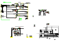
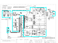
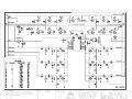
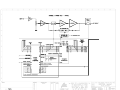
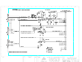
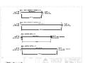
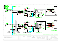
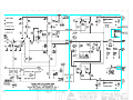
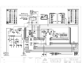
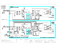
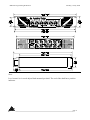
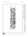
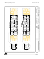
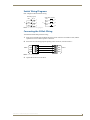
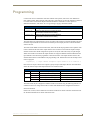
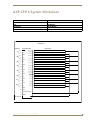
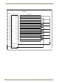
SERVICE INFORMATION
RMa750
POWER AMPLIFIER
CONTENTS:
SCHEMATIC DIAGRAMS
Australian Monitor
1 Clyde Street, Silverwater NSW 2128 Australia
+61 2 9647 1411
www.australianmonitor.com.au
149 Beaconsfield Street,
Silverwater. NSW 2128
Phone: 61 2 9647 1411
Fax: 61 2 9748 2537
RMA750 Overview
Following is an overview of the RMa750 6 channel amplifier including installation and
programming aspects when using:
1) CRESTRON CNPI/ CPI-16B Custom Panel Interface card.
2) AMX AXP-CPI16 Custom Panel Interface card.
These cards are able to accept up to 16 inputs from the amplifier and the cards also have 16 outputs
which can be used to control a number of aspects of the amplifier.
In addition to the standard amplifier (KMa750), we add a control system to amplifier interface. This
interface takes various analogue and status signals within the amplifier and converts them to a logic
level (which is buffered) which can then be interpreted by the custom interface cards for processing
by the control system.
It is important to note that the use of the Crestron/AMX system in relation to the amplifiers is a
supervisory one. On this basis, the normal operation of the amplifier is not dependant on the control
system at all. The control system merely monitors various operational aspects of the amplifier and
reports any faults to the system where appropriate action can be taken, either by an operator, a
program or internally within the amplifier (which can be fed back to the control system).
Ultimately it is felt the system should operate as a fault monitoring system which can/ should/ will
isolate offending channels, report to the system and allow for redundancy aspects if required.
Due to the 6 channels of the RMa and the limit of 16 channels of the Panel Interface cards, an
overall fault detection circuit for each channel has been employed and is referred to as the input to
output (in/out) fault detect circuit.
The input to output fault detection circuit is very broad in its detection ability and has to be a two
way type of detector. Simplified, the fault may be input signal but no output or, output with no
input signal. Any difference between input or output has to be considered as a fault and reported to
the system.
The detection circuitry is basically a differential type circuit which null’s input voltage against
output voltage. The output of the amplifier is applied to the differentiating circuit without any
compensation. The input signal is applied to the circuit with compensation to emulate the
bandwidth and phase response the amplifier. The circuit is full amplifier bandwidth.
Any deviation/difference of signal, other than the fixed input to output gain of the amplifier and a
small window of tolerance within the detection circuitry, will output a signal to a micro on the
amplifier interface for analysis. The in/out detector will show any fault including, D.C supply faults
(post pre-amp when signal is applied), D.C. on the output, oscillation, abnormally high noise (that is
not input born), a muted amplifier, various circuit failures, bad connections, sustained clipping etc.
The circuit does not need signal to alert the system if the amplifier is outputting a signal with no
input signal applied such as D.C., oscillation or out of specification noise. This then also doubles up
RMa750 Programming Definitions
Monday, 10 July 2000
as an early warning system as well. A fault from the in/out detect circuit will pass through an
internally selectable link which will either have the amplifier disconnect the offending channels
relay or have the program (via the control system) open the output relay of the offending channel.
The biggest problem for in/out detect is that clipping is essentially an input to output fault and the
reality is that transients (regardless of preceding signal processing) will generate an in/out fault due
to clipping. The micro on the amplifier interface has been programmed to allow a certain amount of
clipping to occur before reporting a fault. A considerable amount of time was spent to come up with
a suitable routine that took into consideration the ballistics of the status indicator, frequency and
ultimately the power handling ability of speakers envisaged to be used within the installation.
Power
The power for the CNPI/ CPI cards is sourced externally from the amplifiers and is required to be
supplied by the CRESTNET II/AXLink network. Though most of the interfacing to the cards is
powered internally by the amplifier and provides very little loading to the network, there is some
obvious loading that should be considered.
1) To enable the use of a remote power up/down facility, the CNPI/ CPI card has to switch a
high current relay within the amplifier.
2) The indicator for Remote Power enable/standby requires power from the CRESTNET
network.
We should consider 1mA per input and output, 20mA for the Remote Power LED, 40 mA for the
remote power relay on a Crestron system and 80mA for the remote power relay on an AMX system.
The Quiescent current draw of the CNPI card is approximately 100mA and 25mA on a CPI card,
thus a total of around 200mA minimum should be allowed for per CNPI/ CPI card within this
system. The loading of all the CNPI/ CPI cards for the amplifier system could be substantial and the
high level of current can cause substantial voltage drops over long cable lengths so booster type
power supplies should be located close to the amplifiers to minimise insertion loss type problems.
Ground
Grounding for the system is crucial. The amplifier has many ground schemes, one for mains power
and the high current outputs, one for input signal, one for pre-amps and a separate one for the
control system to amplifier interface. The control system earth connecting to each amplifier is not
connected internally to the amplifiers grounding schemes. The CNPI/ CPI card is resistively
isolated to the amplifier and the amplifier’s interface. The control system earth/ground must be at
the same ground potential as the amplifiers. A Technical type earth must be near the amplifiers and
the system should attain “STAR” grounding to this point!!!! Make sure you earth the booster power
supplies - they are not to be allowed to float. Ensure this before anything is ever turned on!!!!!!!
NOTE: If Signal ground lifting is to be used, suitable shielding of the input still needs to be
maintained. If Pin-1 on the interconnecting XLR (source equipment) is all you are relying on, you
may be in trouble as the source may not be providing a true ground for the shield (you should check
this out). You must ensure proper shielding.
The amplifier is supplied with a 4 pin Phoenix type data connector (similar to the ones Crestron and
AMX utilise). We will be supplying the connecting in line plug as well. The connectors are Phoenix
branded where the panel mount male socket is a: DFK-MSTB 2.5/4-G-5.08,
page 2
RMa750 Programming Definitions
and the in line female plug is a:
Monday, 10 July 2000
MSTB 2.5/4-ST-5.08
Due to these companies wanting to look a little bit different, the wiring for the AXlink buss and the
Crestnet buss is exactly opposite. To avoid adding extra cost and dedicated panels for each system
we have included both wiring legends on the back panel and the orientation of the connector
displays the appropriate legend.
Above the connector is a field where the ADDRESS / ID CODE of each amplifier will be marked.
As the Custom panel interface cards are internally fitted we need to set these address’s / codes
during manufacture of the RMa units. Please provide us with this information at your earliest.
A spreadsheet (RMa_PROG.XLS) of operational and control parameters is attached to aid
programming of the system.
Channel assignments re CNPI/ CPI cards.
NOTE: High = off and Low = on.
INPUTS
Input to Output faults (normally high)
Channels 1 to 6 monitor Input to Output faults.
Channel 1 = Channel 1 of the amplifier
Channel 2 = Channel 2 of the amplifier
Channel 3 = Channel 3 of the amplifier
Channel 4 = Channel 4 of the amplifier
Channel 5 = Channel 5 of the amplifier
Channel 6 = Channel 6 of the amplifier
The amplifier’s interface simply monitors that the input to output gain and signal integrity is the
same. If it is to vary then the CNPI/ CPI input for the offending channel will flag the system. The
in/out detector will show any fault including, D.C quiescent faults (post pre-amp), D.C. on the
output, Oscillation, abnormally high noise (that is not input born), a muted amplifier, various circuit
failures, bad connections, clipping etc,etc. The circuit is not sensitive to gain alteration via the front
panel attenuator. An input to output fault has to be maintained before the system is flagged. This is
accomplished by oversampling by the internal micro which will then latch the offending channels
CNPI/ CPI input. An input to output fault should automatically disconnect the offending channel.
This can be accomplished two ways.
1) The system is alerted to the fault and takes action by opening the offending channels
output speaker relay,
or
2) The system is alerted to the fault but the amplifier has automatically opened the relay of
the offending channel.
page 3
RMa750 Programming Definitions
Monday, 10 July 2000
A 2 pin header on the amplifier interface is utilised to select which option is appropriate. We will be
supplying the units with a header link in place which will have the amplifier automatically open the
relay.
Once a fault is detected the CNPI/CPI input is held/latched low. The input will remain in this state
until a reset from the control system is detected (via channel 14 on CNPI/.CPI output).
Amplifier Channel Isolated Indication (normally high)
Channels 7 to 12 monitor speaker output relay status.
Channel 7 = Channel 1 of the amplifier
Channel 8 = Channel 2 of the amplifier
Channel 9 = Channel 3 of the amplifier
Channel 10 = Channel 4 of the amplifier
Channel 11 = Channel 5 of the amplifier
Channel 12 = Channel 6 of the amplifier
This facility is used as a feedback indicator to the control system that the speaker output relays have
actually been opened either automatically by the amplifier or by the control system. This could be
useful when switching in another amplifier channel (as back up) to the speaker feed of the isolated
channel.
Fan Speed Detect
Channel 13 (on CNPI/ CPI card) is used to indicate to the system if the cooling fans are on low
speed or at high speed. If the fans are at low speed Channel 13 will be low, If they are at high speed
then Channel 13 will be high. Low will be the default position. If after a period of time the
amplifier was switching to high speed too soon, then this may indicate the need to unblock the air
intake grilles or the load has a fault and is drawing extreme power from the amplifier etc.
Thermal Detect.
Channel 14 is used to indicate if the amplifier has gone thermal. The input will be normally high
and will go low when the amplifier has thermalled.
In the thermalled state all amplifier channels are muted internally by the amplifier. The channels
will remain muted until the heatsink temperatures have reduced by approximately 20oC after which
all channels will automatically un-mute and return to normal operation.
page 4
RMa750 Programming Definitions
Monday, 10 July 2000
Remote Power Select.
Channel 15 is used to indicate to the system that the rear panel switch on the amplifier has been
engaged to enable remote power up / power down of the amplifier.
High = not selected / not enabled,
Low = selected / enabled.
This feature is powered by the Crestnet/AXlink network.
The switch on the back panel will do several functions.
1) It tells the system it is engaged
2) It will indicate on the front panel of the amplifier that it is engaged
3) routes the control system power to feed a relay that will act as the on/off switch.
The problem with remote on/off power is that when you are physically at the amplifier you may
want control of the amplifier and not to be locally locked out. If you have not enabled remote
power, the front panel on/off switch will work as normal. If remote power is enabled and the system
has switched the amplifier on, the front panel switch will not turn the amplifier off. If you require
the ability to turn the amplifier off locally then you will have to remove the data cable to the
amplifier or disengage the remote power switch.
Unit-Ready/On-Line
Channel 16 has been used to indicate to the system that the amplifier is powered up and ready for
operation. Low = ready for operation. High = powered down or not ready and thus any activity
from the amplifier’s CNPI/ CPI card should be ignored as the amplifier may be establishing itself
after its initial power up. High states can indicate mains failure to the amplifier due to a tripped
mains breaker or failed internal power supply etc.
To play safe once the system has detected a Unit-Ready/On-Line signal from the amplifier it should
do a momentary A.C. Fault Detect Reset (output channel 14). This removes the possibility of the
micro on the interface being latched/locked up, due to not being fully discharged (leakage from
control system) when the amplifier has been powered down.
Combinations of the Unit-Ready/On-Line state and the remote power enable will indicate whether
the amplifier has actually been turned off, has not been turned on or a failure has occurred.
Establishment.
The following is typical of the events as the amplifier powers up.
Inrush Current Suppression.
0.5 seconds
Speaker output relay closure
1 second
Amp Ready Indicator
3 seconds
Input Signal un-mute
4 seconds
Execution of micro Instructions
5 seconds
By the time the micro on the interface is ready to execute its instructions all operating aspects of the
amplifier have been fully established.
page 5
RMa750 Programming Definitions
Monday, 10 July 2000
OUTPUTS.
Channel Mutes (normally high and thus un-muted)
Channels 1 to 6 act as mute control.
Channel 1 = Channel 1 of the amplifier
Channel 2 = Channel 2 of the amplifier
Channel 3 = Channel 3 of the amplifier
Channel 4 = Channel 4 of the amplifier
Channel 5 = Channel 5 of the amplifier
Channel 6 = Channel 6 of the amplifier
Sending these channels low will mute the appropriate amplifier channel.
For whatever reason you may want to mute a channel or channels. It must be noted that in muting a
channel (with signal applied) you will invoke the input to output fault circuitry. The mute is internal
in the amplifier and alters the amplifiers input to output gain thus invoking a false fault report. The
program should be written to ignore Input to Output faults in this state.
A diagnostics mode could be instigated where to check the integrity of the in/out fault detect circuit
you deliberately mute the amplifier to invoke the fault.
NOTE: If the amplifier goes into thermal protect mode then the muting of the channels by the
amplifier’s internal circuitry will also invoke an in/out fault per channel. The amplifier going into
thermal protect may be considered as an operational mode or state and is not necessarily a fault.
Now comes all the awkward bits and where you have to make decisions. As you can see, a lot of the
monitoring and control aspects interact. This interaction can be used to make decisions for
redundancy aspects but complicates programming and creates a lot of activity on the buss and may
slow up response time.
As you have seen, if the amplifier goes thermal or if a channel is remotely muted than an in/out
fault is reported. You can ignore or use the in/out fault report to the system and deal with them any
way you wish but you must remember that a fault has to be reset or it remains a fault.
We will include an ability on the interface (which will be selectable) to not have in/out faults report
to the system when the amplifier is in thermal protect mode or when a system command mutes a
channel or channels of the amplifier and /or have the reset feature automated by the amplifier when
recovering from a thermalled state or system un-muting.
You are employing the use of the amplifier and we are happy to have your input here as to what the
default states should be for your installation.
Channel Relays (normally high and thus load connected)
Channels 7 to 12 can be used to open the relays of individual channels.
Channel 7 = Channel 1 of the amplifier
Channel 8 = Channel 2 of the amplifier
Channel 9 = Channel 3 of the amplifier
Channel 10 = Channel 4 of the amplifier
Channel 11 = Channel 5 of the amplifier
Channel 12 = Channel 6 of the amplifier
page 6
RMa750 Programming Definitions
Monday, 10 July 2000
Channels 13 and 16 of the CNPI/ CPI are not currently being used.
A.C. Fault Detect Reset. (normally high)
Channel 14 is used to reset the micro on the interface. The micro will latch an input relative to the
channel reporting an input to output fault. To enable the operator or program to verify a sustained
fault condition, a reset has been included to reset the micro so as to un-latch all inputs and re-start
the interrogation program of the micro. Sending this output low will reset all channels of the
applicable amplifier. This is to be a momentary action only as holding this pin low overides the
micro on the amplifier to control system interface.
Input to output faults should be interrogated/verified with the offending channel’s relay open (so as
not to kill your load in case it is a really big fault). I.E. If a in/out fault is reported, force the channel
relay open (to override the resetting of the relay), reset the amplifier and see if the fault occurs
again, if not, close the relay - you don’t even have to leave your chair.
Remote Power.
Channel 15 has been assigned to provide the control signal to initiate a remote “MAINS” power up
of the amplifier. If the amplifier has been enabled for remote power up/down by engaging the rear
panel switch then channel 15 going low will turn the amplifier on. Channel 15 going high will turn
the amplifier off. Channel 15 controls a mains switching relay which is powered by the control
system network. A LED on the front panel of the amplifier indicates that remote power has been
enabled and this is reflected at the control screen via input channel 15 as well. The front panel
mains on/off switch on the amplifier will override the remote system for power on if it is in the
“ON” position.
If the “UNIT-READY” input is low (input channel 16) then if the “remote power on” has not been
selected but the amplifier has been manually turned on via the front panel switch, the remote power
indicator should be ignored in some way.
Obviously there will be numerous questions and “what ifs” arise from the above. Various input
from all parties involved will ultimately create your final program.
3 drawings have been included with this communique which show the layout and legends of the
front and Back panels along with an installation drawing showing major dimensions.
Due to the extended class-A MOSFET output stage of the RMa750, the quiescent (idle) mains
current draw is about 1 Amp, the mains fuse is rated at 5 amps and current peaks over 8 amps can
be produced. The unit is a 2RU 19” rack mounting unit. Mains termination is via a standard IEC
connector, all inputs are 3 pin female XL type connectors where Pin-2 = Hot. Speaker termination
is via a heavy duty 3/4” (19mm) spaced binding posts which will accept cable up to 4mm2.
Yours Sincerely,
Stuart McLean.
Design & Product Engineer.
[email protected]
www.audiotelex.com.au
www.australianmonitor.com.au
page 7
RMa750 Programming Definitions
Monday, 10 July 2000
Note:
Level control is via a tool adjust flush mounted pot shaft. The end of the shaft has a position
indicator.
page 8
RMa750 Programming Definitions
Monday, 10 July 2000
page 9
RMa750 Programming Definitions
Monday, 10 July 2000
page 10
Operation/Reference Guide
AXP-CPI16
16-Channel Custom Panel Interface
Custom Panel Interfaces
Document ID: 038-004-1334
Last Revised: 8/16/2006
AMX Limited Warranty and Disclaimer
AMX warrants its products to be free of defects in material and workmanship under normal use for three (3) years from
the date of purchase from AMX, with the following exceptions:
•
Electroluminescent and LCD Control Panels are warranted for three (3) years, except for the display and touch
overlay components that are warranted for a period of one (1) year.
•
Disk drive mechanisms, pan/tilt heads, power supplies, and MX Series products are warranted for a period of one
(1) year.
•
AMX Lighting products are guaranteed to switch on and off any load that is properly connected to our lighting
products, as long as the AMX Lighting products are under warranty. AMX does guarantee the control of dimmable
loads that are properly connected to our lighting products. The dimming performance or quality cannot be
guaranteed due to the random combinations of dimmers, lamps and ballasts or transformers.
•
Unless otherwise specified, OEM and custom products are warranted for a period of one (1) year.
•
AMX Software is warranted for a period of ninety (90) days.
•
Batteries and incandescent lamps are not covered under the warranty.
This warranty extends only to products purchased directly from AMX or an Authorized AMX Dealer.
All products returned to AMX require a Return Material Authorization (RMA) number. The RMA number is obtained
from the AMX RMA Department. The RMA number must be clearly marked on the outside of each box. The RMA is
valid for a 30-day period. After the 30-day period the RMA will be cancelled. Any shipments received not consistent
with the RMA, or after the RMA is cancelled, will be refused. AMX is not responsible for products returned without a
valid RMA number.
AMX is not liable for any damages caused by its products or for the failure of its products to perform. This includes any
lost profits, lost savings, incidental damages, or consequential damages. AMX is not liable for any claim made by a
third party or by an AMX Dealer for a third party.
This limitation of liability applies whether damages are sought, or a claim is made, under this warranty or as a tort claim
(including negligence and strict product liability), a contract claim, or any other claim. This limitation of liability cannot
be waived or amended by any person. This limitation of liability will be effective even if AMX or an authorized
representative of AMX has been advised of the possibility of any such damages. This limitation of liability, however, will
not apply to claims for personal injury.
Some states do not allow a limitation of how long an implied warranty last. Some states do not allow the limitation or
exclusion of incidental or consequential damages for consumer products. In such states, the limitation or exclusion of
the Limited Warranty may not apply. This Limited Warranty gives the owner specific legal rights. The owner may also
have other rights that vary from state to state. The owner is advised to consult applicable state laws for full
determination of rights.
EXCEPT AS EXPRESSLY SET FORTH IN THIS WARRANTY, AMX MAKES NO OTHER WARRANTIES,
EXPRESSED OR IMPLIED, INCLUDING ANY IMPLIED WARRANTIES OF MERCHANTABILITY OR FITNESS FOR
A PARTICULAR PURPOSE. AMX EXPRESSLY DISCLAIMS ALL WARRANTIES NOT STATED IN THIS LIMITED
WARRANTY. ANY IMPLIED WARRANTIES THAT MAY BE IMPOSED BY LAW ARE LIMITED TO THE TERMS OF
THIS LIMITED WARRANTY.
Table of Contents
Table of Contents
Product Information ...........................................................................................1
Specifications............................................................................................................ 1
Installation ..........................................................................................................5
Mounting Dimensions ............................................................................................... 5
Setting the AXlink Device Number ........................................................................... 6
Preparing/connecting captive wires ................................................................................ 6
Connecting the Two 20-pin Headers ........................................................................ 6
Switch Wiring Diagrams............................................................................................ 7
Connecting the AXlink Wiring................................................................................... 7
Programming ......................................................................................................9
Testing the Unit ...................................................................................................... 10
AXP-CPI16 System Worksheet .........................................................................11
AXP-CPI16 16-Channel Custom Panel Interface
i
Table of Contents
ii
AXP-CPI16 16-Channel Custom Panel Interface
Product Information
Product Information
The AMX AXP-CPI16 16 Channel Custom Panel Interface Board (FIG. 1) simplifies the process of
creating custom control panels for Axcess systems. Providing contact closure inputs and feedback
outputs for up to 16 buttons, the miniature PC board contains a 20-pin header for ribbon cable
installation or for direct mounting to a printed circuit board.
AXlink
Connector
Pin 1
20-Pin Header P3
Connect this side to the ribbon cable
Pin 1
Device
DIP Switch
AXlink Status LED
-Pin Header P2
onnect this side to the ribbon cable
Connect this side to
the PC board
FIG. 1 AXP-CPI16 components
Specifications
The following table lists product specifications for the AXP-CPI16.
AXP-CPI16 Specifications
Dimensions (HWD)
Power
2.75" x 1.75" x 0.062" (69.90 mm x 44.50 mm x 1.557 mm)
• Input voltage: 12 VDC (nominal)
• Current draw: 25mA
Inputs
16 closure inputs with a common ground (GND)
Outputs
16 open-collector outputs, acting as switch to ground, up to 100 mA DC each for:
• Board is not to supply more than 750 mA of +12V total.
• Small incandescent lamps
• LED indicators - with series resistor (1K for 12 VDC)
• Relays - with DC coil
AXlink Connector
A 4-pin (male) connector attached to a four-wire cable which sends control data from the
Axcess CardFrame to the AXP-CPI16.
Headers
Two 20-pin headers included for ribbon cables (up to 100 feet each) or for mounting
directly to a PC board.
AXP-CPI16 16-Channel Custom Panel Interface
1
Product Information
AXP-CPI16 Specifications (Cont.)
AXlink Status LED
Indicates AXlink communication status as follows:
• One blink per second communication is functioning.
• Two blinks per second devices specified in the master program do not match the
specified devices found.
• Three blinks per second indicate an AXlink communication error.
• Full-on indicates there is no AXlink control or activity (but power is on), or the Axcess
program is not loaded.
2
Device DIP Switch
8-position DIP switch sets AXlink device ID.
Cables
Two 3-foot (91.4 cm) ribbon cables each with a female 20-pin header.
AXP-CPI16 16-Channel Custom Panel Interface
Product Information
OFF
OFF
ON
ON
AXP-CPI16 16-Channel Custom Panel Interface
1 2 3 4 5
6 7 8
3
Product Information
4
AXP-CPI16 16-Channel Custom Panel Interface
Installation
Installation
Mounting Dimensions
LH
B
B
AA
A
A
C
C
AXlink
AXlink
GND
PWRAXP
AXP AXM
GND
L
J
P1
1
1 22
P1
PWR AXM
P3
P3
Top View
(Component Side)
Top View
(Component Side)
D
D
E
E
P2
P2
2
1
19
19 20
20
MM
20
20
19
19
J
G
F
F
KG
H
K
min
min
FIG. 1 AXP-CPI16 mounting dimensions
Mounting Dimensions
Item Inch
mm
Item Description
A
0.10
2.50
K
B
1.75
44.50 L
0.125 Inch (3.2 mm) mounting holes for #4-40 (3 mm) screws
C
1.55
39.40 M
P3 20-Pin Header .025 inch (6 mm) square pins, .1 inch (2.4 mm) typical
spacing
D
2.75
69.90
E
2.55
64.80
F
0.35
8.90
G
0.23
5.80
H
0.438 11.10
J
0.93
P2 20-Pin Header .025 inch (6 mm) square pins, .1 inch (2.4 mm) typical
spacing
23.6
AXP-CPI16 16-Channel Custom Panel Interface
5
Installation
Setting the AXlink Device Number
The 8-position device DIP switch defines the AXP-CPI16 as an AXlink device. It can be one of 255
devices in the Axcess Control System. Set the device number with the total value of all ON (down)
positions. As an example, the device DIP switch shown below defines device number 129 (1+128=129).
Position 1 2 3 4 5
Value
6
7
8
OFF
OFF
1 2 4 8 16 32 64 128
ON
ON
1 2 3 4 5
6 7 8
AMX standard device numbers are assigned as follows:
Cards are 1 through 25.
Boxes are 96 through 127.
Panels are 128 through 255.
Preparing/connecting captive wires
1. Strip 0.25 inch of wire insulation off all wires.
2. Insert each wire into the appropriate opening on the connector according to the wiring diagrams and
connector types described in this section.
3. Tighten the screws to secure the wires. Do not tighten the screws excessively; doing so may strip the
threads and damage the connector.
Connecting the Two 20-pin Headers
The following chart notes the pinouts of the two 20-pin headers for P2 and P3.
AXP-CPI16 P2/P3 Pinouts
P2
P3
Pin Function Pin Function Pin Function Pin Function
1
Output 1
11
GND
1
Output 9
11
GND
2
Output 2
12
GND
2
Output 10
12
GND
3
Output 3
13
Input 1
3
Output 11
13
Input 9
4
Output 4
14
Input 2
4
Output 12
14
Input 10
5
Output 5
15
Input 3
5
Output 13
15
Input 11
6
Output 6
16
Input 4
6
Output 14
16
Input 12
7
Output 7
17
Input 5
7
Output 15
17
Input 13
8
Output 8
18
Input 6
8
Output 16
18
Input 14
9
GND
19
Input 7
9
GND
19
Input 15
10
PWR
20
Input 8
10
PWR
20
Input 16
Pin 10 provides +12 VDC power from AXlink bus. Add 1K series resistors when using AXP-CPI16 with
LED indicators receiving 12 VDC power from Pin 10.
6
AXP-CPI16 16-Channel Custom Panel Interface
Installation
Switch Wiring Diagrams
FIG. 2 diagrams LED and Switch wiring.
LED Wiring (Typical)
10
LED 1
1K
LED 2
1K
LED 3
1K
Switch Wiring (Typical)
SW 1
1
2
12
3
SW 2
SW 3
13
14
15
FIG. 2 LED and switch wiring diagrams
Connecting the AXlink Wiring
To install the AXlink data/power bus wiring.
1. Strip 0.25 inch off the wire insulation for all four wires. If the wire is 20 AWG or less, fold the
exposed wire over to obtain a positive connection.
2. Insert each wire into the appropriate opening on the connector, as shown in FIG. 3.
AXlink
PWR
PWR
AXP
AXP
AXM
AXM
GND
GND
Device
FIG. 3 AXlink wiring diagram
3. Tighten the screws to secure the fit.
AXP-CPI16 16-Channel Custom Panel Interface
7
Installation
8
AXP-CPI16 16-Channel Custom Panel Interface
Programming
Programming
Use the same Axcess commands as with other AXlink control panels, such as the AXU-MSP series
mini-softwire panels. When using the AXP-CPI16 as a control device, use On, Off, and Pulse commands
to control sources connected to outputs and Push and Release commands to receive inputs. For
additional information, refer to the Axcess Programming Language instruction manual.
Send_Commands
Command
Description
Causes the AXP-CPI16 to be in Status-On Mode.
'STATUS-ON'
This command overrides the mode setting.
Causes the AXP-CPI16 to be in Status-Off Mode.
'STATUS-OFF'
This command overrides the mode setting.
The AXP-CPI16 uses input channels to report user input on the contacts or switches attached to the input
terminals. Output channels are used to turn on the lamp or LED display devices to indicate the button
status to the user.
The AXP-CPI16 default mode is STATUS-OFF, and in this mode the programmer cannot poll the AXPCPI16 to determine the state of the output channel. This is because in this mode the output and input
channels use the same number assignments. Inputs are sent by the AXP-CPI16 only as input changes.
When set for STATUS-ON mode the output channels are assigned a different channel number than the
input channels. This allows the programmer to monitor the status of an output channel. However the
channel offset must be accommodated in the programming code. Statements such as this example can be
used in a program.
IF[CPI16,25]
(* output channel assigned to input channel 9 on P3 connector *)
Each of the two 20-pin connectors is assigned a group of 8 input and output channels. The table below
shows the relation of input and output channels in the STATUS modes.
Input/Output STATUS Mode
Mode
Connector
Inputs
Outputs
STATUS-OFF (default)
STATUS-ON
P2
Chan 1-8 (Push/Release only)
Chan 1-8 (On/Push/Off/Release)
P3
Chan 9-16 (On/Off only)
Chan 17-24 (On/Off)
P2
Chan 1-8 (Push/Release only)
Chan 9-16 (On/Push/Off/Release)
P3
Chan 9-16 (On/Off only)
Chan 25-32 (On/Off)
The AXP-CPI16 may be configured to default to STATUS-ON mode using the following method. The
commands can force a change to the mode no matter what default mode is configured for the device.
STATUS-ON Mode:
Remove R7 (1K ohm) resistor OR short across R8 for STATUS-ON mode. Firmware remains the same
for standard and STATUS-ON mode AXP-CPI16 units.
AXP-CPI16 16-Channel Custom Panel Interface
9
Programming
Testing the Unit
If you have programmed the Axcess software, load the program into a PC connected to the control
system Master port. See Programming on page 4.
1. Push switches connected to the AXP-CPI16.
2. Look at the lower left of the Axcess screen to verify that the correct device and channel numbers are
displayed.
3. Check for the appropriate feedback (as provided by the Master Controller program).
10
AXP-CPI16 16-Channel Custom Panel Interface
AXP-CPI16 System Worksheet
AXP-CPI16 System Worksheet
Dealer ID
Date
Dealer
PO Number
Job
SO Number
Description
Serial Number
Rev Number
Device Number
HEADER P2
Channel
1
2
3
20-PIN HEADER
1
13
2
14
3
15
4
4
5
16
5
17
6
6
7
18
7
19
8
8
20
In
In
Out
Out
In
In
Out
Out
In
In
Out
Out
In
In
Out
Out
In
In
Out
Out
In
In
Out
Out
In
In
Out
Out
In
In
9
N/C
N/C
11
N/C
N/C
10
+12
VDC PWR
+12VDC
PWR
12
PinNumber
Number
Pin
FUNCTION
Out
Out
GND
GND
AXP-CPI16 16-Channel Custom Panel Interface
11
AXP-CPI16 System Worksheet
HEADER P3
Channel
9
10
11
1
13
2
14
3
15
4
12
16
13
17
5
6
14
15
18
7
19
8
16
20
20-PIN HEADER
FUNCTION
Out
Out
In
In
Out
Out
In
In
Out
Out
In
In
Out
Out
In
In
Out
Out
In
In
Out
Out
In
In
Out
Out
In
In
Out
Out
In
In
9
N/C
N/C
11
N/C
N/C
10
+12
VDC PWR
+12VDC
PWR
12 GND
GND
Pin
Number
Pin Number
12
AXP-CPI16 16-Channel Custom Panel Interface
System Worksheet
AXP-CPI16 16-Channel Custom Panel Interface
13
It’s Your World - Take Control™
3000 RESEARCH DRIVE, RICHARDSON, TX 75082 USA • 800.222.0193 • 469.624.8000 • 469-624-7153 fax • 800.932.6993 technical support • www.amx.com
038-004-0334 8/06
©2006
AMX. All rights reserved. AMX and the AMX logo are registered trademarks of AMX. AMX reserves the right to alter specifications without notice at any time.