1
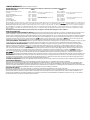
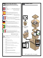
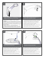
© 2009-2010, Moog Videolarm, Inc. All Rights Reserved
RHW75
Vandal- Resistant Rugged (Outdoor Dome Housing)
www.videolarm.com
Installation and Operation Instructions for the following models:
RHW75C2N
RHP75C2N
IRHW75C2N
IRHP75C2N
RHW75C2NE
IP Network Ready 7” Vandal-Resistant Outdoor dome housing with wall mount, rugged cast
aluminum top and polycarbonate clear dome, with 24VAC input, heater/blower, for an IP
Network PTZ camera, 120 to 24VAC transformer.
IP Network Ready 7” Vandal-Resistant Outdoor dome housing with pendent mount, rugged cast aluminum top and polycarbonate clear dome, with 24VAC input, heater/blower, for an IP Network
PTZ camera, 120 to 24VAC transformer.
IP Network Ready 7” Vandal-Resistant Indoor dome housing with wall mount, rugged cast aluminum top and polycarbonate clear dome, with 24VAC input, heater/blower, for an IP Network PTZ camera, 120 to 24VAC transformer.
IP Network Ready 7” Vandal-Resistant Indoor dome housing with pendent mount, rugged cast aluminum top and polycarbonate clear dome, with 24VAC input, heater/blower, for an IP
Network PTZ camera, 120 to 24VAC transformer.
IP Network Ready 7” Vandal-Resistant Outdoor dome housing with wall mount, rugged cast
aluminum top and polycarbonate clear dome, with 24VAC input, heater/blower, for an
IP Network PTZ camera, 120 to 24VAC transformer. (European Model)
Before attempting to connect or operate this product, please read these instructions completely.
CERTIFIED
81-IN5309
07-26-2010
IMPORTANT SAFEGUARDS
1
Read these instructions.
2
Keep these instructions.
3
Heed all warnings
4
Follow all instructions.
5
Do not use this apparatus near water.
6
Clean only with damp cloth.
7
SAFETY PRECAUTIONS
CAUTION
RISK OF ELECTRIC SHOCK
DO NOT OPEN
CAUTION: TO REDUCE THE RISK OF
ELECTRIC SHOCK, DO NOT REMOVE
COVER ( OR BACK). NO USER- SERVICEABLE PARTS INSIDE. REFER SEVICING
TO QUALIFIED SERVICE PERSONNEL.
Do not block any of the ventilation openings. Install in accordance with the
manufacturers instructions.
8
9
Cable Runs- All cable runs must be within permissible distance.
Mounting - This unit must be properly and securely mounted to a supporting
structure capable of sustaining the weight of the unit.
Accordingly:
a. The installation should be made by a qualified installer.
b. The installation should be in compliance with local codes.
c. Care should be exercised to select suitable hardware to install the unit, taking into
account both the composition of the mounting surface and the weight of the unit.
10 Do not install near any heat sources such as radiators, heat registers, stoves, or other
apparatus ( including amplifiers) that produce heat.
11 Do not defeat the safety purpose of the polarized or grounding-type plug. A
polarized plug has two blades with one wider than the other. A grounding type
plug has two blades and a third grounding prong. The wide blade or the third
prong are provided for your safety. When the provided plug does not fit into your
outlet, consult an electrician for replacement of the obsolete outlet.
12 Protect the power cord from being walked on or pinched particularly
at plugs,
convenience receptacles, and the point where they exit from the apparatus.
13 Only use attachment/ accessories specified by the manufacturer.
14 Use only with a cart, stand, tripod, bracket, or table specified by the manufacturer,
or sold with the apparatus. When a cart is used, use caution when moving the cart/
apparatus combination to avoid injury from tip-over.
15 Unplug this apparatus during lighting storms or when unused for long periods of time.
16 Refer all servicing to qualified service personnel. Servicing is required when the
apparatus has been damaged in any way, such as power-supply cord or plug is
damaged, liquid has been spilled of objects have fallen into the apparatus, the
The lightning flash with an arrowhead symbol,
within an equilateral triangle, is intended to
alert the user to the presence of non-insulated
“dangerous voltage” within the product’s
enclosure that may be of sufficient magnitude
to constitute a risk to persons.
Este símbolo se piensa para alertar al usuario a la presencia
del “voltaje peligroso no-aisIado” dentro del recinto de los
productos que puede ser un riesgo de choque eléctrico.
Ce symbole est prévu pour alerter I’utilisateur à la presence
“de la tension dangereuse” non-isolée dans la clôture de
produits qui peut être un risque de choc électrique.
Dieses Symbol soll den Benutzer zum Vorhandensein der
nicht-lsolier “Gefährdungsspannung” innerhalb der
Produkteinschließung alarmieren die eine Gefahr des
elektrischen Schlages sein kann.
Este símbolo é pretendido alertar o usuário à presença “di
tensão perigosa non-isolada” dentro do cerco dos produtos
que pode ser um risco de choque elétrico.
Questo simbolo è inteso per avvertire I’utente alla presenza
“di tensione pericolosa” non-isolata all’interno della
recinzione dei prodotti che può essere un rischio di scossa
elettrica.
apparatus has been exposed to rain or moisture, does not operate normally, or
has been dropped.
Be sure to periodically examine the unit and the supporting structure to make sure that the integrity
of the installation is intact. Failure to comply with the foregoing could result in the unit separating
from the support structure and falling, with resultant damages or injury to anyone or anything struck
by the falling unit.
UNPACKING
Unpack carefully. Electronic components can be
damaged if improperly handled or dropped. If an item
appears to have been damaged in shipment, replace
it properly in its carton and notify the shipper.
Be sure to save:
1 The shipping carton and packaging material.
They are the safest material in which to make future
shipments of the equipment.
2 These Installation and Operating Instructions.
SERVICE
If technical support or service is needed, contact us at
the following number:
TECHNICAL SUPPORT
AVAILABLE 24 HOURS
1- 800 - 554 -1124
The exclamation point within an equilateral
triangle is intended to alert the user to
presence of important operating and
maintenance (servicing) instructions in the
literature accompanying the appliance.
Este símbolo del punto del exclamation se piensa para
alertar al usuario a la presencia de instrucciones importantes
en la literatura que acompaña la aplicación.
Ce symbole de point d’exclamation est prévu pour alerter
l’utilisateur à la presence des instructions importantes dans
la littérature accompagnant l’appareil.
Dieses Ausruf Punktsymbol soll den Benutzer zum
Vorhandensein de wichtigen Anweisungen in der Literatur
alarmieren, die das Gerät begleitet.
Este símbolo do ponto do exclamation é pretendido alertar o
usuário à presença de instruções importantes na literatura
que acompanha o dispositivo.
Questo simbolo del punto del exclamaton è inteso per
avvertire l’utente alla presenza delle istruzioni importanti nella
letteratura che accompagna l'apparecchio.
LIMITED WARRANTY FOR VIDEOLARM INC. PRODUCTS
VIDEOLARM INC. warrants this Product to be free from defects in material or workmanship,as follows:
PRODUCTCATEGORY
PARTS
LABOR
All Enclosuresand Electronics
Five (5) Years
Five (5) Years
Pan/Tilts
Three (3) Years **6 months if used in autoscan
Three (3) Years **6 months if used in autoscan
/tour operation
Poles/PoleEvators
Three (3) Years /tour operation
Three (3) Years
Warrior/Q-View/I.R.Illuminators
Five (5) Years
Five (5) Years
Five (5) Years **6 months if used in autoscan
SView Series
Five (5) Years **6 months if used in autoscan
/tour operation
Controllers
Five (5) Years /tour operation
Five (5) Years
Power Supplies
Five (5) Years
Five (5) Years
AccessoryBrackets
Five (5) Years
Five (5) Years
During the labor warranty period, to repair the Product,Purchaserwill either return the defective product, freight prepaid, or deliver it to Videolarm Inc.
an equal degree of protection with a
Decatur GA.The Productto be repaired is to be returned in either its original carton or a similar package
RMA# (Return Materials Authorization number) displayed on the outer box or packing slip. To obtain a RMA#you must contact our Technical Support
Team at 800.554.1124,extension 101.Videolarm will return the repaired Productfreight prepaid to Purchaser.Videolarm is not obligated to provide
Purchaserwith a substitute unit during the warranty period or at any time. After the applicable warranty period, Purchasermust pay all labor and/or
parts charges.
The limited warranty stated in these product instructions is subject to all of the following terms and conditions:
TERMS AND CONDITIONS
1. NOTIFICATIONOF CLAIMS: WARRANTYSERVICE: If Purchaser believes that the Product is defective in material or workmanship, then written notice
with an explanation of the claim shall be given promptly by Purchaser to Videolarm but all claims for warranty service must be made within the
warranty period. If after investigation Videolarm determines that the reported problem was not covered by the warranty, Purchaser shall pay Videolarm
for the cost of investigating the problem at its then prevailing per incident billable rate. No repair or replacement of any Product or part thereof shall
extend the warranty period as to the entire Product. The
warranty on the repaired part only shall be in
for a period of ninety (90) days
following the repair or replacement of that part or the remaining period of the Product parts warranty, whichever is greater.
2. EXCLUSIVE REMEDY: ACCEPTANCE:Purchaser’s exclusive remedy and Videolarm’s sole obligation is to supply (or pay for) all labor necessary to repair
any Product found to be defective within the warranty period and to supply, at no extra charge, new or rebuilt replacements for defective parts.
3. EXCEPTIONS TO LIMITED WARRANTY: Videolarm shall have no liability or obligation to Purchaser with respect to any Product requiring service
during the warranty period which is subjected to any of the following: abuse, improper use: negligence, accident, lightning damage or other acts
of God (i.e., hurricanes, earthquakes),
failure of the end-user to follow the directions outlined in the product instructions, failure of the
end-user to follow the maintenance procedures recommended by the International Security Industry Organization, written in product instructions,
for regular
or recommended in the service manual for the Product. Furthermore, Videolarm shall have no liability where a schedule is
replacement or maintenance or cleaning of certain parts (based on usage) and the end-user has failed to follow such schedule; attempted repair by
personnel; operation of the Product outside of the published environmental and electrical parameters, or if such Product’s original
(trademark, serial number) markings have been defaced, altered, or removed. Videolarm excludes from warranty coverage Products sold
AS IS and/or WITH ALL FAULTS and excludes used Products which have not been sold by Videolarm to the Purchaser. All software and accompanying
documentation furnished with, or as part of the Product is furnished “AS IS” (i.e., without any warranty of any kind), except where expressly provided
otherwise in any documentation or license agreement furnished with the Product.
4. PROOF OF PURCHASE: The Purchaser’s dated bill of sale must be retained as evidence of the date of purchase and to establish warranty eligibility.
DISCLAIMEROF WARRANTY
EXCEPT FOR THE FOREGOING WARRANTIES, VIDEOLARM HEREBY DISCLAIMS AND EXCLUDES ALL OTHER WARRANTIES, EXPRESS OR IMPLIED,
INCLUDING, BUT NOT LIMITED TO ANY AND/OR ALL IMPLIED WARRANTIES OF MERCHANTABILITY, FITNESS FOR A PARTICULAR PURPOSE AND/OR ANY WARRANTY WITH
REGARD TO ANY CLAIM OF INFRINGEMENT THAT MAY BE PROVIDED IN SECTION 2-312(3) OF THE UNIFORM COMMERCIAL CODE AND/OR IN ANY OTHER COMPARABLE
STATE STATUTE. VIDEOLARM HEREBY DISCLAIMS ANY REPRESENTATIONS OR WARRANTY THAT THE PRODUCT IS COMPATIBLE WITH ANY COMBINATION OF NON-VIDEOLARM
PRODUCTS OR NON-VIDEOLARM RECOMMENDED PRODUCTS PURCHASER CHOOSES TO CONNECT TO PRODUCT.
LIMITATION OF LIABILITY
THE LIABILITY OF VIDEOLARM, IF ANY, AND PURCHASER’S SOLE AND EXCLUSIVE REMEDY FOR DAMAGES FOR ANY CLAIM OF ANY KIND
WHATSOEVER, REGARDLESS OF THE LEGAL THEORY AND WHETHER ARISING IN TORT OR CONTRACT, SHALL NOT BE GREATER THAN THE ACTUAL PURCHASE PRICE OF THE
PRODUCT WITH RESPECT TO WHICH SUCH CLAIM IS MADE. IN NO EVENT SHALL VIDEOLARM BE LIABLE TO PURCHASER FOR ANY SPECIAL, INDIRECT, INCIDENTAL, OR
CONSEQUENTIAL DAMAGES OF ANY KIND INCLUDING, BUT NOT LIMITED TO, COMPENSATION, REIMBURSEMENT OR DAMAGES ON ACCOUNT OF THE LOSS OF PRESENT
OR PROSPECTIVE PROFITS OR FOR ANY OTHER REASON WHATSOEVER.
!
English
Español
Français
Deutsch
Portuguese
Italiano
Electrical Specifications
Contents of Box
RHW75
Power 24VAC
Class 2 Only
24 VAC
92 Watts
Accessories:
Heater: 50 Watts, Blower: 2 Watt
Camera Power: (See Camera Specifications): 40 Watts Max
Tools Required:
.100” Flat Head Screwdriver
Phillips Head Screwdriver
24 VAC
92 Vatios
De Accesorios: Calentador: 50 Watts, Blower: 2 Vatio
Energía De la Cámara fotográfica De : (Véase Las
Especificaciones De la Cámara fotográfica): 40 Vatios
De Herramientas Máximas
Requeridas: Destornillador Principal Phillips Del Destornillador
Principal Plano Del 100"
24 VCA
92 Watts
D'Accessoires : Réchauffeur : 50 Watts, Ventilateur : 2 watts.
Puissance D'Appareil-photo : (Voir Les Caractéristiques
D'Appareil-photo) : 40 Watts De Maximum
Les Outils Ont exigé : Tournevis Principal Phillips De Tournevis
Principal Plat De 100".
24 VAC
92 Watt
Zusatzgerät-: Heizung: 50 Watts, Blower: 2
Watt-Kamera-Energie: (Sehen Sie Kamera-Spezifikationen):
40 Watt Maximale Werkzeug-Erfordert: 100"Flacher
Hauptschraubenzieher-Kreuzkopfhauptschraubenzieher
24 VAC
92 Watts
De Acessórios: Calefator: 50 Watts, Blower: 2 Watt
Poder Da Câmera De : (Veja Especificações Da Câmera):
40 Watts De Ferramentas Máximas Requereram: Chave de
fenda Principal Phillips Da Chave de fenda Principal Lisa Do 100"
Pendent Model
(ONLY)
24 VCA
92 Watt
Di Accessori: Riscaldatore: 50 Watts, Blower: 2 Watt
Alimentazione Della Macchina fotografica Da :
(Veda Le Specifiche Della Macchina fotografica): 40 Watt
Di Attrezzi Massimi Hanno richiesto: Cacciavite Capo "phillips"
Del Cacciavite Capo Piano Del 100"
IRHW75CN (INDOOR ONLY)
!
Indoor Models IFDW75CN/ IFDP75CN Include NO Power
Accessories
International Models FDW75C2NE/ FDP75C2NE Include NO
Power Transformer
24 VAC
No power options provided.
Power required for camera only.
24 VAC
Ningunas opciones de la energía proporcionaron.
Energía requerida para la cámara fotográfica solamente.
*
24 VCA
Option de puissance n'a pas fourni.
Puissance requise pour l'appareil-photo seulement.
24 VAC
Keine Energie Wahlen stellten zur Verfügung.
Energie erfordert für nur Kamera.
24 VAC
Nenhumas opções do poder fornecidas.
Poder requerido para a câmera somente.
24 VAC
Nessun'opzione di alimentazione ha fornito.
Alimentazione richiesta per la macchina fotografica soltanto.
* NOT included with E or 12V models
1
WALL MOUNTING
2
4”-5”
Bracket is designed for 45° conduit fitting (If using the
conduit). Run wire into bracket secure to wall.
• El soporte se diseña para la guarnición del conducto 45° (si usa el
conducto). Funcione con el alambre en el soporte seguro para
emparedar.
• La parenthèse est conçue pour l'ajustage de précision du conduit 45° (si
à l'aide du conduit). Courez le fil dans la parenthèse bloquée pour murer.
• Haltewinkel ist für Befestigung des Rohres 45° bestimmt (wenn das Rohr
verwendet wird). Lassen Sie Draht in den Haltewinkel laufen, der, um zu
ummauern sicher ist.
• O suporte é projetado para o encaixe da canalização 45° (se usando a
canalização). Funcione o fio no suporte seguro para murar.
• La staffa è progettata per il montaggio del condotto 45° (se per mezzo
del condotto). Faccia funzionare il legare nella staffa sicura per murare.
3
Secure lanyard to lanyard clip
Trim incoming control & power wires to 4”- 5”,
for either wall or pendent bracket
• Con seguridad soporte del montaje a emparedar. Tire del cableado
a través del soporte y del ojal de la posición según lo demostrado.
• Solidement parenthèse de bâti à murer. Tirez le câblage par la
parenthèse et le canon isolant de position comme montré.
• Sicher Einfassung Haltewinkel wall. Ziehen Sie Verdrahtung durch
Haltewinkel und Position Gummimuffe, wie gezeigt.
• Firmemente suporte da montagem a wall. Puxe a fiação através do
suporte e do ilhó da posição como mostrado.
• Saldamente staffa del supporto da wall. Tiri i collegamenti tramite la
staffa ed il gommino di protezione di posizione come indicato.
4
Complete ALL wiring connections
• Con seguridad soporte del montaje a emparedar. Tire del cableado
a través del soporte y del ojal de la posición según lo demostrado.
• Con seguridad soporte del montaje a emparedar. Tire del cableado
a través del soporte y del ojal de la posición según lo demostrado.
• Solidement parenthèse de bâti à murer. Tirez le câblage par la
parenthèse et le canon isolant de position comme montré.
• Solidement parenthèse de bâti à murer. Tirez le câblage par la
parenthèse et le canon isolant de position comme montré.
• Sicher Einfassung Haltewinkel wall. Ziehen Sie Verdrahtung durch
Haltewinkel und Position Gummimuffe, wie gezeigt.
• Sicher Einfassung Haltewinkel wall. Ziehen Sie Verdrahtung durch
Haltewinkel und Position Gummimuffe, wie gezeigt.
• Firmemente suporte da montagem a wall. Puxe a fiação através do
suporte e do ilhó da posição como mostrado.
• Firmemente suporte da montagem a wall. Puxe a fiação através do
suporte e do ilhó da posição como mostrado.
• Saldamente staffa del supporto da wall. Tiri i collegamenti tramite la
staffa ed il gommino di protezione di posizione come indicato.
• Saldamente staffa del supporto da wall. Tiri i collegamenti tramite la
staffa ed il gommino di protezione di posizione come indicato.
5
6
WALL MOUNTING
!
40 Watts
26 Watts
C
Important
Gasket
Must be in
place
COAX
(coax wire not supplied)
Wiring the dome can be completed by
referring to the diagram.
• Atar con alambre la bóveda puede ser terminada
refiriendo al diagrama.
• Le câblage du dôme peut être accompli en se
rapportant au diagramme.
• Das Verdrahten der Haube kann durchgeführt
werden, indem man auf das Diagramm sich bezieht.
• Wiring a abóbada pode ser terminado consultando
ao diagrama.
• Legare la cupola può essere completato riferendosi
allo schema.
7
To lock turn clockwise
Align large arrows
• Con seguridad soporte del montaje a emparedar. Tire del cableado
a través del soporte y del ojal de la posición según lo demostrado.
• Solidement parenthèse de bâti à murer. Tirez le câblage par la
parenthèse et le canon isolant de position comme montré.
• Sicher Einfassung Haltewinkel wall. Ziehen Sie Verdrahtung durch
Haltewinkel und Position Gummimuffe, wie gezeigt.
• Firmemente suporte da montagem a wall. Puxe a fiação através do
suporte e do ilhó da posição como mostrado.
• Saldamente staffa del supporto da wall. Tiri i collegamenti tramite la
staffa ed il gommino di protezione di posizione come indicato.
8
Secure with ¼” Allen wrench
• Con seguridad soporte del montaje a emparedar. Tire del cableado
a través del soporte y del ojal de la posición según lo demostrado.
• Con seguridad soporte del montaje a emparedar. Tire del cableado
a través del soporte y del ojal de la posición según lo demostrado.
• Solidement parenthèse de bâti à murer. Tirez le câblage par la
parenthèse et le canon isolant de position comme montré.
• Solidement parenthèse de bâti à murer. Tirez le câblage par la
parenthèse et le canon isolant de position comme montré.
• Sicher Einfassung Haltewinkel wall. Ziehen Sie Verdrahtung durch
Haltewinkel und Position Gummimuffe, wie gezeigt.
• Sicher Einfassung Haltewinkel wall. Ziehen Sie Verdrahtung durch
Haltewinkel und Position Gummimuffe, wie gezeigt.
• Firmemente suporte da montagem a wall. Puxe a fiação através do
suporte e do ilhó da posição como mostrado.
• Firmemente suporte da montagem a wall. Puxe a fiação através do
suporte e do ilhó da posição como mostrado.
• Saldamente staffa del supporto da wall. Tiri i collegamenti tramite la
staffa ed il gommino di protezione di posizione come indicato.
• Saldamente staffa del supporto da wall. Tiri i collegamenti tramite la
staffa ed il gommino di protezione di posizione come indicato.
9
FOR PENDENT/
WALL MOUNTING
10
4”-5”
Trim incoming control and power wires to 4-5 for
either wall or pendent bracket
• La tapa segura de la cubierta SM5 con mercancías duras
proporcionó; termine a la asamblea por las instrucciones SM5
• Le dessus bloqué du logement SM5 avec les articles durs a
fourni; accomplissez l'assemblée par instructions SM5
• Sichere Oberseite des Gehäuses SM5 mit den harten Waren
bereitgestellt; schließen Sie Versammlung pro Anweisungen
SM5 ab
• Parte superior segura da carcaça SM5 com os mercadorias
duros fornecidos; termine o conjunto por as instruções SM5
• Parte superiore sicura dell'alloggiamento SM5 con gli articoli
duri forniti; completi l'assemblea per istruzioni SM5
11
Secure lanyard to lanyard clip
• Con seguridad soporte del montaje a emparedar. Tire del cableado
a través del soporte y del ojal de la posición según lo demostrado.
• Solidement parenthèse de bâti à murer. Tirez le câblage par la
parenthèse et le canon isolant de position comme montré.
• Sicher Einfassung Haltewinkel wall. Ziehen Sie Verdrahtung durch
Haltewinkel und Position Gummimuffe, wie gezeigt.
• Firmemente suporte da montagem a wall. Puxe a fiação através do
suporte e do ilhó da posição como mostrado.
• Saldamente staffa del supporto da wall. Tiri i collegamenti tramite la
staffa ed il gommino di protezione di posizione come indicato.
12
40 Watts
26 Watts
C
COAX
(coax wire not supplied)
Complete all wiring connections
(coax wire not supplied)
• Termine todas las conexiones del cableado
(alambre coaxil no suministrado)
• Accomplissez tous les raccordements de câblage
(fil coaxial non fourni)
• Schließen Sie alle Verdrahtungsanschlüsse ab
(koaxialer Draht nicht geliefert)
• Termine todas as conexões da fiação
(fio co-axial não fornecido)
• Completi tutti i collegamenti dei collegamenti
(legare coassiale non fornito)
Wiring the dome can be completed by
referring to the diagram.
• Atar con alambre la bóveda puede ser terminada
refiriendo al diagrama.
• Le câblage du dôme peut être accompli en se
rapportant au diagramme.
• Das Verdrahten der Haube kann durchgeführt
werden, indem man auf das Diagramm sich bezieht.
• Wiring a abóbada pode ser terminado consultando
ao diagrama.
• Legare la cupola può essere completato riferendosi
allo schema.
13
14
Important
Gasket
Must be in
place
!
Align large arrows
To lock turn clockwise
• Alinee las flechas grandes
• Alinee las flechas grandes
• Alignez les grandes flèches
• Alignez les grandes flèches
• Richten Sie große Pfeile aus
• Richten Sie große Pfeile aus
• Alinhe grandes setas
• Alinhe grandes setas
• Allini le grandi frecce
• Allini le grandi frecce
15
Secure with ¼” Allen wrench
• Asegure con la llave Allen del ¼”
• Fixez clé Allen avec de ¼”
• Sichern Sie mit ¼“ Inbusschlüssel
• Fixe com chave Allen do ¼ de”
• Fissi con chiave di Allen del ¼”
16
!
To loosen - unscrew bolts ½” turn counter
clockwise
• Para aflojar - desatornille a la derecha contrario de la vuelta
del ½ de los pernos”
• Pour se desserrer - dans le sens des aiguilles d'une montre de
tour dévissez de boulons ½ » contre• Um sich zu lösen - schrauben Sie Schraubbolzen ½“
Umdrehungs-Gegenrechtses herum ab
• Para afrouxar - desaparafuse sentido horário contrário volta
do ½ dos parafusos da”
• Per allentare - sviti in senso orario di girata del ½ dei bulloni„
contro
17
RJ45
24VAC
1
2
3
4
Camera
Camera
Heater/Blower
Heater/Blower
POWER
Red
Orange
Yellow
Green
Max 40 Watts
26 Watts
1/0
Alarm 1
Alarm 2
Alarm 3
Common
1
2
3
4
Blue
Violet
Gray
White
BNC
Make the appropriate male and female connections. Indoor model does not include pre-run cables.
• Haga las conexiones masculinas y femeninas apropiadas. El modelo de interior no incluye pre-funciona los cables.
• Établissez les rapports masculins et femelles appropriés. Le modèle d'intérieur n'inclut pas pré-courent des câbles.
• Stellen Sie die passenden männlichen und weiblichen Beziehungen her. Innenmodell schließt nicht vor-laufen lassen Kabel
ein.
• Faça as conexões masculinas e fêmeas apropriadas. O modelo indoor não inclui pre-funciona cabos.
• Faccia i collegamenti maschii e femminili adatti. Il modello dell'interno non include pre-fa funzionare i cavi.
18
19
Power Connection - Reference Only
Wire Gauge
5.5
10
20
30
40
50
-12 VDC
+12 VDC
,5
22
Total vA
consumed
60
70
80
ft
,75
20
1,0
18
1,5
16
2,5
14
400
m
120
600
960
121
182
292
180
300
480
800
4
12
6
10
-
-
2
MM
AWG
1300
36.5
54.9
91.4
146
243
396
86
141
225
358
571
905
1440
27.1
43.0
68.6
109
174
275
438
65
90
130
225
350
525
830
19.8
27.4
39.6
68.6
106
160
252
44
70
112
179
285
452
720
13.4
21.3
34.1
54.6
86.9
138
219
56
90
143
228
362
576
35
10.6
17.1
27.4
43.6
69.5
110
175
29
47
75
119
190
301
480
9.4
14.3
22.9
36.2
57.9
91.7
146
40
64
102
163
258
411
8.8
12.2
19.5
31.1
49.7
78.6
125
34
55
85
140
215
340
25
31
7.6
10.3
16.8
25.9
42.7
65.5
103
For 12VDC unit, connect power plug and
ET-RJ45 cable to camera.
These are recommended maximum distances
for 24VAC with a 10% voltage drop.
• Para la unidad 12VDC, conecte el enchufe de
energía y el cable ET-RJ45 con la cámara fotográfica.
• Pour l'unité 12VDC, reliez la prise de puissance et le
câble ET-RJ45 à l'appareil-photo.
• Für Maßeinheit 12VDC schließen Sie Netzstecker und
Kabel ET-RJ45 an Kamera an.
• Para a unidade 12VDC, conecte o plugue de poder
e o cabo ET-RJ45 à câmera.
• Per l'unità 12VDC, colleghi la spina di alimentazione
ed il cavo ET-RJ45 alla macchina fotografica.
• Éstos se recomiendan las distancias máximas para
24VAC con una caída de voltaje del 10%.
• Ceux-ci sont recommandés des distances maximum
pour 24VAC avec une chute de tension de 10%.
• Diese werden maximale Abstände für 24VAC mit
einem 10% Spannungsabfall empfohlen.
• Estes são recomendados distâncias máximas para
24VAC com uma queda de tensão de 10%.
• Questi sono suggeriti distanze massime per 24VAC con
una differenza de potenziale di 10%.
20
Axis 213
Mounting Plate
(3) #8x3/8”
Captive
Screw
(13mm) ½"
(26mm) 1"
(52mm) 2"
MOUNTING HOLE
MOUNTING HOLE
Install the camera to the mounting plate with (2) #10 screws and lock washers provided. Place (3)
#8x3/8” screws on the spacers and align the mounting slots. Slide on plate and camera then secure.
• Instale la cámara fotográfica a la placa de montaje con (2) los tornillos #10 y las arandelas de cerradura proporcionadas. Coloque los tornillos de (3)
del # 8x3/8"en los espaciadores y alinee las ranuras de montaje. Resbale en la placa y la cámara fotográfica entonces seguras.
• Installez l'appareil-photo sur le plat de support avec (2) les vis #10 et les rondelles de freinage fournies. Placez les vis de (3) # de 8x3/8"
sur les entretoises et alignez les fentes de support. Glissez du plat et de l'appareil-photo puis bloqués.
• Bringen Sie die Kamera zur Montageplatte mit (2) den bereitgestellten Schrauben #10 und Federringen an. Setzen Sie (3) # 8x3/8"die Schrauben auf die
Distanzscheiben und richten Sie die Befestigungsschlitze aus. Schieben Sie auf die sichere Platte und Kamera dann.
• Instale a câmera à placa de montagem com (2) os parafusos #10 e as arruelas de fechamento fornecidas. Coloque os parafusos de
(3) # de 8x3/8"nos espaçadores e alinhe os entalhes de montagem. Deslize na placa e na câmera então seguras.
• Installi la macchina fotografica al giunto di supporto con (2) le viti #10 e le ranelle di bloccaggio fornite. Disponga le viti di 8x3/8"# di (3) sui distanziatori
ed allinei le scanalature di montaggio. Faccia scorrere sulla piastra e sulla macchina fotografica allora sicure.
21
Axis 214
Mounting Plate
(3) #8x3/8”
(13mm) ½"
(52mm) 2"
MOUNTING HOLE
MOUNTING HOLE
Install the camera to the mounting plate using (3) 3mm x 12mm bolts and lock washers. Place (3) #8x3/8”
screws on the spacers and line up the mounting slots. Slide plate in and secure.
• Instale la cámara fotográfica a la placa de montaje usando (3) los pernos de 3m m x de 12m m y las arandelas de cerradura. Coloque los tornillos de
(3) del # 8x3/8"en los espaciadores y alinee las ranuras de montaje. Resbale la placa adentro y asegúrela.
• Installez l'appareil-photo sur le plat de support en utilisant (3) des boulons de 3mm x de 12mm et des rondelles de freinage. Placez les vis de (3) # de
8x3/8"sur les entretoises et alignez les fentes de support. Glissez le plat dedans et le fixez.
• Bringen Sie die Kamera zur Montageplatte mit (3) 3mm x 12mm den Schraubbolzen und den Federringen an. Setzen Sie (3) # 8x3/8"die Schrauben auf
die Distanzscheiben und richten Sie die Befestigungsschlitze aus. Schieben Sie Platte innen und sichern Sie.
• Instale a câmera à placa de montagem usando (3) os parafusos de 3mm x de 12mm e as arruelas de fechamento. Coloque os parafusos de (3) # de
8x3/8"nos espaçadores e alinhe-os acima dos entalhes de montagem. Deslize a placa dentro e fixe-a.
• Installi la macchina fotografica al giunto di supporto usando (3) i bulloni di 12mm x di 3mm e le ranelle di bloccaggio. Disponga le viti di 8x3/8"# di (3) sui
distanziatori ed allinei le scanalature di montaggio. Faccia scorrere la piastra dentro e fissi.
22
Axis 215
(3) #8x3/8”
Mounting Plate
(26mm) 1"
(26mm) 1"
(52mm) 2"
MOUNTING HOLE
MOUNTING HOLE
Install the camera to the mounting plate using (4) #8 bolts and lock washers. Place (3) #8x3/8” screws on
the spacers and line up the mounting slots. Slide plate in and secure.
• Instale la cámara fotográfica a la placa de montaje usando (4) los pernos de #8 y las arandelas de cerradura. Coloque los tornillos de (3) del #
8x3/8"en los espaciadores y alinee las ranuras de montaje. Resbale la placa adentro y asegúrela.
• Installez l'appareil-photo sur le plat de support en utilisant (4) des boulons de #8 et des rondelles de freinage. Placez les vis de (3) # de 8x3/8"sur les
entretoises et alignez les fentes de support. Glissez le plat dedans et le fixez.
• Bringen Sie die Kamera zur Montageplatte mit (4) #8 den Schraubbolzen und den Federringen an. Setzen Sie (3) # 8x3/8"die Schrauben auf die
Distanzscheiben und richten Sie die Befestigungsschlitze aus. Schieben Sie Platte innen und sichern Sie.
• Instale a câmera à placa de montagem usando (4) os parafusos de #8 e as arruelas de fechamento. Coloque os parafusos de (3) # de 8x3/8"nos
espaçadores e alinhe-os acima dos entalhes de montagem. Deslize a placa dentro e fixe-a.
• Installi la macchina fotografica al giunto di supporto usando (4) i bulloni di #8 e le ranelle di bloccaggio. Disponga le viti di 8x3/8"# di (3) sui distanziatori
ed allinei le scanalature di montaggio. Faccia scorrere la piastra dentro e fissi.
23
Acti 8201
Mounting Plate
Captive
Screw
(4) #8x3/8”
(26mm) 1"
(26mm) 1"
(52mm) 2"
MOUNTING HOLE
Attach camera to mounting plate using (1) ¼” x 20 bolt, washers, and lock washer. Complete
assembly as shown, securing camera and mounting plate to spacers.
• Ate la cámara a la pletina usando (1) perno de x 20 del ¼”, las arandelas, y arandela de cerradura. Termine a la asamblea como se muestra, asegurando
la cámara y la pletina a los espaciadores.
• Attachez l'appareil-photo au plat de support boulon de x 20 utilisant (1) ¼ », rondelles, et rondelle de freinage. Accomplissez l'assemblée comme montré,
en fixant le plat d'appareil-photo et de support aux entretoises.
• Bringen Sie Kamera zur Montageplatte unter Verwendung (1) des ¼“ Schraubbolzen x-20, Unterlegscheiben und Federring an. Schließen Sie Versammlung
wie gezeigt ab und Kamera und Montageplatte an Distanzscheiben befestigen.
• Una a câmera à placa de montagem usando (1) parafuso x 20 do ¼ de”, arruelas, e arruela de fechamento. Termine o conjunto como mostrado, fixando
a placa da câmera e de montagem aos espaçadores.
• Attacchi la macchina fotografica a usando del giunto di supporto (1) bullone di x 20 del ¼„, rondelle e ranella di bloccaggio. Completi l'assemblea come
indicato, fissando la macchina fotografica ed il giunto di supporto ai distanziatori.
24
18
AXIS 231-232D
Tab
25
AXIS 231-232D
TAB
Locking screw
Loosen
Screw
Loosen the screw to the right of the tab by
approximately (5) turns.
Align mounting plate and turn counterclockwise, secure locking screw.
• Afloje el tornillo a la derecha de la lengüeta aproximadamente (5) vueltas.
• Desserrez la vis à la droite de l'étiquette approximativement (5) aux tours.
• Lösen Sie die Schraube auf der rechten Seite des
Vorsprunges durch ungefähr (5) Umdrehungen.
• Afrouxe o parafuso à direita da aba aproximadamente (5) por voltas.
• Allenti la vite alla destra della linguetta circa (5) dalle
girate.
• Alinee la placa de montaje y dé vuelta a la
izquierda, tornillo de fijación seguro.
• Alignez le plat de support et tournez dans le sens
contraire des aiguilles d'une montre, vis de blocage
bloquée.
• Richten Sie Montageplatte aus und drehen Sie nach
links, sichere Sicherungsschraube.
• Alinhe a placa de montagem e gire-a no sentido
anti-horário, parafuso travando seguro.
• Allinei il giunto di supporto e giri in senso antiorario, la
vite di bloccaggio sicura.
20
26
Connection
Module
3mm
Screw
Power
Board
To
remove
thethe
power
board,path
use screwdriver
to release
fasteners
applying
to sides while pulling out.
This
is what
typical
of illumination
willplastic
look like
withby
the
settingpressure
at 30 degrees.
Attach connection module as shown. Attach this assembly to the housing using (1) 6-32x3/8” screw and star washer.
• Para quitar al tablero de energía, utilice el destornillador para lanzar los sujetadores plásticos aplicando la presión a los lados mientras que se saca.
Una el módulo de la conexión según lo demostrado. Una a esta asamblea a la cubierta usando (1) "arandela del tornillo 6-32x3/8 y de la estrella.
• Pour enlever carte d'alimentation, utilisez le tournevis pour libérer les attaches en plastique en s'appliquant la pression aux côtés tout en retirant.
Attachez le module de raccordement comme montré. Attachez cette assemblée au logement en utilisant (1) la "vis 6-32x3/8 et tenez le premier rôle
la rondelle.
• Um das Energie Brett zu entfernen, benutzen Sie Schraubenzieher um Plastikbefestiger freizugeben indem Sie anwenden Druck an den Seiten beim
Ausziehen. Bringen Sie Anschlußmodul an, wie gezeigt. Bringen Sie diese Versammlung zum Gehäuse mit (1) "Schraube 6-32x3/8 und Sternunterlegscheibe an.
• Para remover a placa de poder, use a chave de fenda liberar prendedores plásticos aplicando a pressão aos lados ao retirar. Una o módulo da
conexão como mostrado. Una este conjunto à carcaça usando (1) do "arruela parafuso 6-32x3/8 e da estrela.
• Per rimuovere il bordo di alimentazione, utilizzi il cacciavite per liberare i fermi di plastica applicando la pressione ai lati mentre estraggono. Fissi il
modulo del collegamento come indicato. Fissi questo complessivo all'alloggiamento usando (1) "rondella della vite 6-32x3/8 e della stella.
21
27
Open Screw
Slots
Cable
Ties
POWER
1
Camera Power (24VAC)
Red
2
Camera Power (24VAC)
Orange
CONTROL
RJ45 Ethernet Connector
ALARMS
1
Alarm 1
Blue
2
Alarm 2
Violet
3
Alarm 3
Gray
4
Common
White
Captive
Screw
Complete
thetypical
wiring
to of
camera.
Attach
thelike
camera
the housing by sliding the (3)
This is what the
path
illumination
will look
with the assembly
setting at 30 to
degrees.
open screw slots over the screws in the housing; tighten the fasteners on the bracket.
• Termine el cableado a la cámara fotográfica. Una el montaje de la cámara fotográfica a la cubierta resbalando
(3) las ranuras abiertas del tornillo sobre los tornillos en la cubierta; apriete los sujetadores en el soporte.
• Accomplissez le câblage à l'appareil-photo. Attachez l'appareil-photo au logement en glissant (3) les fentes
ouvertes de vis au-dessus des vis dans le logement ; serrez les attaches sur la parenthèse.
• Führen Sie die Verdrahtung zur Kamera durch. Bringen Sie die Kamera zum Gehäuse an, indem Sie die (3) geöffneten Schraube Schlitze über den Schrauben im Gehäuse schieben; ziehen Sie die Befestiger am Haltewinkel fest.
• Termine a fiação à câmera. Una o conjunto da câmera à carcaça deslizando (3) os entalhes abertos do parafuso
sobre os parafusos na carcaça; aperte os prendedores no suporte.
• Completi i collegamenti alla macchina fotografica. Fissi il complessivo della macchina fotografica all'alloggiamento
facendo scorrere (3) le scanalature aperte della vite sopra le viti nell'alloggiamento; stringa i fermi sulla staffa.
28
Axis 233D
Remove 24Vac to 12VDC power board located inside of housing, attach 2 “L ” brackets to
mounting plate. Connect Pan tilt with hardware provided.
• Quite 24Vac al tablero de energía 12VDC situado dentro de la cubierta, una 2 "L" soportes a la placa de montaje.
Conecte la inclinación de la cacerola con la placa de montaje con el hardware proporcionado.
• Enlevez 24Vac sur carte d'alimentation 12VDC situé à l'intérieur de du logement, attachez 2 "L" parenthèses au plat de
support. Reliez l'inclinaison de casserole au plat de support au matériel fourni.
• Entfernen Sie 24Vac zum Energie 12VDC Brett, das innerhalb des Gehäuses befunden wird, bringen Sie 2 "L" Haltewinkel
zur Montageplatte an. Schließen Sie Wanne Neigung an Montageplatte mit den bereitgestellten Kleinteilen an.
• Remova 24Vac à placa de poder 12VDC situada dentro da carcaça, una 2 "L" suportes à placa de montagem.
Conecte a inclinação da bandeja à placa de montagem com a ferragem fornecida.
• Rimuova 24Vac al bordo di alimentazione 12VDC situato all'interno di alloggiamento, fissi 2 "L" staffe al giunto di
supporto. Colleghi l'inclinazione della vaschetta al giunto di supporto con fissaggi forniti.
29
Axis 233D
Slots
Fastener
Position camera and mounting plate on top of spacers. Secure quick release turn plate by
tightening (3) bolts and (1) fastener.
• Asegure la placa rápida de la vuelta del lanzamiento apretando (3) los pernos y (1) la cámara fotográfica del
sujetador en la posición usando ranuras.
• Fixez le plat rapide de tour de dégagement en serrant (3) les boulons et (1) l'appareil-photo d'attache en l'place en
utilisant des fentes.
• Sichern Sie schnelle Freigabeumdrehung Platte, indem Sie (3) Schraubbolzen und (1) Befestigerkamera in Position mit
Schlitzen festziehen.
• Fixe a placa rápida da volta da liberação apertando (3) os parafusos e (1) a câmera do prendedor na posição
usando entalhes.
• Fissi la piastra rapida di girata del rilascio stringendo (3) i bulloni e (1) la macchina fotografica del fermo nella posizione
usando le scanalature.
English
Important information for the Axis
233D model of camera.
Due to the high 35x zoom feature of the Axis 233D camera, a slight focus issue may occur when the
camera lens is fully extended within the Videolarm camera housing. For applications where the full 35x
high-powered zoom is needed, please contact Videolarm to request a complimentary enhanced optically clear acrylic dome.
Español
Información importante para el modelo del
fotográfica.
Eje 233D de la cámara
Debido a la alta característica de zumbido 35x de la cámara fotográfica del Eje 233D, una edición leve del foco puede ocurrir
cuando la lente de cámara fotográfica es completamente extendida dentro de la cubierta de la cámara fotográfica de
Videolarm. Para los usos donde el 35x lleno el zumbido de alta potencia es necesario, entra en contacto con por favor
Videolarm para solicitar un elogioso realzado bóveda de acrílico ópticamente clara.
Français
L'information importante pour le modèle de l'Axe
l'appareil-photo.
233D de
En raison du dispositif de bourdonnement 35x élevé de l'appareil-photo de l'axe 233D, une légère issue de foyer peut seproduire
quand l'objectif d'appareil-photo est entièrement prolongé dans le logement d'appareil-photo de Videolarm. Pour des applica
tions où le plein 35x le bourdonnement haute puissance est nécessaire, entrent en contact avec svp Videolarm pour
demander un élogieux augmenté dôme acrylique optiquement clair.
Wichtige Informationen für das Mittellinie
233D Modell der Kamera.
Deutsch
Wegen der hohen Eigenschaft des Zoom 35x der Mittellinie 233D Kamera, kann eine geringfügige Fokusausgabe auftreten wenn
Kameraobjektiv ist innerhalb des Videolarm Kameragehäuses völlig ausgedehnt. Für Anwendungen wo das volle 35x der starke
Zoom ist erforderlich, in Verbindung treten bitte mit Videolarm, um ein höfliches zu verlangen erhöht optisch freie Acrylhaube.
Portuguese
Informação importante para o modelo da Linha
câmera.
central 233D da
Devido à característica de zumbido 35x elevada da câmera da linha central 233D, uma edição ligeira do foco puder ocorrer
quando a lente de câmera é inteiramente prolongada dentro da carcaça da câmera de Videolarm. Para as aplicações onde
o 35x cheio o zumbido high-powered é needed, contata por favor Videolarm para pedir um complimentary realçado abóbada
acrílica ótica desobstruída.
Italiano
Le informazioni importanti per il modello di Asse
fotografica.
233D della macchina
Dovuto l'alto dispositivo di ingrandimento 35x della macchina fotografica di asse 233D, un'edizione leggera del fuoco può
accadere quando l'obiettivo di macchina fotografica è completamente esteso all'interno dell'alloggiamento della macchina
fotografica di Videolarm. Per le applicazioni dove il 35x pieno lo zoom ad alta potenza è necessario, prego si mette in contatto
con Videolarm per chiedere una cupola acrilica libera otticamente aumentata gratuita.
30
CANON - VB-C10
Mounting Plate
(3) #8x3/8”
Captive
Screw
(26mm) 1"
(52mm) 2"
MOUNTING HOLE
MOUNTING HOLE
Install the camera to the mounting plate with (2) #10 screws and lock washers provided. Place (3)
#8x3/8” screws on the spacers and align the mounting slots. Slide on plate and camera then secure.
• Instale la cámara fotográfica a la placa de montaje con (2) los tornillos #10 y las arandelas de cerradura proporcionadas. Coloque los tornillos de (3)
del # 8x3/8"en los espaciadores y alinee las ranuras de montaje. Resbale en la placa y la cámara fotográfica entonces seguras.
• Installez l'appareil-photo sur le plat de support avec (2) les vis #10 et les rondelles de freinage fournies. Placez les vis de (3) # de 8x3/8"
sur les entretoises et alignez les fentes de support. Glissez du plat et de l'appareil-photo puis bloqués.
• Bringen Sie die Kamera zur Montageplatte mit (2) den bereitgestellten Schrauben #10 und Federringen an. Setzen Sie (3) # 8x3/8"die Schrauben auf die
Distanzscheiben und richten Sie die Befestigungsschlitze aus. Schieben Sie auf die sichere Platte und Kamera dann.
• Instale a câmera à placa de montagem com (2) os parafusos #10 e as arruelas de fechamento fornecidas. Coloque os parafusos de
(3) # de 8x3/8"nos espaçadores e alinhe os entalhes de montagem. Deslize na placa e na câmera então seguras.
• Installi la macchina fotografica al giunto di supporto con (2) le viti #10 e le ranelle di bloccaggio fornite. Disponga le viti di 8x3/8"# di (3) sui distanziatori
ed allinei le scanalature di montaggio. Faccia scorrere sulla piastra e sulla macchina fotografica allora sicure.
31
CANON VB-C300
Mounting Plate
Captive
Screw
(4) #8x3/8”
(26mm) 1"
(26mm) 1"
(52mm) 2"
MOUNTING HOLE
Attach camera to mounting plate using (1) ¼” x 20 bolt, lock washer, and washer. Complete
assembly as shown, then secure camera to the quick release plate.
• Ate la cámara a la pletina usando (1) perno de x 20 del ¼”, arandela de cerradura, y arandela. Termine a la asamblea como se muestra, entonces
cámara segura a la placa del lanzamiento rápido.
• Attachez l'appareil-photo au plat de support boulon de x 20 utilisant (1) ¼ », rondelle de freinage, et rondelle. Accomplissez l'assemblée en tant
qu'appareil-photo montré et puis bloqué au plat de dégagement rapide.
• Bringen Sie Kamera zur Montageplatte unter Verwendung (1) des ¼“ Schraubbolzen x-20, Federring und Unterlegscheibe an. Schließen Sie Versammlung
wie gezeigt, dann sichere Kamera zur Platte der schnellen Freigabe ab.
• Una a câmera à placa de montagem usando (1) parafuso x 20 do ¼ de”, arruela de fechamento, e arruela. Termine o conjunto como a câmera
mostrada, então segura à placa da liberação rápida.
• Attacchi la macchina fotografica a usando del giunto di supporto (1) bullone di x 20 del ¼„, ranella di bloccaggio e rondella. Completi l'assemblea come
macchina fotografica indicata e allora sicura al piatto del rilascio rapido.
32
ELMO 400/401
Captive
Screw
Mounting Plate
(4) #8x3/8”
(26mm) 1"
(26mm) 1"
(52mm) 2"
MOUNTING HOLE
MOUNTING HOLE
Attach camera to mounting plate using (4) #8 screws, star washer, and nuts. Complete assembly as
shown, then secure camera to the quick release plate.
• Ate la cámara a la pletina usando (4) los tornillos #8, arandela de la estrella, y tuercas. Termine a la asamblea como se muestra, entonces cámara segura
a la placa del lanzamiento rápido.
• Attachez l'appareil-photo au plat de support utilisant (4) les vis #8, la rondelle d'étoile, et les écrous. Accomplissez l'assemblée en tant qu'appareil-photo
montré et puis bloqué au plat de dégagement rapide.
• Bringen Sie Kamera zur Montageplatte unter Verwendung (4) der Schrauben #8, der Sternunterlegscheibe und der Nüsse an. Schließen Sie Versammlung
wie gezeigt, dann sichere Kamera zur Platte der schnellen Freigabe ab.
• Una a câmera à placa de montagem usando (os parafusos 4) #8, a arruela da estrela, e as porcas. Termine o conjunto como a câmera mostrada, então
segura à placa da liberação rápida.
• Attacchi la macchina fotografica a usando del giunto di supporto (4) viti #8, rondella della stella e dadi. Completi l'assemblea come macchina fotografica indicata e allora sicura al piatto del rilascio rapido.
33
ICanView 250
Mounting Plate
Captive
Screw
(3) #8x3/8”
(52mm) 2"
MOUNTING HOLE
Position camera pins into slotted curved openings - rotate to lock. Secure with set screws and nut.
• Los pernos de la cámara de la posición en aberturas curvadas ranuradas - gire a la cerradura. Asegure con los tornillos de presión y la tuerca.
• Des goupilles d'appareil-photo de position dans des ouvertures incurvées encochées - tournez jusqu'à la serrure. Fixez avec les vis de réglage et l'écrou.
• Positionskamerastifte in gekerbte gebogene Öffnungen - drehen Sie sich zum Verschluss. Sichern Sie mit Klemmschrauben und Nuss.
• Os pinos da câmera da posição em aberturas curvadas entalhadas - gire ao fechamento. Fixe com parafusos de fixação e porca.
• Perni della macchina fotografica di posizione nelle aperture curve scanalate - giri alla serratura. Fissi con le viti di arresto ed il dado.
34
JVC-VN625U
Mounting Plate
Captive
Screw
(4) #8x3/8”
(13mm) ½"
(26mm) 1"
MOUNTING HOLE
Attach quick release bracket to mounting plate using (4) #8 screws and star washer. Complete
assembly as shown, then secure camera to the quick release adapter.
• Una el soporte rápido del lanzamiento a la placa de montaje usando (4) los tornillos #8 y la arandela de la estrella. Termine a asamblea como cámara
fotográfica demostrada, después segura a la placa rápida del lanzamiento.
• Attachez la parenthèse rapide de dégagement au plat de support à l'aide (4) des vis #8 et tenez le premier rôle la rondelle. Accomplissez l'assemblée en
tant qu'appareil-photo montré et puis bloqué au plat rapide de dégagement.
• Bringen Sie schnellen Freigabehaltewinkel zur Montageplatte mit (4) Schrauben #8 und Sternunterlegscheibe an. Führen Sie Versammlung als gezeigte,
dann sichere Kamera zur schnellen Freigabeplatte durch.
• Una o suporte rápido da liberação à placa de montagem usando (4) os parafusos #8 e a arruela da estrela. Termine o conjunto como a câmera
mostrada, a seguir segura à placa rápida da liberação.
• Fissi la staffa rapida del rilascio al giunto di supporto usando (4) le viti #8 e la rondella della stella. Completi il complessivo come macchina fotografica
indicata e quindi sicura alla piastra rapida del rilascio.
35
JVC-VN-C655U
Mounting Plate
Captive
Screw
(3) #8x3/8”
(52mm) 2"
MOUNTING HOLE
Attach quick release bracket to mounting plate using (4) #8 screws and star washer. Complete
assembly as shown, then secure camera to the quick release adapter.
• Una el soporte rápido del lanzamiento a la placa de montaje usando (4) los tornillos #8 y la arandela de la estrella. Termine a asamblea como cámara
fotográfica demostrada, después segura a la placa rápida del lanzamiento.
• Attachez la parenthèse rapide de dégagement au plat de support à l'aide (4) des vis #8 et tenez le premier rôle la rondelle. Accomplissez l'assemblée en
tant qu'appareil-photo montré et puis bloqué au plat rapide de dégagement.
• Bringen Sie schnellen Freigabehaltewinkel zur Montageplatte mit (4) Schrauben #8 und Sternunterlegscheibe an. Führen Sie Versammlung als gezeigte,
dann sichere Kamera zur schnellen Freigabeplatte durch.
• Una o suporte rápido da liberação à placa de montagem usando (4) os parafusos #8 e a arruela da estrela. Termine o conjunto como a câmera
mostrada, a seguir segura à placa rápida da liberação.
• Fissi la staffa rapida del rilascio al giunto di supporto usando (4) le viti #8 e la rondella della stella. Completi il complessivo come macchina fotografica
indicata e quindi sicura alla piastra rapida del rilascio.
36
Panasonic KX-HCM180
Mounting Plate
Captive
Screw
(3) #8x3/8”
(13mm) ½"
(26mm) 1"
(52mm) 2"
MOUNTING HOLE
Attach camera bracket to mounting plate using (1) ¼” x 20 bolt, lock washer, and washer.
Complete assembly as shown, then secure camera to the quick release plate.
• Ate el soporte de la cámara a la pletina usando (1) perno de x 20 del ¼”, arandela de cerradura, y arandela. Termine a la asamblea como se muestra,
entonces cámara segura a la placa del lanzamiento rápido.
• Attachez la parenthèse d'appareil-photo au plat de support boulon de x 20 utilisant (1) ¼ », rondelle de freinage, et rondelle. Accomplissez l'assemblée en
tant qu'appareil-photo montré et puis bloqué au plat de dégagement rapide.
• Bringen Sie Kamerahaltewinkel zur Montageplatte unter Verwendung (1) des ¼“ Schraubbolzen x-20, Federring und Unterlegscheibe an. Schließen Sie
Versammlung wie gezeigt, dann sichere Kamera zur Platte der schnellen Freigabe ab.
• Una o suporte da câmera à placa de montagem usando (1) parafuso x 20 do ¼ de”, arruela de fechamento, e arruela. Termine o conjunto como a
câmera mostrada, então segura à placa da liberação rápida.
• Attacchi la staffa della macchina fotografica a usando del giunto di supporto (1) bullone di x 20 del ¼„, ranella di bloccaggio e rondella. Completi
l'assemblea come macchina fotografica indicata e allora sicura al piatto del rilascio rapido.
37
Panasonic WVNS202
Mounting Plate
Captive
Screw
(3) #8x3/8”
(26mm) 1"
(52mm) 2"
MOUNTING HOLE
Attach camera to mounting plate using (4) #8 screws and star washer. Complete assembly as
shown, then secure camera to the quick release plate.
• Ate la cámara a la pletina usando (4) los tornillos #8 y arandela de la estrella. Termine a la asamblea como se muestra, entonces cámara segura a la
placa del lanzamiento rápido.
• Attachez l'appareil-photo au plat de support utilisant (4) les vis #8 et la rondelle d'étoile. Accomplissez l'assemblée en tant qu'appareil-photo montré et
puis bloqué au plat de dégagement rapide.
• Bringen Sie Kamera zur Montageplatte unter Verwendung (4) der Schrauben #8 und der Sternunterlegscheibe an. Schließen Sie Versammlung wie gezeigt,
dann sichere Kamera zur Platte der schnellen Freigabe ab.
• Una a câmera à placa de montagem usando (os parafusos 4) #8 e a arruela da estrela. Termine o conjunto como a câmera mostrada, então segura à
placa da liberação rápida.
• Attacchi la macchina fotografica a usando del giunto di supporto (4) viti #8 e rondella della stella. Completi l'assemblea come macchina fotografica
indicata e allora sicura al piatto del rilascio rapido.
38
Panasonic WV-NS954
(4) #8x3/8”
Mounting Plate
(26mm) 1"
MOUNTING HOLE
Attach bracket to (4) spacers using (4) #8 screws and star washer. Complete assembly as shown,
then secure camera to the quick release plate.
• Ate el soporte (4) a los espaciadores usando (4) los tornillos #8 y arandela de la estrella. Termine a la asamblea como se muestra, entonces cámara
segura a la placa del lanzamiento rápido.
• Attachez la parenthèse (4) aux entretoises utilisant (4) les vis #8 et la rondelle d'étoile. Accomplissez l'assemblée en tant qu'appareil-photo montré et puis
bloqué au plat de dégagement rapide.
• Bringen Sie Haltewinkel (4) zu den Distanzscheiben unter Verwendung (4) der Schrauben #8 und der Sternunterlegscheibe an. Schließen Sie Versammlung
wie gezeigt, dann sichere Kamera zur Platte der schnellen Freigabe ab.
• Una o suporte (a 4) espaçadores usando (os parafusos 4) #8 e a arruela da estrela. Termine o conjunto como a câmera mostrada, então segura à placa
da liberação rápida.
• Attacchi la staffa a (4) usando dei distanziatori (4) viti #8 e rondella della stella. Completi l'assemblea come macchina fotografica indicata e allora sicura
al piatto del rilascio rapido.
39
Sony RZ25
Mounting Plate
Captive
Screw
(3) #8x3/8”
(13mm) ½"
(26mm) 1"
MOUNTING HOLE
Attach camera to mounting plate using (1) ¼” x 20 bolt, washer, lock washer, and (2) M3 x 8mm Philipshead
bolts and washer . Complete assembly as shown, then secure camera to the quick release plate.
• Ate la cámara a la pletina usando (1) perno de x 20 del ¼”, arandela, arandela de cerradura, y (2) los pernos y arandela del M3 x 8m m Philipshead.
Termine a la asamblea como se muestra, entonces cámara segura a la placa del lanzamiento rápido.
• Attachez l'appareil-photo au plat de support boulon de x 20 utilisant (1) ¼ », rondelle, rondelle de freinage, et (2) boulons et rondelle de M3 X 8mm
Philipshead. Accomplissez l'assemblée en tant qu'appareil-photo montré et puis bloqué au plat de dégagement rapide.
• Bringen Sie Kamera zur Montageplatte unter Verwendung (1) des ¼“ Schraubbolzen x-20, Unterlegscheibe, Federring und (2) Schraubbolzen und Unterlegscheibe M3-x 8mm Philipshead an. Schließen Sie Versammlung wie gezeigt, dann sichere Kamera zur Platte der schnellen Freigabe ab.
• Una a câmera à placa de montagem usando (1) parafuso x 20 do ¼ de”, arruela, arruela de fechamento, e (2) parafusos e arruela do M3 x 8mm
Philipshead. Termine o conjunto como a câmera mostrada, então segura à placa da liberação rápida.
• Attacchi la macchina fotografica a usando del giunto di supporto (1) bullone di x 20 del ¼„, rondella, ranella di bloccaggio e (2) bulloni e rondella di M3 x
8mm Philipshead. Completi l'assemblea come macchina fotografica indicata e allora sicura al piatto del rilascio rapido.
39
40
Sony RZ30
Mounting Plate
Captive
Screw
(3) #8x3/8”
(13mm) ½"
(52mm) 2"
MOUNTING HOLE
Attach camera to mounting plate using (1) ¼” x 20 bolt, washer, and lock washer. Complete
assembly as shown, then secure camera to the quick release plate.
• Ate la cámara a la pletina usando (1) perno de x 20 del ¼”, arandela, y arandela de cerradura. Termine a la asamblea como se muestra, entonces
cámara segura a la placa del lanzamiento rápido.
• Attachez l'appareil-photo au plat de support boulon de x 20 utilisant (1) ¼ », rondelle, et rondelle de freinage. Accomplissez l'assemblée en tant
qu'appareil-photo montré et puis bloqué au plat de dégagement rapide.
• Bringen Sie Kamera zur Montageplatte unter Verwendung (1) des ¼“ Schraubbolzen x-20, Unterlegscheibe und Federring an. Schließen Sie Versammlung
wie gezeigt, dann sichere Kamera zur Platte der schnellen Freigabe ab.
• Una a câmera à placa de montagem usando (1) parafuso x 20 do ¼ de”, arruela, e arruela de fechamento. Termine o conjunto como a câmera
mostrada, então segura à placa da liberação rápida
• Attacchi la macchina fotografica a usando del giunto di supporto (1) bullone di x 20 del ¼„, rondella e ranella di bloccaggio. Completi l'assemblea come
macchina fotografica indicata e allora sicura al piatto del rilascio rapido.
41
40
Sony RZ50
Mounting Plate
Captive
Screw
¼ x 20 (2) M3 bolts
(13mm) ½"
(52mm) 2"
MOUNTING HOLE
Attach quick camera to mounting plate using (1) ¼ x 20 bolt, washer, (2) 3mm bolts, and washer.
Complete assembly as shown, then secure camera to the quick release plate.
• Ate la cámara rápida a la pletina usando (1) el ¼ x 20 empernan, arandela, (2) los pernos de 3m m, y arandela. Termine a la asamblea como se muestra,
entonces cámara segura a la placa del lanzamiento rápido.
• Attachez l'appareil-photo rapide au plat de support utilisant (1) le ¼ X 20 se boulonnent, rondelle, (2) les boulons de 3mm, et la rondelle. Accomplissez
l'assemblée en tant qu'appareil-photo montré et puis bloqué au plat de dégagement rapide.
• Bringen Sie schnelle Kamera zur Montageplatte unter Verwendung (1) ¼ x 20 verriegeln, Unterlegscheibe, (2) der 3mm Schraubbolzen und der Unterlegscheibe an. Schließen Sie Versammlung wie gezeigt, dann sichere Kamera zur Platte der schnellen Freigabe ab.
• Una a câmera rápida à placa de montagem que usa (1) o ¼ x 20 aparafusam, arruela, (2) os parafusos de 3mm, e a arruela. Termine o conjunto como a
câmera mostrada, então segura à placa da liberação rápida.
• Attacchi la macchina fotografica rapida a usando del giunto di supporto (1) il ¼ x 20 si serra, rondella, (2) bulloni di 3mm e rondella. Completi l'assemblea
come macchina fotografica indicata e allora sicura al piatto del rilascio rapido.
42
41
TOA 2564
Mounting Plate
Captive
Screw
(4) #8x3/8”
MOUNTING HOLE
Attach camera to mounting plate using (4) #8 screws and star washer. Complete assembly as
shown, then secure camera to the quick release plate.
• Ate la cámara a la pletina usando (4) los tornillos #8 y arandela de la estrella. Termine a la asamblea como se muestra, entonces cámara segura a la
placa del lanzamiento rápido.
• Attachez l'appareil-photo au plat de support utilisant (4) les vis #8 et la rondelle d'étoile. Accomplissez l'assemblée en tant qu'appareil-photo montré et
puis bloqué au plat de dégagement rapide.
• Bringen Sie Kamera zur Montageplatte unter Verwendung (4) der Schrauben #8 und der Sternunterlegscheibe an. Schließen Sie Versammlung wie gezeigt,
dann sichere Kamera zur Platte der schnellen Freigabe ab.
• Una a câmera à placa de montagem usando (os parafusos 4) #8 e a arruela da estrela. Termine o conjunto como a câmera mostrada, então segura à
placa da liberação rápida.
• Attacchi la macchina fotografica a usando del giunto di supporto (4) viti #8 e rondella della stella. Completi l'assemblea come macchina fotografica
indicata e allora sicura al piatto del rilascio rapido.
42
43
TOSHIBA IK-WB21A
Mounting Plate
Captive
Screw
(3) #8x3/8”
(13mm) ½"
(26mm) 1"
(52mm) 2"
MOUNTING HOLE
Attach camera to mounting plate using (4) #8 screws, star washer, and nuts. Complete assembly as
shown, then secure camera to the quick release plate.
• Ate la cámara a la pletina usando (4) los tornillos #8, arandela de la estrella, y tuercas. Termine a la asamblea como se muestra, entonces cámara segura
a la placa del lanzamiento rápido.
• Attachez l'appareil-photo au plat de support utilisant (4) les vis #8, la rondelle d'étoile, et les écrous. Accomplissez l'assemblée en tant qu'appareil-photo
montré et puis bloqué au plat de dégagement rapide.
• Bringen Sie Kamera zur Montageplatte unter Verwendung (4) der Schrauben #8, der Sternunterlegscheibe und der Nüsse an. Schließen Sie Versammlung
wie gezeigt, dann sichere Kamera zur Platte der schnellen Freigabe ab.
• Una a câmera à placa de montagem usando (os parafusos 4) #8, a arruela da estrela, e as porcas. Termine o conjunto como a câmera mostrada, então
segura à placa da liberação rápida.
• Attacchi la macchina fotografica a usando del giunto di supporto (4) viti #8, rondella della stella e dadi. Completi l'assemblea come macchina fotografica indicata e allora sicura al piatto del rilascio rapido.
43
44
Pixord 261/263
Mounting Plate
Captive
Screw
(3) #8x3/8”
(13mm) ½"
(26mm) 1"
MOUNTING HOLE
Attach camera bracket to mounting plate using (3) #8 x ⅜” bolts, washer, and nuts. Complete
assembly as shown, then secure camera to the quick release plate.
• Ate el soporte de la cámara a la pletina usando (3) pernos, arandela, y las tuercas del ⅜ de #8 x los”. Termine a la asamblea como se muestra, entonces
cámara segura a la placa del lanzamiento rápido.
• Attachez la parenthèse d'appareil-photo au plat de support boulons, rondelle, et écrous utilisant (3) de #8 X ⅜ les ». Accomplissez l'assemblée en tant
qu'appareil-photo montré et puis bloqué au plat de dégagement rapide.
• Bringen Sie Kamerahaltewinkel zur Montageplatte unter Verwendung (3) #8 x des ⅜“ Schraubbolzen, Unterlegscheibe und Nüsse an. Schließen Sie
Versammlung wie gezeigt, dann sichere Kamera zur Platte der schnellen Freigabe ab.
• Una o suporte da câmera à placa de montagem usando (3) parafusos, arruelas, e porcas do ⅜ de #8 x”. Termine o conjunto como a câmera mostrada,
então segura à placa da liberação rápida.
• Attacchi la staffa della macchina fotografica a usando del giunto di supporto (3) bulloni, rondella e dadi del ⅜ di #8 x„. Completi l'assemblea come
macchina fotografica indicata e allora sicura al piatto del rilascio rapido.
PB24 Addendum
Additional wires are provided to run power to PB24. Use with connector supplied. Run RJ45 connector
through PB24, wall mount, and connect lead from housing.
• Los alambres adicionales se proporcionan a la energía funcionada con a PB24. El uso con el conectador proveyó.
Funcione con el conectador RJ45 con PB24, emparede el montaje, y conecte el plomo de la cubierta.
• Des fils additionnels sont fournis à la puissance courue à PB24. L'utilisation avec le connecteur a fourni. Courez le
connecteur RJ45 par PB24, murez le bâti, et reliez le fil du logement.
• Zusätzliche Drähte zur Verfügung gestellt zu laufen gelassener Energie zu PB24. Gebrauch mit Verbindungsstück lieferte.
Laufen lassen Sie Verbindungsstück RJ45 durch PB24, ummauern Sie Einfassung und anschließen Sie Blei vom Gehäuse n.
• Os fios adicionais são fornecidos ao poder funcionado a PB24. O uso com conector forneceu. Funcione o conector RJ45
com PB24, mure a montagem, e conecte a ligação da carcaça.
• I legare supplementari sono forniti a potere funzionato a PB24. L'uso con il connettore ha fornito. Faccia funzionare il
connettore RJ45 con PB24, muri il supporto e colleghi il cavo da alloggiamento.
Replacement Parts List
14
RHW75
IRHW75
15
16
13
12
11
10
9
8
7
5
4
6
3
1
2
1
1A
2
3
4
5
5A
6
7
8
8A
9
10
11
12
13
14
15
16
N/S
N/S
N/S
PART NUMBER
RC7C
RC7T
RPRH752
RPRH7503
RPNET02
RPFD072
RPFD072/12
RPFD080
RP3510
RP70FP7PB
RP70FP7PB12
RPFD041
RPFD2612
RPFD3245
RPGK3356
RP3458
RP3551
RP3606
RP3719
RPPKH2098
RPPKE1100
RPTRAN02
DESCRIPTION
CLEAR REPLACEMENT CAPSULE
TINTED REPLACEMENT CAPSULE
LOWER TRIM RING
DOME CLAMPING RING
NETWORK HGS POWER SUPPLY
24V HEATER
12V HEATER (12VDC MODELS ONLY)
BLOWER
CAMERA BRACKET
CONNECTION PCB(24VAC)
CONNECTION PCB (12VDC)
HOUSING TOP
HOUSING TOP GASKET
WALL/PENDENT ADAPTER
WALL/PENDENT GASKET
LANYARD SET
WM11 WALL MOUNT
PENDENT MOUNT BRACKET
1 1/2 FEMALE /FEMALE COUPLING
BRACKET PACKET ASSEMBLY
ELECTRICAL PACKET ASSEMBLY
110 TO 24VAC WALL TRANSFORMER
Product Registration/Warranty
Thank you for choosing Videolarm. We value your patronage and are solely committed to providing you
with only the highest quality products available with unmatched customer service levels that are secondto-none in the security industry. Should a problem arise, rest assure that Videolarm stands behind its products
by offering some of the most impressive warranty plans available: 3 Years
on all Housings, Poles, Power Supplies, and Accessories and 5 Years on
all camera systems (SView, QView, Warriors), and InfraRed Illuminators.
Register Your Products
Option 1: Online Option 2: Mail-In
Take a few moments and validate your purchase with our Online Product Registration Form
www.videolarm.com/productregistration.jsp
at
or complete and mail-in the bottom portion of this flyer.
Register your recent Videolarm purchases and benefit from the following:
• Simple and Trouble-Free RMA process
• Added into customer database to receive product updates / news
• Eliminate the need to archive original purchase documents:
Receipts, Purchase Orders, etc…
Cut at the dotted Line
Place in envelope, affix stamp and mail to:
Main Contact Info
First Name:
Last Name:
Professional Title:
Company:
Address 1:
Address 2:
City:
State / Province/Country:
Phone Number:
Zip / Postal Code:
Product Information Please Circle One:
Product Description
Serial #
(Available only for Camera Systems, IR Illuminators, Wireless Devices)
PO#
E-mail Address:
Name & Location of Company / Store where Purchased:
(City, State, Country)
Videolarm Product ID Videolarm ATTN: Warranty
2525 Park Central Ave.
Decatur, GA 30035
Business
Personal