1
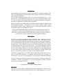
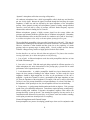
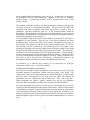
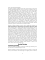
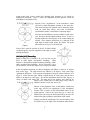
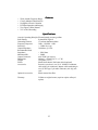
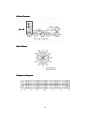
ROYER Labs
Model SF
Stereo Ribbon Velocity
Microphone
Operation Instructions Manual
& User Guide
Made in USA
TA BLE OF C ONTEN TS
Model SF
Stereo Ribbon Velocity Microphone
Table of Contents
page 1
Introduction
page 2
Description
page 2
Users Guide
page 2
Amplification Considerations
page 3
Recording Techniques:
-Conventional X-Y Recording
page 6
-Mid-Side (M-S) Recording
page 7
Applications
page 9
Care and Maintenance
page 11
A Little Bit of History
page 12
Features
page 13
Specifications
page 13
Wiring Diagram
page 14
Frequency Response and Polar Pattern
page 14
Warranty
page 15
1
Introduction
Congratulations on your purchase of a Royer Labs model SF-12 ribbon microphone. The
SF-12 is a handcrafted precision instrument capable of delivering superior sound quality
and overall high performance.
This operator’s manual describes the SF-12, its function and method of use. It also
describes the care and maintenance required to ensure proper operation and long service
life. The users guide section of this manual offers practical information that is designed to
maximize the performance capabilities of this microphone.
Royer Labs products are manufactured to the highest industrial standards using only the
finest materials obtainable. Your model SF-12 went though extensive quality control
checks before leaving the factory. Normal care, given to any quality instrument, is all that
is required to assure years of trouble-free service.
Please read the manual thoroughly in order to become familiar with all of the SF-12’s
capabilities. It will assist you in making the most of its superior acoustic properties.
This owner’s manual is a handy reference guide and we suggest you refer to it whenever
questions arise on the use and care of your SF-12 ribbon microphone.
Description
The SF-12 is a compact stereophonic ribbon microphone array consisting of two (2)
matched microphone elements that are placed one above the other. When held vertically,
connector down and the “ROYER” logo facing the sound source, the upper microphone is
the right channel and the lower one is the left channel, from the perspective of someone
behind the mic. The microphone elements are each bi-directional (figure-eight) and may
be addressed from either side with equal sensitivity. The in-phase signals are achieved
when the microphone is addressed from the front, as indicated by the “ROYER” logo. If,
however, the microphone is hung on its cable, the connections to the preamplifier should
be reversed since what was the left transducer is now responding to signals from the right
and vice versa from the perspective of someone at the microphone location.
Your SF-12 is equipped with a 5-pin XLR extension cable and an adapter that fans out to
twin 3-pin male XLR connectors. As shipped from the factory, the connectors are
marked “upper” and “lower” since calling them ‘”left” and “right” could lead to confusion.
The SF-12 is tolerant of shock and vibration, and is unaffected by changes in temperature
or humidity. Normal care appropriate to any precision instrument is all that is required
to assure years of trouble-free service.
User Guide
Using the SF Ribbon Microphone
Operation
The SF-12 is a versatile device capable of accurate sound reproduction. There are a few
important facts about ribbon microphones that are key in understanding how to use them
2
intelligently.
1. The SF-12 is a side-address, bi-directional microphone and the rejection in the “dead”
areas is very strong. Due to this directionality, ribbon microphones should be placed at
1.3 times the distance normally used with omni-directional microphones, or about the
same distance used for cardioid microphones. This method is used to achieve the same
ratio of direct to reflected sound.
2. In the horizontal plane, ribbon microphones do not discriminate against the “highs” off
axis, nor do they boost them on axis. Therefore, several instruments or vocalists can be
placed in front of the microphone without favoring the performer in the center of the
group.
Several performers can be grouped at both the front and the back of the microphone, with
one proviso; since the outputs are out of phase at the front and back of the microphone,
cancellation can result if two tenors are placed on opposite sides at equal distances and
are singing in unison. Therefore, listen to the feed before committing to it.
3. The Royer model SF-12 requires no power supply and is safe to use on consoles with
phantom microphone powering, provided that the cabling is done properly. It should be
noted that not all ribbon microphones are compatible with phantom-powering systems,
so check the manufacturer’s recommendations before using other ribbon microphones.
Faulty or improperly wired cables could also cause problems with your SF-12.
4. Never attempt to “test” the SF-12 or any ribbon microphone with an ohmmeter. A
blown ribbon could result.
5. Always provide adequate protection for your SF-12, or any ribbon microphone for
that matter. If the microphone is to remain set up on a stand when not in use, place a
“mic sock” over it until it is to be used. Do not carry the microphone around without
placing a “mic sock” over it. Failure to follow this common-sense practice may yield a
stretched ribbon and compromised performance!
Amplification Considerations
The performance of a ribbon microphone is directly affected by the choice of microphone
preamplifier it is paired with. With so many mic preamps on the market, how do you
select one that gives the best possible performance with a ribbon microphone?
Additionally, what kind of performance can we expect from the preamplifiers built into
our mixing desks? While most preamplifiers will handle ribbon microphones well in most
recording situations, some preamps that work perfectly well with condenser or dynamic
mics may prove to be poor performers with ribbons.
To begin with, we must understand the fundamental differences between ribbon
microphones and other popular types, namely condenser and moving coil dynamics. A
ribbon microphone is actually a dynamic microphone that uses a flat, extremely low mass
ribbon element, rather than a coil/diaphragm assembly. For this writing, any mention of
3
“dynamic” microphones will relate to moving coil dynamics.
All condenser microphones have a built in preamplifier called a head amp and therefore
put out a hefty signal. Because the signal is buffered through the head amp, the output
impedance is rather low and less affected by the input impedance of the microphone
preamp. Most dynamic (moving coil) microphones generate a healthy enough electrical
current to work well with a variety of preamps, and their limited frequency response
characteristics make mic loading less of a concern.
Ribbon microphones generate a highly accurate signal, but the average ribbon mic
generates approximately 20dB less gain than that of condenser microphones. Remember,
the ribbon transducer does not have the benefit of a condenser mic’s built in “head amp”,
so a ribbon microphone relies solely on the microphone preamp for all its gain!
The so called ideal preamplifier is the proverbial “straight wire with gain”. This may be
considered the technological ideal and does not include “coloration” as a desirable feature.
However, coloration is often desirable and has given rise to the popularity of certain
preamps and even preamp stages in mixing desks. Neve® preamps and the famous
Trident® A Range mixing console are highly praised for their classic sound.
So what should we use with our beloved ribbon microphones? The features that translate
into top performance for a ribbon microphone are the following:
1. Lots of gain! A ribbon microphone works best with preamplifiers that have at least
60-70 dB of maximum gain.
2. Low noise is a must! With this much gain being required for efficient operation of a
ribbon microphone, the noise characteristics of the preamp play a pivotal role in overall
performance of the captured acoustic event.
3. Load characteristics: A suitable preamplifier should have input characteristics that
impose the least amount of loading to the ribbon element. In other words, the input
impedance should be high enough that its effect on the performance of the mic is
negligible. A good rule of thumb is to have a preamplifier with input impedance at least
five times the impedance of the microphone. For example, if the mic is rated at 300 Ohms
(as Royer’s are), the preamp should have an input-impedance of at least 1500 Ohms. If
the impedance of the preamp is too low, the microphone will lose low end and body.
4. Transparency: A good preamp should sound natural with no edginess. Tube preamps
sound warm, yet wonderfully transparent. Transformer coupled preamps sound punchy.
When recording with condenser or dynamic microphones engineers often choose mic
preamps that help “warm up the mic”, but warming the signal up does not need to be a
consideration with ribbon mics because they are by nature warm and realistic sounding.
At this point personal taste should prevail over anything.
Stereo Microphones and Ground Loops
Some preamplifiers are prone to developing ground loops when used in conjunction with
4
stereo or multi channeled microphones, such as the SF-12. Ground loops can develop in
the preamplifier with any stereo microphone, regardless of the type (i.e. condenser,
dynamic, ribbon). A ground loop manifests itself as unwanted noise, buzz or hum
(usually 120 Hz).
The condition is brought on when the left and right transducer elements are plugged into
two inputs of a stereo or multi-channel preamplifier. The pair of three-pin male XLR
connectors of the stereo microphone cable usually shares Pin-1 as ground, so they are
grounded to each other through the cable set. If the grounding scheme within the
preamplifier is poorly designed, or the distances to internal ground are too great, a ground
loop develops. The problem may be more apparent with ribbon microphones because of
the high gain required for proper operation.
You can perform a simple test to check for this condition (preferably done with a pair of
headphones to avoid feedback). Plug one side of the stereo microphone into either
preamplifier input. Listen to the output of the preamp. All should be quiet except for
the mic signal. Now plug the second side into the next preamplifier input. If a noise or
buzz develops, you have a ground loop. The ground loop may be very slight or more
pronounced, depending on the preamp. Battery powered preamps usually do not exhibit
this problem, and neither do well designed, line operated mic preamps. The simple fix is
to disconnect one of the microphone’s two Pin-1 ground connections. A better method is
to make a small ground lifter out of a male-female XLR barrel adapter. Switchcraft makes
a very nice one and it takes less than five minutes to wire it up. Simply connect Pin-2 to
Pin-2, Pin-3 to Pin-3, and leave Pin-1 disconnected. Correcting the problem at the
preamplifier would be preferable, but is often more difficult and/or expensive.
In conclusion, try to find the best preamp you can afford that has good gain
characteristics and low noise. Coloration is optional.
Equalization and Ribbon Microphones
One of the great strengths of ribbon microphones is how well they take EQ. Even with
substantial amounts of equalization, ribbons retain their natural, “real” quality. For
example, when a lead vocal is being performed on a ribbon microphone, you can actually
boost the upper end frequencies to the point where the ribbon mic emulates the
performance curve of a condenser mic with excellent result. This is not to say that a
ribbon microphone can replace a quality condenser mic, but the EQ friendliness
inherent in ribbon microphones does allow for an enormous amount of flexibility.
The reason that ribbon mics take EQ so well is because of their inherent low self-noise
(less than 15 dB) and unusually smooth response characteristics. Dialing in high amounts
of equalization on condenser or dynamic microphones also means dialing in extra amounts
of the microphone’s distortion products and self noise; garbage that contributes to an
unnatural, unpleasant sound. Because distortion and self-noise are almost non-existent in
ribbon microphones, high levels of EQ can be used without adding harshness or excessive
noise.
5
Hum Noise and Mic Orientation
All dynamic microphones, including ribbons, utilize powerful magnets in their motor
assemblies and matching transformers, and are, to some degree, susceptible to picking up
stray alternating magnetic fields. Power transformers (such as those found in guitar
amplifiers) and alternating current motors are the most likely sources of radiated noise.
Building wiring and electrical utility transformers are other likely sources. A welldesigned microphone provides shielding to minimize the effects of stray magnetic
radiation. In some cases complete isolation is impossible and the result is usually hum or
buzz. Ribbon microphones can potentially manifest this condition to a greater degree
because of their higher gain requirements. With vintage ribbon microphones, that employ
large bulky magnet structures, the problem can be worse. Royer SF-1 and SF-12
microphones are designed to minimize the effects of unwanted radiation by integrating the
transducer barrel as part of the magnetic return circuit. With this design, the barrel
housing the transducer serves to complete the North-South magnetic return and
neutralizes the effects of outside magnetic radiation. The SF-1 mono and SF-12 stereo
ribbon microphones go one step further by incorporating toroid impedance matching
transformers, which have a natural ability to repel magnetic radiation.
Dynamic and ribbon microphones are passive devices, meaning they incorporate no
external or internal power supplies and have no head amplifier and therefore cannot
produce hum on their own. Unwanted noise (hum) can only come from an external
source. Fortunately, there is a simple procedure that can be used to identify the source of
the noise and eliminate it. Repositioning a dynamic and ribbon microphone is the
number-one way to get rid of unwanted noise. If hum is detected, it means that the
microphone is in the proximity of an alternating magnetic field. While listening (preferably
with headphones) to the mic, move it around. The mic will “find” the noise source quite
easily. If you are miking a guitar amplifier and suspect the amplifier’s power transformer
may be the source of unwanted noise, move the mic around the amp. You will probably
find that the noise is louder as you approach the amplifier’s power supply and quieter
when you move it away. Eliminating the noise can be fairly simple and requires finding
the “null” point of the noise. The “null” point is the position that places the
microphone’s magnetic components away from the lines of radiation. Simply rotating the
microphone slightly is many times all that is required to cancel out the noise. This is
similar to the procedure guitarists use to eliminate noise from single coil guitar pickups.
There will be a “magic position” where the noise disappears completely. Finding the
exact position that also provides acceptable acoustic placement of requires a little
practice, but the results are well worth the time.
Recording Techniques
Conventional (XY) Recording
Orientation of the SF-12 microphone is such that the “ROYER” logo should always face
the sound source to avoid inadvertent phase reversals.
When the microphone is aimed as described, the center stage is picked up equally (3dB
down) by both transducers. Their included angle of 90 degrees produces a continuous
6
sound curtain with sources outside this included angle appearing to be outside of
loudspeaker placement. Figure 1 shows the alignment of polar patterns when the
microphone is oriented this way.
Because of the “togetherness” of the transducers, sound
will arrive at both microphone elements at the same time.
This means that the two channels can be summed to mono
with no comb filter effects, and room reverberation
(undesirable in mono) is cancelled to a surprising degree.
Since arrival time differences are not available as aural stereo
cues, how does this microphone produce stereo? It does so
through variations in the intensity of the sound striking the
ribbons. These intensity differences are a function of the
right angle at which sound strikes the ribbon. The polar
pattern shown in Figure 2 will clarify this.
None of this would be possible if the SF-12 didn’t exhibit
excellent frequency response regardless of the angle of sound
striking the ribbons.
Midside (MS) Recording
Based on what you’ve learned so far, you can now use the
SF-12 to make superb stereophonic recordings. What
follows is a description of another recording technique, which
adds a great deal more flexibility. All we can do here is give
you an intuitive feel for this subject, but it can get you started.
In the microphone placement we showed originally each ribbon is aimed at 45 degrees
from center stage. The angle between the ribbons is 90 degrees, with center stage
“splitting the difference”. Now rotate the microphone 45 degrees counter-clockwise as in
Figure 3. Notice that the upper ribbon is aimed directly at center stage, and the lower
ribbon is 90 degrees to center stage. We call the microphone aimed at center stage by a
variety of names; mid, mono, (M). The other unit in our package, now aimed at 90
degrees to the sound source at center stage can be called a
number of names as well; side, stereo, (S).
Because of the alignment of the S microphone, sound from
center stage will not be reproduced by this microphone
element. This is because of the bi-directional nature of the
pickup pattern. Some of the sound may try to move the
ribbon to the left, but just as much sound will try to move the
ribbon to the right, resulting in cancellation of the sound.
Figure 3
Imagine now that the sound source has moved around so that
it is all the way to the right of the microphone rather than in
7
front of it as before. Now the S microphone will respond to the source, but the M
microphone will not.
If the sound source moves to the left of the microphone, again the S microphone will
respond but the M unit will be silent. The important fact to note is that the output of the
S microphone will be 180 degrees out of phase to what it was when the source was at the
right. Please keep this in mind, because it’s crucial.
Examine the block diagram of Figure 4a. Note that the outputs of the two microphone
transducers fan out to four separate mixer inputs. For our purposes we will assume that
the top transducer of the SF-12 is the M microphone. Its preamplifier is so wired as to
feed equal signals to both “L” and “R” output busses. Note that if nothing else is
connected, the signal from this preamplifier will produce a monophonic, center channel
signal.
Figure 4a
Notice that the preamplifier associated with the S element feeds two more inputs of your
mixer, but that the phase has been reversed at position 4. The in-phase signal is assigned
to the “left” channel and the reversed phase signal feeds the “right” channel. If only the S
microphone is connected a monophonic signal results, but it will not be centered because
the two channels are not properly phased.
If your preamplifier lacks the ability to invert phase here is a
handy circuit to build an invert phase adapter. The adapter
can be built into a Male/Female Switchcraft barrel, or use a
piece of cable and 2 connectors
—1 male and 1 female.
For a start, set up your system so that the signal from the S setup will produce the same
signal level as the M signal, given the same level with respect to the two transducers.
Suppose we again move our sound source in such a way that it is right in front of the M
microphone. We hear a monophonic signal. No signal is produced by the S microphone
8
for reasons already stated. Now we move the sound source to the “left”. The signal falls
off somewhat as heard by the M microphone, but picks up at the S microphone. Because
of the electrical phase of this signal, it adds to the M signal feeding the “left” channel,
making the sound appear to be coming from the left. Signal also feeds the “right” channel,
but out of phase with respect to the M signal that also feeds the “right” channel. Thus,
while the “left” channel experiences an increase in output, the “right” channel loses signal
and this adds to the feeling that the sound source is truly at the “left.”
Now we move the sound source to the “right” of the SF-12. As before, signal reaching the
M microphone decreases in level, while the signal at the S microphone increases.
Remember, we are talking about a bi-directional ribbon. The phase of the sound source at
the S microphone is opposite to what it had been when the source was located at the
“left” of the microphone.
The combination of the reversed phase from the microphone and the inverted phase
feeding the “right” channel means that the signal is now in phase with the “right” portion
of the M signal. It is, however, out of phase with respect to the M signal feeding the
“left” output channel. With the increased output on the “right” channel, coupled with the
decreased output on the “left” channel, our sound source appears to be on the “right”
channel, just as it is supposed to be.
If we remove the S signal, we have pure monophonic sound. As we add more S signal,
stereo appears. If we make the level of the S signal equal to that of the M signal, we will
recreate the sound stage. If we add more S than M, we make the stage wider than life.
That might come in handy if stereo was insufficient in the live situation. If the recording
had been conventional, little could to be done to improve matters.
It is often helpful to make a recording with the M signal fed into the recorder left channel
and the S signal on the right channel. Later, in the calmer light of the control room, you
can connect the recorder’s outputs as you did the microphone elements in our discussion.
Not only can you determine the nature of the reproduced soundfield but you can treat the
S signal in other ways. For instance, suppose you have a disk-recording situation in
which the vertical information is such that groove lifts tend to occur. You can take the S
signal, limit it, equalize it and feed it to your mixer as described. Almost magically, the
vertical problems have vanished and the stereo effect is still excellent.
Space does not permit a fuller discussion of the M-S intensity stereo format, first
described by Alan D. Blumlein over 50 years ago. We suggest the following reading on the
subject:
W. Dooley & R. Streicher
“M-S Stereo: A Powerful Technique for working in Stereo”
J. Audio Eng. Soc., Vol. 30 pp.707 (1982 Oct.)
Applications
The SF-12 combines high quality audio performance with unbeatable stereo separation
and imaging. The microphone is housed in a trim package, free of the cluttered look
9
produced by switches and adjustments. Its small size and matte black chrome finish
create a minimum disturbance of the visual field, especially important where the
microphone must not obstruct the view of an audience or of a motion picture or TV
camera.
The SF-12 is easy to use, robust and reliable. Neither temperature nor humidity affects it.
SF-12 has numerous applications. Along with its useful-ness as an overhead drum mic, a
stereo acoustic piano or guitar mic, and organ recording, it can be applied to motion
pictures because of its natural stereo capabilities. It is also very useful for recording
ensembles such as big bands, orchestras and jazz groups.
Because of the coincident crossed figure-8 pattern of this product, it is eminently suitable
for M-S (mid-side) recording. Once a recording has been completed using the proper
orientation, the soundfield can be adjusted from pure monophonic on one hand to “super
wide” stereo on the other.
Although spaced microphones can produce some of these results, such recordings can
suffer from “comb filter” effects -peaks and dips in the frequency response as the
soundfield is adjusted. When the SF-12 is used, however, only the feeling of space
changes. The sonic quality does not. More detailed information on M-S techniques is
presented in the literature supplied with the SF-12, or in manuals accompanying
commercial M-S equipment.
While the SF-12 yields excellent results in the recording or broadcasting of material “on a
grand scale”, its suitability for the recording studio is astounding. To prove the point,
here are three typical examples:
1. Object: to record a vocal with acoustic guitar. Two separate mono
tracks are required with little leakage between the tracks. One stand
and one SF-12 can do the job of two, when the two axes of sensitivity
are correctly oriented.
2. Object: to record a drum kit. The wide
bandwidth and superb frequency response of
the SF-12 capture every percussive nuance, and
a touch of EQ can be used, if necessary, to bring out various
elements. Experience has shown that an additional microphone on
the kick drum is often all that is required. Meanwhile, the “dead”
axes can reduce leakage from unwanted sound sources.
3. Object: to record strings accurately. String overdubs fare well
when the SF-12 is used, because of its “wall-to-wall” stereo imaging and uniform, smooth
frequency response.
10
This microphone does not suffer from overload because
there are no integral electronics. Therefore, the available
dynamic range is determined solely by the
characteristics of the preamplifier with which it is used.
In summary, the SF-12 is truly a microphone for all
seasons and is a refreshing change from the philosophy
of “dedicated” mics geared to specific instruments or voices.
Care and Maintenance
The SF-12 is a well-built precision instrument. All that is required to ensure proper
operation of this microphone is to follow some common-sense rules.
1. To avoid transducer damage, do not expose the microphone to severe shock or
vibration. If the microphone is accidentally dropped, test the microphone to see if
damage has occurred before returning it to service.
2. Do not expose the microphone to direct blasts of air. Use a windscreen or suitable
blast filter when close miking a vocalist or certain types of wind instruments. Ppopping does not necessarily damage the ribbon element but may produce
unacceptable preamplifier overload and could cause damage to speaker systems.
3. Do not expose microphone to liquids or caustic smoke.
4. Do not expose the microphone to strong alternating electromagnetic fields, i.e. the
power transformers in amps, or a hum may result.
5. Use a soft cloth to clean the microphone body. A small amount of denatured alcohol
can be used to remove fingerprints and other stains.
6. Keep metal filings away from the microphone at all times.
7. When not in use, store the microphone in its protective wooden case, or covered with
a “mic sock”.
8. Leave disassembly of the microphone to a trained technician. There are no userserviceable parts inside.
11
CAU TION!
Keep recorded tapes springwound watches and personal credit cards using
magnetic coding away from the microphone to prevent possible damage caused
by the transducer’s magnets
A L i t t le Bi t o f H i st o r y
The ribbon-velocity microphone design first gained popularity in the early 1930s and
remained the industry standard for many years. Their characteristic sound signature can
still be appreciated today in recordings of the 30s, 40s, 50s and early 60s.
Ribbon microphone development reached its pinnacle during this time. Though they were
popular with announcers, one of the disadvantages of ribbon microphones was their
immense size. Even though these devices were considered state-of-the-art, magnetic
structures of the time were bulky and inefficient. Transformers suffered a similar
deficiency. When television gained popularity in the late 1940s, it was obvious that their
size was intrusive and objectionable. They were difficult to maneuver and broadcasters
soon looked for a suitable replacement. Even though these microphones performed very
well, their days were numbered. Newer dynamic and condenser mics would soon replace
them. The new designs were compact, rugged and sensitive. It wasn’t long before the
television industry embraced these new designs. Radio followed the trend shortly
afterward. Further technological development of ribbon microphones was considered
unnecessary and the beloved ribbon soon faded into obscurity. It is a fate reminiscent of
that of the vacuum tube when transistors hit the scene.
Some of their unique characteristics, unmatched even by today’s modern condensers and
dynamics, are still revered by many professionals, as evidenced by the high prices that
vintage ribbons command in the marketplace.
Traditional-style ribbon microphones are still being manufactured in limited quantities
today by a few companies. These microphones are essentially similar to the designs of
the 1930s and limited to specialized applications.
Recent developments in magnetics, electronics and mechanical construction procedures
have made it possible to bring the ribbon microphone back to the forefront of the audio
field. This is similar to the resurgence vacuum tubes have made in recent years, now that
technology has enabled further development of the state of the art in numerous areas. A
renewed interest in these designs (both tube technology and ribbon microphones) is
driven by the unique characteristics these devices posses, which remain unmatched even
by some of today’s marvels.
Today’s ribbon microphones can be made smaller, and have sensitivity levels matching
those of modern dynamic microphones. Aside from the superlative audio qualities of
these microphones, their smooth frequency response and phase linearity make them
ideally suited for the new digital formats that dominate the industry today.
12
Features
•
•
•
•
•
•
Wide, Smooth Frequency Range
Closely Matched Characteristics
Negligible Off-Axis Coloration
Excellent Separation and Imaging
True Figure-8 Polar Patterns
X-Y or M-S Recording
Specifications
Acoustic Operating Principle:Electrodynamic pressure gradient
Polar Pattern:
Symmetrical Figure-8
Generating Element:
1.8 micron aluminum ribbon
Frequency Response:
30Hz - 15000Hz ±3dB
Sensitivity:
> -52dBv Re.1v/pa
Output Impedance:
300 Ohms @ 1 kHz
Recommended Load
Impedance:
> 1500 Ohms
Maximum SPL:
> 130dB
Output Connector:
male XLR 5 pin (stereo)
Dimensions:
206mm L x 25mm W (8” L x 1” W)
Weight:
369 grams (13 oz.)
Finish:
Matte black chrome, Dull satin nickel (optional)
Accessories:
Protective wood case, one (1) 18’ shielded 5-conductor
cable with 5-pin connectors, adaptor cable terminating in
two (2) XLR type 3-pin male connectors, mic clip, mic
sock
Optional Accessories:
Shock mount, blast filter
Warranty:
Lifetime to original owner (repair or replace at Royer’s
option)
13
W i r i n g D i ag ram
Polar Pattern
Frequency Response
14
Warranty
Royer Labs warrants its products to be free from defects in materials or imperfect
workmanship. This warranty is offered to the original owner without time limit. Royer
Labs will repair or replace any product that fails to meet published specifications during
the warranty period. This warranty does not apply if the product has been damaged by
accident or misuse, or as a result of repair or modification by other than a Royer Labs
customer service facility authorized to service this product. To validate this warranty, the
registration card and a photocopy of the sales receipt from an authorized Royer Labs
dealer must be on file with Royer Labs. Should it ever become necessary to service your
Royer Labs product, please contact the factory. In our continuing effort to improve our
products, Royer Labs reserves the right to make improvements without notice or
obligation. Specifications and prices are subject to change without notice or obligation.
Serial Number_____________________________
Upper Sensitivity________Resonance__________
Lower Sensitivity________Resonance__________
Date of Purchase___________________________
ROYER Labs
N Ford Street
Burbank CA Telephone: Fax: wwwroyerlabscom
15