1
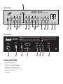
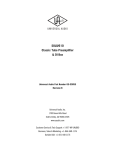
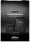
JCM 2000
DSL201 & DSL401
Combos
Marshall Amplification plc
Denbigh Road, Bletchley, Milton Keynes, MK1 1DQ, England
Tel: (01908) 375411
Fax: (01908) 376118
Web Site - http://www.marshallamps.com
Whilst the information contained herein is correct at the time of publication,
due to our policy of constant improvement and development, Marshall
Amplification plc reserve the right to alter specifications without prior notice.
Nov ‘98
Handbook
1
WARNING! - Important safety instructions
A.
B.
C.
D.
E.
ALWAYS fit a good quality mains plug conforming to the latest B.S.I. standards where necessary (UK only).
NEVER attempt to by-pass the fuses or fit ones of the incorrect value.
NEVER attempt to replace fuses or valves with the amplifier connected to the mains.
DO NOT attempt to remove the amplifier chassis, there are no user serviceable parts.
Refer all servicing to qualified service personnel. Servicing is required when the apparatus has been
damaged in any way, such as the power supply cord or plug is damaged, liquid has been spilled or objects
have fallen into the apparatus, the apparatus has been exposed to rain or moisture, does not operate normally
or has been dropped.
F. NEVER use an amplifier in damp or wet conditions.
G. ALWAYS unplug this apparatus during lightning storms or when unused for long periods of time.
H. Protect the power cord from being walked on or pinched particularly at plugs, convenience receptacles and at
the point where they exit from the apparatus.
I. DO NOT switch the amplifier on without the loudspeaker connected.
J. ENSURE that any extension cabinets used are of the correct impedance.
K. PLEASE read this instruction manual carefully before switching on.
Follow all instructions and heed all warnings.
WARNING : This apparatus must be earthed!
WARNING : Do not obstruct ventilation grille and always ensure free movement of air around the amplifier!
USA ONLY - DO NOT defeat the purpose of the polarised or grounding type plug. A polarised plug has two
blades with one wider than the other. A grounding type plug has two blades and a third grounding prong.
The wide blade or the third prong are provided for your safety. When the provided plug does not fit into your
outlet, consult an electrician for replacement of the obsolete outlet.
KEEP THESE INSTRUCTIONS
Introduction
With the introduction of the Marshall JCM2000 range of DSL50 and 100 heads, the
TSL100 head and the TSL122 combo, the quintessential definition of ultimate tone
and usable features has been rewritten. This quartet of great amps has now spawned
a new generation of compact, lower power combo amps, the DSL201 and DSL401,
destined to be classics for both studio and session/club gigs.
As the names imply these amps are 20 Watts and 40 Watts respectively, but as these
are true valve amps, built to exacting standards, do not let the lower power ratings
lull you into thinking that they are mere practice amps, as nothing could be further
from the truth! The benefits of using a lower powered amp are many fold, not least
that of being able to push the output valves harder for extra warmth at manageable
volume levels. Just remember how many famous artists have used smaller amps to
record those classic tracks and how many use lower powered amps on stage, to help
balance the sound. Worried that your amp is great for the studio and small club, but
not for bigger gigs? Well don’t, there are ways of making them sound much bigger
than they really are. Just adding a Marshall 1960 4x12” is going to increase the
spread and SPL of your sound, by simple physics. If not mic or D.I. through the PA.
The onboard D.I. output of your DSL201 or 401 contains Marshalls acclaimed speaker
emulation circuit, making accurate sounding D.I.ing as simple as plugging in a cable!
Silent recording in your project studio? Again, use the speaker emulated D.I. output,
only this time turn down the ‘output master’ volume control (which by the way,
controls the apparent output power) to zero and still capture the full valve tone of
your amp on tape (or disc!)
2
Continuing with the features of your amp, both the DSL201 and 401 have two
totally independent, footswitchable channels, notably ‘Clean’ and ‘Overdrive’ which
cover the whole range of tones from sparkly clean, through classic and modern
‘Crunch’, through to super-saturated Lead Overdrive.
On top of this, the DSL401 offers a three channel option by having the ability to
(foot)switch between OD1 and OD2 - OD2 having even more gain than OD1 - in fact
a staggering 20dB more! Thus giving the ability to switch from great clean to
crunch and then to lead. Remember, the Clean channel not only does clean, it
crunches up in a great traditional way too, just turn it up and drop the apparent
output power (output master) down to a socially acceptable level.
Rounding out the features, your DSL201 or 401 also has a parallel FX loop with a
mix control and large spring ‘Sound Enhancements’ reverb, with footswitch facility
(DSL401 only).
It is important to mention here that your DSL201 or DSL401 use EL84 output
valves, as opposed to either the 5881/6L6 or EL34 valves used in bigger Marshall
amps. The EL84 is the classic output valve for smaller British style amps (and some
U.S. ones too) and is a great valve to achieve superb tone at lower power levels.
Normally they are used in a very simple circuit that features no negative feedback
and are run in the cathode biased mode which gets close to them being run in class
A, which makes for a very squashy compressed tone, as typified in the VOX AC30
for instance. Whilst this mode is great for these classic amps, we felt that this
simple operating mode limited the amount of versatility required from an amp as
diverse as the DSL201 & 401, in this modern age. Therefore, after careful study of
how these classic amps worked and how the bigger Marshall’s worked, a fresh
design that covers a broader spectrum of tones has been incorporated into the
DSL201 and 401. We feel that it does it with great style.
DSL201 & DSL401 Front Panel Features (pages 32 & 34)
Please note both models DSL201 and DSL401
are described together, any model variations are
indicated.
guitar you use. For instance, a guitar with
humbucker type pick-ups is not going to sound
as open and clean as one with single coil type
pick-ups, yet will provide that great mid range
bark that we are accustomed to for rock playing.
✪ User Hint - where you see text starting with
this sign, we have described some slight
technical paraphenalia in order for you to
understand what is going on inside your amp and
we hope will help you in creating the tone that is
best for you and your amp.
2. Clean Gain
This controls the preamp level of the clean
channel, at lower settings the sound will be very
clean and at higher settings the sound will start
to ‘Crunch’ up in a traditional blues sort of way.
In between, around midway, depending on what
type of guitar you are using, you will find some
great semi-clean/semi-crunch tones, just like
those great vintage amps that had minimal
features, but great tone.
1. Input Jack
As most manuals state, plug your guitar in here.
✪ User Hint - Amusement aside, it is
worthwhile remembering that you should use a
high quality guitar lead to achieve optimum
performance. If you are unsure what constitutes
a high quality lead then most good music stores
should be able to give you good advice, but
remember, it may not be the cheapest one going!
✪ User Hint - there is a capacitor across the
gain control that brightens up the tone when set
to lower levels. This helps to ‘cut’ through at
low volumes and adds ‘twang’ to the tone. As
you bring up the gain control the effect of this
decreases and the tone becomes fatter. If you
It is also worth pointing out here that how an
amp sounds is VERY dependent on the type of
3
5. Overdrive Gain
find the tone too thin with the gain control down
either take some of the high end off with the
treble control, or alternatively, bring the clean
gain control up until you achieve the depth of
tone you want and then control the volume of
the amp with the ‘master volume’ control.
This controls the amount of gain drive available
for the overdrive channel, from mildly almost
clean crunch to super-saturated overdrive,
depending where this control is set, i.e. lower is
less and higher is more. Wherever this control is
set is going to give you a wide palette of tones to
work with, depending on the type of guitar, EQ
settings, how hard you push the power amp, etc.
3. Clean Treble, Mid, Bass
These controls vary the E.Q. and voicing of the
Clean channel.
Note: the difference between OD1 and OD2
(DSL401 only) is approx 20dB more gain on
OD2. The DSL201 is preset to the gain levels of
OD2 and does not have the OD1 facility.
✪ User Hint - These controls are early on in the
amplifier chain and as such not only control the
tone of the Clean channel, but also how the clean
channel reacts ‘gain’ wise. For instance, if the
mid control is advanced (especially with higher
gain control settings) the sound will become
more ‘singing’ in a blues/traditional rock kind of
way. But if the mid control is backed off
towards (or even) zero the gain emphasis is
placed on the treble and bass controls and gives
more to work on, especially on cleaner, lower
gain settings, as would be the case for country,
jazz, or good old chord strumming.
✪ User Hint - Due to the immense amount of
gain and saturation available on the preamp of
the DSL401, particularly when using high output
humbucker pick-ups, the 20dB difference
between OD1 and OD2 may become less
apparent. In this case, back off the settings of
the gain control slightly until the difference
becomes more useable again.
✪ User Hint - One of the beauties of using a
lower power amp is that it makes the power amp
distortion more easy to use and by lowering the
input gain control and bringing up the channel
volume control will give you a whole new load
of tones to play with, as well as making the amp
run quieter, especially if you use the ability of
the ‘master volume’ to emulate a lower powered
amp.
A good starting point is to set these three
controls to their ‘midway’ position and by
experimenting with the ‘feel’ of how they
interact with the amp, build up a wide palette of
tones for future use.
4. Channel Switching
The channels of your DSL201 or DSL401 can
either be switched from the front panel, or via an
external footswitch - connection of the
footswitch is described later.
6. Overdrive Volume
This control adjusts the level of sound coming
out of the overdrive preamp channel and allows
you to balance it against the Clean channel.
DSL201 - The front panel switching
arrangement consists of two LEDs and a single
pushswitch, to switch between either the clean
(Green LED) or Overdrive channels (Red LED).
Switch out is Clean, switch in is Overdrive.
✪ User Hint - To achieve the normal Marshall
style heavy rock ‘punch & crunch’ especially at
lower volume levels, this control should be used
to keep the volume down and the output Master
Volume should be kept higher. To achieve a
squashier type tone, great for lead work, then use
this control higher and bring the level down on
the output Master Volume.
DSL401 - Here the front panel switching
arrangement consists of three LEDs (Green =
Clean, Yellow = OD1, Red = OD2) and two
pushswitches, marked CLN/OD and OD1/OD2.
To select Clean the switch marked CLN/OD
must be released to its out position (Green LED
will be on). To select either OD1 or OD2, push
the CLN/OD switch in and select either OD1 or
OD2 by pushing or releasing the switch marked
OD1/OD2 and the appropriate Yellow or Red
LED will illuminate. To revert back to Clean,
release the CLN/OD switch once more. Do not
worry, you do not have to go through OD1 to
reach OD2, these channels can be pre-selected.
✪ User Hint - When using the less gain/more
level way of driving the power stage, keep the
overdrive gain low and use this volume control
to drive the power amp.
7. Overdrive Treble, Middle, Bass
As opposed to the ‘Clean’ channel, these
controls are placed after the distortion generating
circuitry of your amp and as such affect the
texture of the tone, rather than the gain of the
channel, especially when using high levels of
preamp gain.
✪ User Hint - These functions are repeated on
the footswitch. Remember that plugging the
footswitch into the amp will override the front
panel pushswitches.
✪ User Hint - Although many textures are
available from this relatively simple
configuration, a good starting point (again) is to
set everything midway. For a more modern
4
✪ User Hint - As the (rear panel mounted)
speaker emulated D.I. output is derived from this
circuit you can balance the sound coming out of
the loudspeaker from zero to full, whilst
maintaining a constant level out of the D.I.
output and enjoy the tonal qualities of a pushpull valve output stage - ideal for silent
recording, direct to the desk.
heavy’ tone, turn the mid control down and
boost the treble and bass. For a more classic
‘rock’ tone bring back the mids and bring the
treble and bass down a bit.
✪ User Hint - When using the less gain / more
volume approach, the tone controls can be used
to help ‘push’ the power amp for a more refined
tone.
11. Standby Switch
8. Master FX Mix
This turns the high voltage feed to operate the
valves on and off.
This controls the balance of the return from the
parallel FX loop (see rear panel details for
connection) with the amps direct signal.
✪ User Hint - This switch should be used for
(a) allowing the amp to warm up before turning
the Standby on (at least a minute - preferably 2/3
minutes if possible) and (b) turn the Standby
switch off when taking a break (rather than
turning off the whole amp), thereby keeping
your amp at the ‘ready’, without waiting for it to
warm up again. Remember to do these two
simple rules and your valves will love you for it
and should last an awful lot longer before
replacement is needed.
✪ User Hint - As the FX loop is of the parallel
kind, this is where you should use time delay
effects (i.e. echo, reverb, pitch shifting, chorus,
etc.). For optimum use the direct signal in your
processor should be turned to zero so that only
the effect signal is returned to the amp, this way
the tone integrity of the direct amp signal is
unimpaired.
9. Master Reverb
12. Power Switch
This controls the level of the internal spring
reverb circuitry from a slight shimmer to a
cavernous depth. DSL401 only - the reverb has
the facility of being footswitchable via the rear
panel socket and optional PEDL-10013
footswitch.
This turns the mains electricity that feeds your
amp on and off. As stated before, turn this
switch on for at least a minute or two before
turning the Standby on, to allow your amp to
warm up.
10. Master Volume
✪ User Hint - For environmental reasons at
least, if leaving your amp for more than a normal
gig type break or so, turn your amp off at this
switch, it will save electricity. Also, if leaving
your amp unused for a long time, always
remember to disconnect your amp’s power cord
from the mains supply, at the very least it will
prevent someone else accidentily turning it on
without realising.
Apart from the obvious function of being the
master level control for the whole amp
(regulating the output volume of both the clean
and the overdrive channels), this control actually
affects the apparent power level of the power
amp section itself. This means that, at lower
settings, the amp acts and feels like an even
lower powered amp, along with the kind of
smooth saturation that you get from pushing a
power amp into distortion.
DSL201 & DSL401 Rear Panel Features (pages 32 & 34)
1. Channel Footswitch Jack
3. FX Loop Send Jack
This socket takes the jack connected to the lead
of the channel change footswitch
(CLEAN/OVERDRIVE - DSL201, CLN/OD &
OD1/OD2 - DSL401).
Connects the DSL amp to the input of the
external FX processor.
4. FX Loop Return Jack
Connects the output of the external FX processor
back into the DSL amp circuit.
2. Reverb Footswitch -(DSL401 only)
Takes the optional footswitch (PEDL-10013) to
remotely control the reverb function.
5. Speaker Emulated D.I. Out Jack
Line level, emulated output signal for
connection into PA or recording Mixing Desks
etc.
5
6. Loudspeaker Output Select (DSL401 Only)
The DSL201 is fitted with a single loudspeaker
socket preset at an impedance of 16 ohms, which
is normally plugged into the internal 16 ohm 12”
loudspeaker. To use an external loudspeaker,
just unplug the internal speaker and plug into
your external cabinet (this must be 16 ohms
only), for instance, a Marshall 1960 4x12”.
This switch selects the output impedance of the
amplifier for either 8 or 16 ohm use, to match to
alternate speaker systems. Although more on
this will be covered later, it is important to
remember that the internal loudspeaker is 16
ohms and that the amp must be set to match that
(16 ohms).
The DSL401 is fitted with two parallel wired
loudspeaker jack sockets and a selector to switch
between the normal 16 ohms (to suit the internal
speaker) or 8 ohms. This makes the choice of
extension cabinets even wider. For instance, not
only could you use a Marshall 1960 4x12” cab,
with or without the internal speaker (set amp to
8 ohms if using both, keep on 16 ohms if using
without internal speaker), but you could also
make the choice of various Marshall 1x12” or
2x12” extension cabs. But always make sure
that the output selector is set correctly !
7. Loudspeaker Output Jacks
One (1) only on DSL201, two (2) on DSL401.
These are identified by having RED jack socket
nuts and connect the amplifier output to either
the internal (or an external) loudspeaker system.
WARNING! At no time must the amplifier be
allowed to run with no loudspeaker (or
appropriate loudspeaker type load) connected to
its output. Otherwise serious and expensive
damage may occur.
i.e.
1 x 16 ohm speaker = 16 ohm output
8. H.T. Fuse - See specifications for
correct value
2 x 16 ohm speaker = 8 ohm output
This fuse protects your amp in the case of a fault
occurring with any of the high voltage circuit of
your amp. The usual reason for this to blow is
when an output valve has become faulty.
1 x 8 ohm speaker = 8 ohm output
WARNING! Never operate your DSL valve
amp without a loudspeaker, or suitable
loudspeaker type load, connected to the output,
even when using the output Master Volume set
to zero for silent recording. Otherwise
expensive damage may occur!
9. Mains Input
Use the supplied power cord to connect your
amp to the mains supply.
USING EFFECTS SYSTEMS
10. Mains Fuse - See specifications
for correct value
Your DSL combo amp is fitted with parallel FX
Loop, this is placed after the gain and distortion
parts of the preamp and is the ideal place for
inserting time varying effects, such as delay,
digital reverb, chorus, pitch shifting, etc. By
being a parallel loop, this means that the direct
signal is kept within the DSL’s circuit and
therefore your tone is not degraded by sending it
outside the amp. To use the loop connect your
effects processor (rack type units are better at
this job) as described earlier, turn the effects
units direct signal path off (the FX units manual
will tell you how to do this), set up the unit to
give you the effect you require and then balance
your direct sound and effected sound using the
FX MIX control on the front of your amp. Easy!
This fuse provides overall safety protection in
the case of your amplifier developing a major
electrical fault.
✪ User Hint - The fuses fitted to your amp are
there to provide you with safety protection in the
case of a fault developing. If they blow it means
something is wrong, usually a valve is getting
old, but under no circumstances fit a fuse of a
different value to stop it from blowing, as this
could be very expensive in terms of safety and
cost. Remember, if a fuse blows, it has blown
for a reason.
LOUDSPEAKER SYSTEMS
Floor type effects stomp boxes are designed to
work in between a guitar and the input of an amp
and should not be used in a parallel loop,
otherwise some very weird and undesired effects
could occur. For their best use, use them where
they are designed to go.
The DSL201 and DSL401 combo amps are each
fitted with a Marshall designed 12” loudspeaker,
each one developed to work with your amp to
produce the great tone that you expect from a
Marshall amp. The 1x12” format makes for a
very highly portable package that works great in
most circumstances. However, if you require a
bigger sound, or just a different one, there are
numerous cabinets manufactured by Marshall
that will interface with your DSL combo, with
ultimate ease.
6
4
DSL201 Front Panel
CLN/OD
TREBLE
4
6
GAIN
4
6
2
8 2
0
10
INPUT
1
MIDDLE
4
6
8 2
0
10
BASS
4
GAIN
6
8 2
0
JCM 2000 - DSL 201
10
4
8
0
2
10
VOLUME
4
6
6
8 2
0
10
8 2
0
10
CLEAN
2
TREBLE
4
6
MIDDLE
4
6
8 2
0
10
BASS
4
0
10
FX MIX
4
6
6
8 2
8
0
D U A L S U P ER L EA D
REVERB
4
6
2
10
8 2
0
10
3
5
6
10
8
0
8
9
ON
ON
STANDBY
POWER
11
12
10
MASTER
7
OFF
VOLUME
4
6
8 2
0
OVERDRIVE
OFF
10
DSL201 Rear Panel
CAUTION!:
Made in England by:
Marshall Amplification plc,
Bletchley, Milton Keynes, England.
MAINS INPUT
120V ~ 60 Hz
100 Watts
MAINS FUSE
(T1A - 230V)
(T2A - 120V)
TO REDUCE THE RISK OF FIRE REPLACE FUSES WITH THE SAME TYPE AND RATING ONLY. DISCONNECT SUPPLY CORD BEFORE
CHANGING FUSE. TO REDUCE THE RISK OF ELECTRIC SHOCK DO NOT REMOVE COVER. NO USER SERVICEABLE PARTS INSIDE. REFER SERVICING TO
QUALIFIED SERVICE PERSONNEL.
(T250mA)
LOUDSPEAKER OUTPUT
20W into 16 Ω
SPEAKER EMULATED
D.I. OUT
9
8
DSL201 SPECIFICATIONS
Power Output - 20 Watts RMS into 16 ohms
Valve complement - 4 x ECC83/12AX7 and 2 x EL84
Loudspeaker Type - 12” 16 ohm 50 Watt Model SPKR-00072
Mains Requirement - Preset for 117V~60Hz or 230V~50Hz
Other variations to special order - see local distributor for information.
Mains Fuse - T2A - 117V or T1A - 230V
H.T. Fuse - T250mA
7
5
SHOCK HAZARD. DO NOT OPEN. TO REDUCE THE RISK OF FIRE OR ELECTRIC SHOCK
DO NOT EXPOSE THIS EQUIPMENT TO RAIN OR MOISTURE. THIS APPARATUS MUST BE EARTHED.
RISQUE DE CHOC ELECTRIQUE. NE PAS OUVRIR. POUR EVITER LES RISQUES D’INCENDIE ET
DE DECHARGES ELECTRIQUES, N’EXPOSEZ JAMAIS CET APPAREIL A L’HUMIDITE OU A LA PLUIE.
CONNECTER CET APPAREIL A LA TERRE.
POUR EVITER LES RISQUES D’INCENDIE UTILISER UN FUSIBLE DE MEME TYPE ET DE MEME CALIBRE. DEBRANCHER AVANT DE
REMPLACER LE FUSIBLE. POUR EVITER LES RISQUES DE DECHARGES ELECTRIQUES, NE PAS OUVRIR LE COUVERCLE. CET APPAREIL NE COMPORTE
AUCUNE PIECE SUSCEPTIBLE D’ETRE REPAREE PAR VOS SOINS. FAITES TOUJOURS APPEL A UN TECHNICIEN QUALIFIE POUR TOUTE REPARATION.
HT FUSE
WARNING!:
AVIS!:
ATTENTION!:
WARNING!: RISK OF HAZARDOUS ENERGY!
AVIS!: ENERGIE ELECTRIQUE DANGEREUSE!
10
!
FX LOOP
CHANNEL
FOOTSWITCH
RETURN
SEND
4
3
1
4
DSL401 Front Panel
CLN/OD
CLEAN
TREBLE
4
6
GAIN
4
6
2
8 2
0
10
INPUT
1
MIDDLE
4
6
8 2
0
0
10
GAIN
6
4
8
0
JCM 2000 - DSL 401
OD2
BASS
4
8 2
10
OD1/OD2
OD1
2
10
VOLUME
4
6
6
8 2
0
10
MIDDLE
4
6
8 2
0
10
CLEAN
2
TREBLE
4
6
8 2
0
10
BASS
4
0
FX MIX
4
6
6
8 2
8
10
0
D U A L S U P ER L EA D
2
10
REVERB
4
6
8 2
0
10
3
5
10
8
0
7
8
9
ON
ON
STANDBY
POWER
11
12
10
MASTER
6
OFF
VOLUME
4
6
8 2
0
OVERDRIVE
OFF
10
DSL401 Rear Panel
CAUTION!:
Made in England by:
Marshall Amplification plc,
Bletchley, Milton Keynes, England.
MAINS INPUT
120V ~ 60 Hz
150 Watts
TO REDUCE THE RISK OF FIRE REPLACE FUSES WITH THE SAME TYPE AND RATING ONLY. DISCONNECT SUPPLY CORD BEFORE
CHANGING FUSE. TO REDUCE THE RISK OF ELECTRIC SHOCK DO NOT REMOVE COVER. NO USER SERVICEABLE PARTS INSIDE. REFER SERVICING TO
QUALIFIED SERVICE PERSONNEL.
HT FUSE
(T1A - 230V)
(T2A - 120V)
(230V - T315mA)
(120V - T300mA)
LOUDSPEAKER OUTPUTS
40W RMS into 8 / 16 Ω
SELECT
8Ω
16 Ω
SPEAKER EMULATED
D.I. OUT
9
8
DSL401 SPECIFICATIONS
Power Output - 40 Watts RMS into 8 or 16 ohms
Valve complement - 4 x ECC83/12AX7 and 4 x EL84
Loudspeaker Type - 12” 16 ohm 100 Watt Model SPKR-00068
Mains Requirement - Preset for 117V~60Hz or 230V~50Hz
Other variations to special order - see local distributor for information.
Mains Fuse - T2A - 117V or T1A - 230V
H.T. Fuse - T315mA
7
6
5
SHOCK HAZARD. DO NOT OPEN. TO REDUCE THE RISK OF FIRE OR ELECTRIC SHOCK
DO NOT EXPOSE THIS EQUIPMENT TO RAIN OR MOISTURE. THIS APPARATUS MUST BE EARTHED.
RISQUE DE CHOC ELECTRIQUE. NE PAS OUVRIR. POUR EVITER LES RISQUES D’INCENDIE ET
DE DECHARGES ELECTRIQUES, N’EXPOSEZ JAMAIS CET APPAREIL A L’HUMIDITE OU A LA PLUIE.
CONNECTER CET APPAREIL A LA TERRE.
POUR EVITER LES RISQUES D’INCENDIE UTILISER UN FUSIBLE DE MEME TYPE ET DE MEME CALIBRE. DEBRANCHER AVANT DE
REMPLACER LE FUSIBLE. POUR EVITER LES RISQUES DE DECHARGES ELECTRIQUES, NE PAS OUVRIR LE COUVERCLE. CET APPAREIL NE COMPORTE
AUCUNE PIECE SUSCEPTIBLE D’ETRE REPAREE PAR VOS SOINS. FAITES TOUJOURS APPEL A UN TECHNICIEN QUALIFIE POUR TOUTE REPARATION.
MAINS FUSE
WARNING!:
AVIS!:
ATTENTION!:
WARNING!: RISK OF HAZARDOUS ENERGY! AVIS!: ENERGIE ELECTRIQUE DANGEREUSE!
10
!
FX LOOP
RETURN
SEND
4
3
REVERB
FOOTSWITCH
CHANNEL
FOOTSWITCH
2
1