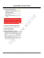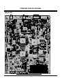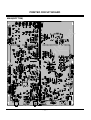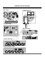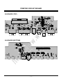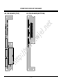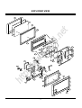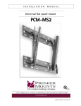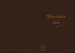
1
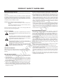
SERVICE MANUAL
t
Model Series:
P50W38
PLASMA
RF-03GB
PV155
P50W38H
P50W38P
F Line
2003
ww
.w
jel
.ne
Product Type:
Chassis:
Manual Series:
Manual Part #:
Model Line:
Product Year:
//w
CONTENTS
htt
p:
Description of Controls .................................................4
Adjustment Instructions ...............................................16
Printed Circuit Boards .................................................20
Diagrams ...................................................................25
Parts List ...................................................................27
Schematics ....................................................................
Published September 2003
by Technical Publications
Zenith Electronics Corporation
201 James Record Road
Huntsville, Alabama 35824-1513
Copyright © 2003 by Zenith Electronics Corporation
Printed in Korea
PRODUCT SAFETY GUIDELINES
When servicing this product, under no circumstances should the original design
be modified or altered without permission from Zenith Electronics Corporation.
All components should be replaced only with types identical to those in the
original circuit and their physical location, wiring and lead dress must conform
to original layout upon completion of repairs.
CAUTION: Do not attempt to modify this product in any way.
Never perform customized installations without manufacturer’s
approval.
Unauthorized modifications will not only void the warranty, but may
lead to property damage or user injury.
Service work should be performed only after you are thoroughly familiar with
these safety checks and servicing guidelines.
5. No lead or component should touch a receiving tube or a resistor rated at 1
watt or more. Lead tension around protruding metal surfaces must be avoided.
6. After reassembly of the set, always perform an AC leakage test on all
exposed metallic parts of the cabinet (the channel selector knobs, antenna
terminals, handle and screws) to be sure that set is safe to operate without
danger of electrical shock. DO NOT USE A LINE ISOLATION
TRANSFORMER DURING THIS TEST. Use an AC voltmeter having 5000
ohms per volt or more sensitivity in the following manner: Connect a 1500
ohm, 10 watt resistor, paralleled by a .15 mfd 150V AC type capacitor
between a known good earth ground water pipe, conduit, etc.) and the
exposed metallic parts, one at a time.
Measure the AC voltage across the combination of 1500 ohm resistor and
.15 mfd capacitor. Reverse the AC plug by using a non-polarized adaptor
and repeat AC voltage measurements for each exposed metallic part.
Voltage measured must not exceed 0.75 volts RMS. This corresponds to 0.5
milliamp AC. Any value exceeding this limit constitutes a potential shock
hazard and must be corrected immediately.
t
This manual was prepared for use only by properly trained audio-visual service
technicians.
.ne
IMPORTANT SAFETY NOTICE
The exclamation point within an equilateral triangle is intended to
alert the service personnel to important safety information in the
service literature.
1. Never install any receiver in a closed-in recess, cubbyhole, or closely fitting
shelf space over, or close to, a heat duct, or in the path of heated air flow.
2. Avoid conditions of high humidity such as: outdoor patio installations where
dew is a factor, near steam radiators where steam leakage is a factor, etc.
3. Avoid placement where draperies may obstruct venting. The customer
should also avoid the use of decorative scarves or other coverings that might
obstruct ventilation.
4. Wall- and shelf-mounted installations using a commercial mounting kit must
follow the factory-approved mounting instructions. A product mounted to a
shelf or platform must retain its original feet (or the equivalent thickness in
spacers) to provide adequate air flow across the bottom. Bolts or screws
used for fasteners must not touch any parts or wiring. Perform leakage tests
on customized installations.
5. Caution customers against mounting a product on a sloping shelf or in a tilted
position, unless the receiver is properly secured.
6. A product on a roll-about cart should be stable in its mounting to the cart.
Caution the customer on the hazards of trying to roll a cart with small casters
across thresholds or deep pile carpets.
7. Caution customers against using a cart or stand that has not been listed by
Underwriters Laboratories, Inc. for use with its specific model of television
receiver or generically approved for use with TVs of the same or larger screen
size.
8. Caution customers against using extension cords. Explain that a forest of
extensions, sprouting from a single outlet, can lead to disastrous
consequences to home and family.
.w
The lightning flash with arrowhead symbol within an equilateral
triangle is intended to alert the service personnel to the presence
of noninsulated “dangerous voltage” that may be of sufficient
magnitude to constitute a risk of electric shock.
jel
TIPS ON PROPER INSTALLATION
GRAPHIC SYMBOLS
SERVICE INFORMATION
ww
V
//w
A
The pictorial representation of a fuse and its rating within an
equilateral triangle is intended to convey to the service personnel
the following fuse replacement caution notice:
CAUTION: FOR CONTINUED PROTECTION AGAINST RISK
OF FIRE, REPLACE ALL FUSES WITH THE SAME TYPE AND
RATING AS MARKED NEAR EACH FUSE.
While servicing, use an isolation transformer for protection from AC line shock.
After the original service problem has been corrected, make a check of the
following:
htt
p:
FIRE AND SHOCK HAZARD
1. Be sure that all components are positioned to avoid a possibility of adjacent
component shorts. This is especially important on items transported to and
from the repair shop.
2. Verify that all protective devices such as insulators, barriers, covers, shields,
strain reliefs, power supply cords, and other hardware have been reinstalled
per the original design. Be sure that the safety purpose of the polarized line
plug has not been defeated.
3. Soldering must be inspected to discover possible cold solder joints, solder
splashes, or sharp solder points. Be certain to remove all loose foreign particles.
4. Check for physical evidence of damage or deterioration to parts and
components, for frayed leads or damaged insulation (including the AC cord),
and replace if necessary.
- 2 -
TABLE OF CONTENTS
DESCRIPTION OF CONTROLS ...........................................4
SPECIFICATIONS.................................................................6
EXTERNAL CONTROL DEVICE SETUP..............................8
.ne
t
IR CODE..............................................................................14
ADJUSTMENT INSTRUCTION...........................................16
BLOCK DIAGRAM...............................................................25
.w
EXPLODED VIEW...............................................................26
jel
PRINTED CIRCUIT BOARD ...............................................20
EXPLODED VIEW PARTS LIST .........................................27
ww
REPLACEMENT PARTS LIST ............................................28
htt
p:
//w
SCHEMATIC DIAGRAM..........................................................
- 3 -
DESCRIPTION OF CONTROLS
Controls
Front Panel Controls
ON/OFF
INPUT SELECT
.ne
t
- This is a simplified representation of front panel.
Here shown may be somewhat different from your monitor.
MENU
VOL.
E, D
Main Power Button
VOLUME (F,G) Buttons
MENU Button
Power Standby Indicator
Illuminates red in standby mode,
Illuminates green when the
Monitor is turned on.
.w
Remote Control Sensor
Buttons
jel
INPUT SELECT Button
ww
Connection Options
( )R( )
( )L ( )
RS-232C INPUT
(CONTROL/SERVICE)
1
2
DVI INPUT
RGB INPUT
AUDIO INPUT
3
RGB OUTPUT
R AUDIO L
REMOTE
CONTROL
4
htt
p:
EXTERNAL SPEAKER
//w
Back Connection Panel
1. EXTERNAL SPEAKER (8 ohm output)
Connect to optional external speaker(s).
* For further information, refer to ‘Speaker & Speaker
Stand’ manual.
2. RS-232C INPUT (CONTROL/SERVICE) PORT
Connect to the RS-232C port on a PC.
3. DVI (Digital Visual Interface) INPUT/
RGB INPUT/AUDIO INPUT JACKS
Connect the monitor output connector from a PC to the
appropriate input port.
4. RGB OUTPUT PORT
You can watch the RGB signal on another monitor, connect
RGB OUTPUT to another monitor’s PC input port.
5
AUDIO INPUT
Y
PB
PR
COMPONENT INPUT
6
R AUDIO L (MONO)
S-VIDEO
VIDEO INPUT AUDIO INPUT
7
AC INPUT
8
5. REMOTE CONTROL
Connect your wired remote control to the remote control
port on the Monitor.
6. COMPONENT INPUT/AUDIO INPUT JACKS
Connect a component video/audio device to these jacks.
7. S-VIDEO INPUTS
Connect S-Video out from an S-VIDEO port on a VCR to the S-VIDEO
input.
AUDIO/VIDEO INPUT JACKS
Connect audio/video out from external equipment to these
jacks.
8. POWER CORD SOCKET
This Monitor operates on an AC power. The voltage is indicated on the Specifications page. Never attempt to operate
the Monitor on DC power.
- 4 -
DESCRIPTION OF CONTROLS
Remote Control Key Functions
- When using the remote control, aim it at the remote control sensor on the monitor.
- Under certain conditions such as if the remote IR signal is interrupted, the remote control may not function. Press
the key again as necessary.
POWER
Switches the Monitor between
ON and STANDBY.
SLEEP
Sets the Sleep Timer.
POWER
SLEEP
ARC
Changes the picture format.
INPUT SELECT
APC
DASP
ARC
PIP ARC
PIP
TWIN PICTURE
SUB INPUT
SWAP
MENU
TWIN PICTURE
OK
SUB INPUT
Selects the input source for the sub
picture.
ww
SWAP
Exchanges main and sub picture
images.
1
2
3
4
5
6
7
8
9
0
//w
WIN. SIZE
Adjusts the sub picture size.
VOL
.w
VOL
NUMBER buttons
POWER
STOP
REW
PLAY
P/STILL
WIN.POSITION
Moves the sub picture.
ZOOM +
htt
p:
ZOOM -
MUTE
Switches the sound on or off.
OK
D /E
Selects menu option.
Memorizes menu changes.
F / G (Volume button)
Increases/decreases sound level.
Adjusts menu settings.
FF
REC
WIN.SIZE WIN.POSITION SPLIT ZOOM
SPLIT ZOOM
Enlarges the picture.
PIP ARC
Changes the PIP picture format.
MUTE
PIP
Switches the sub picture on or off.
MENU
Displays on screen menus one by one.
Exits the current menu.
DASP
To select the sound appropriate to
your viewing program character:
Flat, Music, Cinema, Sports, or User
jel
APC
Adjusts the factory preset picture
according to the room.
.ne
t
INPUT SELECT
Selects source: Video, S-Video, RGB,
DVI, or Component mode.
ZOOM-/ZOOM+
Enlarges or reduces
the main picture size.
- 5 -
VCR BUTTONS
Control some video cassette
recorders.
SPECIFICATIONS
MODELS
P50W38, P50W38H, P50W38P
48.2 / 1223
Height (inches / mm)
28.9 / 734
Depth (inches / mm)
4.1 / 105
Weight (pounds / kg)
95.2 / 43.2
Power requirement
AC120V, 60Hz
Resolution
1366 x 768 (Dot)
Color
16,770,000 (256 steps of each R, G and B)
Operating Temperature Range
32 ~ 104°F (0 ~ 40°C)
Operating Humidity Range
Less than 80%
jel
.ne
t
Width (inches / mm)
.w
Maximum Elevation
htt
p:
//w
ww
• The specifications shown above may be changed without notice for quality improvement.
- 6 -
SPECIFICATIONS
Monitor Display Specifications (RGB-PC / DVI-PC Mode)
640x480
800x600
832x624
31.500
60.00
85.08
35.000
70.00
31.469
70.08
37.500
75.00
37.927
85.03
48.363
60.00
31.469
59.94
56.476
70.06
35.000
66.66
37.861
72.80
37.500
75.00
43.269
85.00
35.156
56.25
1280x960
37.879
60.31
1280x1024
46.875
75.00
53.674
85.06
49.725
74.55
31.500
60.00
35.000
70.00
37.500
75.00
852x480
1024x768
60.023
1152x864
t
37.861
1360x768
1366x768
htt
p:
//w
ww
848x480
Horizontal
Vertical
Frequency(KHz) Frequency(Hz)
- 7 -
75.02
.ne
720x400
Resolution
54.348
60.05
63.995
70.01
67.500
75.00
60.000
60.00
63.981
60.02
47.700
60.00
59.625
75.02
47.700
60.00
59.625
75.02
jel
640x350
Horizontal
Vertical
Frequency(KHz) Frequency(Hz)
31.468
70.09
.w
Resolution
EXTERNAL CONTROL DEVICE SETUP
- Connect the RS-232C input jack to an external control device (such as a computer or an A/V control system)
and control the Monitor’s functions externally.
- Connect the serial port of the control device to the RS-232C jack on the Monitor back panel.
- RS-232C connection cables are not supplied with the Monitor.
( )R( )
Y
R AUDIO L
( )L ( )
RS-232C INPUT
(CONTROL/SERVICE)
DVI INPUT
RGB INPUT
AUDIO INPUT
RGB OUTPUT
REMOTE
CONTROL
AUDIO INPUT
PB
PR
R AUDIO L (MONO)
S-VIDEO
COMPONENT INPUT
VIDEO INPUT AUDIO INPUT
AC INPUT
.w
jel
.ne
t
EXTERNAL SPEAKER
Pin Name
No Connection
RXD (Receive data)
TXD (Transmit data)
DTR (DTE side ready)
GND
DSR (DCE side ready)
RTS (Ready to send)
CTS (Clear to send)
No Connection
5
9
6
//w
No.
1
2
3
4
5
6
7
8
9
1
ww
Type of Connector: D-Sub 9-pin Male
RS-232C Configurations
3- Wire Configuration
(Not standard)
htt
p:
7-Wire Configuration
(Standard RS-232C cable)
RXD
TXD
GND
DTR
DSR
RTS
CTS
PC
PDP
2
3
5
4
6
7
8
3
2
5
6
4
8
7
D-Sub 9
D-Sub 9
TXD
RXD
GND
DSR
DTR
CTS
RTS
RXD
TXD
GND
DTR
DSR
RTS
CTS
- 8 -
PC
PDP
2
3
5
4
6
7
8
3
2
5
4
6
7
8
D-Sub 9
D-Sub 9
TXD
RXD
GND
DTR
DSR
RTS
CTS
EXTERNAL CONTROL DEVICE SETUP
Set ID
- Use this function to specify a monitor ID number.
- Refer to ‘Real Data Mapping 1’. See page 27.
1. Press the MENU button and then use the
2. Press the
G
button and then use
D /E
D /E
button to select the SPECIAL menu.
VIDEO
button to select Set ID..
AUDIO
TIME
3. Press the G button and then use
monitor ID number.
F /G
button to adjust Set ID. to choose the desired
SPECIAL
Language
Key lock
ISM Method
Low power
Set ID.
G
1
OSD Rotate
• The adjustment range of Set ID. is 1 ~ 99.
Communication Parameters
• Stop bit : 1 bit
• Communication code : ASCII code
jel
• Baud rate : 115200 bps (UART)
• Data length : 8 bits
• Parity : None
Command Reference List
Transmission / Receiving Protocol
COMMAND 1 COMMAND 2
DATA
Transmission
a
b
c
d
e
f
g
h
i
j
k
l
m
n
o
p
q
r
s
t
u
v
w
$
y
z
p
q
r
s
t
0~1
0~4
0~3
0~1
0~1
0 ~ 64
0 ~ 64
0 ~ 64
0 ~ 64
0 ~ 64
0 ~ 64
0~1
0~1
0~3
0~1
21 ~99
0~3
0 ~ 64
0 ~ 64
0 ~ 64
0~3
0 ~ C8
0 ~ C8
0 ~ C8
0~4
0~a
0~3
0~1
1 ~ FE
0 ~9
0 ~64
j
u
1
[Command1][Command2][ ][Set ID][ ][Data][Cr]
* [Command 1]: k, j
* [Command 2]: To control PDP set.
* [Set ID]: You can adjust the set ID to choose desired monitor ID number in Special menu. Adjustment range
is 1 ~ 99. When selecting Set ID ‘0’, every connected PDP set is controlled. Set ID is indicated
as decimal (1~99) on menu and as Hexa decimal
(0x0~0x63) on transmission/receiving protocol.
* [DATA]: To transmit command data.
Transmit ‘FF’ data to read status of command.
* [Cr]: Carriage Return
ASCII code ‘0x0D’
* [ ]: ASCII code ‘space (0x20)’
htt
p:
//w
ww
k
k
k
k
k
k
k
k
k
k
k
k
k
k
k
k
k
k
k
k
k
k
k
k
k
k
j
j
j
j
j
.w
(Hexadecimal)
01. Power
02. Input Select
03. Aspect Ratio
04. Screen Mute
05. Volume Mute
06. Volume Control
07. Contrast
08. Brightness
09. Color
10. Tint
11. Sharpness
12. OSD Select
13. Remote Control Lock Mode
14. PIP/Twin
15. PIP Aspect Ratio
16. Split Zoom
17. PIP Position
18. Treble
19. Bass
20. Balance
21. Color Temperature
22. Red Adjustment
23. Green Adjustment
24. Blue Adjustment
25. PIP Input Source
26. Abnormal State
27. ISM Method
28. Low Power
29. Orbiter Time Setting
30. Orbiter Pixel Setting
31. Picture Size Setting
for Twin Picture mode
32. Auto Configure
MENU Prev.
.ne
TWIN
t
SCREEN
OK Acknowledgement
[Command2][ ][Set ID][ ][OK][Data][x]
* The Monitor transmits ACK (acknowledgement) based on
this format when receiving normal data. At this time, if the
data is data read mode, it indicates present status data. If
the data is data write mode, it returns the data of the PC
computer.
Error Acknowledgement
[Command2][ ][Set ID][ ][NG][x]
* The Monitor transmits ACK (acknowledgement) based on
this format when receiving abnormal data from
non-viable functions or communication errors.
Data 1: Illegal Code
2: Not supported function
3: Wait more time
• Menu doesn’t display on screen when setting the 4,
12, 13, and 26 ~ 32.
- 9 -
EXTERNAL CONTROL DEVICE SETUP
01. Power (Command2:a)
04. Screen Mute (Command2:d)
G To control Power On/Off of the Monitor.
G To select screen mute on/off.
Transmission
Transmission
[k][a][ ][Set ID][ ][Data][Cr]
Data 0 : Power Off
[k][d][ ][Set ID][ ][Data][Cr]
1 : Power On
Data 0 : Screen mute off (Picture on)
1 : Screen mute on (Picture off)
Acknowledgement
Acknowledgement
[d][ ][Set ID][ ][OK][Data][x]
t
[a][ ][Set ID][ ][OK][Data][x]
G To show Power On/Off.
.ne
05. Volume Mute (Command2:e)
Transmission
[k][a][ ][Set ID][ ][FF][Cr]
G To control volume mute on/off.
You can also adjust mute using the MUTE button on
remote control.
Transmission
1 : Power On
Acknowledgement
[a][ ][Set ID][ ][OK][Data][x]
[k][e][ ][Set ID][ ][Data][Cr]
* In a like manner, if other functions transmit ‘FF’ data
based on this format, Acknowledgement data feedback
presents status about each function.
jel
Data 0 : Power Off
Data 0 : Volume mute on (Volume off)
1 : Volume mute off (Volume on)
Acknowledgement
[e][ ][Set ID][ ][OK][Data][x]
Transmission
[k][b][ ][Set ID][ ][Data][Cr]
Data 0 : RGB
1 : Component
2 : Video
06. Volume Control (Command2:f)
G To adjust volume.
You can also adjust volume with the volume buttons
on remote control.
ww
G To select input source for the Monitor.
You can also select an input source using the INPUT
SELECT button on the Monitor's remote control.
.w
02. Input Select (Command2:b) (Main Picture Input)
Transmission
3 : S-video
4 : DVI
Acknowledgement
//w
[b][ ][Set ID][ ][OK][Data][x]
[k][f][ ][Set ID][ ][Data][Cr]
Data Min : 0 ~ Max : 64
• Refer to ‘Real data mapping1’ as shown below.
Acknowledgement
[f][ ][Set ID][ ][OK][Data][x]
07. Contrast (Command2:g)
G To adjust the screen format.
You can also adjust the screen format using the ARC
(Aspect Ratio Control) button on remote control or in the
Special menu.
Transmission
G To adjust screen contrast.
You can also adjust contrast in the Video menu.
htt
p:
03. Aspect Ratio (Command2:c) (Main picture format)
[k][c][ ][Set ID][ ][Data][Cr]
Data 0
1
2
3
:
:
:
:
Wide screen (16:9)
Normal screen (4:3)
Full screen (Zoom)
Horizon
Transmission
[k][g][ ][Set ID][ ][Data][Cr]
Data Min : 0 ~ Max : 64
• Refer to ‘Real data mapping1’ as shown below.
Acknowledgement
[g][ ][Set ID][ ][OK][Data][x]
Acknowledgement
* Real data mapping 1
[c][ ][Set ID][ ][OK][Data][x]
0 : Step 0
* You select either 16:9 or 4:3 screen aspect ratio using the
PC, DTV 720p/1080i.
A : Step 10 (SET ID 10)
F : Step 15 (SET ID 15)
10 : Step 16 (SET ID 16)
64 : Step 100
- 10 -
EXTERNAL CONTROL DEVICE SETUP
08. Brightness (Command2:h)
13. Remote Control Lock Mode (Command2:m)
G To adjust screen brightness.
You can also adjust brightness in the Video menu.
G To lock the remote control and front panel controls on the
monitor
Transmission
Transmission
[k][h][ ][Set ID][ ][Data][Cr]
[k][m][ ][Set ID][ ][Data][Cr]
Data Min : 0 ~ Max : 64
• Refer to ‘Real data mapping 1’. See page 27.
Data 0: Lock off
Acknowledgement
[m][ ][Set ID][ ][OK][Data][x]
[h][ ][Set ID][ ][OK][Data][x]
• If you’re not using the remote control and front panel con-
1: Lock on
t
Acknowledgement
G To adjust the screen color.
You can also adjust color in the Video menu.
.ne
trols on the monitor, use this mode. When main power is
on/off, remote control lock is released.
09. Color (Command2:i)
14. PIP / Twin (Command2:n)
G To control the PIP (Picture-in-Picture) or Twin Picture.
You can also control the PIP/Twin picture mode using the PIP
or TWIN PICTURE button on the remote control or in the
Twin menu.
Transmission
[k][i][ ][Set ID][ ][Data][Cr]
Data Min : 0 ~ Max : 64
• Refer to ‘Real data mapping 1’. See page 27.
Acknowledgement
jel
Transmission
[k][n][ ][Set ID][ ][Data][Cr]
Data 0: PIP/DW off
1: PIP
[i][ ][Set ID][ ][OK][Data][x]
2: DW1
3: DW2
.w
Acknowledgement
10. Tint (Command2:j)
[n][ ][Set ID][ ][OK][Data][x]
G To adjust the screen tint.
You can also adjust tint in the Video menu.
15. PIP Aspect Ratio (Command2:o)
G To select the PIP picture format.
You can also select the PIP picture format using PIP ARC
on the remote control.
ww
Transmission
[k][j][ ][Set ID][ ][Data][Cr]
Data Red : 0 ~ Green : 64
• Refer to ‘Real data mapping 1’. See page 27.
Transmission
Acknowledgement
Data 0: 4:3
[j][ ][Set ID][ ][OK][Data][x]
1: 16:9
//w
Acknowledgement
11. Sharpness (Command2:k)
G To adjust the screen sharpness.
You can also adjust sharpness in the Video menu.
Transmission
[k][o][ ][Set ID][ ][Data][Cr]
htt
p:
[k][k][ ][Set ID][ ][Data][Cr]
[o][ ][Set ID][ ][OK][Data][x]
16. Split Zoom (Command2:p)
G To operate split zoom function and select the split
zoom section number.
Transmission
[k][p][ ][Set ID][ ][Data][Cr]
Data Min: 0 ~ Max: 64
• Refer to ‘Real data mapping 1’. See page 27.
Acknowledgement
Data Min: 21 ~ Max: 99
• Refer to ‘Real data mapping 2’.
[k][ ][Set ID][ ][OK][Data][x]
Acknowledgement
[p][ ][Set ID][ ][OK][Data][x]
12. OSD Select (Command2:l)
* Real data mapping 2
G To select OSD (On Screen Display) on/off.
21:
24:
41:
42:
44:
45:
91:
Transmission
[k][l][ ][Set ID][ ][Data][Cr]
Data 0: OSD off
1: OSD on
Acknowledgement
[l][ ][Set ID][ ][OK][Data][x]
Selection
Selection
Selection
Selection
Selection
Selection
Selection
1
4
1
2
4
5
1
of
of
of
of
of
of
of
2
2
4
4
4
4
9
split
split
split
split
split
split
split
zoom
zoom
zoom
zoom
zoom
zoom
zoom
99: Selection 9 of 9 split zoom
- 11 -
EXTERNAL CONTROL DEVICE SETUP
17. PIP Position (Command2:q)
21. Color Temperature (Command2:u)
G To select sub picture position for PIP.
You can also adjust the sub picture position using
Win.position on the remote control or in the Twin menu.
G To adjust color temperature.
You can also adjust ACC in the Video menu.
Transmission
Transmission
[k][u][ ][Set ID][ ][Data][Cr]
[k][q][ ][Set ID][ ][Data][Cr]
Right down on screen
Left down on screen
Left up on screen
Right up on screen
1: Cool
2: Warm
3: User
Acknowledgement
[u][ ][Set ID][ ][OK][Data][x]
t
Data 0:
1:
2:
3:
Data 0: Normal
Acknowledgement
[q][ ][Set ID][ ][OK][Data][x]
.ne
22. Red Adjustment (Command2:v)
G To adjust red in color temperature.
Transmission
18. Treble (Command2:r)
[k][v][ ][Set ID][ ][Data][Cr]
G To adjust treble.
You can also adjust treble in the Audio menu.
[k][r][ ][Set ID][ ][Data][Cr]
[v][ ][Set ID][ ][OK][Data][x]
[r][ ][Set ID][ ][OK][Data][x]
.w
Data Min: 0 ~ Max: 64
• Refer to ‘Real data mapping 1’. See page 27.
Acknowledgement
jel
Transmission
Data Min: 0 ~ Max: C8
• Refer to ‘Real data mapping 3’ as shown below.
Acknowledgement
23. Green Adjustment (Command2:w)
G To adjust green in color temperature.
Transmission
ww
[k][w][ ][Set ID][ ][Data][Cr]
19. Bass (Command2:s)
Data Min: 0 ~ Max: C8
• Refer to ‘Real data mapping 3’ as shown below.
Acknowledgement
G To adjust bass.
You can also adjust bass in the Audio menu.
Transmission
[w][ ][Set ID][ ][OK][Data][x]
[k][s][ ][Set ID][ ][Data][Cr]
24. Blue Adjustment (Command2:$)
[s][ ][Set ID][ ][OK][Data][x]
G To adjust blue in color temperature.
//w
Data Min: 0 ~ Max: 64
• Refer to ‘Real data mapping 1’. See page 27.
Acknowledgement
htt
p:
20. Balance (Command2:t)
G To adjust balance.
You can also adjust balance in the Audio menu.
Transmission
[k][$][ ][Set ID][ ][Data][Cr]
Data Min: 0 ~ Max: C8
• Refer to ‘Real data mapping 3’ as shown below.
Acknowledgement
[$][ ][Set ID][ ][OK][Data][x]
Transmission
* Real data mapping 3
[k][t][ ][Set ID][ ][Data][Cr]
Data Min: 0 ~ Max: 64
• Refer to ‘Real data mapping 1’. See page 27.
Acknowledgement
0 : -20
5 : -19
A : -18
[t][ ][Set ID][ ][OK][Data][x]
5F: -1
64: 0
69: +1
C3: +19
C8: +20
- 12 -
EXTERNAL CONTROL DEVICE SETUP
25. PIP Input Select (Command2:y)
29. Orbiter Time Setting (Command2:r)
G To select input source for sub picture in PIP mode.
G To adjust orbiter operation time term.
Transmission
Transmission
[k][y][ ][Set ID][ ][Data][Cr]
[j][r][ ][Set ID][ ][Data][Cr]
Data 0: RGB
2: Video
Data Min: 1 ~ Max: FE
• Refer to ‘Real data mapping 1’. See page 27.
Acknowledgement
1: Component
3: S-video
4: DVI
Acknowledgement
[r][ ][Set ID][ ][OK][Data][x]
26. Abnormal State (Command2:z)
.ne
t
[y][ ][Set ID][ ][OK][Data][x]
30. Orbiter Pixel Setting (Command2:s)
G To recognize an abnormal state.
G To adjust pixel number in orbiter function.
Transmission
Transmission
[k][z][ ][Set ID][ ][FF][Cr]
[j][s][ ][Set ID][ ][Data][Cr]
Data FF:Read
jel
Data Min: 0 ~ Max: 9
Acknowledgement
Acknowledgement
[z][ ][Set ID][ ][OK][Data][x]
31. Picture Size Setting for Twin Picture mode
(Command2:t)
G To adjust main picture size in twin picture mode.
Transmission
ww
27. ISM Method (Command2:p)
.w
[s][ ][Set ID][ ][OK][Data][x]
Data 0: Normal (Power on and signal exist)
1: No signal (Power on)
2: Turn the monitor off by remote control
3: Turn the monitor off by sleep time function
4: Turn the monitor off by RS-232C function
5: 5V down
6: AC down
7: Turn the monitor off by Fan Alarm function
8: Turn the monitor off by off time function
9: Turn the monitor off by auto off function
a: Turn the monitor off by AV board detect
[j][t][ ][Set ID][ ][Data][Cr]
Data Min: 0 ~ Max: 64
• Refer to ‘Real data mapping1’. See page 27.
Acknowledgement
[t][ ][Set ID][ ][OK][Data][x]
Transmission
//w
G To avoid having a fixed image remain on screen.
[j][p][ ][Set ID][ ][Data][Cr]
Data 0: Normal
1: White wash
Acknowledgement
2: Orbiter
3: Inversion
htt
p:
[p][ ][Set ID][ ][OK][Data][x]
32. Auto Configure (Command2:u)
G To adjust picture position and minimize image shaking
automatically. Auto Configure only works in RGB-PC
mode.
Transmission
[j][u][ ][Set ID][ ][Data][Cr]
28. Low Power (Command2:q)
Data 1: To set
G To control the low power function on/off.
Acknowledgement
Transmission
[u][ ][Set ID][ ][OK][Data][x]
[j][q][ ][Set ID][ ][Data][Cr]
Data 0: Low power off
1: Low power on
Acknowledgement
[q][ ][Set ID][ ][OK][Data][x]
- 13 -
IR CODE
How to Connect
G Connect your wired remote control to the Remote Control port on the Monitor.
Remote Control IR Code
TC
t
G Output waveform
Single pulse, modulated with 37.917KHz signal at 455KHz
.ne
Carrier frequency
FCAR = 1/TC = fOSC/12
Duty ratio = T1/TC = 1/3
T1
G Configuration of frame
Low
custom code
jel
• 1st frame
Lead
code
High
custom code
Data code
Data code
C0 C1 C2 C3 C4 C5 C6 C7 C0 C1 C2 C3 C4 C5 C6 C7 D0 D1 D2 D3 D4 D5 D6 D7 D0 D1 D2 D3 D4 D5 D6 D7
.w
• Repeat frame
Repeat code
9 ms
ww
G Lead code
Tf
4.5 ms
0.55 ms
//w
G Repeat code
9 ms
htt
p:
2.25 ms
G Bit description
• Bit “0”
• Bit “1”
0.56 ms
0.56 ms
1.12 ms
2.24 ms
G Frame interval : Tf
The waveform is transmitted as long as a key is depressed.
Tf
Tf
Tf=108ms @455KHz
- 14 -
IR CODE
Note
jel
.ne
t
R/C Button
R/C Button
R/C Button
R/C Button
R/C Button (Power On/Off)
Discrete IR Code (Only Power On)
Discrete IR Code (Only Power Off)
R/C Button
R/C Button
R/C Button
R/C Button
R/C Button
R/C Button
R/C Button
R/C Button
R/C Button
R/C Button
R/C Button
R/C Button (RGB/DVI/Video/S-video/Component)
Discrete IR Code (Input RGB Selection)
Discrete IR Code (Input DVI Selection)
Discrete IR Code (Input Video Selection)
Discrete IR Code (Input S-video Selection)
Discrete IR Code (Input Component Selection)
R/C Button
R/C Button
R/C Button
R/C Button
R/C Button
R/C Button
R/C Button
R/C Button (PIP/TWIN Exchange)
R/C Button (4:3/16:9)
R/C Button
R/C Button
R/C Button
R/C Button
R/C Button
R/C Button
R/C Button(4:3/16:9/Zoom Mode Selection)
Discrete IR Code (Only 4:3 mode)
Discrete IR Code (Only 16:9 mode)
Discrete IR Code (Only ZOOM mode)
Discrete IR Code (Only RGB-PC mode)
.w
UP (D)
DOWN (E)
VOL+ (G)
VOL- (F)
POWER On/Off
POWER ON
POWER OFF
MUTE
Number Key 0
Number Key 1
Number Key 2
Number Key 3
Number Key 4
Number Key 5
Number Key 6
Number Key 7
Number Key 8
Number Key 9
AII INPUT SELECT
RGB
DVI
VIDEO
S-VIDEO
COMPONENT
SLEEP
OK (ç)
MENU
DASP
APC
PIP
SUB INPUT
SWAP
PIP ARC
TWIN PICTURE
ZOOM +
ZOOM Window Size
Window Position
Split Zoom
ARC
ARC (4:3)
ARC (16:9)
ARC (ZOOM)
Auto configure
//w
htt
p:
00H
01H
02H
03H
08H
C4H
C5H
09H
10H
11H
12H
13H
14H
15H
16H
17H
18H
19H
0BH
D5H
C6H
5AH
D8H
BFH
0EH
44H
43H
52H
4DH
60H
61H
63H
64H
6BH
40H
41H
69H
6AH
7BH
79H
76H
77H
AFH
99H
Function
ww
Code (Hexa)
- 15 -
ADJUSTMENT INSTRUCTIONS
O
You can check whether circuit adjustment is operated well or
not, as below.
(1) Display RGB1 to the Main picture, CVBS to the Sub
picture in the TWIN PICTURE.
(2) To check the MIN-Bias, input Full Black (0 gray) signal into
CVBS and RGB1 input port at the same time from the Pattern
Generator.
(3) To check the MAX-Bias, input Full White (255 gray) signal
into CVBS and RGB1 input port at the same time from the
Pattern Generator.
(4) Compare Black Level with White Level by eye. And if
there is no Level difference, the adjustment is completed
well.
O
Data value, which adjusted in the board, is valid until the VSC
Board is dissued and must be protected. For the protection of
data, Micom does not permit any more adjustment after
completion.
If the price which is adjusted does unavoidably and the case
must become the re-adjustment the method which it does
again with lower part is same.
These instructions are applied to all of the PDP monitor, RF03GB.
O
- After pressing the InStart Key on the Remote Control of
adjustment, the InStop Key on the Remote Control of
adjustment it confirms that the adjustment mode OSD
floats from the condition which presses the MENU button
on the Local Key and when adjustment li it presses,
becomes the Power off and it becomes initially anger. And
after the Power on it re-is adjusted again.
ww
.w
1) After receiving 100% white pattern (06CH), the receiver
must be operate prior to adjustment. (Or white condition
in HEAT-RUN mode)
2) Enter into HEAT-RUN mode
- Press the POWER ON KEY on R/C for adjustment.
- OSD display HEAT-RUN WHITE and screen display
100% full WHITE PATTERN.
.ne
(1) Because this is not a hot chassis, it is not necessary to use
an isolation transformer. However, the use of isolation
transformer will help protect test instrument.
(2) Adjustment must be done in the correct order.
(3) The adjustment must be performed in the circumstance of
25±5°C of temperature and 65±10% of relative humidity if
there is no specific designation.
(4) The input voltage of the receiver must keep 100~240V,
50/60Hz during adjustment.
(5) The receiver must be operated for about 15 minutes prior
to the adjustment.
t
2. Notes
jel
1. Application Object
[ Set is activated HEAT-RUN without signal generator in
this mode.
[ Single color pattern of HEAT-RUN mode uses to check
PANEL. (RED/BLUE/GREEN)
//w
[Caution] If you turn on a still screen more than 20 minutes
(Especially Digital pattern(13 CH), Cross Hatch
Pattern), a afterimage may be occur in the black level
part of the screen.
htt
p:
3. RGB Auto Cut-Off & MIN Bias
MAX Bias Adjustment
Each PCB Assy must be checked by Check JIG Set before
assembly. (Especially, be careful Power PCB Assy which can
cause fatal Damage to PDP Module.)
5. POWER PCB Assy Voltage
Adjustment (Va, Vs Voltage Adjustment)
5-1 Test Equipment : D.M.M 1EA
(1) Input Full White (255 Gray) signal which generated from
5-2 Connection Diagram for Measuring
Standard Equipment into RGB1 Input part.
Refer to Fig 1.
(2) Press POWER ON KEY on the servic R/C for adjustment and select
Auto Cut-Off.
5-3 Adjustment Method
(3) Press Vol. + key and operate TO SET.
(4) Original Full White screen will be seen about 3~5
(1) Va Adjustment
seconds later. And if there is a display of OK OSD, then the
1) Connect + terminal of D.M.M to Va pin of P805 and
Auto Cut-off, MIN Bias and MAX Bias adjustment will be
connect – terminal to GND pin of P805.
completed.
2)
After
turning the RV601, voltage of D.M.M adjustment as
(5) After adjustment, press Y key to save adjustment and
same as Va voltage which is on the label of the PCB Right/Top.
come out of exit the adjustment mode.
(Deviation : ±0.5V)
(2) Vs adjustment
1) Connect + terminal of D.M.M to Vs pin of P805 and connect
– terminal to GND pin of P805.
- 16 -
ADJUSTMENT INSTRUCTIONS
2) After turning the RV401, voltage of D.M.M adjustment as
6-3. White Balance Adjustment
same as Vs voltage which on the label of the PCB Right/Top.
O Operate the Zero-calibration of the CA-100, then stick sensor
(Deviation : ±0.5V)
to PDP module surface when you make adjustment.
O For manual adjustment, it is also possible by the following
P805
Va
sequence.
GND
(1) Select WHITE PATTERN of HEAT RUN mode by pressing
POWER ON KEY on service remote control then
operate HEAT RUN more than 15 minute.
(2) Supply 216Gray Level, 50% size length and breadth signal to
RGB input. (Refer to Fig 2)
(3) W/B adjustment must be adjusted only High Light and then
save the adjustment value with Y Key.
(4) To adjust High Light, stick sensor to 216 Gray Level (or 105115 Cd/m2) Pattern, press ADJ Key on R/C for adjustment
and press T, U on R/C in adjustment mode to select R-L or GL, press VOL +, - Key and adjust it until color coordination
becomes as below.
X: 0.275±0.003, Y: 0.280±0.003
Color temperature: 11,500°K±500°K
NC
Vs
t
RV401
Vs ADJ
P804
+ -
.ne
DMM
jel
RV601
Va ADJ
.w
(5) Exit adjustment mode using Y Key.
6-4. RS-232C Communication Protocol
& Transmission Parameter
ww
<Fig 1> Connection Diagram of Power Adjustment for Measuring
(1) Communication Parameter
1) Communication Protocol & Transmission Parameter
: Communication Parameter
6. White Balance Adjustment
6-1. Required Equipment
//w
Color analyzer (CA-100 or same product)
6-2. Connection Diagram of Equipment for
Measuring (Manual Adjustment)
htt
p:
R-L 70
G-L 70
R-M 128
G-M 128
R-H 216
G-H 216
COLOR
ANALYZER
TYPE;CA-100
High Light
216 Gray Level
105~115Cd/§‡
RGB Signal Input
PDP MONITOR
Window
MSPG-2100 or
MSTG-5200
<Fig 2> Connection Diagram of Manual Adjustment(High Light)
- Data Length: 8bit
- Parity: none
- Stop bit: 1bit
- Band Rate: 115200bps(UART)
- Communication code: ASCII code
[ Using Crossed(reverse) Cabel
2) Transmission $ Receiving Protocol
Transmission[Command1][Command2][][Set ID][][Data][Cr]
* [Command1]: First command to control PDP Monitor (j or
k)
* [Command2]: Second command to control PDP Monitor
(a,b,c,....)
* [Set ID]: You can adjust the set ID to choose desired
monitor ID number in special menu. Adjustment range
is 1 ~ 99. When selecting Set ID ‘0’, every connected
set is controlled.
[ Set ID is indicated as decimal (1~99) on menu and as
Hexa decimal (0x0~0x63) on transmission/receiving
protocol.
* [Data] : To transmit command data.
[ Transmit ‘FF’ data to read status of command.
- 17 -
ADJUSTMENT INSTRUCTIONS
* [Cr]: Carriage Return
ASCII code ‘0x0D’
* [ ]: ASCII code ‘space (0x20)’
Transmission
[j][a][][Set ID][][FF][Cr]
Acknowledge
[a][][Set ID][][OK][Data][x] Data:0H~64H
: Input Select (Command: b)(Input Main Picture) $ Select the
t
input signal of SET
It is Identical function ‘INPUT‘ Button on the Remote Control.
.ne
Transmission [command2[ [] [Set ID] [] [OK][Data][x]
The Set transmits ACK (acknowledgement) based on this
format when receiving normal data. At this time, if the data
is data read mode, it indicates present status data. If the
data is data write mode, it returns the data of the PC
computer.
OK Acknowledge [command2[ [] [Set ID] [] [OK][Data][x]
The Set transmits ACK (acknowledgement) based on this
format when receiving normal data. At this time, if the data
is data read mode(0xFF), it indicates present status data. If
the data is data write mode, it returns the data of the PC
computer.
: Command Reference List
jel
7-1. Required Test Equipment
(1) A jig for adjusting PC, DDC. (PC serial to D-sub.
Connection equipment)
(2) S/W for writing DDC(EDID data write & read)
(3) D-Sub 15P cable, D-Sub to DVI Connector (Connect to
DVI Jack)
7-2. Setting of Device
Relation COMMAND of factory adjustment
Command2
//w
Command1
i
i
i
i
i
i
i
i
i
l
l
l
a
b
c
d
e
f
g
h
i
j
k
l
htt
p:
30. PC-R Adjustment
31. PC-G Adjustment
32. PC-B Adjustment
33. TV-R Adjustment
34. TV-G Adjustment
35. TV-B Adjustment
36. COM-R Adjustment
37. COM-G Adjustment
38. COM-B Adjustment
39. PC-R Adjustment
40. PC-G Adjustment
41. PC-B Adjustment
7. DDC Data Input
ww
* Data [01]: illegal code
[02]: not support function
[03]: wait more time
Acknowledge[b][][Set ID][][OK][Data][x]
Data 0:RGB1, 1:Component, 2:VIDEO, 3:S-VIDEO, 4:RGB2
.w
Error Acknowledge
[command2[ [] [Set ID] [] [OK][Data][x]
The Monitor transmits ACK (acknowledgement) based on
this format when receiving abnormal data from non-viable
functions or communication errors
[k][b][][Set ID][][Data][Cr]
Data 0:RGB1, 1:Component, 2:VIDEO, 3:S-VIDEO, 4:RGB2
7-3. Preparation for Adjustment
(1) Set devices as above and turn the PC, jig on.
(2) Put S/W for writing DDC (EDID data write & read) into
operation. (operated in DOS mode.)
7-4. Sequence of Adjustment
(1) DDC Data Input for Analog-RGB
EX) R Adjustment (Command1: j, Command2: a)
$ (high)PC white balance adjustment
[j][a][][Set ID][][Data][Cr] Data:0H~64H
Acknowledge
[a][][Set ID][][OK][Data][x] Data:0H~64H
$ Currently is transmission $ receiving the R-GAIN Data
which to the EEPROM.
- 18 -
1) Put the set on the table and turn the power on.
2) Connect PC Serial to D-sub 15P Cable of JIG for DDC
Adjustment to RGB1 terminal (D-Sub 15Pin).
3) Operate S/W for DDC record and select DDC Data for
Analog RGB in Model Menu.
4) Operate EDID Write command.
5) Operate EDID Read command and check whether
Check Sum is OK.
6) If Check Sum is NG, repeat 3) ~ 4).
7) If Check Sum is OK, DDC Data for Analog-RGB input is
completed.
ADJUSTMENT INSTRUCTIONS
(2) DDC Data input for Digital-RGB
.ne
t
1) Connect PC Serial to DVI Cable of JIG for DDC
Adjustment to DVI terminal (DVI Jack).
2) Operate S/W for DDC record and select DDC Data for
Digital RGB in Model Menu.
3) Operate EDID Write command.
4) Operate EDID Read command and check whether
Check Sum is OK.
5) If Check Sum is NG, repeat 3) ~ 4).
6) If Check Sum is OK, DDC Data for Digital-RGB input is
completed.
8. Component Off-Set adjustment
8-1. Required Equipment
HD-STB (SK-010T or same product)
ww
Input the signal to HD-STB(SK-010T) and receive 14Ch.
.w
Data Download percentage case to the DVI terminal it
connects the Cable, it does not become, the DVI terminal it
leads and and the Cable Digital RGB DDC Data to Download
percentage case to the RGB terminal it connects, it does not
become. Namely, the Cable in two terminals it has the JIG
equipment which is identical and simultaneously it connects,
the Download printed style of writing does not become
jel
[ The RGB terminal it leads certainly and to Analog RGB DDC
8-2. Manual Adjustment of Off-Set
htt
p:
//w
(1) Input Video signal and Component 720P, 1080i signal of
HD-STB into Video and Component input part.
(2) Select Twin Picture by pressing ADJ twice on R/C, check
component in the main picture and Video in the sub
picture.
(3) Adjust the G-OFFSET is identical “2” the degree which is
visible of component(Main picture) and Video Input(Sub
picture) by pressing Volume +, - key.
(4) Adjust the R-OFFSET, B-OFFSET color impression of
component(Main picture) and external Input(Sub picture)
same by pressing Volume +,- key.
- 19 -
PRINTED CIRCUIT BOARD
htt
p:
//w
ww
.w
jel
.ne
t
MAIN(TOP)
- 20 -
PRINTED CIRCUIT BOARD
htt
p:
//w
ww
.w
jel
.ne
t
MAIN(BOTTOM)
- 21 -
PRINTED CIRCUIT BOARD
SPK (TOP)
jel
.ne
t
POWER SWITCH
.w
SPK (BOTTOM)
PRE-AMP(BOTTOM)
htt
p:
//w
ww
PRE-AMP(TOP)
LOCAL KEY(TOP)
LOCAL KEY(BOTTOM)
- 22 -
PRINTED CIRCUIT BOARD
ww
htt
p:
//w
AV BOARD (BOTTOM)
.w
jel
.ne
t
AV BOARD (TOP)
- 23 -
PRINTED CIRCUIT BOARD
AV FIX BOARD (BOTTOM)
htt
p:
//w
ww
.w
jel
.ne
t
AV FIX BOARD (TOP)
- 24 -
- 25 -
A/V Interface
SVHS
Scart2
Half
L/R for SVHS
Y/C
S2_V, L/R
Sync signal for R/G/B,L/R
1H R/G/B
AV1
Y/C
PAL
AV
Y/C
NTSC
IC101
CXA2089
SWITCH
IC101
CXA2089
SWITCH
L/R for SVHS,BNC
Y/C
CH0
AD9888
ADC
3.3V #3
CH1 IC201
Y/Pb/Pr
(480P¸ ¨ )
RGB /HV
IC104
OPA3682
AMP
5V #1
RGB
PC L/R
74HCT08
H/V
L/R for
Component
Scart1
R/G/B
BNC
SVHS
8
Y/C
16
STB L/R
Wired _OR
Y/C
IC101
MSP3440
Sound
Processor
IC105
L/R
LA4282
AUDIO AMP
AV
3.3V
Flash-ROM (2MByte)
IC703
MX29LV160B
IC702
K6R4016V1C
SRAM (512KB)
3.3V
IC401
VPC3230(M)
YUV 16 bit
Decoder
5V/3.3V #9 H/V/CLK/ FIELD
24
IC601
Sil160
TMDS_TX
3.3V #16
PORT_EXTEND
IC750
DS232AS
RS-232C
5VST
TXD0,1
RXD0,1
IC701
R8820LV
CPU
3.3V #13
IC752
74ACT253
5VST
9PIN
RS- 232C
¸ł
TX
Comp 480I/P,ID_AT
ID_PAL/NTSC,
FAN ALARM,KEY
IR
#: the number of the circuit schematic
t
.ne
3.3V #14
(74LVC244/74LVC574)
21PIN
For
LG
50
T.M.D.S :
Transition Minimized
Differential Signaling
8
TX0` ,TX1`
TX2` ,TXC`
PDP-50
PHIL KIM 2003.02.13
2,3 rd Pin(T1,R1)
:Control/Download
4,6 th Pin(T2,R2)
:Debugging
IC405
K4S643232E
SDRAM(8Mbyte)
3.3V #7
RGBB
Indicate even/odd
for de_interlace
IC404
FLI2310
De_interlace
3.3V/2.5V #10
YUV 16 bit
IC501
Rembrandt-I
Scaler
5V/3.3V/1.8V #11
IC502/503/504
K4S643232E
SDRAM (8Mbyte)
3.3V #12
jel
.w
U-Com
ID
Y/ Pb/Pr(480i)
1H R/G/B
IC402
74LS123
5V #9
IC302
LA7151 Y/C
SWITCH
L/R
24
RGBA
Monostable Multivibrator
Y,Pb,Pr (480p ` ) : high
Y,Cb,Cr (480i) : low
ww
K4S643232E
SDRAM(8Mbyte)
3.3V #7
FLI2310
De_interlace
3.3V/2.5V #6
Buff
T541 #6
IC301
uPD64083
3D- Comb
Y/C
9/5/3.3/2.5 #8
PC L/R
AV
VPC3230(S)
Decoder
5V/3.3V #5
YUV
(Video)
24
RGB(DTV)
24
RGB(PC)
CXA2089 L/R OUT
IC202
Sil169B
TMDS_RX
3.3V #4
//w
htt
p:
STB L/R from LST - 2200
COMPONENT Y/Pb/Pr
15Pin
D_SUB
PC- OUT
15Pin
D_SUB
PC- IN
DVI- I
D0` ,D1`
D2` ,IDK`
50"KK PDP VSC Block Diagram
BLOCK DIAGRAM
EXPLODED VIEW
300
305
301
.ne
t
303
jel
201
212
205
302
.w
202
215
203
210
213
208
211
ww
209
200
206
207
102
//w
521
214
580
101
520
551
570
530
531
550
522
htt
p:
103
540
552
560
400
410
571
541
401
590
320
310
330
- 26 -
EXPLODED VIEW PARTS LIST
No.
Part No.
101
5900V12001A
FAN,DC G1225S12B2 12X12X25 12V130MA 1500 168GM MOTOR L=260
102
4980V00781A
SUPPORTER ASSY,NON FAN(L) MN-50PZ10
103
4980V00782A
SUPPORTER ASSY,NON FAN(R) MN-50PZ10
200
6348Q-C032A
PDP,50 16:9 1365*768 KK, FOR INTERCOMPANY DOMESTIC
201
6871QRH035A
PCB ASSEMBLY,DISPLAY XRRT ASSY 50X2 X_RT 4LAYER 260MM X 280MM
202
6871QPH008A
PCB ASSEMBLY,DISPLAY DCDC ASSY KK MODEL
203
6871QZH031A
PCB ASSEMBLY,DISPLAY ZSUS ASSY 50KK 2LAYER
205
6871QLH032A
PCB ASSEMBLY,DISPLAY XRLT ASSY 50X2 X_LT 4LAYER 352.5 X 280
206
6871QXH021A
PCB ASSEMBLY,DISPLAY XRCB ASSY 50X2 X_CB 4LAYER 415.5MM X 280MM
207
6871QLH033A
PCB ASSEMBLY,DISPLAY XRLB ASSY 50X2 X_LB 4LAYER 352.5 X 280
208
6871QDH049A
PCB ASSEMBLY,DISPLAY YDRV ASSY 50WXDP2 4L(BTM)
209
6871QYH028A
PCB ASSEMBLY,DISPLAY YSUS ASSY 50KK 4LAYER
210
6871QDH048A
PCB ASSEMBLY,DISPLAY YDRV ASSY 50WXDP2 4L(TOP)
211
6871QRH036A
PCB ASSEMBLY,DISPLAY XRRB ASSY 50X2 X_RB 4LAYER 260X 280
212
6871QXH020A
PCB ASSEMBLY,DISPLAY XRCT ASSY 50X2 X_CT 4LAYER 415.5 X 280
213
6871QCH028B
PCB ASSEMBLY,DISPLAY CTRL ASSY 50X2 280*180 PD4021
215
4980V00416E
SUPPORTER,MODULE AL MN-50PZ44VS LEFT
214
4980V00416F
SUPPORTER,MODULE AL MN-50PZ44VS RIGHT
300
3091V00433Z
CABINET ASSEMBLY,MZ-50PZ45V NON RF03GB
301
4980V00361A
SUPPORTER,FILTER EGI MN-50PZ40
302
4980V00362A
303
4980V00363A
305
3790V00683B
310
5020V00688A
320
320-062H
330
5020V00645A
BUTTON,POWER OUTER MN-50PZ40 SET
400
3809V00292A
BACK COVER ASSEMBLY,MN-50PZ40 NON NON
401
3301V00016J
PLATE ASSEMBLY,A/V 3300V00163 MU-50PZ44V
410
3809V00293G
BACK COVER ASSEMBLY,MU-50PZ44 NON FOR KK
520
6871VMMR17A
ww
.w
jel
.ne
t
Description
SUPPORTER,FILTER EGI MN-50PZ40
SUPPORTER,FILTER EGI MN-50PZ40
FILTER(MECH),MN-50PZ41 115001S03E GLASS NBK MESH SINGLE AR
BUTTON,CONTROL MN-50PZ41 . SET
//w
SPRING,COIL
htt
p:
PCB ASSEMBLY,MAIN RF-03GB MU 50KK VSC MAIN 40TOOL
550
6871VSMV30A
PCB ASSEMBLY,SUB A/V RF03GB FIX BOARD
551
4980V00936A
SUPPORTER,NON EGI AV
552
4814V00388B
SHIELD,CASE MN-50PZ90V RF03GB AL AV
560
6871VSMV28A
PCB ASSEMBLY,SUB SPK RF03GB 50 KK SPK TERMINAL
570
6871VSMD08A
PCB ASSEMBLY,SUB KBD RF-02CA 50IN LOCAL KEY
571
5020V00647A
BUTTON,CONTROL S/W INNER MN-50PZ40 SET
580
3501V00084D
BOARD ASSEMBLY,POWER MN50PZ10 RF03GB SRX-75 SONY 50KK
590
6871VSMD07A
PCB ASSEMBLY,SUB P/AMP RF-02CA 50IN PRE AMP
521
522
530
531
540
541
4814V00323B
SHIELD ASSY,MN-50PZ10 NON AL BOTTOM
4814V00387A
SHIELD ASSY,MN-50PZ90V NON NON VSC TOP
6871VSMV26A
PCB ASSEMBLY,SUB PSW RF03GB 50 KK POWES S/W
5020V00648A
BUTTON,POWER INNER MN-50PZ40 SET
6871VSMV31A
PCB ASSEMBLY,SUB A/V RF03GB KK 50 A/V BOARD
4980V00729F
SUPPORTER ASSY,NON MN-50PZ90 INTERFACE
- 27 -
//w
htt
p:
t
.ne
jel
.w
ww
//w
htt
p:
t
.ne
jel
.w
ww
//w
htt
p:
t
.ne
jel
.w
ww
//w
htt
p:
t
.ne
jel
.w
ww
//w
htt
p:
t
.ne
jel
.w
ww
//w
htt
p:
t
.ne
jel
.w
ww