1
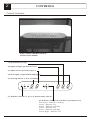
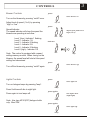
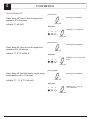
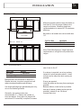
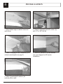
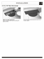
USE, CARE AND INSTALLATION GUIDE
Read all instructions before installing and operating this appliance
MODEL: TYPHOON AK2100, AK2136
IMPORTANT SAFETY NO
TICE
WARNING
Installation
The installation instruction in this manual is intended for qualified installers, service
technicians or persons with similar qualified background. DO NOT attempt to install this
appliance yourself. Injury could result from installing the unit due to lack of appropriate
electrical and technical background.
All electrical wiring should be properly installed, insulated, and grounded. Overly
accumulated grease on old duct work should be cleaned out or duct work should be
replaced if necessary to avoid the possibility of grease fire. Check all sections and joints
on duct work to insure proper connection and all joints should be properly taped.
Operations
Read all instructions in this manual before operating the appliance. Save these
instructions for future reference.
ALWAYS leave safety grills attached in place at all times. Operating blowers could catch
on to hair, fingers, and loose clothing.
Keep unit and residue containers clean from grease accumulation from time to time.
NEVER dispose foreign substances into the blowers. Do not dispose cigarette ashes or
ignitable substances into the blowers.
Cleaning
Use with extreme caution while performing the Self Cleaning Function and safety grills
are removed. Beware of fingers, hair, loose clothing from getting in the blowers and
NEVER leave children unattended.
NEVER disassemble parts to clean without proper instructions. Disassembly are
recommended to be performed by qualified personnel only. We are not responsible for
injury due to negligence and the warranty of the unit automatically expires due to
improper maintenance. Call our Service Center for removal instructions.
2
CONTROLS
Controls Overview
Zephyr Model AK2100 & AK2136
Touch Control Module
(A) turns blowers on/ off
(B) adjust to higher speed level (1 to 6)
(C) adjust to lower speed level (6 to 1)
(D) turns lights on/off and dim (night light)
(E) shuts off hood in 5, 10 or 15 minutes
5
10
minutes
15
1
delay off
2
3
low
high
on/off
lamp
(F) Indicator: indicates 5, 10, or 15 minutes delay when lit
(G) Indicator: indicates level of blower speed from 1 to 6
Level 1(low) -Indicator 1 flashing
Level 2 - Indicator 1 lit
Level 3 - Indicator 2 flashing
Level 4 - Indicator 2 lit
Level 5 - Indicator 3 flashing
Level 6 (high) - Indicator 3 lit
3
CONTROLS
Blower Controls
press:
turns blowers on
Turn on the blowers by pressing “on/off” once.
Adjust level of speed (1 to 6) by pressing
“high” or “low”.
on/ off
press:
Speed Indicator
The speed indicator will show the speed the
blowers are operating at as follow:
Level 1(low) -Indicator 1 flashing
Level 2 - Indicator 1 lit
Level 3 - Indicator 2 flashing
Level 4 - Indicator 2 lit
Level 5 - Indicator 3 flashing
Level 6 (high) - Indicator 3 lit
adjust speed from low to
high (1 to 6)
low
high
indicator:
1
low
Note: The control is equipped with a speed
setting memory module. When turning on the
blowers, the speed level will start at the speed
setting last memorized.
2
3
high
press:
turns blowers off
Turn off the blowers by pressing “on/off” again.
on/ off
Lights Controls
press:
turns lights on
Turn on halogen lamps by pressing “lamp”.
Press 2nd time will dim to night light.
lamp
press again:
Press again to turn lamps off.
Note: Use type HR16 (E27) halogen bulbs
only. Max 35W
turn lights down
(night light)
lamp
press again:
turns lights off
lamp
4
CONTROLS
Timed Delay Off
press once:
turns off in 5 minutes
Press “delay off” once to turn all range hood
operation off in 5 minutes.
delay off
Indicator “5” will be lit
Indicator
indicator “5” will be lit
5
10
15
delay off
press twice:
turns off in 10 minutes
Press “delay off” twice to turn all range hood
operation off in 10 minutes.
delay off
Indicator “5” & “10” will be lit
Indicator
5
10
indicator “5” & “10” will
be lit
15
delay off
press again:
Press “delay off” the third time to turn all range
hood operation off in 15 minutes.
turns off in 15 minutes
delay off
Indicator “5”, “10” & “15” will be lit
Indicator
5
10
indicator “5”, “10” &
“15” will be lit
15
delay off
5
INSTALLATION
CLEARANCES
Minimum clearance above range should be no
less than 18“ from the range surface to the
range hood’s base. Maximum height are
recommended not to exceed 30” for maximum
efficiency.
net width
MIN. 18” MAX 30”
Net width on all models are call out width less
1/4”.
Call Out Size
30”
36”
Net Width
29-3/4”
35-3/4”
Note: Refer Manufacturers’ height clearance
requirements on all high btu and professional
ranges.
DUCT REQUIREMENT
size of duct to 8 or 9”.
Duct Type
Duct Size
Duct opening
Round
7” Minimum
Vertical
Minimum duct size should be no less than 7”.
Smaller duct size, long duct run and turns will
reduce hood performance and efficiency.
Use single wall ridgit type galvanized pipes only,
do not use flexible type ducts.
Generally, use minimum duct size
recommended (7”). Reduce the number of
turns and bends. If long duct run (beyond 20’
vertical and 35’ horizontal) is required, increase
If a reducer is required, use a long reducer
instead of a short pancake reducer. Install
reducers as far away from duct opening as
possible.
If turns are required:
Install first elbow as far away from opening as
possible.
Between elbows, install as far as possible.
Use two 45 elbow (installed as far apart as
possible), instead of one 90 elbow.
Increase duct size.
6
INSTALLATION
DUCT OPENING
C/L
Wall
Front
8”
(min. cutout)
Rear
Rear
9”
9-1/2”
7”
Wall
Front
C/L
30” & 36” models (AK2100, AK2136)
ELECTRICAL & DRILL LOCATIONS
C/L
Electrical K/O (3/4”)
30” models (AK2100)
Wall
1-13/16”
1-3/8”
Rear
10-5/16”
3-3/4”
7”
13-7/8”
Front
C/L
30”
C/L
Electrical K/O (3/4”)
36” models (AK2136)
Wall
1-13/16”
2”
Rear
13-1/8”
10-5/16”
7”
16-7/8”
Front
C/L
36”
7
INSTALLATION
Preparing with Template
CABINET FRONT
CABINET REAR
Fold and align this edge to cabinet base and wall corner
WALL
Use template provided, fold/ or cut along inside edges.
(A)
CABINET FRONT
(A)
hanging bolt
drill location
CABINET REAR
Fold and align this edge to cabinet base and wal lcorner
(B)
wall bracket
WALL
(B) drill location
Fold along line marked “Fold and align this edge to cabinet base and wall
corner”.
**Note: Do not mistake with edge marked “Cabinet Rear”.
8
INSTALLATION
1. Align folded edge to cabinet base and
wall corner
4. Remove template and drill location (A)
with 1/4” or 3/8” drill bit.
2. Mark 2 hanging bolt drill locations (A) on
cabinet (see template on page 7).
5. Install EZ anchors to (B) as marked.
(see next diagram for EZ anchor
installation).
3. Mark 2 bracket drill locations (for
anchors) (B) on wall.
INSTALLATION
EZ Anchors
6. Tap EZ anchor tip into marked drywall
locations, turn with screwdriver until seated
flush.
9
Electrical Connection
8. Pry open 3/4” electrical knock out
Note: use EZ anchors provided only on
hollow drywall applications (minimum
drywall thickness 1/2”). If a stud or wood
surface is present, fasten anchors with
screws directly into stud or plywood. For all
other wall types (concrete, brick, tiles etc.),
use appropriate anchors for mounting.
9. Connect power source to hood (make
sure power source is turned off).
7. Fasten 2 wall brackets provided onto
anchors
DANGER
All electrical work must be performed by
qualified electricians only. Do not attempt to
wire the appliance if you are inexperience
with and/ or without proper electrical
working background and qualifications.
All electrical work must meet local codes and
requirements for safety.
10
INSTALLATION
Electrical Connection
Wall
Rear
Cable lock
Front
A cable locking connector (not supplied) is also required by local codes. Check with local requirements and codes,
purchase and install the appropriate connector in order to meet all mandatory codes.
10. Insert bolts w/ washers provided
through drill out (A)
12. Tilt hood up and fasten left and right
bolts onto hood
11. Lift hood and hook rear opening slots
onto 2 rear brackets previously installed on
wall
13. Connect duct to hood opening, tape all
joints with aluminum duct tape and inspect
for leakage
11
12
13
14
CLEANING & MAINTAINANCE
Self Clean Feature
All Zephyr model AK2100 & 2136 hoods are filter-less and are designed with a self clean
feature. The centrifugal blower system automatically liquefies cooking residue accumulated in
its internal housing. All systems are equipped with dishwasher safe clean cups for its self
clean function.
Cooking residue are often automatically liquefied and can accumulate in the clean cups from
everyday use. Nevertheless, grease from cooking could also dry and adhered in its internal
housing. Running the self clean function periodically will flush out accumulated residue in the
range hood’s internal housing.
Cleaning Frequency
Cleaning should be approximately once a month under normal use.
Detergent
Grease cutting detergent such as ‘409’ or its equivalent are recommended.
Cleaning
Safety Grill
Remove both safety grills for cleaning by
simply loosening Philips screws. Clean safety
grills in dishwasher under normal wash cycle.
WARNING: Use with extreme caution as both
safety grills are removed. Beware of blowers
catching on to hair, loose clothing, and fingers.
NEVER leave children unattended.
set to lowest speed:
Self Clean
Turn both blowers on lowest speed for
cleaning.
1
Set Timed Delay Off to 5 minutes as indicated.
2
3
high
low
set to 5 min. delay off:
5
10
15
delay off
CLEANING & MAINTAINANCE
With nozzle on ‘spray’, squirt ‘409’ detergent
directly onto blower blades 30-35 times.
Repeat with second blower. Allow self
cleaning to complete in 5 minutes. (If desired,
spray water to rinse off detergent after completion of the
cleaning cycle and run for another few minutes)
Remove clean cups. Clean w/ mild detergent
or in dishwasher under normal wash cycle.
Cleaning Tip:
Fill residue containers ¼ full with water before cleaning or during regular use. This will
help to prevent residue from drying and tacking on cup surface.
Replacing Light Bulbs
Light bulbs (included) are 35W halogen (TYPE
HR16 )bulbs.
Remove by unscrewing light bulb counter
clockwise, and replace with type HR16-35W
halogen bulbs.
Surface Maintanance
Clean all surface residue with ‘409’ or mild
detergent and wipe with cotton cloth.
Stainless steel surface could further be clean
and polished with any stainless steel polish or
glass cleaners.
15
16
TROUBLE SHOOTING
1.
Upon completion of installation,
nothing works.
Check if unit has been plugged in, make sure that all power
has been turned back on and all electrical wiring are
properly connected.
2.
Light is on but blowers are not
turning at all or seems to be scraping on
something.
Blower blade unit might have been mounted too low and
scraping the bottom or jammed. Loosen hex screw on
blade unit and adjust to proper height.
3.
When blowers are on, something
seems to be loose and spinning
around inside.
There might have been foreign particles left within the
discharge opening or rocks, leaves, branches, etc. that
might have fell in from old duct work. Disconnect duct work
to inspect and remove any foreign particles.
4.
Vibration when blowers are on
Unit might not have been secured properly on cabinet. Or
cabinet might need to be further secured into studs on wall.
5.
Blowers noise
6.
Light is not working
Light bulb might need to be replaced. On some instances,
the fragile bulb could have been damaged during the
shipping process. Replace light bulb.
7.
No grease is collected in the clean cups
Grease flow will vary by the amount, methods and types of
cooking. If pan-frying is frequent accompanied by
steaming, vapor from steam will liquefy accumulated
grease in its internal housing and flows in the clean cups.
No grease collected in the residue containers is normal
until the self clean function is completed. Clean blowers
approximately once a month as instructed to avoid
clogging.
8.
No grease is collected in the residue
containers after self cleaning.
Tubes connected to the internal housing might have been
clogged due to lack of cleaning. Or hood might not have
been leveled when installed. Unclog tubes or re-install
hood
9.
Safety grill are dirty
The self clean feature cleans only the internal housing
within the range hood. Remove safety grill to clean in
dishwasher and clean all surface periodically as instructed.
10.
Blowers seemed weak
Check duct size used, duct size should be at least 7“ .
Range hood WILL NOT function properly with the
insufficient duct size.
Check if duct is clogged or if damper unit is not opening
properly. A tight mesh on a side wall cap unit might also
cause restriction to the air flow.
Our blowers are designed to perform up to 850 cfm. A
properly functioning motor itself should be relatively quiet.
Nevertheless, due to vacuum created by the suction, noise
level up to 6 sones will be generated when both blower unit
is turned on at its maximum speed. Employ both blowers at
maximum speed only when needed (heavy pan frying,
wok cooking etc.) Employing low speeds will suffice
moderate cooking such as steaming, broiling etc.
TROUBLE SHOOTING
17
Use a damper type sidewall cap.
Reduce the number of elbows and length of duct work or
increase duct size (see page 5).
Check if all joints are properly connected, sealed and
taped.
11.
Cooking fumes and smoke dissipates
before it reaches the blower.
Check if unit is installed at the recommended height
(page 5). The range hood should also be able to cover
the entire cooking area from left to right and most areas
from rear to front.
Open doors and windows might also distract air flow
before it reaches the blowers.
Make sure blowers are on high speed for heavy cooking.
NOTES
For other questions and further assistance please call our service department with
the product’s registered serial number or write to:
ZEPHYR CORPORATION
Service Department
1.888.880.VENT (8368) 415.282.1211
1551 Minnesota Street. San Francisco, CA 94107