1
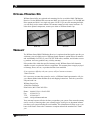
Installation
Guide &
User
Manual
PERSONAL PA® FM Monitor Receiver
Model R801
R801 Professional FM Auditory Assistance Receiver
Williams Sound
Frequency Synthesized, Channel-Selectable
Power
Frequency
72.5 72.7
72.3
Carrier
72.9
72.1
74.7
75.9
75.3
75.7 75.5
Squelch
Phones
For use with Transmitter Models:
PPA T4, PPA T17, PPA T20, PPA T16,
PFM T30, PFM T31
MAN 098B
®
Williams
Sound
Helping People Hear
PERSONAL PA® FM MONITOR RECEIVER
MODEL R801
INSTALLATION AND USER MANUAL
Contents
Page
System Overview
3
System Components
3
Quick Start Instructions
4
R801 Receiver Features
5
Optional Antennas
6
Setting the Squelch Control
7
Changing Frequencies
7
Using Multiple Systems
8
In Case Of Difficulty
8
Optional Rack Mounting Kits
9
Warranty
9
Receiver Specifications
10
2
Williams
Sound ®
Helping People Hear
SYSTEM OVERVIEW
Thank you for purchasing the PERSONAL PA® FM Monitor Receiver from Williams Sound
Corp. This monitor receiver is intended to be used for hearing assistance with a Williams
Sound PERSONAL PA Transmitter operating on one of 10 wideband channels from 72 - 76
MHz. The Monitor Receiver provides a convenient way to receive the PPA Transmitter
broadcast in a remote location. Depending the antennas being used, the receiver will operate
up to 500 feet from the transmitter
To avoid difficulties, please read through these instructions as you begin to use the system.
Then save them for questions that arise as you continue to use your Williams Sound Monitor
Receiver.
If you have problems with the system, don’t hesitate to call us toll-free at 1-800-843-3544.
SYSTEM COMPONENTS (R801)
•
FM Receiver (R801)
•
Power Supply (TFP 016)
•
“Rubber Duck” Antenna (ANT 021)
•
1m RCA to RCA Audio Cable with RCA to 1/4” Adapter (WCA 013/CNA 007)
•
Instruction Manual (MAN 098)
FIG. 1: OVERALL SYSTEM DIAGRAM
R801 Professional FM Auditory Assistance Receiver
PPA T4 Professional FM Auditory Assistance Transmitter
Phones
Audio Adjust
Power
Power
Audio Level
-12dB -6dB 0dB +6dB
Decrease
Williams Sound
Frequency Synthesized, Channel-Selectable
Frequency Synthesized, Channel-Selectable
RF Carrier
Frequency
72.5 72.7
72.3
74.7
75.9
Increase
Lo
Ok
Ok
Too Hi
PPA Transmitter
Carrier
72.9
72.1
75.3
75.7 75.5
Squelch
Phones
R801 Receiver
Amplifier
Speakers
HOW IT WORKS:
The PPA Transmitter produces the FM radio signal. The R801 picks up the transmitterd
signal and feeds it into a sound system.
Williams
Sound ®
Helping People Hear
3
QUICK START INSTRUCTIONS
1. Make sure the R801 Receiver is set to the same operating frequency as your transmitter.
See the transmitter instructions for frequency identification. Alternately, see step 6 below.
2. Choose a location for the R801 Receiver. Take into account proximity to the sound
system, availability of AC power, rack mounting,and antenna installation requirements.
3. Install the Antenna. The rubber duck antenna threads into the hole on top of the receiver.
Remote antennas connect to the “F” type connector on the rear of the R801. See page 6
for remote antenna installation details.
4. Plug the Power Supply connector into the R801. The locking tab on the connector should
point UP as shown on the R801 rear panel. Plug the power supply into an AC outlet.
5. Connect the R801 Receiver to the audio input of your sound system, using the audio
cable provided. The cable provided is for an unbalanced connection. If you wish to use a
balanced connection, you will need to supply your own TRS cable.
6. Turn the R801 Power switch ON. Change the R801 Channel Selector until the Carrier
light turns on and you hear the transmitter signal in the headphone jack.
7. Adjust the squelch control. See page 7 for details.
8. Set the volume on your sound system.
4
Williams
Sound ®
Helping People Hear
R801 MONITOR RECEIVER FEATURES
R801 FRONT PANEL FEATURES
R801 Professional FM Auditory Assistance Receiver
Williams Sound
Frequency Synthesized, Channel-Selectable
Power
Frequency
72.5 72.7
72.3
Carrier
72.9
72.1
74.7
75.9
75.3
75.7 75.5
Phones
Squelch
POWER ON/OFF SWITCH
Turns R801 power on or off.
POWER LED INDICATOR
Glows when the R801 power is on.
FM FREQUENCY SWITCH
The selected receiver channel must match the transmitter channel. The system is pre-set to
72.9 MHz. Change the receiver channel only if the transmitter channel has been changed. See
your Transmitter instructions to change the transmitter channel.
FM CARRIER LED INDICATOR
Glows when a carrier frequency is present.
PHONES JACK
Allows monitoring the audio signal with mono or stereo headphones. (1/4” TRS)
SQUELCH ADJUST
Sets Receiver incoming signal mute level.
R801 REAR PANEL FEATURES
Balanced
or Unbalanced
Line Out
Professional FM Auditory Assistance Receiver
Williams Sound Corp., Minneapolis, MN USA
Antenna
Power In
Plug
24 VAC
50-60 Hz
75 Ohms
LINEOUTPUT
This 1/4” TRS jack provides a balanced or unbalanced line-level audio output. Connect the
Tip or Ring to the Sleeve for an unbalanced signal. Connect to Tip (+) Ring (-) and Sleeve
(Com) for a balanced signal.
REMOTE ANTENNA CONNECTOR
“F–type” connector for 75Ω Remote Antennas (ANT 005, ANT 024)
AC POWER SUPPLY
Molex-type connector for TFP 016 Power Supply.
FLEXIBLE “RUBBER DUCKIE” ANTENNA
Threads onto the mounting stud on top of the receiver. ANT 025 may also be used.
Williams
Sound ®
Helping People Hear
5
USING AN ALTERNATE ANTENNA
The operating range of the system is dependent on which antenna is used on the Receiver
AND which antenna is used on the base-station Transmitter. The standard ANT 016 Rubber
Duckie Antenna on both Receiver and Transmitter will provide sufficient operating range
(up to 300 ft) for most applications. Three optional antennas are also available which will
extend the operating range and offer some installation alternatives:
ANT 005 Coaxial Antenna
When used on the Transmitter and the Receiver, this optional 80” dipole wall mount antenna
provides the greatest range (up to 500 ft.).
ANT 024 Dipole Antenna
This optional antenna provides nearly the operating range of the ANT 005 Coax Antenna,
but is easier to install and is shorter.
ANT 025 Whip
This 40” whip antenna threads onto the mounting stud on top of the receiver or Transmitter.
It provides improved range (350 - 400 ft.) compared to the standard ANT 016 antenna.
ANT 005
ANT 024
REMOTE ANTENNA LOCATION TIPS
þ
Install the ANT 005 or ANT 024 with its elements vertical. The antenna is best installed
on a wall 10 to 15 feet above the floor. It may be located in the next room from the listening area if the separating wall does not contain metal lath, steel studs, foil-backed
insulation, or significant ductwork. Do not install the antenna in an organ chamber. The
numerous pipes of an organ significantly deflect and absorb the radio signal.
þ
The ANT 005 and ANT 024 feedline is classified under the National Electrical Code as
Class II wiring and may be installed in conduit with other Class II wiring. It SHOULD
NOT be installed with Class I (power) wiring.
þ
Do not connect the coaxial cable to the building or electrical ground in any way.
AVOIDING UNDESIRABLE ANTENNA INSTALLATIONS
Transmission (range, directional properties) can be severely impaired by improper installation of the antenna.
6
þ
DO NOT install the antenna within any metal enclosure.
þ
DO NOT install the antenna where it is separated from the listening area by any substantial metal object, such as heating ducts, structural steel, foil backed insulation, steel
studs or metal lath.
Williams
Sound ®
Helping People Hear
SETTING
THE
SQUELCH CONTROL
The squelch control sets the incoming signal level required to un-mute the R801. If the
receiver is not locked onto a signal, it can produce noise. The function of the squelch circuit
is prevent this noise when no signal is present., When the squelch is properly adjusted, turning off the Transmitter will cause the R801 to mute. The radio noise in each area is different,
so you must adjust the squelch when the R801 is installed.
1. Make sure the R801 is plugged in, turned on, and has an antenna attached.
2. Make sure the Transmitter is OFF.
3. Use headphones to listen to the R801 Phones Jack.
4. Set the R801 Frequency Selector to the desired channel.
5. While listening to the headphones with the Transmitter still OFF, turn the Squelch control
counter-clockwise until noise is heard in the headphones.
6. Slowly turn the Squelch control clockwise just until the noise disappears.
7. Turn the Transmitter ON. The signal in the headphones should be clear and free from
noise and interference, unless you are out of range of the Transmitter.
8. Turn the Transmitter OFF. The R801 should immediately go silent. Re-adjust the squelch
control if necessary.
CHANGING FREQUENCIES/IF YOU EXPERIENCE INTERFERENCE
If you experience FM signal interference, you can easily adjust your transmitter and receiver
to a use different frequencies. The Transmitter and Receiver Frequencies must always
match.
CHECKING
FOR A CLEAR CHANNEL:
The R801 can be used to “scan” for a clear channel in your area. With the Transmitter
turned OFF, Move the Frequency Selector switch on the front panel of the R801 and observe
the Carrier indicator light, while listening with headphones plugged into the PHONES jack.
If it comes on, that indicates another transmitter is operating on that channel in your area.
You should select another channel to use.
CHANGING THE R801 RECEIVER FREQUENCY:
1. Simply select an alternate channel with the Frequency Selector switch on the front panel.
The selector knob shows which frequency you have selected.
2. Make sure the Transmitter matches the Receiver channel. See your Transmitter
intructions.
Williams
Sound ®
Helping People Hear
7
USING MULTIPLE CHANNELS:
1. Multi-channel systems require a Transmitter and a Receiver for each channel.
2. Make sure each Transmitter matches each Receiver channel. See your Transmitter
intructions.
3. You may be able to use adjacent channels in multi-channel systems if the R801 is the
only receiver used. Other PPA Receivers cannot use adjacent channels.
4. You may use more than one receiver with each Transmitter.
5. To avoid interference, DO NOT operate two transmitters on the same channel in the same
room.
IN CASE OF DIFFICULTY
IF NO SOUND IS PRODUCED
1. Make sure the Transmitter and Receiver are ON and operating on the same channel. If
the Transmitter has a Phones jack, listen to make sure the Transmitter has a signal.
2. Make sure the receiver carrier light is ON. If it is not, there is either no transmitter signal,
the receiver is set to the wrong channel, the receiver is out of range for the transmitter, or
there is a fault with the receiver.
3. Make sure the antenna is installed properly. If the receiver is out of range, the ANT 005
or ANT 026 remote antenna may be needed. Try moving the transmitter and receiver
closer together.
4. The squelch control may not be set properly. Try turning the control counter-clockwise to
see if the Carrier light comes on and the signal comes through.
5. Listen to the signal at the headphone jack on the R801. If there is no signal, there is
either no Transmitter signal or there is a fault with the R801. If there is a good signal at
the headphone jack, but not through your sound system, check the cable and audio
connection between the R801 and the sound system.
IF INTERFERENCE OCCURS
1. Do not try to use more than one transmitter on the same channel in close proximity to
each other. Use separate channels for each Transmitter used.
2. If you are still hearing interference on the receiver, turn the transmitter off and listen with
a receiver. If you hear the interference with the transmitter off, you need to change to a
clear channel. See the frequency change instructions on page 7.
IF PROBLEMS REMAIN
If none of the remedies above provides the solution, call Williams Sound’s Customer
Service Department at 1-800-843-3544 (8:00 AM– 4:30 PM Central Time).
8
Williams
Sound ®
Helping People Hear
OPTIONAL MOUNTING KITS
Williams Sound offers two optional rack mounting kits for use with the R801 FM Monitor
Receiver. Use the RPK 005 Kit to mount one R801 in a single rack space. Use The RPK 006
Kit to mount two R801’s in a single rack space. NOTE: If you are rack mounting the R801,
you will likely need a remote antenna. The antenna cannot be inside a metal enclosure. To
order these optional components, contact your dealer or Williams Sound Corp.
RPK 005
RPK 006
WARRANTY
The Williams Sound R801 FM Monitor Receiver is engineered and designed to provide you
with many years of reliable service. Williams Sound warrants it against defects in materials
and workmanship for FIVE (5) years EXCEPT FOR cables, antennas, and all other accessory products. Accessory products carry a 90 day warranty.
If the product fails within the specified warranty period, Williams Sound will determine
whether to repair or replace the defective equipment. This warranty does not apply to physical damage, abuse, mis-use, or products that have been modified.
If you experience difficulty with your system, call for Customer Assistance:
1-800-328-6190.
If it is necessary to return the system for service, a Williams Sound representative will give
you a Return Authorization Number (RA) and shipping instructions. Pack the system carefully and send it to:
Williams Sound Corp.
10399 West 70th Street
Eden Prairie, MN 55344-3459 USA
Phone:
Fax:
TTY:
e-mail:
800-843-3544 / 612-943-2252
952-943-2174
952-943-9675
[email protected]
Your warranty becomes effective the date you purchase your system. Your returned warranty
card is our way of knowing when your warranty begins. It also gives us important information about your system including the serial number. This information will help us serve you
better in the future. Please take a moment to complete and mail the attached card. Thank
you.
Williams
Sound ®
Helping People Hear
9
PERSONAL PA® FM MONITOR RECEIVER SPECIFICATIONS
MODEL R801
Dimensions, Weight:
1.75" H x 8.45" W x 8.25" D, 3lbs.
Color:
Black epoxy paint with white legends
Rack Mount:
One EIA rack space high, 1/2 space wide, 1-2 units can be mounted in a single rack space
with optional RPK 005 (single) or RPK 006 (double) Rack Mount kits.
Power:
24VAC, 50/60Hz, TFP 016 supplied, Molex connector
Power Indicator:
Green LED, Front panel
Operating Freq.:
10 Channel Selectable (72.1, 72.3, 72.5, 72.7, 72.9, 74.7, 75.3, 75.5, 75.7, 75.9 MHz*)
Freq. Accuracy:
0.01%, Frequency Synthesized, Crystal Reference
FM Deviation:
+/- 75kHz, 75µS de-emphasis
Sensitivity:
0.8µV at 12 dB Sinad with squelch at minimum
Carrier Indicator:
Green LED, Front panel
Freq. Response:
50 to 18kHz, +1, -4 dB
Signal/Noise Ratio:
60 dB at 100µV.
Receiver Antenna:
Flexible “rubber duckie” type or optional 75 Ohm remote antenna
Controls:
Power On/Off, FM Channel, Squelch.
Distortion:
less than 1.0% at rated power
Phones Output:
1/4” TRS, 10mVrms @ 50 Ohms impedance.
Line Output:
1/4” TRS, Balanced (Tip is positive, Ring is negative, Sleeve is common) or Unbalanced (Tip or
Ring can be connected to the Sleeve), nominal output: +4dBm @ 600 Ohms, 1.2Vrms
Additional Notice:
This device complies with the requirements of Industry Canada (IC), as specified in document RSS-210. The device is
permitted only on a no-interference no-protection basis, that is, it must cease operation when it is determined (such as
by turning the device on and off) that it causes harmful interference to services authorized by IC. Authorized services are
listed in the Canadian Table of Frequency Allocations or as determined by IC from time to time. Also, the operator must
accept any radio interference received, including interference that may cause undesired operation of the device.
Williams Sound Corp.
10399 West 70th St., Eden Prairie, MN 55344-3459
U.S.A. 800-328-6190 / 952-943-2252 / FAX: 952-943-2174
www.williamssound.com
10
© 2000, Williams Sound Corp.
MAN 098 B
Williams
Sound ®
Helping People Hear