1
Review is only for general conformance with the
design concept of the project and general
compliance with the information given in the contract
documents. Any action shown is subject to the
requirements of the plans and specifications.
Contractor is responsible for: Dimensions, which
shall be confirmed and correlated at the job site;
fabrication processes and techniques of construction;
coordination of his work with all other trades and the
satisfactory performance of his work.
X
NO EXCEPTIONS TAKEN
NOTE MARKINGS
NOTE MARKINGS - RESUBMIT
REJECT
PETER BASSO ASSOCIATES, INC.
SUBMITTAL PACKAGE 2 of 2
ELEC BY
JAM
DATE
01/18/12
MECH BY
MK
DATE
01/18/12
T.C. BY
PRODUCT: BALDOR IDLC350 DIESEL GENERATORS
PROJECT NAME: COMPUTER SERVICES CENTER / ELECTRICAL AND HVAC UPGRADE
WSU PROJECT #: 193-15987 – ACCOUNT NO. 7-71394
BY: Scott Proux
Sales Manager
Preventive Maintenance Technologies
MECHANICAL REVIEW
ELECTRICAL REVIEW
Review is only for general conformance with the
design concept of the project and general
compliance with the information given in the contract
documents. Any action shown is subject to the
requirements of the plans and specifications.
Contractor is responsible for: Dimensions, which
shall be confirmed and correlated at the job site;
fabrication processes and techniques of construction;
coordination of his work with all other trades and the
satisfactory performance of his work.
X
NO EXCEPTIONS TAKEN
NOTE MARKINGS
X
NOTE MARKINGS - RESUBMIT
REJECT
PETER BASSO ASSOCIATES, INC.
ELEC BY
JAM
DATE
01/09/12
MECH BY
PLD
DATE
01/09/12
T.C. BY
DATE
WARRANTY FOR GENERATORS TO BE ASSIGNED TO ELECTRICAL CONTRACTOR.
GENERATOR SUPPLIER TO COORDINATE DEKLIVERY OF GENERATORS WITH
ELECTRICAL CONTRACTOR.
FINAL PAYMENT FOR GENERATORS WILL BE MADE BY WAYNE STATE UNIVERSITY
DIRECTLY TO GENERATOR SUPLLIER AFTER CONSENT FOR PAYMENT HAS BEEN
GIVEN BY THE ELECTRICAL CONTRACTOR.
DATE
Corporate - 29395 Wall St. Wixom, MI 48393
West MI - 2385 Wilshere Drive Jenison, MI 49428
800.419.5199
Fax: 248.374.6408
Got Power? Generator Sales, Service & Rental
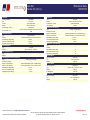
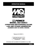
BILL OF MATERIAL
(2) BALDOR 350 KW DIESEL GENERATORS
Model
Engine Manufacturer
Frequency / Speed (RPM)
Ambient (Min/Max)
IDLC350-3DU
Detroit
60 Hz / 1800
-18 °C / 40 °C
Duty / Alt Temp Rise
Engine Model
Engine Control Voltage (DC)
Elevation
Standby / 105 °C
6063HV35
24
1000 Ft
Genset Agency Approval
Emissions Standard
Fuel Type
Enclosure / Mount Method
UL2200 / CUL
Tier 3 Emergency
Diesel
Enclosed / Skid Mounted
Output Rating (kw/kva)
Full Load Amps
Voltage (L-L/L-N) - Connection
Phase / Power Factor
350 KW / 438 KVA
526A
480/277 - Hi Wye
Three / 0.80
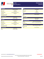
Additional Specifications:
PRODUCT
Emissions Application:
EPA Stationary Emergency
ALTERNATOR
Alternator Regulator:
MX341-UL
Drip shield:
IP22
UL 2200 RATING SHALL BE FOR ENTIRE
PMG
Alternator Excitation:
PACKAGED UNIT
Alternator Model Number:
HCI434F-311
Alternator Agency Approval:
UL1004
ENGINE
Yes it is
Engine Governor Type:
Engine Mfr ECU
Oil and Coolant Drains:
Yes
Unit mounted
Coolant Radiator:
2.5kW 240V 1Ph w/ J-Box
Coolant Heater:
Battery:
Standard Starting
2
Battery Quantity:
FLODDED CELL TYPE PER
Group8D Style 12V 1100 CCA Min
Battery Type:
263213D,2.3,J,4
Battery Charger:
Yes
BC Brand:
Stored Energy Systems
GROUP 8D 12V 1155 CCA /
Lead Acid
BC Battery Type:
10A
BC Output Amps:
FLOODED CELL TYPE BATTERIES
BC Input Volts & Hertz:
120/60
CONTROL
InteliGen NT Digital Controls (Internet Module, Monitoring Panel)
Genset Controller:
Controller Voltage Adjustment:
Yes
Controller Low Coolant Level:
Yes
COMPLY WITH APPLICABLE STATE AND
Yes
NFPA110 Level 1 version:
Run Relay:
Yes
LOCAL GOVERNMENT NOISE LEVEL 2 PER
Louver Relay:
Yes
63213D,1.5,I
Remote Annunciator:
Surface Mounted RA-15
Spec calls out 85 dba or less. I'm not
Remote E-Stop:
Yes
sure what the local code is, but I'm
Remote Genset Display:
Yes
Yes
Paralleling version:
sure we meet it.
ENCLOSURE
Sound Attenuated (79 dba @ 23’)
Enclosure Style:
COORDINATE FINAL COLOR WITH
Enclosure material:
Aluminum - Pre Painted
OWNER PER 263213D,2.12,A
Enclosure color:
Baldor Almond - C11
Enclosure Logo:
Standard Baldor Logo
Stainless Steel HW Key-lockG3A
Enclosure Hardware Kit:
HOSPITAL GRADE/CRITICAL PER
Intregrated Vibro Mounts:
Included
263213D,2.3,H
EXHAUST
Almond is our
Critical
Exhaust Attenuation Grade:
standard color. Please
Internal mount for enclosure Hospital Grade Silencer is a Critical
Exhaust Mounting Method:
POWER CONNECTION
notify PMT before
Grade Silencer with Baldor
1
Circuit Breaker:
final approval
100% Electronic Adjustable (Motorized)
1 Circuit Breaker Rating:
600A
1 Circuit Breaker Amp:
1 Circuit Breaker Volt Frame:
600
COMPLY WITH UL489 PER
1 Circuit Breaker Pole:
3 Pole
263213D,2.8,A
1 Circuit Breaker Mount Loc.:
Unit mounted
1 Circuit Breaker Aux Switch:
1 FORM C
1 Circuit Breaker Shunt Trip:
Yes
FUEL
250 Gallons
Fuel Tank Capacity:
Fuel Tank Type:
Steel Double Wall Day Tank
We are compliant
UL-142 / MDEQ
Fuel Tank Agency Approval:
Flex Fuel Lines:
UL
Engine Primary Filter:
Engine Secondary Filter:
Water Separator On Engine:
Supplemental 30um filt/sep:
PRODUCT MANUALS
Copies of Operating Manual:
WARRANTY
Labor Warranty:
Parts Warranty:
TESTING
Standard Test 1.0 PF:
SPECIAL ITEMS
Paralleling version:
25 Microns
8 Microns
Included
Yes
2
3 Year / 1000 Hours
3 Year / 1000 Hours
1 hrs
DONGLE, AVRI, and AVR TRANSFORMER
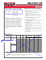
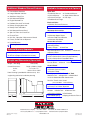
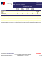
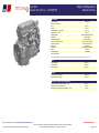
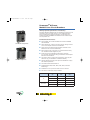
IDLC350-3D
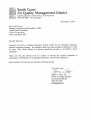
Ratings Range – 60 Hertz Operation
Standby:
kW 200 - 350
kVA 200 - 438
Prime:
kW 185 - 320
kVA 185 - 400
Diesel
Standby and Prime Power Features
4 Heavy-duty industrial diesel engine that meets the latest
EPA emissions levels
4 Brushless synchronous alternators with dynamic
balancing and four pole construction
4 Fully featured microprocessor based controller that’s
easy to use and field programmable for customized
installations
Baldor generators are available in a variety of power ratings
and installation styles to meet the energy needs of the
smallest businesses and the largest manufacturing facilities.
All generator sets are designed to meet the specifications
to ensure the fastest startup and dependable long-term
operation. Rely on Baldor generators to provide the
clean, quiet and environmentally friendly electrical power
when you need it most. Emergency backup, standby,
prime power, peak shaving or for any of your day or night
electrical power needs, you can count on a dependable
Baldor generator to provide the peace of mind and security
you desire.
4 Generator sets are prototype tested and production
tested to ensure easy startup
4 Gen-set accepts rated load in one step
4 Heavy duty construction that’s designed for use in prime
or standby applications
4 Manufactured in a dedicated and secure ISO-9001
certified facility
4 Generator sets are backed by a world wide network of
parts and service centers
4 Optional agency approvals available including UL2200
and NFPA110
4 Optional environmental enclosures available including
weather resistant, sound attenuated, containerized, and
walk-in models
4 Full range of genset accessories and factory installed
options available
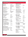
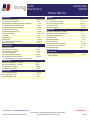
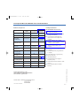
Genset Ratings
150°C Rise
Standby Rating
125°C Rise
Prime Rating
Genset
Model Number
Alternator
Voltage
L-N / L-L
Phase
Hertz
kW / kVA
Amps
kW / kVA
Amps
IDLC350-3D
HCI444E-311
120/208
3
60
325/406
1129
305/381
1059
(1) 120/240
3
60
325/406
978
305/381
918
(1) 120/240
1
60
200/200
833
185/185
771
139/240
3
60
350/438
1054
320/400
963
220/380
3
60
296/370
563
276/345
525
482
We changed the Alternator to
HCI434F - 105 Degree C Rise
277/480
3
60
350/438
527
320/400
HCI444E-17
347/600
3
60
350/438
421
320/400
385
HCI444F-311
120/208
3
60
350/438
1216
320/400
1112
(1) 120/240
3
60
350/438
1054
320/400
963
(1) 120/240
1
60
230/230
958
210/210
875
139/240
3
60
350/438
1054
320/400
963
220/380
3
60
344/430
654
320/400
608
277/480
3
60
350/438
527
320/400
482
347/600
3
60
350/438
421
320/400
385
HCI444F-17
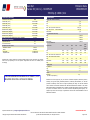
NOTES:
(1) Alternator connections have two circuits available for low voltage.
Available current in each low voltage circuit is equal to high voltage current listed in table.
For ratings and voltages not listed above refer to the Genset Selector.
Standby ratings do not have an overload capability but can be used for the duration of the utility failure per ISO-3046, DIN6271 and BS5514.
Prime (Unlimited Running Time) ratings are continuous per DIN 6271 and ISO-3046 with 10% overload capacity.
Baldor reserves the right to implement specifications or design changes without notice.
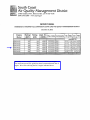
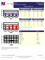
Engine Application Data
Engine Specifications
Manufacturer
Engine Model #
Engine Type
Induction System
Displacement, L (in3) EPA Emissions Level
HP at Rated Speed BHP (kWm)
Rated RPM
Bore and Stroke in(mm) Compression Ratio
Air Filter Type
Governor Type/Model
Governor Manufacturer
Freq Reg NL to FL
Freq Reg Steady State
Engine Lubrication System
Oil Pan Capacity gal(L)
Oil Pan w/Filter
Oil Filter Quantity
Oil Filter Type
Oil Cooler
Recommended Oil
Oil Press psi(kPa)
Engine Cooling System
Genset Max Ambient Temp °F(°C)
Engine Coolant Cap qt(L)
Engine + Radiator System Cap qt(L)
Water Pump Type
Coolant Flow gpm (Lpm)
Heat Rejected to Cooling Water
@ Rated kW; Btu/min (kW)
Heat Rejected to Charge Cooler
@ Rated kW; Btu/min (kW)
Max Restriction of Cooling Air
inH2O(kPa)
Detroit Diesel
6063HV35
4 Cycle, 6 Cylinder
Turbocharged,
Charge Air Cooled
14 (855)
Tier 3
550 (410)
1800
5.24 x 6.61 (133 x 168)
16.0:1
Dry
DDEC V Electronic
Detroit Diesel
Isochronous
+/- 0.25%
8.0 (30.2)
9.5 (35.9)
1
Cartridge
Water Cooled
15W-40
50 (344.7)
122 (50)
24 (22.7)
105 (99.4)
Centrifugal
96 (363.4)
7450 (131)
4900 (86.1)
Engine Electrical System
Charging Alternator Volts dc
Charging Alternator Amps
Grounding Polarity
Starter Motor Volts dc
Battery Recommendations
Battery Volts dc
Min Cold Cranking Amps
Quantity Required
Ventilation Requirements
Cooling Airflow scfm(cmm)
Combustion Airflow cfm(cmm)
Heat Rejected to Ambient
From Engine Btu/min(kW)
From Alternator Btu/min(kW)
Recommended Free Area Intake
Louver Size ft2(m2)
24
70
Negative
24
24
1100
2
21024 (596)
1160 (33)
5024 (88)
2389 (42)
45 (4.18)
Engine Fuel System
Recommended Fuel
#2 Diesel
Fuel Line at Engine
Supply Line Min ID in(mm)
0.5 (13)
Return Line Min ID in(mm)
0.38 (10)
Fuel Pump Type
Engine Driven
Fuel Pump Max Lift ft (m)
6 (2)
Max Flow to Pump gph(Lph)
88.5 (335)
Fuel Filter Secondary Filter
8µm
Secondary Water Separator
Included
Primary Filter
25µm
Primary Water Separator
Included
Fuel Consumption – Standby Rating
100% Load gph(Lph)
27.0 (102.2)
75% Load gph(Lph)
22.1 (83.6)
50% Load gph(Lph)
14.6 (55.3)
25% Load gph(Lph)
7.8 (29.5)
0.5 (0.124)
Engine Exhaust System
Exhaust Manifold Type
Dry
Exhaust Flow @ Rated kW cfm(cmm) 3090 (87)
Exhaust Temp (dry manifold) °F(°C) 963 (503)
Min Back Pressure inH2O(kPa)
0 (0)
Max Back Pressure inH2O(kPa)
40 (10)
Exhaust Outlet Diameter in(mm)
6 (152.4)
Exhaust Outlet Type
O. D. Tube
Fuel Consumption – Prime Rating
100% Load gph(Lph)
25.3 (95.8)
75% Load gph(Lph)
20.1 (76.1)
50% Load gph(Lph)
13.2 (50.0)
25% Load gph(Lph)
7.1 (26.9)
Engine Output Deratings - Standby
Rated Temp
77ºF
Rated Altitude
500 ft
Max Altitude
6,000 ft
Temperature Derate
-1% / 10ºF
Altitude Derate
-1% / 1000 ft
Alternator Specifications
Alternator Type
Exciter Type
Excitation System
Insulation
Material
Standby Temp Rise
Prime Temp Rise
Lead Connection
Stator Pitch
Amortisseur Winding
Bearing
Drive Coupling
Unbalanced Load 4-Pole, Rotating Field
Automatic Voltage Regulator
Brushless
PMG
Std MX341, Opt MX321
PMG
Voltage Regulation
No Load to Full Load
per NEMA MG1
PMG Regulator
+/- 1%, +/- 0.5%
Class H
Load Acceptance
100% of Rating,
150˚C
Changed to 105
Degree C Rise
One Step
125˚C
Subtransient Reactance
12 Lead, Reconnectable
480V, Per Unit
12%
2/3
TIF (1960 Weighting)
<50
Full
Line Harmonics
5% Maximum
Single, Double Shielded
Motor Starting kVA
30% Max Voltage Dip
Flexible Disk
Alt @ 480V SkVA
HCI444E-311 - 1040
20% of Standby Rating
Alt @ 480V SkVA
HCI444F-311 - 1260
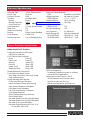
Genset Controller Specifications
Baldor InteliLite NT Features
Large back-lit graphical LCD Display
64x128 pixel resolution
6 LED Genset Status Indicators
Alarm
Red LED
Not In Auto
Red LED
Warning
Yellow LED
Running
Green LED
Ready / Auto
Green LED
Supplying Load
Green LED
Sealed Membrane Panel to IP65
Push Buttons for Simple Control
Start, Stop, Fault Reset, Horn Reset, Mode,
Page, and Enter Keys
Display Metering and Protection
Oil Pressure Warning / Shutdown
High/Low Coolant Temperature Warning
High Coolant Temperature Shutdown
Low Coolant Level Shutdown
Low Fuel Level Warning / Shutdown
Over Speed Protection
Battery Voltage Under/Over Warning
Running Hour Meter
Generator Under/Over Volts Warn/Shutdown
Generator Under/Over Freq Warn/Shutdown
Generator Over Current Shutdown
Generator Output Metering for V1-V3, I1-I3,
Hz, kW, kWh, kVAr, kVAh
NFPA110 Compliance
An optional Remote Annunciator is available
to meet NFPA110 applications
Remote Annunciator Features – RA15
15 LED Indicators with Function Labels
Horn Reset and Lamp Test keys
CAN Bus Connection for up to 600 Feet
Additional Standard Genset Features
Available Accessories and Options
4 Formed Steel Sub-Base
Open Unit
q Industrial Silencer q Residential Silencer
q Critical Silencer
q Super Critical Silencer
q Exhaust Flex Pipe q Rain Cap
q Radiator Duct Flange
Enclosed Units
q Weather Resistant Enclosure
q Sound Attenuated w/Internal Critical Silencer
q ISO Container q Walk-In Enclosure
Alternator Accessories
q PMG Exciter and AVR Upgrade
q Alternator Space Heater
q Exciter Field Circuit Breaker
q Alternator Drip Shield
Genset Accessories
q Voltage Adjust Potentiometer
q Starting Battery
Battery Charger
q Auto/Float
Auto/Float Equalize Timer q Manual q Automatic
q Battery Heater
q Engine Coolant Heater
q Oil & Coolant Drain Valves (Engine/Radiator)
q Oil & Coolant Drain Extended to Base
Main Output Breaker q Wall Mount q Unit Mount
Transfer Switch q Manual q Automatic
Control Panel
q Remote Annunciator
q Remote Communications
q Remote E-Stop
Fuel System and Sub-Base Fuel Tank
Sub-Base Tank q Single Wall q Double Wall
q UL142 Double Wall with Containment
Tank Run Time @ 100% Load
q 12-16 Hours q 24-36 Hours
q Flex Fuel Line
q Primary Fuel / Water Separator
Vibration Isolators
Location q Under Tank q Between Tank
q Elastomer Isolator q Pad Isolator
q Standard Spring q Spring for Seismic Zone 4
4 Integral Vibration Isolation
4 Sub-Base Lifting Eyes
4 Unit Mounted Radiator
4 Engine Mounted Fan
4 Radiator Core and Fan Guards
4 Battery Charging Alternator
4 Battery Rack and Cables
4 Unit Mounted Control Panel
4 Spin-On Filters for Oil and Fuel
4 Enamel Finish
4 One Set - Operation / Maintenance Manual
4 Factory Tested Prior to Shipment
4 Limited Warranty
These options are included
Optional Agency Approvals
q UL2200 (Review Option Availability)
q NFPA110 (Request Remote Annunciator)
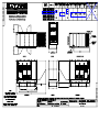
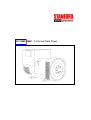
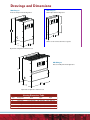
Weight and Dimensions (Open Unit)
Weight – Wet lb(kg)
Overall Dimensions inches
mm
7449 (2895)
Length x Width x Height
137 x 60 x 75
3480 x 1524 x 1905
Note: Drawing is provided for reference only. Use
engineering outline for installation planning
© Baldor Electric Company
FM24703D
WORLD HEADQUARTERS
Baldor Electric Company • P. O. Box 2400 • Fort Smith, AR 72902-2400 U.S.A.
Phone (479) 646-4711 • Fax (479) 648-5792 • International Fax (479) 648-5895
www.baldor.com
Printed in U.S.A.
3/08 CMB 2000
COMPLY WITH APPLICABLE STATE AND
LOCAL GOVERNMENT NOISE LEVEL 2 PER
63213D,1.5,I
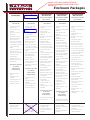
Enclosure Packages
Sound Attenuated
HPE Level One
Specification Available
Upon Request
Sound Attenuated
HPE Level Two
Specification Available
Upon Request
Sound Attenuated
HPE Level Three
Specification Available
Upon Request
Applicable to all models
above 250 kW
Applicable to all models
above 900 kW
Applicable to all models
above 500 kW
Applicable to all models
• 14 gauge steel ASTM
A569, #4 finish
• Optional 0.080, 5052
Aluminum
• Interior walls lined with
acoustical foam
• Modular construction-full
flexibility
• Powder paint system
• Weather Resistant drip
proof construction
• Heavy duty door gaskets
• 2 or 4 side access doors
• Heavy duty latch assembly
• Heavy duty lockable
handle
• Heavy duty stainless steel
hinge with brass pin
• Fixed intake louvers
• Structural base
• Radiator cap access
• External radiator discharge
hood with screen
• Rain gutter over all doors
and openings
• 15 dbA noise reduction at
3 meters
• 14 gauge steel ASTM
A569, #4 finish
• Optional 0.080, 5052
Aluminum
• Modular construction-full
flexibility
• Powder paint system
• Weather Resistant
drip proof construction
• Heavy duty door gaskets
• 2 or 4 side access doors
• Heavy duty latch assembly
• Heavy duty lockable
handle
• Heavy duty stainless steel
hinge with brass pin
• Pre-hung door assemblies
• Sound deadening interior
wall construction
• Interior surfaces lined with
perforated mill finish
aluminum
• Acoustic Intake louversfixed, aluminum
• Internal discharge hood
• Radiator cap access
• Mounting to frame or tank
• Exhaust system required –
not included **
• Rain gutter over all doors
and openings
• 3" Wall construction
• Isolators required - not
included
• Shipping supports – Field
adjustable
• 25 dbA noise reduction at
3 meters
• 14 gauge steel ASTM A569,
#4 finish
• Optional 0.080, 5052
Aluminum
• Modular construction-full
flexibility
• Powder paint system
• Weather Resistant
drip proof construction
• Heavy duty door gaskets
• 2 or 4 side access doors
• Heavy duty latch assembly
• Heavy duty lockable handle
• Heavy duty stainless steel
hinge with brass pin
• Pre-hung door assemblies
• Sound deadening interior
wall construction
• Acoustic composite barrier
material
• Interior surfaces lined with
perforated mill finish
aluminum
• Insulated Intake air hoods
• Acoustic Intake louversfixed, aluminum
• Internal discharge hood
• Radiator cap access
• Mounting to frame or tank
• Exhaust system required –
not included **
• Rain gutter over all doors
and openings
• 3" Wall construction
• Isolators required - not
included
• Shipping supports – Field
adjustable
• 40 dbA noise reduction at 3
meters
Standard/Basic
Basic Attenuation
Applicable to all models
above 250 kW
• 14 gauge steel ASTM
A569, #4 finish
• Optional 0.080, 5052
Aluminum
• Modular construction –
full flexibility
• Powder paint system
• Weather Resistant drip
proof construction
• Heavy duty door gaskets
• 2 or 4 side access doors
• Heavy duty latch assembly
• Heavy duty lockable
handle
• Heavy duty stainless steel
hinge with brass pin
• Pre-hung door assemblies
• Fixed intake louvers
• Structural base
• Radiator cap access
• Rain gutter over all doors
and openings
Applicable to all models
20 - 250 kW
Same as above
except following:
• Doors are lift-off not
hinged
• Standard duty latch
assembly
• Punched intake screen
• Formed steel base
• Mounting to Gen-set
Applicable to all models
20 - 250 kW
Same as above
except following:
• Doors are lift-off not
hinged
• Standard duty latch
assembly
• Punched intake screen
• Formed steel base
• Mounting to Gen-set
Applicable to all models
30 - 825 kW
Same as above
except following:
• External radiator discharge
hood with screen
* Internally mounted silencer
may affect ambient
performance and
enclosure dimensions
* Internally mounted silencer
may affect ambient
performance and
enclosure dimensions
** Basic noise reduction dbA
level not available
* Internally mounted silencer
may affect ambient
performance and
enclosure dimensions
** Must be Critical Grade at
minimum
Applicable to all models
30 - 450 kW
Same as above
except following:
• 14 gauge steel ASTM A569,
#4 finish
• Optional 0.080, 5052
Aluminum
• Modular construction-full
flexibility
• Powder paint system
• Weather Resistant
drip proof construction
• Heavy duty door gaskets
• 2 or 4 side access doors
• Heavy duty latch assembly
• Heavy duty lockable handle
• Heavy duty stainless steel
hinge with brass pin
• Pre-hung door assemblies
• Fixed intake louvers
• Radiator cap access
• Mounting to frame or tank
• 6" Wall construction
• Sound deadening interior
wall construction
• Acoustic composite barrier
material
• Interior surfaces lined with
perforated mill finish
aluminum
• Intake air attenuator
• Interior vertical discharge
with attenuator.
• Exhaust system required –
not included **
• Rain gutter over all doors
and openings
• Isolators required - not
included
• Shipping supports – Field
adjustable
• External Insulated radiator
discharge hood with screen
* Internally mounted silencer
may affect ambient
performance and enclosure
dimensions
** Must be Critical Grade at
minimum
* Internally mounted silencer
may affect ambient
performance and enclosure
dimensions
** Must be Super Critical
Grade at minimum
Paint Specification - applicable to all Enclosures
(Detailed paint specification follows on page 2 of Appendix F)
Powder Paint System consisting of the following:
Almond is our standard color. Please
notify PMT before final approval
1. Three stage wash system with Phosphate treatment
2. Application of sealant
3. Electrostatically applied enamel based powder paint 1.5 to 2.5 mil thickness
4. Baked at 400o for 15 mintues
5. Almond is our standard color
COORDINATE FINAL COLOR WITH
OWNER PER 263213D,2.12,A
(other colors available see pricing schedule for cost)
Insulation Specification
(applicable to Level 1, 2 & 3 only)
Sound Deadening Material specifications:
1. Material is an inorganic glass fiber pre-formed into boards and bonded by a thermosetting resin
2. Density of materials is a 3.0 PCF (48 kg/cm3)
3. Thickness of materials is 3" on Level 1 & 2 Enclosures. Thickness of materials is 6" on Level 3 Enclosures
4. Surface burning characteristics meet the requirements of NFPA 90A & 90B
5. Moisture absorption: (ASTM C553) less than 5% by weight when exposed to air at 120˚F (49˚C) and 95% humidity for 96 hours
6. Shrinkage: (ASTM C356) will exhibit less than 0.3% linear shrinkage
These specifications are subject to change without notice.
Copyright Baldor Generators.
This information is confidential and proprietary to Baldor Generators
* PROVIDE ENGINE INFORMATION SIMILAR TO NATURAL GAS SUBMITTAL
* PROVIDE EMISSIONS INFORMATION SIMILAR TO NATURAL GAS SUBMITTAL
3815 Oregon Street • Oshkosh, WI 54902 • 1-800-872-7697 • Phone (920) 236-4200 • Fax (920) 236-4219
909 Perkins Drive • Mukwonago, WI 53149 • Phone (262) 363-1555 • Fax (262) 363-1556
World Headquarters
Baldor Electric Company • P.O. Box 2400 • Fort Smith, AR 72902-2400 U.S.A.
Phone (479) 646-4711 • Fax (479) 648-5792 • International Fax (479) 648-5895
www.baldor.com
© Baldor Electric Company
Printed in the U.S.A.
FM2491E
5/05 FARR 5000
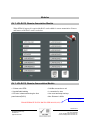
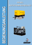
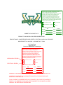
This is the certification information for the Detroit Diesel Engine.
The certificate meets EPA guidelines based on manufactured date of
engine. We will be utilizing the 2011 engine indicated above.
5
4
4
-% ?$+% A # -%-'3E'&
&&% G $)%% "
!
$%
(&
&%
,&
$%%
&&
$')
(,&
+$'
&&%
"#
%&'(
%'*+
%',%
%'-(
%'+'
!
$%
(&
&%
,&
$%%
$$%
!
$%
(&
&%
,&
$%%
&&
$')
(,&
+$'
&&%
"#
%&'(
%'*+
%',%
%'-(
%'+'
%-F%+=)$+&
+)
$$*
('*
'&)
+,,
&(&
"#
%&&$
%+%*
%')$
%',(
%'-%
%'-$
!
$%
(&
&%
,&
$%%
+)
$$*
(')
'&+,&
"#
%&&$
%+%*
%')$
%',(
%'-%
.
/("#%! .
0
.
. 2 2 0
.
4
5
6
7
0
8
:; 2< = 3
6
7
9 ! "#$$%
,, 1
'% 3
(* 3
$%% 1
%)',$%% 1
$% 3(9
$& 3(9
(%&%% 2"
#
%$ ">
-** " ?@4A
,&% " ?@4A
0B
C &''()*+
. C (% :
(%%,
,-.-/0.!1 .2
.
< =.@ :;
D $***#(%%, =.@ 0 $ *
5
4
4
-% ?$+% A # -%-'3E'&
&&% G $)%% "
4 -% 3H # ',% <I
-% 3H # '(% <I
-% 3H # ',% <I
.
%-F%+=)$+&
-% 3H # '(% <I
) 1)
4
=; =; 4
8
8
4
. 0
4
. 3 0
4
:
E :
&&%
$)%%
&&%
$)%%
#
#
4 0
@
:
E :
&&%
$)%%
+,,
$)%%
#
#
:
E :
&&%
$)%%
&&%
$)%%
#
#
8 .
:
E :
&&%
$)%%
+,&
$)%%
#
#
#
"
"
"
"
#
)' :
8
:
3
8
J
:
3
8
J
8
3
8
J
(+
*,+&%
+*%%
'*&%
(+
*,$&%
+,%%
'*&%
(+
*,+&%
+*%%
'*&%
(+
*,$&%
+,%%
'*&%
B ?@4A
" ?@4A
2"
2"
2"
'%*%
*-'
()'(
*%)
'%*%
*-'
()'(
*%)
>"
1
:@0 F'
:@0
#
#
#
#
#
$))&
(,%
$&%
:@0 F'
:@0
#
#
#
#
#
$,$&
(+&
#
:@0 F'
:@0
#
#
#
#
#
$))&
(,%
$&%
:@0 F'
:@0
#
#
#
#
#
$,%)
(++
#
#
#
"
" ?@4A
"
" ?@4A
"
" ?@4A
2"
$$-%
-(
'-(
$$%)
&+
'+(
$$-%
-(
'-(
$$%)
&+
'+(
>"
3
1
!34 :; 8
?
A
:; .
5) 0J
0J
4
0J
. 3
8
?A
8
?
A
4 8
?A
4 8
?
A
?A
?
A
3
8
J
6 :
8
?
A
0<
= .
9
.
0B
C &''()*+
. C (% :
(%%,
,-.-/0.!1 .2
.
< =.@ :;
D $***#(%%, =.@ 0 ( *
5
4
4
-% ?$+% A # -%-'3E'&
&&% G $)%% "
.
%-F%+=)$+&
4 -% 3H # ',% <I
-% 3H # '(% <I
-% 3H # ',% <I
-% 3H # '(% <I
#
#
%$*
%$%
#
#
%$,
%%*
#
#
%$*
%$%
#
#
%$,
%%*
" ?@4A
"K
"
B" ?@4A
#
()'
$-%
#
$*)+
5.&& I
#
(+$-%
#
$*)+
5.&& I
#
()'
$-%
#
$*)+
5.&& I
#
(+&
$-%
#
$*)+
5.&& I
"K
C$
"
#
+ 9 8
9 9 ?A
9 ?
A
) 67
2<
=
:
?2=:A
8
3
=
4
.
0B
C &''()*+
. C (% :
(%%,
,-.-/0.!1 .2
.
< =.@ :;
D $***#(%%, =.@ 0 ' *
5
4
4
-% ?$+% A
)' 0 -%-'3E'&
&&% G $)%% "
5) = 8
:
=; 9 .
:
=; :
I
?:;
= I
0
?8 I# 8A
= I
0
? 8A
=; I
4 3
=; :;
8
:
= :
8
= =; .
= =; 4
?:;
A
= . .< .
A
)-+
($%
#
%%
%%
($,
&'
'%
$%
'%
*%
,)
$-%
" ?@4A
1
"K
"K
"K
"K
"K
" ?@4A
!
"K
"K
1
#
*%%
$)%%
#
(%%$
$%%%
#
47 =; 8 # <
=; # . 2
=; 0
# . 2
=; 4< # . 2
=; E
8
?LA
=; 4 2
=
8
2<
?LA .
9:= =; 0
.
=; 4 4
=; 4 4
8
4H
=; 4
4H
$+%
-%
$((
(&
&
1
3
3
6 =; 0<
= .
=; . 0
.
8
=; 4
. =; <
=; 0<
= =; 0<
= .
=; 0<
8
=; 0<
8
8
0<
# 4
8
0<
# +&
'%
+
'
#
$&$
$(
(%
-%
#
1
1
1
3
3(9
3
3 (9
3(9
+ =; 9 :
9 9
8
#
0
# 3(9
!)++) =; 8
4
=; 8
4
8
2
# $( E
8
2
# (+ E
# $( E 4
# (+ E 4
4
4
%%%$( M
%%%( M
$),&
*&%
!34 =; :; 4
2< 8
:; # 4
8
:; # '% 3
&% +% 0B
C &''()*+
. C (% :
(%%,
,-.-/0.!1 .2
.
< =.@ :;
D $***#(%%, =.@ 0 + *
5
4
4
-% ?$+% A # -%-'3E'&
&&% G $)%% "
7+ ! 1
? I A
@4 F ?.
$A
@4 F ?.
(A
@4 F ?.
'A
@4 F ?.
+A
:@89 F ?4
0A
:@89 F ?4
00A
:@89 F ?4
000A
:@89 F ?4
0EA
4 N =
?4 N=A
&&'+
F F F F F F F &)+ O
F
.# 4 N= 0
# F
# 4
# 0
# :; F
F
+'*$')
%$ 8 (%%&
%$ 8 (%%-
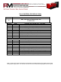
FUEL REQUIREMENTS BEGINNING OCTOBER 1, 2010
REQUIRES #2 ULTRA LOW SULFUR DIESEL.
4
#
: 4
F9;
9
3
49( # &! 49( # %15 !
$ : 4
F9;
9
3
( # :
(%%,
#
#
#
+(,
"
"
"
"
12.8 "
# "
#
#
#
#
"P
"P
"P
"P
:
$%!
(&!
&%!
,&!
$%%!
9
3
49( # %&! 49( # %015! F9;
9 =
<
4<
2 F
G < .B
4
?# #A
(*$
,''
--+
($$
'&&
$('
"
$,(
$*)
('$
$'(
$,)
''*
(-$
$(&
+(,
1.3
3.2
6.4
9.6
12.8
$%*
$)-
(*%
'%%
+$%
+,+
())
)',
'))
$--&
E
"P
%),
%$'
#
#
%$+
(+*
# !
# !
# !
%+
#
: B .
.
@
4
F 2
4 @4 : +% 8 )* ? : F
0#@
F #0 :
A .
@4 : 4 @4
: 0B
C &''()*+
. C (% :
: %-F%+=)$+&
,-.-/0.!1 .2
.
< =.@ :;
D $***#(%%, =.@ 0 & *
5
4
4
-% ?$+% A # -%-'3E'&
&&% G $)%% "
F
4
%-F%+=)$+&
<= >
+
')9
<= >
+
/:9
<= >
#
#
#
#
#
#
#
#
#
#
#
#
#
#
#
#
#
#
#
#
#
#
#
#
#
#
#
#
#
#
#
#
#
#
#
#
#
#
#
#
#
#
#
#
#
#
#
#
#
#
#
#
#
#
#
#
#
#
#
#
#
#
#
#
#
#
#
#
#
#
#
#
#
#
#
#
#
#
#
#
#
#
#
#
#
#
#
#
#
#
#
#
#
#
#
#
#
#
#
#
#
#
#
#
#
#
#
#
.
.
.
.
58+
9
7+9
!349
<= >
+%
)%
$%%
$(&
$-%
(%%
(&%
'$&
+%%
&%%
-'%
)%%
$%%%
$(&%
$-%%
(%%%
(&%%
'$&%
+%%%
&%%%
-'%%
)%%%
$%%%%
$(&%%
$-%%%
(%%%%
.
#
-(%
,$%
,&%
)'%
)%%
,*%
)'%
)&%
),%
*$%
*-%
*)%
*&%
*-%
*-%
*&%
*+%
)*%
)-%
)+%
))%
,-%
,'%
,$%
#
$%&(
.
+ ;+)9
<= >
/)+
.
.
4
0B
C &''()*+
. C (% :
(%%,
,-.-/0.!1 .2
.
< =.@ :;
D $***#(%%, =.@ 0 - *
5
4
4
-% ?$+% A
47
@ 5 F
.
=
4
# O
4
# 47
%-Q%$2-%**
5
#
0 2 < ?4: $&$'A
5 0J
R :;C .
0<
C 5
47 <'
.
=
=
:
6=:7
=
O 6=O7
J
6
7
.#
.
?4
<
H
A
$+)- (&&* ')% K
+' 0
.
=
S0S#
# 4: +$+%
+' 0 &
.
=
#
#
+' 0 <'
.
N 6
J7
=
# 2
=
# @
2
=
:
6=:7
=
O 6=O7
J
6
7
=
-%-'3E'&
#
(
.
?
#<
H
A
.
?
#<
H
A
$,%& ''+- &,% K
.
=
4
# O
.
2
9
#
# 4: $&+)
0 47 ? <'
.
N 6
J7
=
# 2
=
# @
2
=
:
6=:7
=
O 6=O7
J
6
7
#
(
.
?
#<
H
A
.
?
#<
H
A
$&+, +*($ ,-$ K
47 /4 <'
.
N
=
:
6=:7
=
O 6=O7
J
6
7
#
#
# # # K
) <)+
@ 5 F
.
=
%-%$ -%+'
0
<
) @ 5 F
.
=
=
%-%( -%'+
9
#
+ #
) @ 5 F
.
=
0B
C &''()*+
. C (% :
(%%,
%-%$ -%+'
I
,-.-/0.!1 .2
.
< =.@ :;
D $***#(%%, =.@ 0 , *
5
4
4
-% ?$+% A
!34 ;):
.
=
# 3
=
# 4
9
=
.
N 6
7
N 6 7
F<
#
#
9
<
8
(
$
!34 ;): 6
.
=
8
F<
#
# 5='&&%
6 ;):
.
=
# 3
=
# 4
9
=
.
N 6
7
N 6 7
=
-%-'3E'&
0#
#
9
<
8
(
$
6 ;): 6
.
=
.
=
# =
# 4<
.
=
I T
#
#
<'
.
=
9
#
2H
# 0'9 &
. 8
4
8
N 6
7
T
# T
# #
#
0'9 .)
.
N 6
7
;
$
2 8
0#
# 5=,-$'&
0B
C &''()*+
. C (% :
#
4
9# < <
(%%,
,-.-/0.!1 .2
.
< =.@ :;
D $***#(%%, =.@ 0 ) *
5
4
4
-% ?$+% A # -%-'3E'&
:
4
1+&
=
F
F
2
4<
# # 4
4
:
4
:
.
E
4
-%-'3E'&
&(+ --$ $+( >
)&& >
F .
0J
## : E :
0
:
9
:
<
%$ OF (%%&
#
. &% -% 3H
9
9
I
9
3
&,(% '*-' &%%, '4
;
I
;
I
I
(&&$ (-,* 7 @:
7 1
!'
8
2<C ;#;
<C #;
8 <C H#;
0B
C &''()*+
. C (% :
(%%,
(('% ,&( $'( ,-.-/0.!1 .2
.
< =.@ :;
D $***#(%%, =.@ 0 * *
HCI 434F/444F - Technical Data Sheet
HCI434F/444F
SPECIFICATIONS & OPTIONS
STANDARDS
Newage Stamford industrial generators meet the
requirements of BS EN 60034 and the relevant section
of other international standards such as BS5000, VDE
0530, NEMA MG1-32, IEC34, CSA C22.2-100, AS1359.
Other standards and certifications can be considered on
request.
VOLTAGE REGULATORS
SX440 AVR - STANDARD
With this self-excited system the main stator provides
power via the Automatic Voltage Regulator (AVR) to the
exciter stator. The high efficiency semi-conductors of
the AVR ensure positive build-up from initial low levels
of residual voltage.
The exciter rotor output is fed to the main rotor through
a three-phase full-wave bridge rectifier. The rectifier is
protected by a surge suppressor against surges
caused, for example, by short circuit or out-of-phase
paralleling.
The SX440 will support a range of electronic
accessories, including a 'droop' Current Transformer
(CT) to permit parallel operation with other ac
generators.
If 3-phase sensing is required with the self-excited
system, the SX421 AVR must be used.
SX421 AVR
This AVR also operates in a self-excited system. It
combines all the features of the SX440 with,
additionally, three-phase rms sensing for improved
regulation and performance. Over voltage protection is
provided via a separate circuit breaker. An engine relief
load acceptance feature is built in as standard.
MX341 AVR
This sophisticated AVR is incorporated into the
Stamford Permanent Magnet Generator (PMG) control
system.
The PMG provides power via the AVR to the main
exciter, giving a source of constant excitation power
independent of generator output. The main exciter
output is then fed to the main rotor, through a full wave
bridge, protected by a surge suppressor. The AVR has
in-built protection against sustained over-excitation,
caused by internal or external faults. This de-excites
the machine after a minimum of 5 seconds.
An engine relief load acceptance feature can enable full
load to be applied to the generator in a single step.
If three-phase sensing is required with the PMG system
the MX321 AVR must be used.
We recommend three-phase sensing for applications
with greatly unbalanced or highly non-linear loads.
MX321 AVR
The most sophisticated of all our AVRs combines all the
features of the MX341 with, additionally, three-phase
rms sensing, for improved regulation and performance.
Over voltage protection is built-in and short circuit
current level adjustments is an optional facility.
WINDINGS & ELECTRICAL PERFORMANCE
All generator stators are wound to 2/3 pitch. This
eliminates triplen (3rd, 9th, 15th …) harmonics on the
voltage waveform and is found to be the optimum
design for trouble-free supply of non-linear loads. The
2/3 pitch design avoids excessive neutral currents
sometimes seen with higher winding pitches, when in
parallel with the mains. A fully connected damper
winding reduces oscillations during paralleling. This
winding, with the 2/3 pitch and carefully selected pole
and tooth designs, ensures very low waveform
distortion.
TERMINALS & TERMINAL BOX
Standard generators are 3-phase reconnectable with 12
ends brought out to the terminals, which are mounted
on a cover at the non-drive end of the generator. A
sheet steel terminal box contains the AVR and provides
ample space for the customers' wiring and gland
arrangements. It has removable panels for easy
access.
SHAFT & KEYS
All generator rotors are dynamically balanced to better
than BS6861:Part 1 Grade 2.5 for minimum vibration in
operation. Two bearing generators are balanced with a
half key.
INSULATION/IMPREGNATION
The insulation system is class 'H'.
All wound components are impregnated with materials
and processes designed specifically to provide the high
build required for static windings and the high
mechanical strength required for rotating components.
QUALITY ASSURANCE
Generators are manufactured using production
procedures having a quality assurance level to BS EN
ISO 9001.
The stated voltage regulation may not be maintained in
the presence of certain radio transmitted signals. Any
change in performance will fall within the limits of
Criteria 'B' of EN 61000-6-2:2001. At no time will the
steady-state voltage regulation exceed 2%.
NB Continuous development of our products entitles us
to change specification details without notice, therefore
they must not be regarded as binding.
Front cover drawing typical of product range.
2
HCI434F/444F
WINDING 311
CONTROL SYSTEM
SEPARATELY EXCITED BY P.M.G.
A.V.R.
MX321
MX341
VOLTAGE REGULATION
± 0.5 %
± 1.0 %
With 4% ENGINE GOVERNING
SUSTAINED SHORT CIRCUIT
REFER TO SHORT CIRCUIT DECREMENT CURVES (page 7)
CONTROL SYSTEM
SELF EXCITED
A.V.R.
SX440
SX421
VOLTAGE REGULATION
± 1.0 %
± 0.5 %
SUSTAINED SHORT CIRCUIT
With 4% ENGINE GOVERNING
WILL NOT SUSTAIN A SHORT CIRCUIT
INSULATION SYSTEM
CLASS H
IP23
PROTECTION
0.8
RATED POWER FACTOR
DOUBLE LAYER LAP
STATOR WINDING
TWO THIRDS
WINDING PITCH
12
WINDING LEADS
0.0073 Ohms PER PHASE AT 22°C SERIES STAR CONNECTED
STATOR WDG. RESISTANCE
1.37 Ohms at 22°C
ROTOR WDG. RESISTANCE
R.F.I. SUPPRESSION
BS EN 61000-6-2 & BS EN 61000-6-4,VDE 0875G, VDE 0875N. refer to factory for others
WAVEFORM DISTORTION
NO LOAD < 1.5% NON-DISTORTING BALANCED LINEAR LOAD < 5.0%
2250 Rev/Min
MAXIMUM OVERSPEED
BALL. 6317 (ISO)
BEARING DRIVE END
BALL. 6314 (ISO)
BEARING NON-DRIVE END
1 BEARING
2 BEARING
WEIGHT COMP. GENERATOR
1160 kg
1160 kg
WEIGHT WOUND STATOR
535 kg
535 kg
WEIGHT WOUND ROTOR
463 kg
440 kg
5.4292 kgm2
1775 kg
5.2304 kgm2
1780 kg
155 x 87 x 107(cm)
156 x 87 x 107(cm)
WR² INERTIA
SHIPPING WEIGHTS in a crate
PACKING CRATE SIZE
TELEPHONE INTERFERENCE
50 Hz
60 Hz
THF<2%
TIF<50
0.486 m³/sec 1030 cfm
COOLING AIR
0.580 m³/sec 1240 cfm
VOLTAGE SERIES STAR
380/220
400/231
415/240
440/254
416/240
440/254
460/266
480/277
VOLTAGE PARALLEL STAR
190/110
200/115
208/120
220/127
208/120
220/127
230/133
240/138
VOLTAGE SERIES DELTA
kVA BASE RATING FOR REACTANCE
VALUES
Xd DIR. AXIS SYNCHRONOUS
220/110
230/115
240/120
254/127
240/120
254/127
266/133
277/138
380
380
380
380
444
456
463
475
2.59
2.34
2.17
1.93
3.21
2.95
2.74
2.58
X'd DIR. AXIS TRANSIENT
0.17
0.15
0.14
0.12
0.18
0.17
0.15
0.14
X''d DIR. AXIS SUBTRANSIENT
0.12
0.11
0.10
0.09
0.13
0.12
0.11
0.10
Xq QUAD. AXIS REACTANCE
2.23
2.01
1.87
1.66
2.84
2.61
2.42
2.28
X''q QUAD. AXIS SUBTRANSIENT
0.30
0.27
0.25
0.22
0.42
0.39
0.36
0.34
XL LEAKAGE REACTANCE
0.06
0.05
0.05
0.04
0.07
0.06
0.06
0.06
X2 NEGATIVE SEQUENCE
0.21
0.19
0.18
0.16
0.28
0.26
0.24
0.22
X0 ZERO SEQUENCE
0.08
0.08
0.07
0.06
0.10
0.09
0.09
0.08
REACTANCES ARE SATURATED
T'd TRANSIENT TIME CONST.
T''d SUB-TRANSTIME CONST.
T'do O.C. FIELD TIME CONST.
Ta ARMATURE TIME CONST.
SHORT CIRCUIT RATIO
VALUES ARE PER UNIT AT RATING AND VOLTAGE INDICATED
0.08s
0.019s
1.7s
0.018s
1/Xd
3
HCI434F/444F
Winding 311
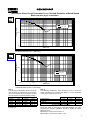
THREE PHASE EFFICIENCY CURVES
60
Hz
5
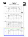
HCI434F/444F
Winding 311
Locked Rotor Motor Starting Curve
50
Hz
MX
346V
30
380V 400V
415V
SX
440V
380V
400V
415V
440V
25
P E R C E N T T R A N S IE N T V O L T A G E D I P .
25
P E R C E N T T R A N S IE N T V O L T A G E D IP .
346V
30
20
20
15
15
10
10
5
5
0
0
0
200
400
600
800
1000
1200
1400
0
LOCKED ROTOR kVA
100
200
300
400
500
LOCKED ROTOR kVA
600
700
800
900
460V
480V
1000
60
Hz
MX
380V
416V
440V
460V
480V
380V
30
25
25
20
20
P E R C E N T T R A N S IE N T V O L T A G E D IP .
P E R C E N T T R A N S IE N T V O L T A G E D IP .
30
SX
15
10
5
416V
440V
15
10
5
0
0
0
200
400
600
800
LOCKED ROTOR kVA
6
1000
1200
1400
0
200
400
600
LOCKED ROTOR kVA
800
1000
1200
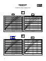
HCI434F/444F
Three-phase Short Circuit Decrement Curve. No-load Excitation at Rated Speed
Based on star (wye) connection.
50
Hz
10000
SYMMETRICAL
CURRENT (Amps)
ASYMMETRICAL
1000
100
0.001
0.01
0.1
TIME (secs)
1
10
Sustained Short Circuit = 1,750 Amps
60
Hz
CURRENT (Amps)
10000
1000
SYMMETRICAL
ASYMMETRICAL
100
0.001
0.01
0.1
TIME (secs)
1
10
Sustained Short Circuit = 2,000 Amps
Note 1
The following multiplication factors should be
used to adjust the values from curve between
time 0.001 seconds and the minimum current
point in respect of nominal operating voltage :
50Hz
Voltage
380v
400v
415v
440v
Factor
X 1.00
X 1.05
X 1.09
X 1.16
60Hz
Voltage
416v
440v
460v
480v
Note 2
The following multiplication factor should be used to convert the
values calculated in accordance with NOTE 1 to those applicable
to the various types of short circuit :
3-phase
Factor
X 1.00
X 1.06
X 1.10
X 1.15
The sustained current value is constant irrespective
of voltage level
2-phase L-L 1-phase L-N
x 1.00
x 0.87
x 1.30
Instantaneous
Minimum
x 1.00
x 1.80
x 3.20
Sustained
x 1.00
x 1.50
x 2.50
Max. sustained duration
10 sec.
5 sec.
2 sec.
All other times are unchanged
Note 3
Curves are drawn for Star (Wye) connected machines. For other
connection the following multipliers should be applied to current
values as shown :
Parallel Star = Curve current value X 2
Series Delta = Curve current value X 1.732
7
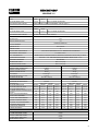
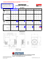
PROVIDE TEMPERATURE RISE OF 105 DEGREE C STAND-BY RATING
PER SPECIFICATION SECTION 26 3213D, 2.9, D.
Continuous Duty is rated for an
extended outage and Standby is
rated for a day or two outage. So
the Continuous duty is a better
rating.
Hz
60
Hz
Winding 311 / 0.8 Power Factor
RATINGS
Cont. F - 105/40°C
Class - Temp Rise
50
HCI434F/444F
Cont. H - 125/40°C
Standby - 150/40°C
Standby - 163/27°C
Series Star (V)
380
400
415
440
380
400
415
440
380
400
415
440
380
400
415
440
Parallel Star (V)
190
200
208
220
190
200
208
220
190
200
208
220
190
200
208
220
Series Delta (V)
220
230
240
254
220
230
240
254
220
230
240
254
220
230
240
254
kVA
350
350
350
350
380
380
380
380
390
390
390
390
404
404
404
404
kW
280
280
280
280
304
304
304
304
312
312
312
312
323
323
323
323
Efficiency (%) 93.8
94.0
94.1
94.2
93.4
93.7
93.8
94.0
93.3
93.5
93.7
93.9
93.1
93.4
93.5
93.7
kW Input
299
298
298
297
325
324
324
323
334
334
333
332
347
346
346
345
Series Star (V)
416
440
460
480
416
440
460
480
416
440
460
480
416
440
460
480
Parallel Star (V)
208
220
230
240
208
220
230
240
208
220
230
240
208
220
230
240
Delta (V)
240
254
266
277
240
254
266
277
240
254
266
277
240
254
266
277
kVA
405
420
425
438
444
456
463
475
475
483
488
500
488
500
506
519
kW
324
336
340
350
355
365
370
380
380
386
390
400
390
400
405
415
Efficiency (%) 93.9
94.0
94.1
94.1
93.5
93.7
93.8
93.9
93.2
93.4
93.6
93.7
93.0
93.2
93.4
93.5
357
361
372
380
389
395
405
408
414
417
427
420
429
433
444
kW Input
345
DIMENSIONS
© 2002 Newage International Limited.
Reprinted with permission of N.I. only.
Printed in England.
PO Box 17 • Barnack Road • Stamford • Lincolnshire • PE9 2NB
Tel: 00 44 (0)1780 484000 • Fax: 00 44 (0)1780 484100
Website: www.newage-avkseg.com
TD_HCI4F.GB_08.02_01_GB
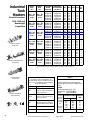
Industrial
Tank
Heaters
Ambient
Above
-20° F
Ambient
Below
-20° F
(Conduit Connection)
350 — 500
Cubic Inch
or Less
200 — 300
Cubic Inch
or Less
1500 - 5000 watt
Weathertight
Single Phase
500 — 600
Cubic Inch
or Less
300 — 400
Cubic Inch
or Less
600 — 800
Cubic Inch
or Less
400 — 500
Cubic Inch
or Less
800 — 1000
Cubic Inch
or Less
500 — 600
Cubic Inch
or Less
1000 — 1350
Cubic Inch
or Less
600 — 800
Cubic Inch
or Less
CB Model without
thermostat.
CB Model assembled with
thermostat.
1350 — 1650 800 — 1000
Cubic Inch
Cubic Inch
or Less
or Less
Model Number
without
Thermostat
CB115100-000
CB115800-000
CB115200-000
CB115700-000
CB115300-000
CB115400-000
CB120100-000
CB120800-000
CB120200-000
CB120300-000
CB120400-000
CB125100-000
CB125800-000
CB125200-000
CB125700-000
CB125300-000
CB125400-000
CL130100-100
CL130800-100
CL130200-100
CL130700-100
CL130300-100
CL130400-100
CL140800-100
CL140200-100
CL140700-100
CL140300-100
CL140400-100
CL150800-100
CL150200-100
CL150700-100
CL150300-100
CL150400-100
Model Number
with Thermostat
(see chart 1)
CB1151XX-000
CB1158XX-000
CB1152XX-000
CB1157XX-000
CB1153XX-000
CB1154XX-000
CB1201XX-000
CB1208XX-000
CB1202XX-000
CB1203XX-000
CB1204XX-000
CB1251XX-000
CB1258XX-000
CB1252XX-000
CB1257XX-000
CB1253XX-000
CB1254XX-000
CL1301XX-100
CL1308XX-100
CL1302XX-100
CL1307XX-100
CL1303XX-100
CL1304XX-100
CL1408XX-100
CL1402XX-100
CL1407XX-100
CL1403XX-100
CL1404XX-100
CL1508XX-100
CL1502XX-100
CL1507XX-100
CL1503XX-100
CL1504XX-100
Volts Watts Phase Amps Fig.*
No.
120
208
240
277
380
480
120
208
240
380
480
120
208
240
277
380
480
120
208
240
277
380
480
208
240
277
380
480
208
240
277
380
480
1500
1500
1500
1500
1500
1500
2000
2000
2000
2000
2000
2500
2500
2500
2500
2500
2500
3000
3000
3000
3000
3000
3000
4000
4000
4000
4000
4000
5000
5000
5000
5000
5000
1
1
1
1
1
1
1
1
1
1
1
1
1
1
1
1
1
1
1
1
1
1
1
1
1
1
1
1
1
1
1
1
1
12.5
7.2
6.3
5.4
3.9
3.1
16.7
9.6
8.3
5.3
4.2
20.8
12.0
10.4
9.0
6.6
5.2
25.0
14.4
12.5
10.8
7.9
6.3
19.2
16.7
14.4
10.5
8.3
24.0
20.8
18.1
13.2
10.4
1
1
1
1
1
1
1
1
1
1
1
1
1
1
1
1
1
3
3
3
3
3
3
3
3
3
3
3
3
3
3
3
3
*Figure Number refers to technical drawings of heaters located on page 14.
CL Model without
thermostat.
INSTALLATION TIPS
If you require a 1” NPT female thread on the
thermostat intake, a coupler is available. Also, for the
use of 3/4” or 1” ID heater hose, hose barb adapters
are available. See below.
Part Number
CL Model assembled
with thermostat.
8
Description
HB-1
1” NPT to 1” hose barb adapter.
Installs in 1” NPT female inlet or
outlet of the heater.
HB-3/4
1” NPT to 3/4” hose barb adapter.
Installs in 1” NPT female inlet or
outlet of the heater.
HB-C
1”NPT x 1”NPT aluminum coupler.
Installs on 1”NPT inlet to T-Stat and
allows the addition of HB-1 or HB-3/4.
HB-K3/4
Kit contains (2) HB-3/4 and (1) HB-C
HB-K1
Kit contains (2) HB-1 and (1) HB-C
Kim Hotstart Manufacturing Company, Inc.
CHART 1
HEATERS WITH THERMOSTATS
To specify temperature range of thermostat, insert
numerical code from chart in place of the XX in model
number.
Example:
Desired Temperature Range 100° - 120°F
Catalog Number: Model CB1151XX-000
Order as:
Model CB115110-000
All heaters TEMPERATURE RANGE NUMERICAL
over 277v
CODE
ON
OFF
and all 3Ø
units must
60°F
80°F
06
use a control
80°F
100°F
08
box
100°F
120°F
10
120°F
140°F
12
See Control
140°F
160°F
14
Systems
page 38
Adjustable 90° - 130°F
A3
P.O. Box 11245
Spokane, WA 99211-0245
Model Number
Volts
Watts
CB115100-000
CB115800-000
CB115200-000
CB115700-000
CB115300-000
CB115400-000
120
208
240
277
380
480
CB120100-000
CB120800-000
CB120200-000
CB120300-000
CB120400-000
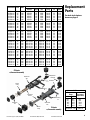
Replaceable Parts
Element Mounting Check
Box
O-ring
Kit
Valve
RTBCB
TMM-OR
FK2
RV-M
RTBCB
TMM-OR
FK2
RV-M
RTBCB
TMM-OR
FK2
RV-M
RTBCB
TMM-OR
FK2
RV-M
RTBCB
TMM-OR
FK2
RV-M
RTBCB
TMM-OR
FK2
RV-M
Element
Tank
1500
1500
1500
1500
1500
1500
RECB1151
RECB1158
RECB1152
RECB1157
RECB1153
RECB1154
RTB
RTB
RTB
RTB
RTB
RTB
120
208
240
380
480
2000
2000
2000
2000
2000
RECB1201
RECB1208
RECB1202
RECB1203
RECB1204
RTB
RTB
RTB
RTB
RTB
RTBCB
RTBCB
RTBCB
RTBCB
RTBCB
TMM-OR
TMM-OR
TMM-OR
TMM-OR
TMM-OR
FK2
FK2
FK2
FK2
FK2
RV-M
RV-M
RV-M
RV-M
RV-M
CB125100-000
CB125800-000
CB125200-000
CB125700-000
CB125300-000
CB125400-000
CL130100-100
CL130800-100
CL130200-100
CL130700-100
CL130300-100
CL130400-100
CL140800-100
CL140200-100
CL140700-100
CL140300-100
CL140400-100
120
208
240
277
380
480
120
208
240
277
380
480
208
240
277
380
480
2500
2500
2500
2500
2500
2500
3000
3000
3000
3000
3000
3000
4000
4000
4000
4000
4000
RECB1251
RECB1258
RECB1252
RECB1257
RECB1253
RECB1254
RECL1301-100
RECL1308-100
RECL1302-100
RECL1307-100
RECL1303-100
RECL1304-100
RECL1408-100
RECL1402-100
RECL1407-100
RECL1403-100
RECL1404-100
RTB
RTB
RTB
RTB
RTB
RTB
RTL
RTL
RTL
RTL
RTL
RTL
RTL
RTL
RTL
RTL
RTL
RTBCB
RTBCB
RTBCB
RTBCB
RTBCB
RTBCB
RTBCL-100
RTBCL-100
RTBCL-100
RTBCL-100
RTBCL-100
RTBCL-100
RTBCL-100
RTBCL-100
RTBCL-100
RTBCL-100
RTBCL-100
TMM-OR
TMM-OR
TMM-OR
TMM-OR
TMM-OR
TMM-OR
TML-OR
TML-OR
TML-OR
TML-OR
TML-OR
TML-OR
TML-OR
TML-OR
TML-OR
TML-OR
TML-OR
FK2
FK2
FK2
FK2
FK2
FK2
FK6
FK6
FK6
FK6
FK6
FK6
FK6
FK6
FK6
FK6
FK6
RV-M
RV-M
RV-M
RV-M
RV-M
RV-M
RV-M
RV-M
RV-M
RV-M
RV-M
RV-M
RV-M
RV-M
RV-M
RV-M
RV-M
CL150800-100
CL150200-100
CL150700-100
CL150300-100
CL150400-100
208
240
277
380
480
5000
5000
5000
5000
5000
RECL1508-100
RECL1502-100
RECL1507-100
RECL1503-100
RECL1504-100
RTL
RTL
RTL
RTL
RTL
RTBCL-100
RTBCL-100
RTBCL-100
RTBCL-100
RTBCL-100
TML-OR
TML-OR
TML-OR
TML-OR
TML-OR
FK6
FK6
FK6
FK6
FK6
RV-M
RV-M
RV-M
RV-M
RV-M
Replacement
Parts
For tank-style heaters
shown on page 8
CB Heater
w/thermostat assembly
Replacement
Thermostat
Replacement
Tank
Check Valve
Element
O-Ring
Mounting
Kit
Replacement
Element
Mounting
Kit
Replacement
Box
Replacement
Tank
Element
O-Ring
Customer Support: (509) 536-8660
Toll-Free FAX: (800) 224-5550
CL Heater
w/thermostat assembly
www.kimhotstart.com
Heaters with Thermostats
Temperature
Thermostat
Range
Replacement
ON
OFF
60°F
80°F
100°F
120°F
140°F
80°F
100°F
120°F
140°F
160°F
Adjustable 90° - 130°F
RSU6
RSU8
RSU10
RSU12
RSU14
RSU90-130
9
The right choice for hauling,
harvesting, plowing and lifting
Too bad all choices can’t be this easy.
EXIDE Heavy Duty Batteries.
Start Positive. Stay Positive.
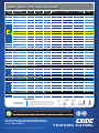
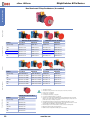
EXIDE HEAVY DUTY COMMERCIAL SERIES BATTERIES
A HEAVY DUTY BATTERY FOR EVERY HEAVY DUTY JOB.
From farm to factory and everywhere in between, there’s an Exide Heavy Duty Battery
with the power to get the job done. Whether you drive all day in rugged terrain, run
your lights at night in the field, or need high CCA for frigid starts in the morning, our
complete lineup has it covered. And it’s all backed with world-class sales support,
service and distribution through our nationwide branch network. From the construction
site to the loading dock, Exide Heavy Duty Batteries are ready when you are.
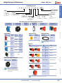
EXIDE ® HEAVY DUTY SPECIFICATIONS
BCI
GROUP
SIZE
PART NUMBER
CCA
@ 0º F
CCA
@ 32º F**
RC
MIN
@25A
EXIDE® HEAVY DUTY Commercial Series & Farm Batteries — 12 VOLT
3EE
F-3EE
370
440
100
3ET
F-3ET
460
550
120
4D
COM-4D-P
1000
1200
320
4DLT
F-4DLT
820
970
250
1300
1560
435
COM-8D
COM-8D (312)
1300
1560
435
COM-8D (313)
1300
1560
435
COM-8D (314)
1300
1560
435
COM-8D
(316)
1300
1560
435
8D*
COM-8D-P
1155
1380
400
COM-8D-P (312)
1155
1380
400
COM-8D-P (313)
1155
1380
400
COM-8D-P (314)
1155
1380
400
COM-8D-P (316)
1155
1380
400
COM-8D-PS
1155
1380
400
16TF
F-16TF
545
665
210
17TF
F-17TF
530
665
140
30H
COM-30H
700
850
180
10-5/16
10-5/16
10-5/16
EXIDE® HEAVY10-5/16
DUTY Commercial
Series & Farm
Batteries 10-5/16
— 6 VOLT
1
COM-1H-P
625
750
160
2
COM-2-P
625
750
150
2E
F-2E
615
675
180
3EH
F-3EH
850
1020
280
4
F-4EC-P
975
1170
300
4EH
F-4EH
930
1110
300
5D
COM-5D
850
1020
280
7D
COM-7D
975
1170
330
10-5/16
10-5/16AGM Batteries
10-5/16
10-5/16
10-5/16
EXIDE® RoadForce®
— 12 VOLT
XRF-31D
925
1110
200
XRF-31E
925
1110
200
31
RF-31D
700
840
200
RF-31E
700
840
200
10-5/16
10-5/16
10-5/16
EXIDE® Extreme
Cycler 200 Group
31 Battery10-5/16
— 12 Volt 10-5/16
31
EXHC-200D
700
840
200
10-5/16
10-5/16 — 12 Volt
10-5/16
10-5/16
EXIDE® Select10-5/16
PerformanceTM Batteries
XHP-31D
950
1100
190
XHP-31E
950
1100
190
HP-31D
925
1050
180
31
HP-31E
925
1050
180
HC-31D
700
840
180
HC-31E
700
840
180
10-5/16
10-5/16
10-5/16
10-5/16
EXIDE® HEAVY10-5/16
DUTY Commercial
Series Batteries
— 12 VOLT
COM-31E
660
800
160
31
COM-31D
660
800
160
LENGTH
OVERALL DIMENSIONS IN INCHES
WIDTH
19-1/4
19-1/4
19-9/16
20
20-3/4
22-5/16
22-5/16
22-5/16
22-5/16
20-7/8
22-5/16
22-5/16
22-5/16
22-5/16
20-7/8
16-1/2
17
13
10-5/16
8-13/16
10-1/4
19-3/8
19-1/4
13
19-1/4
13-1/2
15-7/8
10-5/16
13
13
13
13
10-5/16
13
10-5/16
13
13
13
13
13
13
10-5/16
13
13
4-1/4
4-1/4
8-5/16
8-1/8
11
11
11
11
11
11
11
11
11
11
11
7-1/8
6-7/8
6-15/16
10-5/16
6-3/4
6-7/8
4-1/8
4-1/4
6/3/4
5
7-1/4
7-1/4
10-5/16
6-5/8
6-5/8
6-5/8
6-5/8
10-5/16
6-13/16
10-5/16
6-13/16
6-13/16
6-13/16
6-13/16
6-13/16
6-13/16
10-5/16
6-13/16
6-13/16
HEIGHT
8-9/16
9-9/16
10
8-1/8
10
10
10
10
10
10
10
10
10
10
10
11-1/16
7-7/8
9-5/8
10-5/16
8-5/8
9-5/16
9-1/8
9-7/8
9-1/4
10
9-3/8
9-3/8
10-5/16
9-7/16
9-7/16
9-7/16
9-7/16
10-5/16
9-5/16
10-5/16
9-7/16
9-3/8
9-7/16
9-3/8
9-7/16
9-3/8
10-5/16
9-7/16
9-3/8
TERMINAL
TYPE
A
A
A
A
A
*B(312)
*B(313)
*B(314)
*B(316)
A
*B(312)
*B(313)
*B1(314)
*B(316)
T
A
A
A
10-5/16
A
A
A
A
A
A
A
A
10-5/16
T
M (3/8)
T
M (3/8)
10-5/16
T
10-5/16
T
A
T
A
T
A
10-5/16
T
A
TERMINALS
D=Stud Terminal
E=SAE Terminal
Plan-312 (BCI type B) side/bus terminal with 3/8” negative and positive threaded terminals.
Plan-313 (BCI type B) side/bus terminal with 3/8” negative and 1/2” positive threaded terminals.
Plan-314 (BCI type B1) side/bus terminal with 3/8” negative and positive threaded terminals.
Plan-316 (BCI type B) side/bus terminal with 3/8” negative and positive threaded terminals.
TYPE A
TYPE B
TYPE B-1
TYPE M
TYPE T
* Note special terminal configuration for 8D batteries.
** Note CCA@ 32º F is a reference rating.
Exide uses a comprehensive business approach to recycling called Total Battery Management (TBM)™. TBM includes manufacturing and
distribution of lead-acid batteries, collection of spent batteries, reclamation of battery materials and use of those materials in new batteries.
the materials to new product and diverting them from the waste stream. Exide Technologies batteries are recyclable.
For more information and nationwide warranty
terms visit us at www.StartPositiveStayPositive.com
or call 1-800-START-IT
©2011 Exide Technologies. Exide Technologies Milton, GA 30004 U.S.A. MKTG2029 5/11 DP
TM
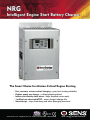
NRG
Intelligent Engine Start Battery Charger
The Smart Choice for Mission-Critical Engine Starting
•
•
•
•
•
Fast, accurate, mission-critical charging – gives best starting reliability
Replace nearly any charger – without planning ahead
Industry-first battery-fault alarm - helps dispatch service early
1 million hour observed MTBF – means longest charger life
Smart design – stops load dump and other damaging transients
www.sens-usa.com • [email protected] • Toll-free 866.736.7872 • 303.678.7500
Our energy means business ®
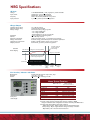
NRG Battery Charger Benefits and Features
Failure to start due to battery problems is the
leading cause of inoperable engine generator sets.
SENS NRG battery charger maximizes starting system reliability while slashing genset servicing costs:
One NRG replaces almost any charger without extra site visits. Installers can select or change at
any time 120, 208 or 240 volts AC input, 12 or 24-volt battery and output settings optimized for nearly
any lead-acid or nickel cadmium battery.
Easy to understand user interface provides state-of-the-art system status – including digital
metering, NFPA 110 alarms and a battery fault alarm that can send service personnel to the site
before failure to start.
Batteries charged by NRG give higher performance and last longer. In uncontrolled environments
precision charging by SENS increases battery life and watering intervals
400% or more.
NRG meets all relevant industry standards – including UL, NFPA 110 and CE. All units are either C-UL
listed or C-UL recognized. 50/60 Hz units add CE marking to UL agency marks.
EnerGenius reliability technology built into every charger includes:
• All-electronic operation with generous component de-rating
• Disconnected/reversed/incorrect voltage battery alarm and protection
• Protection of connected equipment against load dump transients
• Widest temperature rating, and overtemperature protection
• Superior lightning and voltage transient protection
• Demonstrated field MTBF > 1 million hours
• Standard 3-year warranty and available reimbursement of customer field service costs
Earn the best return on your charger
investment – choose SENS NRG
NRG Specifications
AC Input
Voltage
Input current
110-120/208-240 VAC, +10%, single phase, switch selectable
10A charger: 6.6/3.3 amps maximum
20A charger: 12.6/6.3 amps maximum
60 Hz +5% standard; 50/60 Hz +5% optional
1-pole fuse, soft-start, transient suppression
Frequency
Input protection
Charger Output
Nominal voltage ratings
Optional voltage rating
Battery settings
12 or 24 volt nominal
12/24 volt, field selectable
Six discrete battery voltage programs
- Low or high S.G. flooded
- Low or high S.G. VRLA
- Nickel cadmium 9, 10, 18, 19 or 20 cells
+0.5% (1/2%) line and load regulation
10 or 20 amps nominal
105% rated output typical – no crank disconnect required
Constant voltage, current limited, 4-rate automatic equalization
Enable or disable anytime, remote sensor optional
Current limit, 1-pole fuse, transient suppression
Regulation
Current
Electronic current limit
Charge characteristic
Temperature compensation
Output protection
Standard
4-rate charging
Fast volt limit
Charger in “fast charge mode”
Battery voltage
Float volt limit
Current limit
Transition from fast
charge voltage to
float voltage
Charger in “float mode”
Transition from current limit
to fast charge voltage limit
� ������ � ������ �� � ������ �
Constant current charge
High-rate Finishing
taper
charge
charge
Maintaining
charge
User Interface, Indication and Alarms
Digital meter
Accuracy
Alarms
Switch-selectable meter for output volts, amps
+2% volts, +5% amps
LED and Form C contact(s) per table:
����� ������ ���������
����� ���� ����
����� ���� ���
������ ������������ �� ���� ����
Front panel
status display
�� ����
����� ����
���� ������
���� ���� ������
�� ����
��� ������� �����
���� ������� �����
������� ����
������� ������
���
���
���
���
����
����
����
���
���
���
���
��� ��� ���� � �������
��� ��� ���� � �������
��� ��� ���� � �������
��� ��� ���� � �������
��� ��� ���� � �������
1. Alarms “1” available only on 10A charger
2. Form C contact provides summary alarm of these conditions. BBHH
chargers include this alarm configuration. Contacts rated 2A @ 26 VDC resistive
3. Battery fault alarm indicates these fault conditions:
- Battery disconnected - Battery polarity reversed - Mismatched charger
battery voltage - Open or high resistance charger to battery connection
- Open battery cell or excessive internal resistance
Controls
AC input voltage select
Optional 12/24-volt output select
Battery program select
Fast charger enable/disable
Temp compensation enable
Remote temp comp enable
Environmental
Operating temperature
Over temperature protection
Humidity
Vibration (10A unit)
Transient immunity
Agency Standards
Safety
Agency marking
EMI
NFPA standards
Optional agency compliance
Construction
Housing/configuration
Packaging
Dimensions
Printed circuit card
Cooling
Protection degree
Damage prevention
Electrical connections
Warranty
Standard warranty
Optional warranty
Optional features
Input
Remote temp comp sensor
Drip shield
NEMA 3R housing
UL BBHH listing
Field service warranty
Field-selectable switch
Field-selectable two-position jumper
Field-selectable six-position jumper
Field-selectable two-position jumper
Standard. Can be disabled or re-enabled in the field
Connect optional remote sensor to temp comp port
Simple field
adjustments
-20C to +60C, meets full specification to +45C
Gradual current reduction to maintain safe power device temperature
5% to 95%, non-condensing
UL 991 Class B (2G sinusoidal)
ANSI/IEEE C62.41, Cat. B, EN50082-2 heavy industrial
C-UL listed to UL 1236 (required for UL 2200 gensets), CSA standard 22.2
no. 107.2-M89
CE: 50/60 Hz units DOC to EN 60335
60 Hz: C-UL-US listed
50/60 Hz: C-UL-US listed plus CE marked
FCC Part 15 Class B; EN 50081-2
NFPA 70, NFPA 110. (NFPA 110 requires Alarms “C”)
Units with Alarms “1” configuration available with additional compliance to UL
category BBHH and NFPA 20
Material: Heavy clear anodized aluminum. Configuration options:
• Fully enclosed: C-UL listed enclosure
• Open frame: C-UL recognized
• Slimline: C-UL recognized open frame construction with remote isolation transformer
Open-frame and Slimline configurations only available in bulk OEM quantities and packaging
See Drawings and Dimensions page for details
Surface mount technology, conformal coated
Natural convection
Listed housing: NEMA-1 (IP20). Optional NEMA 3R enclosure
Fully recessed display and controls
Compression terminal blocks
Three year parts and labor warranty from date of shipment
If specified at time of order, warranty coverage is increased to reimburse customer’s documented
field service costs up to the original charger price. Contact the factory for full details
Input frequency, 50/60 Hz
Recommended where battery and charger are in different locations
Protects from dripping water
Enables outdoor installation (remote temp sensor recommended)
Available in 10A units with Alarms “1”
Reimbursement of customer field service expenses
up to charger price
Drawings and Dimensions
10A Chargers
10A Chargers
Enclosed and Open Frame Configurations
Slimline Open Frame Configuration
�����
����
���
�����
������
�
����
����
Slimline can be mounted either flat or edgewise
���
����
�����
����
Open-frame configuration omits front cover
20A Chargers
Enclosed and Open Frame Configurations
�����
�����
������
�����
�����
����
Open-frame configuration omits front cover
������� ���������� �����
����
�������������
��
��������
��
����������
��
�������� � ���� �����
��
�������� � ���� �����
��
��������
��
����������
�����
����� ���� ���
����� ���� ���
����� ���� ���
����� ��� ���
������ ���� ���
������ ���� ���
�����
����� ���� ���
����� ���� ���
����� ��� ���
����� ���� ���
����� ���� ���
����� ���� ���
������
������ ���� ���
������ ���� ���
����� ���� ���
����� ���� ���
������ ���� ���
������ ���� ���
111009 B
��� �������� �����������
������
�����
��
��
��
��
�����
�����
��
��
�����
������
����
��
��
��
��
��
��
��
��
��
�����
��������� ��������������
�����������
�����������
�����������
�����������
�����������
�����������
�����������
�����������
�����������
��������� ����������� ��������
��������� ��������
��������� ����������� ��������
��������� ��������
��������� ����������� ��������
��������� ��������
��������� ����������
��������� ����������
��������� ����������
���� ���
������
��
���
��
���
��
���
���
���
���
������
�� � ���
�� � ���
�� � ����
�� � ����
�� � ����
�� � ����
�� � ����
�� � ����
�� � ����
All models offer field-selectable input 120/
208-240 volts. 60 Hz input is standard
with C-UL listing. Optional 50/60 Hz input
includes C-UL listing and adds CE mark.
����� ������ ��������
���
—
—
Model Output voltage
Output current
10: 10 amps
12: 12 volts
20: 20 amps
24: 24 volts
22: 12/24-volt
field selectable
UL category code
S: UL category BBGQ (standard)
H: UL category BBHH (Alarms “1” only)
AC input
R: 120/208-240 VAC, 60 Hz
H: 120/208-240 VAC, 50/60 Hz
Alarm system code
1: LED and single Form C contact
C: LEDs and Form C contacts to meet
NFPA 110
Housing/Agency
L: Enclosed: C-UL listed
R: Open-frame: C-UL
recognized
S: Slimline open-frame: C-UL
recognized (10A only)
The Smart Choice for Mission-Critical Engine Starting
Additional Information
Contact SENS or your local sales representative for additional specification, engineering and installation information
Contact Information
For information and service on any SENS product, please contact us at:
Sales 1.866.736.7872 • 303.678.7500 • Fax 303.678.7504
www.sens-usa.com • [email protected]
1840 Industrial Circle, Longmont, CO 80501 USA
STORED ENERGY SYSTEMS
Our energy means business®
InteliGen
NT
GENERAL PURPOSE HIGH-END
GEN-SET CONTROLLER
Description
InteliGenNT is a comprehensive controller
for both single and multiple gen-sets
operating in standby or parallel modes.
Compact construction is optimized
for these purposes and various HW
modifications allow customers to select the
optimum type for a particular application.
A built-in synchronizer and digital
isochronous load sharer allow a total
integrated solution for gen-sets in
standby, island parallel or mains
parallel. Native cooperation of up to
32 gen-sets is a standard feature.
InteliGenNT supports many standard
ECU types and is specially designed
to easily integrate new ones.
A powerful graphic display with
user-friendly controls allows any
user whatever their ability to find
the information they need.
ComAp is able to offer customized
firmware solutions.
Benefits
GENERATOR MONITORING AND PARALLELING CONTROLS TO
COMPLY WITH 263213D,2.5 & 2.7
GENERATOR MONITORING TO CONNECT TO SEIMENS BMS
ComAp is a member of
AMPS (The Association of
Manufacturers of Power
generating Systems).
ComAp products meet the highest
standards, with every stage of production
undertaken in accordance with the ISO
certification obtained in 1998.
Selected ComAp
products have
the UL Certification.
Support of engines with ECU
(Electronic Control Unit)
Excellent configurability to match
customers’ needs exactly
Complete integrated gen-set solution
and signal sharing via CAN bus –
minimum external components needed
Many communication options – easy
remote supervising and servicing
Perfect price / performance ratio
Gen-set performance log for
easy problem tracing
Features
Integrated fixed and
configurable protections
InteliGenNT
Support of engines with ECU (J1939, Modbus and other
proprietary interfaces); alarm codes displayed in text form
AMF function
Automatic synchronizing and power
control (via speed governor or ECU)
Baseload, Import / Export
Peak shaving
Voltage and PF control (AVR)
Generator measurement: U, I, Hz, kW,
kVAr, kVA, PF, kWh, kVAhr
Mains measurement: U, I, Hz, kW, kVAr, PF
Inputs and outputs configurable for
various customer needs
Controller redundancy
RS232 / RS485 interface with Modbus support;
Analog / GSM / ISDN / CDMA modem support;
SMS messages; ECU Modbus interface
Event-based history (up to 500 records)
with customer-selectable list of stored
values; RTC; statistic values
Integrated PLC programmable functions
Interface to remote display unit (IG-Display LT GC)
Dimensions 180 × 120 mm (front panel)
Sealed to IP65
3 phase integrated generator protections (U + f)
IDMT overcurrent + Shortcurrent protection
Overload protection
Reverse power protection
Earth fault protection
3 phase integrated mains protections (U + f)
Vector shift protection
All binary / analog inputs free configurable for
various protection types: HistRecOnly / Alarm Only
/ Alarm + History indication / Warning / Off load /
Slow stop / BreakerOpen&Cooldown / Shutdown /
Shutdown override / Mains protect / Sensor fail
Phase rotation and phase sequence protection
Additional 160 programmable protections configurable for
any measured value to create customer-specific protections
Application security
ANSI CODES
ANSI
code
InteliGenNTC – All items from InteliGenNT plus:
Selectable measurement ranges for AC voltages
and currents – 120 / 277 V, 0–1 / 0–5 A
Secondary isolated RS232 / RS485 interface
USB 2.0 slave interface
ANSI
code
Protection
Protection
59
Overvoltage
27
Undervoltage
47
Voltage asymmetry
25
Synchronism check
81H
Overfrequency
47
Phase rotation
81L
Underfrequency
37
Undercurrent*
50+51
51N+64 Earth
32R
Reverse power
Overcurrent
55
Power factor*
46
Current unbalance
71
Gas (fuel) level
32
Overload
* can be created using universal protections
Schematic diagram
U coms. )
tary EC
...
Proprie /CUMMINS,
US
(MODB
VISION
or
PLAY LT
#32
IG-DIS
IGS-NT
PC
or
#1
M
MODE
1)
RS 232(
ACE
INTERF
INTER- LLER
CONTRO RING
TO
& MONI
CAN2
IGS-NT
INTELI
GC
SUPPLY
POWER VDC
8 TO 36
+
12
PC
M
MODE
PC
ION
EXTENS S
LE
MODU
CAN1
16/8
IS-BIN
ATOR
GENER
MAINS
OUT
NT
EME
SUR E
MEA OLTAG
V
T
REN
CUR ULT
FA T
TH
N
EAR URRE
C
OUT
i
AVR
OG
3 ANAL
INPUTS
SG
E
M
IGS-PT
trol
Con
l
ntro
o
B. C
3ph
1ph
s C.
. B.
rC
erato
Gen
id
leno
AVRi
3ph
3ph
1ph
er
LE:
DONG
IONAL
OPT
l So
Fue
10
3
Start
I-LB+
8
I-AOUT
Main
RY
12 BINA
TS
OUTPU
(OPEN TOR)
COLLEC
8
IS-AIN
E
TAG
VOL
T
REN
CUR
IG
TS
RY INPU
12 BINA
USB
2)
RS485(
RS232/
RFACE
1)
RS485(P. LT GC INTE TC only)
IS
-N
-D
(IG
IG
or
TER
CONVER
for
1)
RS232(
-NTC
-NT/IG
ENGIN
IG-IB
8
15
IGL-RA
VISION
INTELI
MAINS
8
GINE
I-CB/XX
ECU
OR
GOVERN
3 AVR
39
1
D
2 SPEE
J19
/GAS EN
DIESEL
InteliGen NT
LOAD
ATOR
GENER
CAN
-miniCHP
IGS-NT
MS
-LSM+P
IGS-NT +miniCHP
2
1
Protocol
U type
s on EC
depend
s.
com
ECU , ...)
tary M/CAT
prie
Pro TU, CC
EC/M
MS
-LSM+P
IGS-NT
(MD
3
Communication modules and
PC tools
Upgrade kits
I-CR – CAN repeater module
IG-IB – Internet bridge
I-LB+ – Local bridge
I-CB – ECU communication bridge
InteliMonitor – PC monitoring tool
InteliSupervisor – PC tool for Gen-set
or machines fleet management
WinScope – Special graphical controllers‘ monitoring software
GenConfig – PC configuration tool
IGS-NT-LSM+PMS dongle:
• Enables Multiple isolated parallel or
multiple parallel with mains
• Power management operation (with CAN bus)
• Digital Load Sharing
• Digital VAr Sharing
IGS-NT-miniCHP dongle:
• More PLC functions
IGS-NT-LSM+PMS+miniCHP dongle:
• Combination of the both dongles
HW modification codes
Extension modules and
remote displays
Order code IG-NT (LT) (GC) (Marine) or
IG-NTC (LT) (GC) (Marine)
up to 4× I-AOUT8 – Analog output extension module
IGL-RA15 – Remote annunciator
up to 4× IGS-PTM – Analog/binary input/output module
up to 10× IS-AIN8 – Analog input module
up to 10× IS-AIN8TC – Analogue input
module for thermocouples
up to 6× IS-BIN16/8 – Binary input/output module
up to 5× InteliVision 8 – Controller colour display unit
IG-Display LT GC – Additional remote display
LT = Low Temperature; display equipped with heating foil for
operation down to –40 °C
GC = Graphical Characters; one additional font (12 × 12, e.g.
Chinese or Korean) can be used on the display
Marine = Type approved version for Marine
Typical application
Visit www.comap.cz to see
more typical applications.
RENTAL SETS
Description:
Containerized rental gen-sets can
be used for maintenance of power
lines without interruption of power
delivery to end consumer.
Gen-sets are connected one-by-one to
mains at the consumer’s end and manually
loaded. Power line is then manually
disconnected and consumer is powered
from generators running in parallel.
The group of gen-sets is reverse
synchronized to mains after finalization of
maintenance on power line. InteliMainsNT
keeps generators and mains in synchronism
enabling manual reconnection to power line.
InteliMainsNT is built in a small
shock proof suitcase.
Interconnection of containers is done by
color coded not-interchangeable connectors.
Each gen-set can be used in Stand-by,
Single parallel to mains and Multiple
parallel modes according to the
position of Mode selector switch.
Frequency selector enables switching
between 50Hz / 230V and 60Hz / 277V mains.
LOAD
IG-NT
IG-NT
IG-NT
Scope of supply:
3× InteliGenNT
3× IGS-NT-LSM+PMS dongle
3× IG-AVRi
3× IG-AVRi-TRANS/LV
1× InteliMainsNT
InteliGen NT
IM-NT
InteliGenNT RELATED PRODUCTS
InteliGenNT Marine
HIGH-END MARINE CERTIFIED GEN-SET CONTROLLER
InteliGenNT Marine is a comprehensive controller for both single and multiple
gen-sets operating in standby or parallel modes for marine applications.
IS-NT-BB
InteliSysNT
or
PREMIUM AND COGENERATION
GEN–SET CONTROLLER
InteliSysNT is an expandable controller for both
single and multiple gen-sets operating in standby
or parallel modes, especially in cogeneration
(CHP) and other complex applications.
InteliSysNT = IS-NT-BB + IS-Display
or IS-NT-BB + InteliVision 8
InteliSysNT Marine
InteliVision 8
IS-Display
IS-NT-BB
or
PREMIUM MARINE CERTIFIED
GEN-SET CONTROLLER
InteliSysNT Marine is an expandable controller for
both single and multiple gen-sets operating in
standby or parallel modes for marine applications.
InteliSysNT Marine = IS-NT-BB + IS-Display Marine
or IS-NT-BB + InteliVision 8
InteliVision 8
IS-Display Marine
InteliMainsNT
MAINS SUPERVISION CONTROLLER
InteliMainsNT is designed for multiple (up to 31) gen-sets operating
in parallel to mains. The InteliMainsNT controller connects
the group of gen-sets to the mains. It can serve as a bus-tie
synchronizing controller between two groups of gen-sets.
MANUFACTURER:
LOCAL DISTRIBUTOR / PARTNER:
ComAp, spol. s r. o.
Czech Republic
Phone: + 420 246 012 111
Fax: + 420 266 316 647
E-mail: [email protected]
Internet: www.comap.cz
Customer satisfaction is our mission. We continuously develop the best people to succeed in our mission.
© ComAp. Features and specification are subject to change without prior notice.
2011-06/CPLEIGNT
InteliVision
CREATIVE ENGINEERING
CONTROLLER DISPLAY UNIT
Description
InteliVision is a new generation display unit
for either InteliGenNT / InteliSysNT or InteliDrive
controllers. It is designed as a simple, easy
to use Plug and Play solution and has been
developed from our original IS-Display.
The new InteliVision screen features many
significant improvements such as the large
high-resolution colour TFT display, which
helps visibility and definition for onscreen
information. The control interface has also
been updated with user-friendly intuitive
active buttons - giving users access to more
information in less time. InteliVision also
features our unique TRENDS monitoring
as a standard feature, helping you evaluate
past events easily on one screen.
The InteliVision cut-out size is the same as
the IS-Display (InteliSysNT), so InteliVision can
be easily used as a replacement for (or an
alternative to) IS-Display. Regardless of the
size it can be also used as a replacement for
(or an alternative to) IG-Display or I-RD-CAN.
InteliVision includes ComAp’s standard
communication interface using RS232/485
and CAN bus communication. Designed
to be mounted in both monitoring and
engine room, InteliVision gives complete
access to all control functions when
connected to InteliGenNT / InteliSysNT
or InteliDrive controllers.
Benefits
Large, high-resolution screen
Colour TFT display
TRENDS monitoring screen
Simpler, faster and more intuitive control
More information in less time
Same dimensions as IS-Display (InteliSysNT)
IS-NT-BB can be mounted to
the rear side of InteliVision
Plug and Play operation (auto configuration
based on controller application)
Universal solution for both controller
families - IGS-NT and ID
Direct connection to the controller
(converters are not needed)
ComAp is a member of AMPS
(The Association of Manufacturers
of Power generating Systems).
ComAp products meet the highest standards, with
every stage of production undertaken in accordance
with the ISO certification obtained in 1998.
InteliVision with InteliDrive controllers
(all possible connections)
Features
RS 232
CAN
VISION
INTELI
ID-DCU
VISION
INTELI
VISION
INTELI
CAN
ID-DCU
InteliVision with IGS-NT controllers
(all possible connections)
VISION
INTELI
2
CAN
* (1)
/RS232
RS485
2
2
3
4 INTELI
* (2)
/RS232
RS485
2
2
3
1
CAN
VISION
INTELI
IGS-NT
2
N
4 INTELIVISIO
IGS-NT
VISION
2
3
3
N
LIVISIO
INTE
one
rt only
32 po
*via RS2
IS-NT-BB
1
it can be
ion un
InteliVis
/ IG-NTC
IS-NT-BB
2
IG-NTC
3
4
Screens examples
/ IG-NT
1
/ IG-EEC
/ IG-EE
ted
connec
/ IG-EEC
3
N
4 INTELIVISIO
8" colour TFT display with
resolution of 800 × 600 pixels
Controlled by active buttons
Comes with new TRENDS
monitoring screen
Windows CE operating system
Same language support as
InteliGenNT / InteliSysNT and InteliDrive
Screen configuration by customer –
export to XML format with subsequent
manual screen modification and import
back to the controller (as IS-Display)
This display gives complete access to
all control and monitoring functions of
InteliGenNT / InteliSysNT and InteliDrive
Intended for connection to ONE
controller (InteliGenNT / InteliSysNT
or InteliDrive type)
The same dimensions as IS-Display /
InteliSysNT (including cut out dimensions)
It is possible to mount IS-NT-BB
to the rear side of InteliVision
Can be used as a replacement for
IG-Display, IS-Display or I-RD-CAN
Connection to a controller via
RS232/485 and CAN bus
Auto configuration based on controller
application (as IS-Display)
Designed to be mounted in both
monitoring and engine room
Operating temperature from
–20 to + 70°C (–4/158°F)
CE certification
Sealed to IP65
E
/ IG-E
IG-NT
MANUFACTURER:
LOCAL DISTRIBUTOR / PARTNER:
ComAp, spol. s r. o.
Czech Republic
Phone: + 420 246 012 111
Fax:
+ 420 266 316 647
E-mail: [email protected]
Internet: www.comap.cz
Features and specification are subject to change without prior notice
2007-11
Modules
Kit 1: iGL-RA15, Remote Annuciation Module
When NFPA110 approval is required the RA15 can be added for remote annunciation. Pictures
and features of the RA15 can be seen below.
Kit 1: iGL-RA15, Remote Annunciation Module
• 15 three-color LEDS
• CAN Bus connection to unit
• User definable labeling
• 1 connection for siren
• LED color is determined using the front
• Horn reset and lamp test keys
panel buttons(R/G/Y)
• Max. Distance is 200m
Please see next page
PROVIDE REMOTE E-STOP SWITCH PER 263213D,2.5,G
PTI4022 rev A
Governors America Corp.
720 Silver St.
Agawam MA 01001
Tel.: (413) 786-5600
Fax: (413) 786-5666
E-mail: [email protected]
Internet: www.governors-america.com
Oiltight Switches & Pilot Devices
ø22mm - HW Series
Display Lights
Switches & Pilot Lights
Non-illuminated E-Stop Pushbuttons (Assembled)
Ø40mm Head Pushlock Turn Reset
Contacts
Plastic Bezel
Metal Bezel
Plastic Bezel
Metal Bezel
Operator Only
HW1B-V3M†
HW4B-V3M†
HW1B-V4M†
HW4B-V4M†
1NO
HW1B-V3F10-M†
HW4B-V3F10-M†
HW1B-V4F10-M†
HW4B-V4F10-M†
1NC
HW1B-V3F01-M†
HW4B-V3F01-M†
HW1B-V4F01-M†
HW4B-V4F01-M†
1NO-1NC
HW1B-V3F11-M†
HW4B-V3F11-M†
HW1B-V4F11-M†
HW4B-V4F11-M†
2NO
HW1B-V3F20-M†
HW4B-V3F20-M†
HW1B-V4F20-M†
HW4B-V4F20-M†
2NC
HW1B-V3F02-M†
HW4B-V3F02-M†
HW1B-V4F02-M†
HW4B-V4F02-M†
Timers
Relays & Sockets
Ø29mm Head Pushlock Turn Reset
Terminal Blocks
Ø40mm Head EMO Pushlock Turn Reset
Contacts
Plastic Bezel
Metal Bezel
Plastic Bezel
Metal Bezel
Operator Only
HW1B-V4R-EMO-2*
HW4B-V4R-EMO-2*
HW1B-X4R*
HW4B-X4R*
1NO
HW1B-V4F10-R-EMO-2*
HW4B-V4F10-R-EMO-2*
HW1B-X4F10-R*
HW4B-X4F10-R*
1NC
HW1B-V4F01-R-EMO-2*
HW4B-V4F01-R-EMO-2*
HW1B-X4F01-R*
HW4B-X4F01-R*
1NO-1NC
HW1B-V4F11-R-EMO-2*
HW4B-V4F11-R-EMO-2*
HW1B-X4F11-R*
HW4B-X4F11-R*
2NO
HW1B-V4F20-R-EMO-2*
HW4B-V4F20-R-EMO-2*
HW1B-X4F20-R*
HW4B-X4F20-R*
2NC
HW1B-V4F02-R-EMO-2*
HW4B-V4F02-R-EMO-2*
HW1B-X4F02-R*
HW4B-X4F02-R*
ø60mm Head Pushlock Turn Reset
Circuit Breakers
Contacts
508
Ø40mm Head Pushlock Key Reset
Plastic Bezel
Operator Only
HW1B-V5R*
1NO
HW1B-V5F10-R*
1NC
HW1B-V5F01-R*
1NO-1NC
HW1B-V5F11-R*
2NO
HW1B-V5F20-R*
2NC
HW1B-V5F02-R*
1.
2.
2.
3.
5.
4.
7.
* Available in Red only.
† Available in red or yellow. Insert color code in place of M (R: Red, Y: Yellow).
For accessories, see page 549.
For dimensions, see page 551.
For nameplates and shrouds, see page 550.
For contact assembly part numbers, see page 550.
All HW series E-stops comply with EN418, the IEC “E-Stop Addendum to the Low Voltage
Directive,” this includes “tamper proof” operation whereby a change of contact state is not
possible by “teasing” or “floating” the operator.
8. All assembled part numbers in catalog include standard fingersafe (HW-F...) contacts.
9. Assembled units with spring-up terminals (HW-G...) can be ordered by removing an “F” from
the part number (Ex. HW1B-M1F11-R becomes HW1B-M111-R).
10. Units with exposed screw terminals (HW-C...) must be ordered as sub-components.
11. Operator only models include operator and button.
12. Additional contact configurations available (up to 6 total contacts).
www.idec.com
Oiltight Switches & Pilot Devices
ø22mm - HW Series
Part Number Structure
W
1
B
–
V
3
F
10 – R – EMO-2
Engraved Button*
Bezel
EMO-2: EMO switch
1: Plastic Bezel
4: Metal Bezel
Function
V: Pushlock Turn Reset
X: Pushlock Key Reset
(not available for 60mm
jumbo mushroom)
*Option available for red
EMO E-Stop only
Operator
3: ø29mm Head
4: ø40mm Head
5: ø60mm Head
Button Colors
Contact Arrangement
Terminals
F: Fingersafe
C: Exposed Screw
blank: Springup
10: 1NO
01: 1NC
11: 1NO-NC
R: Red
Y: Yellow
20: 2NO
02: 2NC
22: 2NO-2NC
Note: some switches only
available in red.
Display Lights
Non-illuminated E-Stop Pushbuttons (Replacement Parts)
Contact Blocks
+
Mounting Adaptor
+
Style
+
Anti-Rotation
Ring
+
Safety Lever Lock
Contacts
1NO
1NC
Standard
Fingersafe
(IP20)
HW-F10
HW-F01
HW-F10R
(early make)
HW-F01R
(late break)
HW-G10
HW-G01
HW-G10R
(early make)
HW-G01R
(late break)
Spring-Up
Terminal
Style
Part Number
Completed Unit
Anti-Rotation Ring
Appearance
Part Number
HW9Z-RL
Use with notched panel cutout to
prevent unit rotation.
Operators
Style
Plastic
Metal
HW-C01
red
HW1B-V3R
HW4B-V3R
HW-C10R
(early make)
HW-C01R
(late break)
yellow
HW1B-V3Y
HW4B-V3Y
red
HW1B-V4R
HW4B-V4R
yellow
HW1B-V4Y
HW4B-V4Y
ø40mm Head Pushlock Turn Reset
Timers
HW-C10
Dummy
Block
TW-DB
ø40mm Head EMO Pushlock Turn Reset*
Part Number
HW-CB2C
HW1B-V4R-EMO-2
HW4B-V4R-EMO-2
HW1B-X4R
HW4B-X4R
HW1B-V5R
–
ø40mm Head Pushlock Key Reset*
Circuit Breakers
1. Used to mount contact blocks to operator.
2. IDEC strongly recommends using the safety
lever lock to prevent heavy vibration or
maintenance personnel from inadvertently
unlocking contacts.
Terminal Blocks
Contact Block Mounting Adaptor
Style
=
HW9Z-LS
ø29mm Head Pushlock Turn Reset
Exposed
Screw
Terminal
Operator
Relays & Sockets
Contact Blocks
Safety Lever
Lock
Switches & Pilot Lights
H
ø60mm Head Pushlock Turn Reset*
1. *Available in red only.
2. All E-Stop buttons are not removable from the operator.
USA: 800-262-IDEC
Canada: 888-317-IDEC
509
PowerpactMhandout
2/2/05
8:55 AM
Page 1
Powerpact® M-Frame
Molded Case Circuit Breakers
Offering improved performance and efficiency
Powerpact M-Frame Molded Case Circuit Breakers provide improved
performance and a compact solution for up to 800A applications.
They complement the existing Powerpact P- and R-Frame, and
replace the traditional MA/MH Circuit Breakers with smaller footprint
and competitive cost.
Full-Featured Performance
Approximately 15% smaller installed volume than the MA/MH
Circuit Breakers
Same dimensions, common mounting, bussing, cabling and door
cut-out as Powerpact P-Frame Circuit Breaker
Share common accessories with Powerpact P-Frame Circuit
Breaker and can be field installed easily
Built-in electronic trip unit type ET 1.0 provides better accuracy
over standard thermal-magnetic trip unit
Fixed long-time and adjustable instantaneous protection
(2 to 10 times nominal Amps rating) is standard on all Powerpact
M-Frame Circuit Breakers
Connection options, including bus, standard lug, crimp lug and
distribution lug, are available for installation flexibility
Various padlocking and key-lock options are available to comply
with OSHA requirements
Dual rated UL489 and IEC 60947-2
Available 300A, 350A, 400A, 450A, 500A, 600A, 700A and
800A ratings
Available in 2- and 3-pole unit-mount and I-Line versions
Two levels of interrupting ratings available
Unit Mount Configurations
I-Line® Configurations
Standard
UL
Voltage
(V)
Int. Rating G
(kA)
Int. Rating J
(kA)
240
65
100
480
35
65
600
18
25
240
50/25
65/35
415
35/20
50/25
IEC Icu/Ics
PowerpactMhandout
2/2/05
8:55 AM
Page 2
Powerpact® M-Frame Molded Case Circuit Breakers
Features Comparison
Features
Amp Rating
2P and 3P
Interrupting
Rating (kA)
(240/480/600 V)
Powerpact M-Frame
Circuit Breaker Accessories
Square D®
MA/MH
Square D
Powerpact M
Square D
Powerpact P
300A – 1200A
300A – 800A
250A – 1200A
Yes
Yes
Yes
MA: 42/30/22
MH: 65/65/25
G: 65/35/18
J: 100/65/25
G: 65/35/18
J: 100/65/25
K: 65/50/50
L: 125/100/-
Shunt Trip (various AC and DC
voltages are available)
Undervoltage Trip (various AC and DC
voltages are available)
Time Delayed Undervoltage Trip
(various AC and DC voltages are
available)
Auxiliary Switches (up to 3A/3B
switches); Low-level (Volts and Amps)
switches are also available
Alarm Switch (1A/1B); Low-level
(Volts and Amps) switch is also
available
Yes
Yes
Thermal-Mag
(fixed Thermal)
LI (fixed long time
pick-up)
LI/LSI/LSIG
Trip Unit Power
Measurement
No
No
Yes
Standard Mechanical Lug (aluminum
or copper)
Trip Unit
Communication
No
No
Yes (Modbus –
open protocol)
Crimp (compression) Lug (aluminum
or copper)
Interchangeable
Trip Units
No
No
Yes
Power Distribution Lug (aluminum)
Bus Connector Kit
80/100% Rating
80%
80%
80 or 100%
Inter-Phase Barriers
Motor Operator/
Electrically Operated
Yes
No
Yes
Door Escutcheons (for toggle or
accessory cover)
Drawout
No
No
Yes
14 x 9 x 5
12.8 x 8.3 x 5.8
12.8 x 8.3 x 5.8
Padlocking Device (removable or fixed
version)
Key-lock Device (Kirk or Federal
Pioneer)
Trip Unit
Protection
Dimensions (inch)
HxWxD
Weight (lbs.)
34
30
32
All Rights Reserved
Yes
Dual Rated
UL489/ IEC 947-2
© 2005 Schneider Electric
Contact your Square D® sales
representative for additional information.
Or, visit www.us.squared.com
Schneider Electric - North American Operating Division
1415 S. Roselle Road
Palatine, IL 60067
Tel: 847-397-2600
Fax: 847-925-7500
Order Number 0612HO0401
03-04
Engine
Silencers
Silencers
- Compact
RFB Series
2 5 - 3 0 d BA
Critical Grade
Application & Performance
Call Silex for immediate assistance in
selecting the appropriate silencer that best
suits your application’s acoustical and
backpressure requirements or consult the
silencer selection guide in our catalogue. You
can also use Silex’s exclusive Silencer Sizing
and Selection Program “Silex Digital
Engineer” found on the Company’s secure
website at www.silex.com.
Compact Critical Grade series silencers are
combination type silencers and are designed
specifically for enclosures and marine
applications where space is limited. Silencers
are manufactured from light to heavy gauge
steel and finished with high temperature black
paint. Standard slip-on inlet up to 6”. Flange
inlet from 8”- 12”. Flanges are ANSI 125/150#.
Standard tube outlet on all sizes.
Typical Attenuation Curve
RFB-6
60
Attenuation - dB
Silencer Selection
50
40
30
20
10
0
63
125
250
500
1K
2K
4K
8K
Octave Band Center Frequency - Hz
Dimensions
B
C
D
E
In
In (mm)
In (mm)
In (mm)
In (mm)
In (mm) In (mm) Lbs (Kg)
RFB-1.5 1.5 (38)
8.88 (226)
11.50 (292)
6.25 (159)
5.75 (146)
3.75 (95)
3 (76)
17 (8)
RFB-2
8.88 (226)
11.88 (302)
8.25 (210)
6.00 (152)
4.00 (102)
3 (76)
21 (10)
12 (305)
15.38 (391)
10 (254)
7.82 (199)
5.5 (140)
3 (76)
34 (16)
Model
2.0 (51)
RFB-2.5 2.5 (64)
RFB-3
F
G
Wgt.
3.0 (76)
16.00 (406)
19.94 (506) 11.25 (286)
9.81 (249)
7.50 (191)
4 (102)
50 (21)
RFB-3.5 3.5 (89)
16.00 (406)
20.50 (521) 13.50 (343)
10.13 (257)
7.50 (191)
4 (102)
61 (28)
4.0 (102) 16.00 (406)
21.00 (533) 17.50 (445)
10.31 (261)
7.50 (191)
5 (127)
72 (33)
23.25 (591)
18.5 (470)
11.38 (290)
8.5 (216)
5 (127)
87 (40)
120 (54)
RFB-4
RFB-4.5 4.5 (115)
18 (458)
RFB-5
5.0 (127) 19.50 (495)
25.50 (648) 19.50 (495)
12.50 (318)
9.50 (241)
5 (127)
RFB-6
6.0 (152) 19.50 (495)
26.75 (679) 25.50 (648)
13.13 (334)
9.50 (241)
5 (127)
172 (78)
RFB-8
8.0 (203) 26.50 (673)
35.50 (902) 27.50 (699)
17.38 (441) 12.50 (318) 5 (127)
295 (134)
RFB-10 10.0 (254) 34.00 (864) 45.13 (1146) 33.50 (851)
22.25 (565) 16.00 (406) 5 (127)
500 (227)
RFB-12 12.0 (305) 40.00 (1016) 52.88 (1343) 40.50 (1029) 25.94 (659) 19.00 (483) 5 (127)
782 (355)
RFB-12
60
Attenuation - dB
A
50
40
30
20
10
0
63
125
250
500
1K
2K
4K
8K
Octave Band Center Frequency - Hz
Typical Orientations
Straight Through (ST)
Side Out (SO)
Side Discharge (SD)
Options
— Aluminized steel, 304, 316 or 316L stainless steel, Corten Steel
— Custom inlet/outlet configurations
— Thermal insulation blankets to suit all configurations
— Sample part number RFB-4-CCW-ST-C-B
Reverse Flow (RF)
Metric dimensions rounded to nearest mm.
Dimensions and weights are nominal and may vary slightly in
production models.
Silex Innovations Inc.
Phone
905 612 4000
Fax
905 612 8999
www.silex.com
Lit-0070
07-06
Products shown in counterclockwise
position. Also available in clockwise
800
387
7818
Corporate - 29395 Wall St. Wixom, MI 48393
West MI - 2385 Wilshere Drive Jenison, MI 49428
800.419.5199
Fax: 248.374.6408
Got Power? Generator Sales, Service & Rental
BILL OF MATERIAL FOR THE DAY TANK’s
Quantity
Description
(2)
SB20 - 250 Gallon Free Standing Day Tank
UL #142 Listed
Quantity
1
1
1
1
1
1
1
2
4
1
Part #
DW-101
3650
4300
3502
3005
1001
3152
3163
8410
Black
Standard Features
Tank Dim: 39"H x 50"W x 54"L Wt: 1250#
Double Wall Secondary Containment
Dip Tube Supply/Return Fitting Package (1/2” NPT)
Fuel in Basin Alarm (2" NPT, top mounted)
Basin Drain (1/2” NPT)
Locking Manual Fill Cap
Krueger Fuel Level Gauge (2" NPT, swing arm)
Standard Vent Cap (2” NPT)
Emergency Pressure Relief Cap (3” NPT)
Flush Mount Lifting Plate (minimum 4)
Paint Color Black
2
1
1
1
1
1
1
1
1
1
1
2
8310
NFPA
700-0007
700-0009
Special
1060
1099
1098
2010
6070
3600
3195
Options Included:
C-Channel Basin Support per MDEQ (C8 x 11.5)
NFPA Diamond Hazardous Material Decal for Diesel Fuel
Label - Diesel Fuel Only
Label - Combustible Liquids
Label – Keep Fire Away
(2) alarm panel mounted on day tank (Normal full & high level)
Low/Pump On/Pump Off/High Float Assembly
Lag Float (Set at 11") (For #2 supply pump control)
Reverse Pumping System (pump mounted on day tank top)
7 gpm Self Priming Pump, 3/8" Ports, 1/2 HP Motor 115 VAC
1/2" Diptube (7" Long)
Extra Piping Connection w/Plug (2" NPT) Spare
NOTE: This day tank includes a float sender to send signals to an existing Simplex pump controller, which controls
existing duplex supply pumps. This controller must also control the reverse pump being supplied with this day tank.
Standard 3 Year Standby Generator Set Comprehensive Warranty
Baldor’s warranty applies to all prod ucts manufactured by Baldor which are for use in the United States.
Baldor warrants that the p roduct is to be free from defects in materials and workmanship to the original
purchaser, for five (3) years or 1000 hours from date of delivery or start up.
Repair, replacement, or appro priate adjustment will be furnishe d if the defective part, upon Baldor’ s
inspection, is found to be properly installed, maintained, and operated in accordance with specifications to
which the p roduct was manufactured and in a ccordance with in struction manuals furnished by Baldor.
Labor for repair of a warrantable failure will be provided for three years from date of delivery not to exceed
published rates as contained in the B aldor Warranty Policy. One se rvice call per warrantable issue is
allowable under the Warranty Policy.
This warranty does not ap ply to malfunction s caused by damage , unreasonable use, misuse, repair o r
service by unautho rized persons, or norm al wear and tear. Any and all warranty repairs mu st be
authorized by Baldor prior to completion. A Start-up Inspection Form must be completed an d submitted
to Baldor in it’s entirety within 30 days of start-up to qualify for any warranty consideration.
NO OTHER EXPRESS WARRANTY APPLIES. Any implie d or s tatutory warranties, including any
warranty of merchantability or fitness of purpose, is expressly limited to the duration of this warranty. In
no event is Baldor liable for incidental or consequential damages.
This warranty shall not apply to cost of maintenance, adjustments, installation or start up; failures due to
normal wear, accident, misuse, abuse, neglect or improper installation; additions, alterations or
modifications not authorized in writing by Baldor; failures caused by defects in the system in which the set
is installed; rental equipment/expense while repairs are being made; starting batteries, fuses, light bulbs,
heating elements, engine fluids; components added to the set after shipment from Baldor.
This warranty shall not apply to block heaters or batteries after the first year.
No person is authorized to give any other warranties or to assume any other liabilities on Baldor’s behalf.
All claims must be brought to the attention of Baldor or an authorized distributor within thirty (30) days of
discovery of the part or parts failing to meet this warranty. No claims will be covered without advance
authorization or following proper procedures.