1
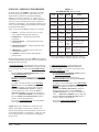
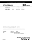
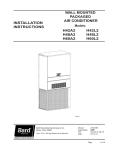
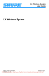
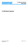
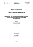
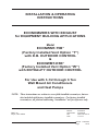
INSTALLATION & OPERATING INSTRUCTIONS ECONOMIZERS WITH EXHAUST for EQUIPMENT BUILDING APPLICATIONS Model ECONWMT-T5B* (Factory Installed Vent Option “T”) with D.B. OUTDOOR CONTROL & ECONWMT-E5B* (Factory Installed Vent Option “W”) with ENTHALPY OUTDOOR CONTROL For Use with 3-1/2 through 6 Ton Wall Mount Air Conditioners and Heat Pumps NOTE: These instructions are written to cover field-installed economizers, but are also included with factory installed economizers. For factory installed economizers, all portions addressing “installation” are for reference only. BMC, Inc. Bryan, Ohio 43506 Manual:2100-593C Supersedes:2100-593B File: Volume III Tab 19 Date:11-12-13 Manual2100-593C Page 1 of 23 CONTENTS GENERAL Nomenclature............................................................. 3 General Information................................................... 3 Unpacking.................................................................. 3 Description................................................................. 3 INSTALLATION Basic Installation (Field Installed).........................4 - 6 Outdoor Air Sensor Field Installation......................... 4 Control Wiring Connection......................................... 7 Intake Air Hood Assembly........................................ 13 Left-Hand Applications Only..................................... 13 JADE™ Economizer Controller................................ 15 Start-Up / Checkout Procedures.......................16 - 19 Enthalpy Settings..................................................... 19 Economizer Sequence of Operation Condition - Cool Outdoor Ambient Conditions...... 20 Condition - Warm Outdoor Ambient Conditions.... 20 Economizer Features............................................... 21 Economizer Operation for Single Stage................... 22 Economizer Operation for Two Stage...................... 23 FIGURES Figure 1 HVAC Unit Access Panels......................... 4 Figure 1ACondenser Exh. Plate w/Screen............... 5 Figure 2 Mixed Air Sensor Location........................ 7 Figure 3 Mixed Air Sensor Location........................ 7 Figure 4 24V Control Wiring w/1-Stage A/C............ 8 Figure 5 24V Control Wiring w/2-Stage A/C............ 9 Figure 6 24V Control Wiring w/1-Stage HP .......... 10 Figure 7 24V Control Wiring w/2-Stage HP........... 11 Figure 8 2-Stage HP w/Dehum. & Opt. Elec. Heat.... 12 Figure 9 Economizer Hood Install Steps............... 14 Figure 10 Left Hand Economizer............................. 15 Figure 11 Enthalpy.................................................. 19 Figure 12 100% Outside Airflow Path...................... 20 Figure 13 Mixed Airflow Path................................... 20 Figure 14 100% Closed Loop Airflow Path.............. 21 PHOTOS Photos 1 Photo 2 Photo 3 Photo 4 Op. Position Temp. & Enthalpy................. 5 Wire Harness............................................ 6 Low Voltage Terminal Block...................... 6 JADE™ Controller..................................... 6 TABLES Table 1 Economizer Application............................. 3 Table 2 System Setup.......................................... 16 Table 3 Advanced Setup...................................... 17 Table 4 Setpoints................................................. 17 Table 5 Checkout................................................. 18 Table 6 Status...................................................... 18 TableEnthalpy.................................................. 19 Table 7 Alarms..................................................... 19 Manual2100-593C Page 2 of 23 GENERAL ECONOMIZER WITH EXHAUST MODEL NOMENCLATURE ECON WM ECONOMIZER WALL MOUNT A/C or HP T T = Telcom/ Equipment Bldg. S = Standard – T T = Temperature E = Enthalpy 5 B CABINET SIZE 2 - 2 Ton 3 - 3 Ton 5 - 5 Ton (See Table 1) X REVISION COLOR OPTIONS X-Beige 1-White 4 - Buckeye Gray 5 - Desert Brown 8 - Dark Bronze GENERAL INFORMATION DESCRIPTION The economizer should only be installed by a trained heating and air conditioning technician. These instructions serve as a guide to the technician installing an economizer package, not as a step-by-step procedure with which the mechanically inclined owner can install the package. The ECONWMT-T5BX, -E5BX economizer is designed to be used with wall mount series air conditioners and heat pumps, shown in Table 1, equipped with low ambient controls. They are electromechanical economizer systems designed to provide “free” cooling where the outdoor air temperature/enthalpy is cool enough to provide the needed cooling without running the compressor, or in addition to the compressor. When cooling is required, the system automatically takes advantage of cold outdoor air when available and uses it for first stage cooling. This then reduces the need to run the air conditioning compressor providing lower operating costs and increasing the service life of the equipment. If the outdoor air temperature/enthalpy is too warm to be sufficient for cooling, the dry bulb outdoor air temperature sensor detects the condition and automatically closes the outdoor air intake/exhaust damper, opens the return air damper, and switches to compressor-only operation. Without attention from the end user, the economizer assembly is meant to automatically achieve maximum savings while ensuring appropriately cool space temperatures. The economizer utilizes a fully-modulating damper actuator, which will control intake/exhaust in order to obtain and maintain a factory-set minimum supply air temperature. As a secondary feature, the economizer assembly can be programmed for a minimum ventilation based on an “occupied” (or otherwise dedicated) 24V signal to satisfy fresh air ventilation on populated structures or dilution of internal pollutants. The economizer housing is shipped in one carton, which contains the electrical harness, miscellaneous hardware and installation instructions. The economizer installation requires the use of a 2-stage cooling thermostat (if there is not one already present) and requisite amounts of low voltage conductor wire for two-stage cooling. The number of low-voltage control conductors will vary depending upon application. If using a master controller, the MC4000 controller is designed specifically to control two (2) redundant wall mount units equipped with economizers. Any wall mount unit equipped with an economizer must also have a factory/field installed low ambient control. Refer to appropriate model/year Specification Sheet for requisite field installed low ambient control kit part numbers. UNPACKING Upon receipt of the equipment, be sure to compare the model number found on the shipping label with the accessory identification information on the orders and shipping document to verify that the correct accessory has been shipped. Inspect the carton housing of each economizer assembly as it is received, and before signing the freight bill – verify that all items have been received and there is no visible damage. Note any shortages or damage on all copies of the freight bill. The receiving party must contact the last carrier immediately, preferably in writing, requesting inspection by the carrier’s agent. Concealed damage not discovered until after loading must be reported to the carrier within 15 days of its receipt. NOTE: Factory installed Telcom economizers have the air intake hood shipped knocked-down. See “Intake Air Hood Assembly” section for shipping location of hood parts and follow the assembly instructions. TABLE 1 j MODEL ECONWMT-T5BX ECONWMT-E5BX FOR USE WITH FOLLOWING UNITS W38A WA3S S38H T36H J/W42A WA4S S43H T42H J/W48A WA5S S49H T48H W49A J/W42H S61H T60H J/W60A J/W48H J/W42L T36S W61A J/W60H J/W48L T42S J/W60L T48S J/W70L T60S J/W72A Low ambient control is required w/economizer for low temperature operation. ECONWMT Series Economizers are not for use with variable capacity ECU models. Manual2100-593C Page 3 of 23 INSTALLATION of FIELD (INSTALLED) ECONOMIZER BASIC INSTALLATION 1. Unpack the economizer assembly, which includes the integral economizer with attached electrical harness, mixed air sensor, body panels, miscellaneous hardware, and installation instructions. 2. From existing wall mount unit, remove and save Blower Access Panel. Remove and discard the Ventilation Access Panel. Remove and save the existing filter. (See Figure 1.) 3. Remove and discard the exhaust cover plate. (See Figure 1.) 4. Install new condenser exhaust plate with screen over the opening. (See Figure 1A.) Outdoor Air Sensor Field Installation a.) Disconnect power to the unit. b.)Install the outdoor air sensor in the lower condenser section on the side opposite the compressor with two (2) screws provided. Sensor should mount approximately ¼" above the base. (See Photo #1.) c.) Route the wire harness across the back of the units and secure to the back with the two (2) push mount wire ties provided. Route the wire harness up through the grommet in the bottom of the control panel and secure with the wire tie (provided) to the remaining wires in the grommet. Ensure the wire harness cannot contact any moving parts or hot tubes. (See Photo #2.) d.)Install a grommet in the side of the low voltage terminal block and route the wire harness through the low voltage terminal block and through the side of the control panel through the existing grommet. (See Photo #3.) e.) Route the wire harness up into economizer control box. (See Photo #4.) If a temperature only sensor, connect to the OAT terminals on the JADE™ controller. If an enthalpy sensor, connect to the SBUS terminals on the JADE™ controller. FIGURE 1 EXHAUST COVER PLATE BLOWER ACCESS PANEL FILTER NOTE: NEWER MODELS ALREADY HAVE THE BOTTOM SCREWS APPROXIMATELY 1" FROM THE CORNERS. IF NOT, DRILL IN ONE (1) SCREW AT EACH LOWER CORNER. FILTER ACCESS PANEL (THIS PANEL IS DISCARDED) VENT OPTION PANEL (THIS PANEL IS DISCARDED) SCREW NOTE: ON OLDER UNITS THIS WAS A 1-PIECE PANEL MIS-2964 B Manual2100-593C Page 4 of 23 NOTE: If you are installing this economizer assembly into a left-hand access wall mount, please stop here and proceed to specific instruction note on Page 13. PHOTOS #1 OPERATING POSITION TEMPERATURE ONLY 5. In the open cavity between the filter rack and the condenser section, begin to insert the main economizer assembly. Slide the assembly inside, being careful not to tear the existing insulation. Do not completely recess the assembly. (See Figure 2.) 6. Unravel the attached economizer wiring harness and separate the two (2) orange wires connected to a white, two-pin sensor plug. The remainder of the low voltage wires can be routed through the existing wiring grommet located near the bottom of the wall mount electrical control panel. (See Figure 2.) ENTHALPY FIGURE 1A CONDENSER EXHAUST PLATE WITH SCREEN SIDE PARTITION COVER PLATE INSTALL COVER PLATE SCREEN MEDIA FACING PARTITION PARTITION COVER PLATE PARTITION STIFFNER ANGLE SHOWN (HIDDEN) CONDENSER PARTITION MIS-3344 Manual2100-593C Page 5 of 23 PHOTO #2 PHOTO #3 ^ Wire Tie Locations ^ PHOTO #4 7. Pull wires gently through grommet so that low voltage wires protrude underneath wall mount terminal board. 10. Install temperature sensor bracket and mixed air temperature sensor in blower partition. Insert white two-pin sensor into sensor housing. (See Figure 3.) 8. Route two (2) orange wires connected to a white two-pin sensor plug along refrigerant lines and behind the filter bracket to terminate at the blower partition. (See Figure 2.) 11. Reinstall Blower Access Panel. NOTE: Newer models already have the bottom screws approximately 1" from the corners. If not, drill in one (1) screw at each lower corner. (Reference Figure 1.) 9. Fully seat economizer assembly to the rear of the wall mount cavity, making sure economizer control panel opposite filler strip is fully recessed into cabinet. (See Figure 2.) Manual2100-593C Page 6 of 23 12. Connect all low voltage leads to terminal board of wall mount unit as required according to installed equipment and controls. Figure 4 shows the basic economizer wiring, and is followed by typical control wiring diagrams for single unit applications. Refer to MC4000 Lead/Lag Controller Instructions Manual 2100-563 for dual unit control connections. FIGURE 2 INSTALL TEMPERATURE SENSOR TO BLOWER PARTITION. ROUTE WIRES FROM ECONOMIZER BEHIND FILTER BRACKET FILL AND THROUGH WIRE TIE. WIRE TIE TO SUCTION LINE LOW VOLTAGE WIRE TO TERMINAL STRIP FRONT VIEW FIGURE 3 TEMPERATURE SENSOR BRACKET PART #113-433 (SHOWN) USE BRACKET PART #113-468 FOR 2 & 3 TON UNITS TOP VIEW TEMPERATURE SENSOR PART #8602-058 (C7250A1001) MIS-2933 B NOTE: Since observation of motor/damper operation is difficult after air hood installation, it is recommended the unit be enabled for start-up now. If high voltage power is available and the wall mount unit can be energized, turn to Page 14 for programming and start-up/checkout procedures. If no power is available, or if immediate start-up is not desired, continue with the basic installation process. The air hood assembly can be partially disassembled at a later time for start-up/checkout procedures. CONTROL WIRING CONNECTION DIAGRAMS The control wiring diagrams on the following pages represent typical control wiring for W model and S model single unit installations with individual thermostats. If thermostats other than referenced are used, the installer must verify output functions and proper operation accordingly. Factory installed T and W vent options are wired per the appropriate wiring diagram in this manual. On H model units, factory installed T and W vent options are wired at the factory per Figure 7 of the MV4000 Series Lead/Lag Controller manual 2100-571. For H model dual installations utilizing the MV4000 lead/lag controller system, complete details are contained in the MV 4000 Series Lead/Lag Controller manual 2100-571. These economizers CAN NOT be used with the MD4000 Series Lead/Lag Controllers. For W model dual installations utilizing the MC4000 Lead/Lag Controller system, complete details are contained in the MC 4000 Series Lead/Lag Controller manual 2100-563. Manual2100-593C Page 7 of 23 FIGURE 4 1-STAGE A/C WITH OPTIONAL ELECTRIC HEAT WITH ECONWM STYLE ECONOMIZER Low Voltage Wiring Diagram 3 4 8403-058 (TH5220D1151) C G R RC Y2 Thermostat part #8403-060 C G R Y2 YO/D Y1 W1/E W2 A/C UNIT 24V TERMINALS C G R Y Y W W2 2 5 Y2 2 3 O/B A E F BLUE 1 PINK PURPLE YELLOW RED BLACK 6 Economizer Wiring Harness 1 W1 W2 L 2 TAPE WIRE END YELLOW/RED Y1 A ORANGE BROWN/WHITE YELLOW/WHITE Factory installed jumper. Remove for 2-stage operation 1 on units with 15 or more kw. 2 Must be energized to enable minimum position. NOTE: Economizer Control Default Setting is 10V (100%). Depending upon application may require setting to lower value. 3 Factory Jumper Installed. Change "system type", set up function 1, from 5 (2 heat/ 1 cool heat pump) 4 to 6 (2 heat/ 2 cool conventional). Change model configuration from heat pump to heat/cool, and must be configured for 5 economizer for YO/D output to be active as first stage cooling. 6 Manual2100-593C Page 8 of 23 Older units may not have Y1 and Y2 connections on 24v terminal block. If not present wire nuts must be used. MIS-2983 C FIGURE 5 2-STAGE A/C WITH OPTIONAL ELECTRIC HEAT WITH ECONWM STYLE ECONOMIZER Low Voltage Wiring Diagram 3 4 8403-058 (TH5220D1151) Y2 C G R RC Thermostat part #8403-060 C G R Y2 YO/D Y1 W1/E W2 A/C UNIT 24V TERMINALS C G R Y1 Y W W2 2 5 Y 1 Y2 W1 W2 2 3 A L O/B A E F Economizer Wiring Harness 2 TAPE WIRE END YELLOW/RED BLUE ORANGE PURPLE YELLOW RED BLACK 1 PINK BROWN/WHITE YELLOW/WHITE Factory installed jumper. Remove for 2-stage operation 1 on units with 15 or more kw. Must be energized to enable minimum position. NOTE: Economizer Control Default Setting is 10V (100%). Depending upon application may require setting to lower value. 3 Factory Jumper Installed. Change "system type", set up function 1, from 5 (2 heat/ 1 cool heat pump) 4 to 6 (2 heat/ 2 cool conventional). Change model configuration from heat pump to heat/cool, and must be configured for 5 economizer for YO/D output to be active as first stage cooling. 2 MIS-2984 C Manual2100-593C Page 9 of 23 FIGURE 6 1-STAGE HEAT PUMP WITH OPTIONAL ELECTRIC HEAT WITH ECONWM STYLE ECONOMIZER C R B Black Red W1 W2 L G E W2 L G A Y Brown/white 3 Economizer Wiring Harness YO/D Y2 Y1 Purple 24V Low Voltage Terminal Block W1/E Y1 DH O1 W3 Yellow/red O/B Yellow R 1 Orange C Blue Thermostat part #8403-060 Pink Low Voltage Wiring Diagram 2 Yellow/White 1 Must be energized to enable minimum position. NOTE: Economizer Control Default Setting is 10V (100%). Depending upon application may require setting to lower value. 2 Must be configured for heat pump / multistage/ no economizer/ to enable YO/D output to be active as dehumidification output 3 Factory Jumper Installed. MIS-2981 B Manual2100-593C Page 10 of 23 FIGURE 7 2-STAGE HEAT PUMP WITH OPTIONAL ELECTRIC HEAT WITH ECONWM STYLE ECONOMIZER Low Voltage Wiring Diagram C R B W1 W2 L G E W2 L G Y A DH O1 W3 Brown/white Orange Yellow 3 Y1 Y2 Economizer Wiring Harness Y1 YO/D 1 Purple 24V Low Voltage Terminal Block W1/E Pink O/B Blue R Red C Black Thermostat part #8403-060 Yellow/red 2 Yellow/White 1 Must be energized to enable minimum position. NOTE: Economizer Control Default Setting is 10V (100%). Depending upon application may require setting to lower value. 2 Must be configured for heat pump and economizer to enable YO/D output to be active as 1st-stage cooling 3 Factory Jumper Installed. MIS-2982 B Manual2100-593C Page 11 of 23 FIGURE 8 2-STAGE HEAT PUMP WITH DEHUMIDIFICATION & OPTIONAL ELECTRIC HEAT WITH ECONWM STYLE ECONOMIZER C R B W1 W2 L G E W2 L G A YO/D Y1 DH Economizer Wiring Harness Orange Brown/white Yellow 3 Y Y2 Y1 Purple 24V Low Voltage Terminal Block W1/E O1 W3 Yellow/Red O/B Blue R Red C Black Thermostat part #8403-060 Pink Low Voltage Wiring Diagram 2 1 Yellow/White 1 Must be energized to enable minimum position. NOTE: Economizer Control Default Setting is 10V (100%). Depending upon application may require setting to lower value. 2 Must be configured for heat pump / no economizer/ to enable YO/D output to be active as dehumidification output 3 Factory Jumper Installed. MIS-2995 B Manual2100-593C Page 12 of 23 INTAKE AIR HOOD ASSEMBLY The Telecom/Equipment Building version economizers utilize an air intake hood to maximize outdoor airflow performance and to be able to introduce this at low intake velocity. FACTORY INSTALLED ECONOMIZERS The main economizer assembly is installed in the unit’s ventilation cavity, but the air intake hood is shipped knocked down. The intake hood pieces are located on the back side of the A/C unit. NOTE: Some applications on equipment buildings necessitate the air intake hood assembly be shipped inside the building for installation at the final site. In this case, the solid panel covering the economizer section must be left in place to protect and weatherize the equipment during transit. ECONOMIZER HOOD INSTALLATION A.) For Factory Installed Economizer Only: Detach plate by removing three (3) screws and filter door. Discard cover plate and replace filter door. (See Step #1, Figure 9.) B.) For Field Installed Economizer Only: 1. Attach hood mounting door by inserting top lip under hook bend on upper panel. Use four (4) ½" hex head screws to fasten hood mounting door to unit. (See Step #1, Figure 9.) 2. Use four (4) screws to attach right side assembly and left side assembly. (See Step #3, Figure 9.) 3. Hood bottom requires pre-assembly of lower filter angle, bottom filter bracket, and bottom divider bracket. Attach lower filter angle to bottom filter bracket as shown in Step #4 using two (2) ½" hex head screws. Bottom filter bracket is then attached to primered non-textured side of base using two (2) ½" hex head screws. Bottom divider bracket is installed to painted textured side of base using three (3) ½" hex head screws. Paint side of bottom divider bracket is facing “down” lip on front of hood base. (See Step #4, Figure 9.) 4. Install hood top assembly to hood mounting door using three (3) ½" hex head screws. Side bends of top assembly should overlap left and right side assemblies. Attach top to side assemblies using four (4) ½" hex head screws. (See Step #5, Figure 9.) 5. Insert hood bottom assembly between side assemblies with back bend resting on hook bend of hood mounting door. Attach to left side assembly and right side assembly using four (4) ½" hex head screws. (See Step #5, Figure 9.) 6. Install mist eliminator and attach hood front using two (2) Phillips head retainer clip screws. (See Step #6, Figure 9.) LEFT-HAND APPLICATIONS ONLY 1. Before installation into wall mount cavity, rotate economizer 180° so JADE controller will now be adjacent to the wall mount unit control panel. (See Figure 10.) 2. Remove two (2) side angles and block off plate. (See Figure 10.) 3. Remove switch assembly by taking out two (2) screws. Reposition switch assembly and reattach using two (2) screws. (See Figures 10 & 11.) 4. Reinstall two (2) side angles in upper position. Reinstall block off plate in lower position. (See Figure 10.) 5. Loosen actuator shaft adaptor clamp from damper blade rod. (See Figure 10.) 6. Remove actuator assembly from economizer. (See Figure 10.) 7. Pull adaptor clamp retainer clip; remove adaptor clamp from actuator assembly and reinstall on the opposite side of the actuator on the “0” position. (See Figure 10.) 8. Reinstall actuator assembly with adaptor clamp facing away from the economizer assembly. (See Figure 10.) 9. Ensure position of the economizer damper is closed, then tighten shaft adaptor clamp. (See Figure 10.) 10. Hood mounting door will use alternate control panel door location. (See Figure 10.) Before installing hood, ensure switch is functioning properly in upper position (activated in closed blade position.) NOTE: Please resume the basic installation process at Step #4 on Page 4. Manual2100-593C Page 13 of 23 FIGURE 9 STEP 1 INSTALL HOOD MOUNTING DOOR (Field install only) STEP 2 REMOVE COVER PLATE AND DISCARD (Factory install only) FILTER DOOR SIDE COVER REMOVE FILTER ACCESS PANEL AND REPLACE ONCE COVER IS DICARDED (Factory install only) RE-INSERT SCREW TO HOLD CONTROL PANEL COVER AFTER PLATE REMOVAL RIGHT HAND UNIT ONLY. SEE CONVERSION INSTRUCTIONS FOR LEFT HAND VERSIONS CONTROL PANEL COVER STEP 3 STEP 4 1/2" HEX HEAD SCREWS BOTTOM FILTER BRACKET 1/2" HEX HEAD SCREWS LEFT SIDE ASSEMBLY LOWER FILTER ANGLE BASE PART #126-443 (PRIMERED SIDE) INSTALL HOOD SIDES TO HOOD MOUTNING DOOR INSTALL HOOD TOP AND HOOD BOTTOM TO SIDES AND MOUNTING DOOR STEP 5 RIGHT SIDE ASSEMBLY HOOD BOTTOM ASSEMBLY HOOD TOP ASSEMBLY STEP 6 INSTALL MIST ELIMINATOR (12) SCREWS PART #1012-086 ECONOMIZER BLADE SWITCH (5 TON UNIT ONLY) IS ALWAYS LOCATED AT TOP. SWITCH MUST BE RELOCATED FOR WXXL LEFT HAND UNITS BEFORE BAFFLE PLATE IS INSTALLED. FOR FIELD INSTALLED ECONOMIZERS, FOLLOW BASIC ECONOMIZER INSTALLATION INSTRUCTIONS FOR CONVERSATION TO LEFT HAND UNIT INSTALLATION. Manual2100-593C Page 14 of 23 INSTALL HOOD FRONT USING (2) ATTACHED RETAINER CLIP SCREWS MIS-3231 FIGURE 10 VIEW UNDER UPPER PARTITION (BLADE SWITCH DETAIL) MOVE SWITCH TO UPPER POSITION BLADE IN CLOSED POSITION MOVE SIDE ANGLES TO UPPER POSITION LEFT HANDED APPLICATION "0" POSITION MOVE BLOCK OFF PLATE TO LOWER POSITION DAMPER BLADE ROD LEFT HANDED ECONOMIZER ACTUATOR SHAFT ADAPTOR CLAMP LEFT HANDED CONTROL PANEL COVER CONFIGURATION SIDE COVER FILTER DOOR CONTROL PANEL COVER MIS-3232 JADE™ ECONOMIZER CONTROLLER W7220 Controller offers unparalleled flexibility and expansion in a dependable and solid electronic platform. • Multiple economizer applications from one controller. • Nearly limitless customization of setpoints. • Internal Checkout menu provides fast performance assessment. • Alarms menu provides assistance in troubleshooting. Memory: User defined setpoints remain in nonvolatile flash memory regardless of electrical outage duration. Control voltage below 18V may cause erratic performance. Manual2100-593C Page 15 of 23 START-UP / CHECKOUT PROCEDURES From the factory, the JADE™ economizer controller has been preset with “default” values that were predetermined as optimum for equipment buildings, and these are shown in Tables 2 - 4. However, it is important to review and/or customize these operational values per owner specifications in order to guarantee satisfactory performance. The installing contractor can easily access the JADE™ programming by the integral keypad and LCD display. There are six (6) basic MENU categories to navigate: 1. STATUS – provides real-time access to sensor input, damper and equipment operation. 2. SETPOINTS – customizable operational parameters. 3. SYSTEM SETUP – customizable application programming. 4. ADVANCED SETUP – further application and operational options. 5. CHECKOUT – instantly activate and verify economizer functions. 6. ALARMS – displays alarms and pinpoints problem areas. Before being placed in service, the JADE™ economizer controller programming should be reviewed/customized through the following steps: 1. SYSTEM SETUP: from the main screen, press the SCROLL (UP/DOWN) BUTTONS to navigate through the six (6) basic menu items to the SYSTEM SETUP menu. – Push the SELECT (ENTER) BUTTON to choose the SYSTEM SETUP menu. – Navigate through the multiple levels of SYSTEM SETUP by pushing the SCROLL (UP/DOWN) BUTTONS. – To change a specific parameter in the SYSTEM SETUP menu, press the SELECT (ENTER) BUTTON to display its current value. Press the SCROLL (UP/DOWN) BUTTONS to change or or increase/decrease value. Press the ELECT (ENTER) BUTTON to save the new customized value — “CHANGE STORED” will be displayed. Press the SELECT (ENTER) BUTTON again to return to current menu parameter. – For specific SYSTEM SETUP level information, refer to Table 2. NOTE: During an extended level of inactivity, the display of the JADE™ economizer controller will begin to automatically scroll through the various levels of the STATUS menu as a screensaver. Each level will stay for approximately 5 seconds before changing to the next level. Manual2100-593C Page 16 of 23 TABLE 2 SYSTEM SETUP (Menu Levels) MENU LEVEL INSTALL DEFAULT VALUE RANGE NOTES Display Order = MM/DD/YY Setting Order = DD/MM/YY 01/01/10 Sets controller to read in either measurements UNITS DEG °F °F / °C EQUIPMENT HP (B) HP HP (B) HP (O) HP (B) 1 Speed 1 Speed 2 Speed 5000 100 to 15,000 Not applicable AUX OUT EXH2 NONE ERV EXH2 SYS Product can be used to signal other devices OCC INPUT INPUT or ALWAYS INPUT is for dedicated OCC signal, ALWAYS is for all other situations NO YES or NO Resets to factory defaults if changed to YES AUX IN FAN SPEED FAN CFM FACTORY DEFAULT Heat Pump HP CONV = A/C Energize on Cool Energize on Heat HP is correct setting for CONV (A/C) units also. This is to accomodate emergency ventilation operation when desired. 2. ADVANCED SETUP: from the main screen, press the SCROLL (UP/DOWN) BUTTONS to navigate through the six (6) basic menu items to the ADVANCED SETUP menu. – Push the SELECT (ENTER) BUTTON to choose the ADVANCED SETUP menu. – Navigate through the multiple levels of ADVANCED SETUP by pushing the SCROLL (UP/DOWN) BUTTONS. – To change a specific parameter in the ADVANCED SETUP menu, press the SELECT (ENTER) BUTTON to display its current value. Press the SCROLL (UP/DOWN) BUTTONS to change or increase/decrease value. Press the SELECT (ENTER) BUTTON to save the new customized value — “CHANGE STORED” will be displayed. Press the SELECT (ENTER) BUTTON again to return to current menu parameter. – For specific ADVANCED SETUP level information, refer to Table 3. TABLE 3 ADVANCED SETUP (Menu Levels) MENU LEVEL DEFAULT VALUE RANGE NOTES MA LOW SET 45°F 35-55° Temp to activate freeze protection — Close Damper FREEZE POS CLO CLO or MIN Damper position upon freeze protection 0 to 4.0h or OFF Delay for 3rd Stage Cooling – allows for 3 stages of cooling, one stage for econ & two stages for compressor STG3 DLY DMPR POS 15 MIN TABLE 4 SETPOINTS (Menu Levels) MENU LEVEL DEFAULT VALUE RANGE NOTES MA T SET 53°F 38°F to 65°F Mixed Air Temperature setpoint at which the economizer damper will begin to modulate to maintain setting LOW T LOCK 0°F -45°F to 80°F Low outdoor ambient temperature for compressor lockout DRYBLB SET 70°F 48°F to 80°F Maximum outdoor temperature setting for "free" economizer cooling ENTH CURVE ES3 ES1, ES2, ES3, ES4 or ES5 Enthalpy boundary "curves" for economizers using temp/humidity sensor, see "Enthalpy Settings" explanation CLO CLO or OPN Where damper goes upon shutdown signal MA T CAL 0.0°F +/-2.5°F from actual reading Mixed Air Sensor temperature calibration OA T CAL 0.0°F +/-2.5°F from actual reading Outdoor Air Sensor temperature calibration MIN POS 10V 2 to 10 VDC 0% +/-10% from actual reading Outdoor Air Humidity Sensor calibration for economizers using temp/humidity sensor Actuator voltage for Minimum Position – see Minimum Position Vent Setup Note below EXH1 50% 0 to 100% Setpoint for damper if exhaust fan is powered by economizer EXH2 6% 0 to 100% Setpoint for AUX output signal OAS H CAL 3. SETPOINTS: from the main screen, press the SCROLL (UP/DOWN) BUTTONS to navigate through the six (6) basic menu items to the SETPOINTS menu. – Push the SELECT (ENTER) BUTTON to choose the SETPOINTS menu. – Navigate through the multiple levels of SETPOINTS by pushing the SCROLL (UP/ DOWN) BUTTONS. – To change a specific parameter in the SETPOINTS menu, press the SELECT (ENTER) BUTTON to display its current value. Press the SCROLL (UP/ DOWN) BUTTONS to change or increase/decrease value. Press the SELECT (ENTER) BUTTON to save the new customized value — “CHANGE STORED” will be displayed. Press the SELECT (ENTER) BUTTON again to return to current menu parameter. – For specific SETPOINTS level information, refer to Table 4. NOTE: At this point, the economizer assembly should be fully functional and ready for preliminary testing. 4. CHECKOUT: from the main screen, press the SCROLL (UP/DOWN) BUTTONS to navigate through the six (6) basic menu items to the CHECKOUT menu. – Push the SELECT (ENTER) BUTTON to choose the CHECKOUT menu. – Navigate through the multiple levels of CHECKOUT by pushing the SCROLL (UP/ DOWN) BUTTONS. – To perform a specific test in the CHECKOUT menu, press the SELECT (ENTER) BUTTON to choose a particular exercise, “RUN?” will appear. Press the SELECT (ENTER) BUTTON again to activate this exercise. After a short pause, “IN PROGRESS” will appear as the test activates. “DONE” will display after the test is complete. Press the MENU UP (EXIT) BUTTON to end the test and/or turn off the activated relay. – For specific CHECKOUT level information, refer to Table 5. NOTE: CHECKOUT functions bypass the normal 5-minute delay for compressor protection. Be sure to allow for enough time to pass between tests so the compressor is not damaged from extreme short-cycling. MINIMUM POSITION NOTE: Minimum position setting has been preset to 10V which when connected to MC4000 Lead/Lag Controller System will allow economizer to drive wide open per emergency ventilation strategy as detailed in MC4000 Instructions. This may require resetting to a lower value per job specifications. Manual2100-593C Page 17 of 23 TABLE 5 CHECKOUT (Menu Levels) CHECKOUT ITEM CHECKOUT TEST DAMPER VMIN-HS Positions damper to the minimum amount of opening allowed by actuator DAMPER VMAX-HS Opens damper to the MIN POS level indicated in the SETPOINTS menu. See Minimum Position Ventilation Setup Procedure (Pg. 16) DAMPER OPEN Forces damper to full open position, energizes exhaust contacts DAMPER CLOSE Positions damper to completely closed position CONNECT Y1-O Forces Y1-OUTPUT to compressor CONNECT Y2-O Forces Y2-OUTPUT to compressor CONNECT AUX Depending upon AUX OUT setting from SETUP menu: NONE – no action ERV – 24VAC out for ERV & NOT Economizer SYS – 24VAC out for alarm NOTE: Economizer assembly should be ready to put into service. At any point during operation, in economizer mode or idle, real-time information from sensors and integral components can be accessed from the STATUS menu. 5. STATUS: from the main screen, press the SCROLL (UP/DOWN) BUTTONS to navigate through the six (6) basic menu items to the STATUS menu. – Push the SELECT (ENTER) BUTTON to choose the STATUS menu. – Navigate through the multiple levels of STATUS by pushing the SCROLL (UP/DOWN) BUTTONS. – As the STATUS menu simply gives input/output information in real-time, there is no way to change or otherwise alter the displayed criteria. It is simply a window into the operation of the economizer controller. – For specific STATUS level information, refer to Table 6. NOTE: Upon power-up (or after power failure or low voltage condition), the controller will begin a 5-minute time delay before enabling mechanical cooling. Manual2100-593C Page 18 of 23 TABLE 6 STATUS (Menu Levels) MENU LEVEL RANGE NOTES ECON AVAIL YES/NO Indicates if conditions are favorable for economizing ECONOMIZING YES/NO Indicates if economizer is actively economizing OCCUPIED YES/NO Indicates if economizer is actively economizing Indicates if dedicated 24V occupied signal is being received on terminal OCC HEAT PUMP COOL/HEAT Displays actual compressor use if in HEAT PUMP mode COOL Y1-IN ON/OFF Indicates if 24V signal is being received on terminal Y1-I COOL Y1-OUT ON/OFF Displays if controller is actively calling for mechanical compressor cooling (24V on Y1-O) COOL Y2-IN ON/OFF Indicates if 24V signal is being received on terminal Y2-I COOL Y2-OUT ON/OFF Displays if controller is actively calling for Stg. 2 cooling (24V on Y2-O) MA TEMP 0° to 140°F Current mixed air temp OA TEMP -40° to 140°F Current outdoor air temp OA HUM 0% to 100% Current outdoor air humidity for economizers using temp/humidity sensor DAMPER OUT 2.0 to 10.0 Displays voltage to actuator ACT POS 0 to 100% Current % of opening ACT COUNT N/A Current count of actuator cycles from installation ACTUATOR OK YES/NO Indicates potential fault EXH1 OUT ON/OFF Output of EXH1 Terminal MECH COOL ON 0, 1, or 2 Stages of mechanical cooling currently active NOTE: If there are any potential problems recognized by the economizer controller, it may be registered in the form of an alarm in the ALARM(S) menu. If there is a period of inactivity AND there is an alarm registering, the controller will randomly scroll through the ALARM(S) menu items as a screensaver. ENTHALPY SETTINGS FIGURE 11 If economizer is enthalpy-based, and was shipped with the temp/humidity sensor, the economizer must be programmed for the specific enthalpy curve boundary desired for “free” outdoor cooling. The available enthalpy boundaries are all subject to specific OA temperature, OA humidity, and OA dew points. If all of the OA conditions are below the specific points outlined in each boundary, the conditions are good to economize and economizer mode is set to “YES”. If some or all the OA conditions are above the specific points outlined in each boundary, the conditions are not good to economize and the economizer mode is set to “NO”. Point P1 Point 2 Enthalpy Curve Temp. Dry Bulb (°F) Temp. Dewpoint (°F) Enthalpy (btu/lb/da) Temp. °F Humidity % RH Temp. °F Humidity % RH ES1 80.0 60.0 28.0 80.0 36.8 66.3 80.1 ES2 75.0 57.0 26.0 75.0 39.6 63.3 80.0 ES3 70.0 54.0 24.0 70.0 42.3 59.7 81.4 ES4 65.0 51.0 22.0 65.0 44.8 55.7 84.2 ES5 60.0 48.0 20.0 60.0 46.9 51.3 88.5 HL 86.0 66.0 32.4 86.0 38.9 72.4 80.3 ALARM(S): from the main screen, press the SCROLL (UP/DOWN) BUTTONS to navigate through the six (6) basic menu items to the ALARM(S) menu. – Push the SELECT (ENTER) BUTTON to choose the ALARM(S) menu. – Navigate through the current alarms in ALARM(S) by pushing the SCROLL (UP/DOWN) BUTTONS. – Once the alarm has been identified, and the cause has been removed (e.g. replaced faulty sensor), the alarm may erase itself. If a manual alarm-erasing is required, it can be cleared from the display by navigating to the desired alarm and pressing the SELECT (ENTER) BUTTON to choose that specific alarm. “ERASE?” will display. Press the SELECT (ENTER) BUTTON again. “ALARM ERASED” will appear. Press the MENU UP (EXIT) BUTTON to complete the action and return to the previous menu. – For specific ALARM(S) information, refer to Table 7. TABLE 7 ALARMS (Examples) Alarm(s) Notes MA T SENS ERR Malfunctioning mixed air sensor OA T SENS ERR Malfunctioning outdoor air sensor ACT STALLED Actuator cannot reach desired percentage of opening SYS ALARM If AUX is set to SYS in SETPOINTS menu, SYS will display upon any registered alarm NOTE: This is not a complete list of alarms. Additional alarms will display depending upon the parameter settings and configuration and attached equipment. Manual2100-593C Page 19 of 23 ECONOMIZER SEQUENCE OF OPERATION FIGURE 12 100% OUTSIDE AIRFLOW PATH Condition — Cool / Dry OA Conditions •1st Stage Cooling closes and sends signal to JADE™ control. Since the air temperature outside is cooler than the preset DRYBULB SET setting, or is below the ENTH CURVE boundary in the SETPOINTS menu, the actuator will power the economizer damper to “economizer” mode as the indoor blower motor starts. The mixed air sensor senses a mixture of return air and cool outdoor air and modulates opening to achieve preset MAT SET setting in SETPOINTS menu. Compressor operation is inhibited. (See Figure 12.) •2nd Stage Cooling closes and sends a signal to JADE™ control, which closes the Y1-O relay to begin mechanical cooling. The economizer damper REMAINS OPEN in tandem operation with the compressor as long as the OA conditions do not drop below the preset DRYBULB SET/ ENTH CURVE settings in the SETPOINTS menu. (See Figure 13.) •3rd Stage Cooling (if available) closes and sends a signal to JADE™ control, which closes the Y2-O relay to begin 2nd stage mechanical cooling. The economizer damper REMAINS OPEN in tandem operation with the compressor as long as the temperature outside does not drop below the preset DRYBULB SET setting in the SETPOINTS menu. (See Figure 13.) SUPPLY AIR MIST ELIMINATOR AIR FILTER 100% OUTDOOR AIR EXHAUST AIR MIS-3235 A FIGURE 13 MIXED AIRFLOW PATH Condition — Warm / Humid OA Conditions •1st Stage Cooling closes and sends signal to JADE™ control. Since the OA conditions are above the preset DRYBULB SET/ENTH CURVE setting in the SETPOINTS menu, the control will simply close the Y1-O relay to initiate mechanical cooling. The economizer damper will remain closed or in a minimum ventilation setting depending upon occupied status. (See Figure 14.) •2nd Stage Cooling (if available) closes and sends a signal to JADE™ control. Since the OA conditions are still above than the preset DRYBULB SET/ENTH CURVE setting in the SETPOINTS menu, the control will simply close the Y2-O relay to initiate 2nd stage mechanical cooling. The economizer damper will remain closed or in a minimum ventilation setting depending upon occupied status. (See Figure 14.) RETURN AIR COOLING COIL SUPPLY AIR AIR FILTER MIST ELIMINATOR OUTDOOR AIR RETURN AIR EXHAUST AIR CONDENSER AIR CONDENSER COIL Manual2100-593C Page 20 of 23 MIS-3233 FIGURE 14 100% CLOSED LOOP AIRFLOW PATH COOLING COIL ECONOMIZER FEATURES • One piece construction – easy to install. Direct- drive actuator eliminates linkage. • Exhaust air damper – built in with positive closed position. Provides exhaust air capability to prevent pressurization of tight buildings. SUPPLY AIR •JADE™ controller provides nearly limitless customization on a solid, intuitive electronic platform. • AIR FILTER MIST ELIMINATOR 100% RETURN AIR Actuator Motor – 24 volt, power-open, spring- return, direct-coupled with stall protection. Self- centering shaft clamp and access cover facilitate ease of replacement/maintenance. • Proportioning-type control – for maximum “free” cooling economy and comfort with up to 100% outside air. • Drybulb sensor to monitor outdoor air temperature. DAMPER BLADE • Minimum Ventilation Position available for required ventilation of occupants or dilution of pollutants. CONDENSER AIR • Mixed air sensor to monitor outdoor and return air to automatically modulate damper position. CONDENSER COIL MIS-3236 A Manual2100-593C Page 21 of 23 Economizer Operation for Single Stage: THERMOSTAT/CONTROL CALLS ST FOR 1 STAGE COOLING OA CONDITIONS ABOVE DRYBULB OR ENTHALPY CURVE SETPOINTS OA CONDITIONS BELOW DRYBULB OR ENTHALPY CURVE SETPOINT MECHANICAL COOLING BEGINS, ECON. DAMPER CLOSED OR MIN. POSITION ECONOMIZER ONLY OPERATION, MAT SENSOR ATTEMPTS TO MAINTAIN PRESET DISCHARGE AIR TEMP. CONDITIONED SPACE LOAD IS PICKED UP BY MECHANICAL COOLING THERMOSTAT IS SATISFIED AND SYSTEM SHUTS DOWN IS ADDITIONAL COOLING REQ’D? NO YES CONDITIONED SPACE LOAD IS PICKED UP BY ECONOMIZER MECHANICAL COOLING BEGINS, ECON DAMPER REMAINS OPEN THERMOSTAT IS SATISFIED AND SYSTEM SHUTS DOWN CONDITIONED SPACE LOAD IS PICKED UP BY ECONOMIZER AND MECHANICAL COOL THERMOSTAT IS SATISFIED AND SYSTEM SHUTS DOWN Manual2100-593C Page 22 of 23 Economizer Operation for Two Stage: OA CONDITIONS ABOVE DRYBULB OR ENTHALPY CURVE SETPOINT ST 1 STAGE MECHANICAL COOLING BEGINS, ECON. DAMPER CLOSED OR MIN. POSITION IS ADDITIONAL COOLING REQ’D? YES ND 2 STAGE MECHANICAL COOLING BEGINS, ECON DAMPER CLOSED OR MIN. POSITION THERMOSTAT/CONTROL CALLS ST FOR 1 STAGE COOLING OA CONDITIONS BELOW DRYBULB OR ENTHALPY CURVE SETPOINT ECONOMIZER ONLY OPERATION, MAT SENSOR ATTEMPTS TO MAINTAIN PRESET DISCHARGE AIR TEMP. IS ADDITIONAL COOLING REQ’D? NO NO CONDITIONED SPACE LOAD IS PICKED UP BY MECHANICAL COOLING YES 1ST STAGE MECHANICAL COOLING BEGINS, ECON DAMPER REMAINS OPEN CONDITIONED SPACE LOAD IS PICKED UP BY ECONOMIZER THERMOSTAT IS SATISFIED AND SYSTEM SHUTS DOWN CONDITIONED SPACE LOAD IS PICKED UP BY MECHANICAL COOLING IS ADDITIONAL COOLING REQ’D? YES NO THERMOSTAT IS SATISFIED AND SYSTEM SHUTS DOWN CONDITIONED SPACE LOAD IS PICKED UP BY ECONOMIZER AND MECHANICAL COOL THERMOSTAT IS SATISFIED AND SYSTEM SHUTS DOWN ND 2 STAGE MECHANICAL COOLING BEGINS, ECON DAMPER REMAINS OPEN CONDITIONED SPACE LOAD IS PICKED UP BY ECONOMIZER AND MECHANICAL COOL Manual2100-593C Page 23 of 23