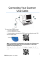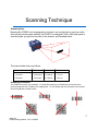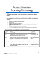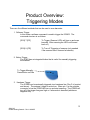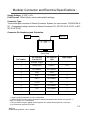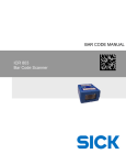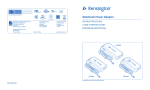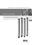
1
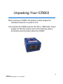
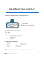
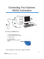
QUICK START MANUAL
ICR803
Bar Code Scanner
Getting Started
•
•
•
•
•
•
•
•
•
•
Unpacking your ICR803
Identifying your ICR803
– Configuration Sheet
Quick Start
– Connecting Your Scanner
– Scanning Technique
• Scan View
• Scan Orientation
Product Overview
– Scanning Technology
– Triggering Modes
Depth Of Field & Field Of View Charts
Mechanical Dimensions
Modular Connector & Electrical Specifications
Agency Compliance Information
RoHS / WEEE Information
Technical Assistance
3
4
5
8
11
13
14
15
16
17
2
SICK AG
ICR803 Getting Started – Rev A 04/2007
Unpacking Your ICR803
When receiving a ICR803, the product is either shipped as
individual scanners or as part of a kit.
A kit includes the ICR803 scanner, RS-232 or USB Cable, Power
Supply (for RS-232 version) and a CD containing various
documents and information about the ICR803.
3
SICK AG
ICR803 Getting Started – Rev A 04/2007
Identifying Your Scanner
On the bottom of your scanner you will see a yellow label as shown below:
Part Number
SICK
PN: ICR803-XYZAB
REV: A
SN: YYMMDD-NNN
Revision Level (A in this example)
The configurations for the ICR803 are as follows:
ICR803-XYZAB
Where:
X=
A for Smart Focus (SF) Reader (see appendix A for details)
B for Standard Range (SR) Reader (see appendix A for details)
Y =
Z =
A =
0 for front reading window
2 for RJ45 interface connector
0 for True RS232 output
7 for USB output
1 for 5 Volt Unit
B=
Sick part number cross reference:
SICK P/N
6034210
6034211
6034212
6034213
Device name
ICR803-A0201
ICR803-B0201
ICR803-A0271
ICR803-B0271
NOTE:
If you see a different part number then you may have a custom scanner. Please consult with SICK AG to determine product configuration.
4
SICK AG
ICR803 Getting Started – Rev A 04/2007
Connecting Your Scanner:
RS232 Connection
1
4
3
2
To connect your ICR803 scanner:
1. Connect RS-232 Cable to PC
2. Connect RS-232 Cable to ICR803
3. Connect Power
To Trigger Manually :
Press the button on the side of the
ICR803
Note: See page 9 for other ways to trigger the ICR803
5
SICK AG
ICR803 Getting Started – Rev A 04/2007
Connecting Your Scanner:
USB Cable
2
1
4
3
To connect your ICR803 scanner:
1, Connect USB Cable to PC
2. Connect USB Cable to ICR803
3. Using the button on the side of the ICR803, scan the configuration code “USB
keyboard wedge” below:
Note: For configuration and image acquisition via software, the USB signal has to
be emulated into a serial signal (USB Com Port Emulation). For this you can
download an USB emulation driver on
http://www.sick.com/home/factory/downloads/downloads_auto_ident/en.html
for free. Scan the bar code below to set the ICR803 into USB Com Port Emulation
mode:
6
SICK AG
ICR803 Getting Started – Rev A 04/2007
Scanning Technique
Scanning Area
Because the ICR803 is an imaging device it doesn’t use a single line to scan bar codes.
As such the scanning area used by the ICR803 is rectangular ( 640 x 480) and grows in
size the farther you get from the face of the scanner, as illustrated below:
The scan window size is as follows:
Position From Front
5.0 inches
7.0 inches
Vertical
2.42 inches
3.40 inches
Horizontal
3.8 inches
5.3 inches
Tolerance
.1 inch
.17 inch
9.0 inches
4.31inches
6.7 inches
.23 inch
Scanning Orientation
The ICR803 can read in any orientation. To assist with scanning, the ICR803 has a scan line (red or
green) that appears in the middle of the imaging area. To scan simply align the aiming line in the general
area of the barcode as shown below.
7
SICK AG
ICR803 Getting Started – Rev A 04/2007
Product Overview:
Scanning Technology
The ICR803 is an area imager, the latest in bar code scanning technology. (Note: area
Imagers are also known as: 2D bar code scanners, 2D imagers, or 2D camera
readers).
As compared to conventional bar code scanners that draw a single line across a bar
code, area imagers take a picture of the bar code when triggered. This technique
allows for:
–
–
–
–
–
–
–
Reading in any orientation (360 degree reading)
No moving parts
Reading of newer bar code symbologies
Reading of multiple barcodes at once
Reading of a specific barcode in an area (e.g. only read the barcode in the left half of the
image)
Taking pictures (Application Example: Proof of Delivery)
Vision Processing (Application Example: Detection the absence or presence of an object)
See the chart below for a comparison of scanning technologies:
Scanner
Type
Scanner
Technology
Scanning
Technique
Wand
No Moving Parts, Contact Only, Linear Bar Codes Only
Swipe Across Bar Code
CCD
No Moving Parts, Contact to Near Contact, Linear and
Stacked Linear bar codes (depending on model)
Touch scanner to Code
Laser
Moving Mirror, Near Contact to Far Distance (depending
on model), Linear and Stacked Linear (e.g. PDF417) bar
codes
Point and Shoot (must be
aligned)
Linear Imager
No Moving Parts, Near Contact to Away (depending on model), Point and Shoot (linear)
Linear Bar Codes and Stacked Linear
Swipe Up/Down (stacked)
2D Imager
No Moving Parts, Near Contact to 12” (depending on model),
Linear, Stacked Linear, 2D (Matrix) bar codes, OCR, and
picture taking capability
Point and Shoot, True
Omnidirectional scanning
8
SICK AG
ICR803 Getting Started – Rev A 04/2007
Product Overview:
Triggering Modes
There are five different methods that can be used to scan barcodes:
1. Software Trigger
In this mode a software command is used to trigger the ICR803. The
command structure is as follows:
[SYN] T [CR]
To Trigger (Scanner LED’s will turn on and scan
barcode. After scanning the LED’s will turned
back off.)
[SYN] U [CR]
To Turn off Triggering of scanner (only needed
if the scanner hasn’t scanned a barcode).
2. Button Trigger
The IC803 has an integrated button that is useful for manually triggering
the scanner.
To Trigger Manually:
Press Button on Side
3. Hardware Trigger
The ICR803 can be externally triggered via a hardware line (Rev C of product
and above). The external trigger is active low. When pin 1 on the modular
connector is low the ICR803 will turn on and start scanning. The ICR803 will
turn off if the trigger line goes high or if a barcode is decoded (whichever
happens first).
9
SICK AG
ICR803 Getting Started – Rev A 04/2007
Product Overview:
Triggering Modes
4. Scanstand Mode
When set to scanstand mode, the ICR803 will look for the label below. When an
object blocks view of the label the scanner will trigger and read the barcode on the
object.
To create this barcode print a FNC3 character using Code 128.
5. Presentation Mode
Presentation mode is similar to Scanstand Mode (above) except the ICR803 does
not require a scanstand symbol. The ICR803 will trigger and start scanning upon
any changes in the image. This includes changes in ambient light or non-bar
coded objects being placed in front of the scanner (e.g. a hand).
Note: LED power must be turned down for this mode.
10
SICK AG
ICR803 Getting Started – Rev A 04/2007
Depth Of Field:
ICR803-B Depth of Field:
ICR803-A Depth of Field:
11
SICK AG
ICR803 Getting Started – Rev A 04/2007
Depth Of Field:
ICR803 Field Of View
12
SICK AG
ICR803 Getting Started – Rev A 04/2007
Mechanical Dimensions:
All dimensions in mm
24.13
47.75
13.97
See
mounting
notes
below
44.96
21.84
39.9
12.2
22.9
Mounting Notes:
1. Two metric M3 screws used for mounting
2. Length of screw (internal length) should not be longer than 6.3mm
3. Mounting screws should not use a torque force of more than 5”/lbs.
13
SICK AG
ICR803 Getting Started – Rev A 04/2007
Modular Connector and Electrical Specifications :
Supply Voltage: +5 VDC +/-5%
Peak Current: 350mA (Note; can be reduced with settings)
Connector Type:
The modular jack connector is Stewart Connector Systems Inc. part number: SS-641010S-ANF. A suggested mating connector is Stewart Connector P/N - 937-SP-36-10-10-031, or 937SP-36-10-10-037.
Connector Pin Numbering and Orientation.
Pin 1
Pin 10
Front View
Pin Function
USB
Input/Output
Pin Number
Pin Function
True RS-232
1
External Trigger
-
-
2
Shield GND
USB D+
I/O2
3
No Connect4
No Connect4
-
4
GND
GND
-
5
RxD1
No Connect
I
6
TxD1,3
No Connect
O
7
+5 VDC
VCC
-
8
RTS1,3
No Connect
O
9
CTS1
No Connect
I
10
No Connect
USB D-
I/O2
1. Signal is polarity selectable via menu configuration.
2. USB signal have 22 Ohm series termination resistors and speed select resistor on board I/O – I =
Input, O = Output, I/O = bi-directional.
3. Pull up resistors may be applied to these signals. The resistor values should be >10k ohms.
4. No Connection required for ICR803
SICK AG
ICR803 Getting Started – Rev A 04/2007
14
Statement of Agency Compliance
Statement of Agency Compliance
This device complies with part 15 of the FCC Rules. Operation is subject to the following two conditions:
(1) this device may not cause harmful interference, and (2) this device must accept any interference
received, including interference that may cause undesired operation.
FCC Class A Compliance Statement
This equipment has been tested and found to comply with the limits for a Class A digital device pursuant
to part 15 of the FCC Rules. These limits are designed to provide reasonable protection against harmful
interference when the equipment is operated in a commercial environment. This equipment generates,
uses, and can radiate radio frequency energy and, if not installed and used in accordance with the
instructions, may cause harmful interference to radio communications.
Operation of this equipment in a residential area may cause harmful interference in which case the user
will be required to correct the interference at their own expense.
ITE class A device:
Warning
This is a class A product. In a domestic environment this product may cause radio
interference in which case the user may be required to take adequate measures.
Caution: Any changes or modifications made to this device that are not expressly approved by SICK AG Inc.
may void the user’s authority to operate the equipment.
Note: To maintain compliance with FCC Rules and Regulations, cables connected to this device must be
shielded cables, in which the cable shield wire(s) have been grounded (tied) to the connector shell.
CE Compliance Statement
The CE mark on the product indicates that the system has been tested to and conforms
with the following requirements: EN55022:1998/A1:2000/A2:2003 Class A ITE
emissions requirements, EN 55024: 1998/A1:2001/A2:2003 ITE – immunity
characteristics, and the Low Voltage Directive standard: EN 60950-1:2001 Information
Technology Equipment – Safety- Part 1: General Requirements.
LED Safety Statement
This device has been tested in accordance with EN60825-1 LED safety, and has been verified to be under
the limits of a Class 1 LED device.
For further information please contact SICK AG. See Technical Support contact on page 19.
SICK shall not be liable for use of our product with equipment (i.e., power supplies, personal computers,
etc.) that is not CE marked and does not comply with the Low Voltage Directive.
15
SICK AG
ICR803 Getting Started – Rev A 04/2007
RoHS & WEEE Compliance
Waste Electrical and Electronic Equipment Information:
This product has required the extraction and use of natural
resources for its production. It may contain hazardous substances
that could impact health and the environment, if not properly
disposed. In order to avoid the dissemination of those
substances in our environment and to diminish the pressure on
the natural resources, we encourage you to use the appropriate
take-back systems for product disposal. Those systems will reuse
or recycle most of the materials of the product you are disposing
in a sound way.
The crossed out wheeled bin symbol informs you that
the product should not be disposed of along with
municipal waste and invites you to use the appropriate
separate take-back systems for product disposal. If you need
more information on the collection, reuse, and recycling systems,
please contact your local or regional waste administration.
RoHS
The ICR803 Series is in compliance with Directive 2002/95/EC,
Restriction of the Use of Certain Hazardous Substances in
Electrical and Electronic Equipment (RoHS), dated January,
2003.
16
SICK AG
ICR803 Getting Started – Rev A 04/2007
8012078/2007-04 ∙ HaWa <PM6.5/Word/PDF>/VD ∙ Printed in Germany ∙ Subject to change without notice ∙ The specified product features and technical data do not represent any guarantee ∙ 05 Pre int61
Australia
Phone+61 3 9497 4100
1800 33 48 02 – tollfree
E-Mail [email protected]
Belgium/Luxembourg
Phone +32 (0)2 466 55 66
E-Mail [email protected]
Brasil
Phone+55 11 3215-4900
E-Mail [email protected]
Ceská Republika
Phone+420 2 57 91 18 50
E-Mail [email protected]
China
Phone+852-2763 6966
E-Mail [email protected]
Danmark
Phone+45 45 82 64 00
E-Mail [email protected]
Deutschland
Phone+49 211 5301-270
E-Mail [email protected]
España
Phone+34 93 480 31 00
E-Mail [email protected]
France
Phone+33 1 64 62 35 00
E-Mail [email protected]
Great Britain
Phone+44 (0)1727 831121
E-Mail [email protected]
India
Phone+91–22–4033 8333
E-Mail [email protected]
Israel
Phone+972-4-999-0590
E-Mail [email protected]
Italia
Phone+39 02 27 43 41
E-Mail [email protected]
Österreich
Phone+43 (0)22 36 62 28 8-0
E-Mail [email protected]
Polska
Phone+48 22 837 40 50
E-Mail [email protected]
Republic of Korea
Phone+82-2 786 6321/4
E-Mail [email protected]
Republika Slowenija
Phone+386 (0)1-47 69 990
E-Mail [email protected]
România
Phone+40 356 171 120
E-Mail [email protected]
Russia
Phone+7 495 775 05 34
E-Mail [email protected]
Schweiz
Phone+41 41 619 29 39
E-Mail [email protected]
Singapore
Phone+65 6744 3732
E-Mail [email protected]
Suomi
Phone+358-9-25 15 800
E-Mail [email protected]
Sverige
Phone+46 10 110 10 00
E-Mail [email protected]
Taiwan
Phone+886 2 2365-6292
E-Mail [email protected]
Türkiye
Phone+90 216 587 74 00
E-Mail [email protected]
USA/Canada/México
Phone+1(952) 941-6780
1 800-325-7425 – tollfree
E-Mail [email protected]
Japan
Phone+81 (0)3 3358 1341
E-Mail [email protected]
Nederlands
Phone+31 (0)30 229 25 44
E-Mail [email protected]
Norge Phone+47 67 81 50 00
E-Mail [email protected]
SICK AG | Waldkirch | Germany | www.sick.com
More representatives and agencies
in all major industrial nations at
www.sick.com